Embed Size (px)
Citation preview
1
Cellular Networks Guest lecture by Li Erran Li, Bell Labs
COS 461: Computer Networks 4/18/2012 W 10-‐10:50am in Architecture N101
1!
Cellular Core Network!Cellular Networks Impact our Lives
More Mobile Connection!
More Mobile Information
Sharing!
More Mobile Users!
2!
1010100100001011001!0101010101001010100!1010101010101011010!1010010101010101010!0101010101001010101!
More Infrastructure!Deployment!
Mobile Data Tsunami Challenges Current Cellular Technologies
• Global growth 18 Omes from 2011 to 2016
• AT&T network: – Over the past five years,
wireless data traffic has grown 20,000%
– At least doubling every year since 2007
• ExisOng cellular technologies are inadequate – Fundamental redesign of
cellular networks is needed
Source: CISCO Visual Networking Index (VNI) Global Mobil Data Traffic Forecast 2011 to 2016!
3!
Outline
Goal of this lecture: understand the basics of current networks
• Basic Architecture of LTE • Access Procedure
– Why no carrier sensing • ConnecOon Setup
– Unlike WiFi, need to keep the same IP address at different a]achment points
• Mobility Management • Power Management and Mobile Apps • Differences between 3G and LTE • Conclusion
4!
Cellular Core Network!
eNodeB 3! S-GW 2!P-GW!
5!
S-GW 1!
eNodeB 1 !
eNodeB 2!
Internet and!Other IP Networks!
GTP Tunnels!UE 2!
UE 1!
LTE Infrastructure
MME/PCRF/HSS!
• UE: user equipment • eNodeB: base sta5on • S-‐GW: serving
gateway • P-‐GW: packet data
network gateway • MME: mobility
management en5ty • HSS: home subscriber
server • PCRF: policy charging
and rule func5on
6!
LTE Architecture (Cont’d)
• eNodeB, S-‐GW and P-‐GW are involved in session setup, handoff, rou5ng
User Equipment (UE) Gateway
(S-GW)
Mobility Management
Entity (MME)
Network Gateway (P-GW)
Home Subscriber
Server (HSS)
Policy Control and Charging Rules
Func5on (PCRF)
Station (eNodeB)
Base Serving Packet Data
Control Plane!Data Plane!
2
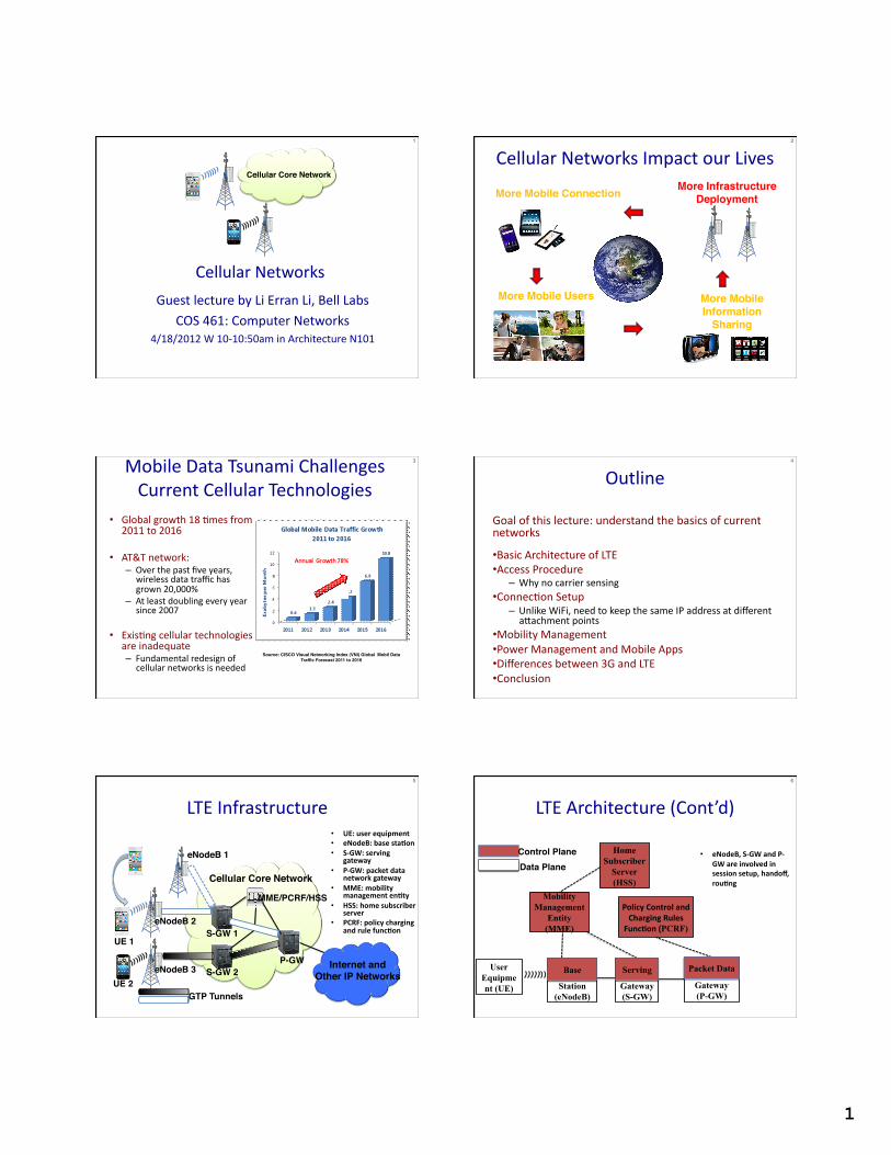
Access Procedure
• Cell Search – Base staOon broadcasts synchronizaOon signals and cell system informaOon (similar to WiFi)
– UE obtains physical layer informaOon
• UE acquires frequency and synchronizes to a cell
• Determine the start of the downlink frame
• Determine the cell idenOty
• Random access to establish a radio link
7!
Base station
UE 2!UE 1!
Client Base station Core network
Step 1: random access request (pick one of 64 preambles)
Step 2: random access response
Step 3: transmission of mobile ID
Step 4: contention resolution msg Only if UE is not known in Base station
Random Access
Adjust uplink timing
If ID in msg matches UE ID, succeed. If collision, ID will not match!
8!
Base station
Random Access (Cont’d)
UE 2!UE 1!
Why not carrier sensing like WiFi? • Base sta5on coverage is much larger than WiFi AP
– UEs most likely cannot hear each other
• How come base sta5on can hear UEs’ transmissions?
– Base sta5on receivers are much more sensi5ve and expensive
9!
ConnecOon Setup
• Session Requests – UE to base staOon – Base staOon to MME
• MME obtains subscriber info from HSS, selects S-‐GW and P-‐GW
– S-‐GW sends to P-‐GW • P-‐GW obtains policy from PCRF
10!
S-GW!UE! P-GW!
Session Request
MME!
ConnecOon Setup (Cont’d)
• Session Response – Establishes GPRS Tunnels (GTP) between S-‐GW and P-‐GW, between S-‐GW and UE
– Base staOon allocates radio resources to UE
11!
S-GW!UE! P-GW!
MME!
Session Response
Mobility Management
Handoff • Handoff without change of S-‐GW – No change at P-‐GW
• Handoff with change of S-‐GW or MME
• Inter-‐technology handoff (LTE to 3G)
12!
S-GW!UE! P-GW!
MME!
3
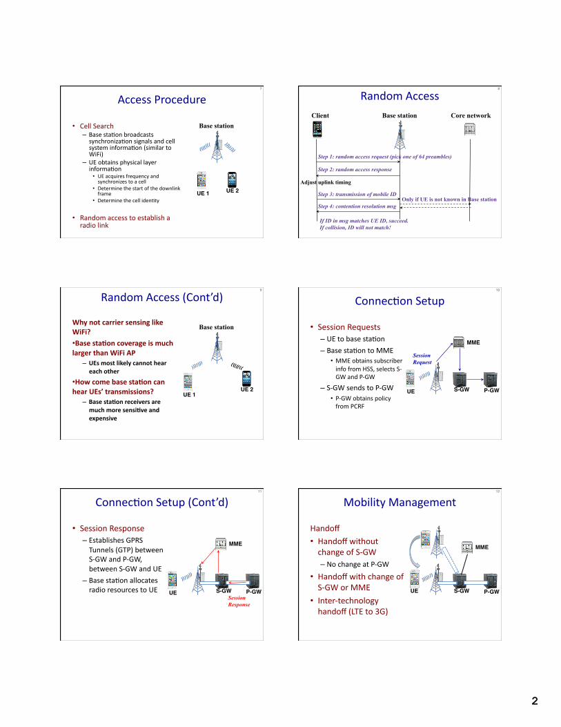
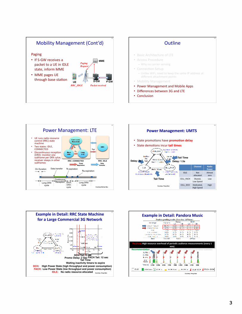
Mobility Management (Cont’d)
Paging • If S-‐GW receives a packet to a UE in IDLE state, inform MME
• MME pages UE through base staOon
13!
S-GW!UE! P-GW!
MME!
RRC_IDLE Packet received
Paging Request
Outline
• Basic Architecture of LTE • Access Procedure
– Why no carrier sensing
• ConnecOon Setup – Unlike WiFi, need to keep the same IP address at different a]achment points
• Mobility Management • Power Management and Mobile Apps • Differences between 3G and LTE • Conclusion
14!
Power Management: LTE • UE runs radio resource
control (RRC) state machine
• Two states: IDLE, CONNECTED
• DisconOnuous recepOon (DRX): monitor one subframe per DRX cylce; receiver sleeps in other subframes
15!
!"#$%&'()&*+*,-
.#/%0/1#12&(-*-3%0#/
4/&'1$5%0#/
6#/7&'()&*+*,-
'5%5&%$5/28-$ !"&-930$5%0#/!"#&-930$5%0#/
6#/7&'()&*+*,-
!"#$%#&"&'()*+*,$%"#
-."/$(0)1
))!2!3445!650 ))!27085
8"#9(0)1
0)1
6%:*/(*;,%/<$%"#
0<$<($/<#'=*/
6$<%>6%'
6%
Courtesy:Morley Mao!
Power Management: UMTS�
• State promoOons have promo5on delay
• State demoOons incur tail 5mes
Tail Time!
Tail Time!
Delay: 1.5s!Delay: 2s!
Channel � Radio Power �
IDLE � Not allocated �
Almost zero �
CELL_FACH � Shared, Low Speed �
Low�
CELL_DCH � Dedicated, High Speed �
High �Courtesy: Feng Qian!
16!
Example in Detail: RRC State Machine for a Large Commercial 3G Network
Promo Delay: 2 Sec DCH Tail: 5 sec
FACH Tail: 12 sec
DCH: !High Power State (high throughput and power consumption)!FACH: !Low Power State (low throughput and power consumption)!
IDLE: !No radio resource allocated!
Tail Time!Waiting inactivity timers to expire
Courtesy: Feng Qian!
17!
Example in Detail: Pandora Music
Problem: High resource overhead of periodic audience measurements (every 1 min)
Recommenda5on: Delay transfers and batch them with delay-‐sensi5ve transfers
Courtesy: Feng Qian!
18!
4
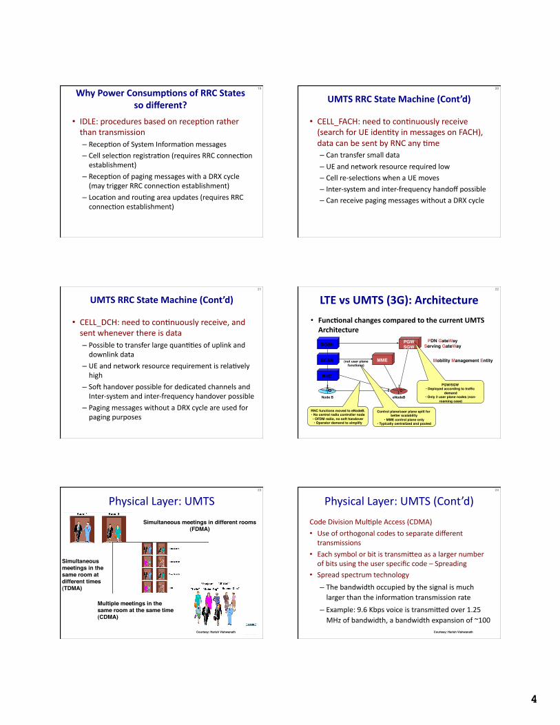
• IDLE: procedures based on recepOon rather than transmission – RecepOon of System InformaOon messages – Cell selecOon registraOon (requires RRC connecOon establishment)
– RecepOon of paging messages with a DRX cycle (may trigger RRC connecOon establishment)
– LocaOon and rouOng area updates (requires RRC connecOon establishment)
19!
Why Power Consump5ons of RRC States so different? �
• CELL_FACH: need to conOnuously receive (search for UE idenOty in messages on FACH), data can be sent by RNC any Ome – Can transfer small data
– UE and network resource required low – Cell re-‐selecOons when a UE moves – Inter-‐system and inter-‐frequency handoff possible – Can receive paging messages without a DRX cycle
20!
UMTS RRC State Machine (Cont’d)�
• CELL_DCH: need to conOnuously receive, and sent whenever there is data – Possible to transfer large quanOOes of uplink and downlink data
– UE and network resource requirement is relaOvely high
– Soh handover possible for dedicated channels and Inter-‐system and inter-‐frequency handover possible
– Paging messages without a DRX cycle are used for paging purposes
21!
UMTS RRC State Machine (Cont’d)�
GGSN!
SGSN!
RNC!
Node B! eNodeB!
RNC functions moved to eNodeB.!• No central radio controller node!• OFDM radio, no soft handover!• Operator demand to simplify!
Mobility Management Entity!MME!(not user plane !functions)!
Control plane/user plane split for better scalability!
• MME control plane only!• Typically centralized and pooled!
PGWSGW!
PDN GateWay !Serving GateWay !
PGW/SGW !• Deployed according to traffic
demand!• Only 2 user plane nodes (non-
roaming case)!
• Func5onal changes compared to the current UMTS Architecture
LTE vs UMTS (3G): Architecture 22!
Physical Layer: UMTS
Simultaneous meetings in different rooms (FDMA)!
Simultaneous meetings in the same room at different times (TDMA) !
Multiple meetings in the same room at the same time (CDMA)!
23!
Courtesy: Harish Vishwanath!
Code Division MulOple Access (CDMA)
• Use of orthogonal codes to separate different transmissions
• Each symbol or bit is transmi]ed as a larger number of bits using the user specific code – Spreading
• Spread spectrum technology
– The bandwidth occupied by the signal is much larger than the informaOon transmission rate
– Example: 9.6 Kbps voice is transmi]ed over 1.25 MHz of bandwidth, a bandwidth expansion of ~100
24!
Courtesy: Harish Vishwanath!
Physical Layer: UMTS (Cont’d)
5
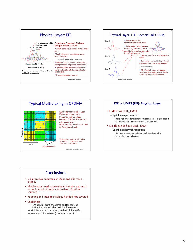
Orthogonal Frequency Division Multiple Access (OFDM) Closely spaced sub-carriers without guard band"
Each sub-carrier undergoes (narrow band) flat fading"
- Simplified receiver processing" Frequency or multi-user diversity through coding or scheduling across sub-carriers" Dynamic power allocation across sub-carriers allows for interference mitigation across cells"
Orthogonal multiple access"
Frequency
Narrow Band (~10 Khz)
Wide Band (~ Mhz)
T large compared to channel delay spread
Sub-carriers remain orthogonal under multipath propagation
T 1
25!
Courtesy: Harish Vishwanath!
Physical Layer: LTE Physical Layer: LTE (Reverse link OFDM)
User 1
User 2
User 3
Efficient use of spectrum by multiple users
Sub-carriers transmitted by different users are orthogonal at the receiver
- No intra-cell interference
CDMA uplink is non-orthogonal since synchronization requirement is ~ 1/W and so difficult to achieve
Users are carrier synchronized to the base
Differential delay between users’ signals at the base need to be small compared to symbol duration
W
26!
Courtesy: Harish Vishwanath!
Typical MulOplexing in OFDMA
Each color represents a user" Each user is assigned a
frequency-time tile which consists of pilot sub-carriers and data sub-carriers"
Block hopping of each user’s tile for frequency diversity"
Time
Freq
uenc
y
Typical pilot ratio: 4.8 % (1/21) for LTE for 1 Tx antenna and 9.5% for 2 Tx antennas
27!
Courtesy: Harish Vishwanath!
Pilot sub-carriers"
• UMTS has CELL_FACH – Uplink un-‐synchronized
• Base staOon separates random access transmissions and scheduled transmissions using CDMA codes
• LTE does not have CELL_FACH – Uplink needs synchronizaOon
• Random access transmissions will interfere with scheduled transmissions
28!
LTE vs UMTS (3G): Physical Layer �
Conclusions • LTE promises hundreds of Mbps and 10s msec latency
• Mobile apps need to be cellular friendly, e.g. avoid periodic small packets, use push noOficaOon services
• Roaming and inter-‐technology handoff not covered
• Challenges – P-‐GW central point of control, bad for content distribuOon, and scalable policy enforcement
– Mobile video will be more than half of the traffic – Needs lots of spectrum (spectrum crunch)
29!