Embed Size (px)
Citation preview

8/3/2019 Ccip Lessons
http://slidepdf.com/reader/full/ccip-lessons 1/34
Implementation of digital control system
C(kT) = ∑m i=0 a(i)r[(k-i)T] + ∑ n j=1 b(j)c[(k-j)T]
The above equation represents a control law in difference equation form. Performance is directly related to
representations of coefficients a(i), b(j); processes involved in arithmetic operations; data input (r ) and output (c
), i/o for multiple control tasks for computer.
Control logic: symbolic logical design and Boolean algebra
Computer architecture for control: control algorithm input, output, calculation, control, information
storage. Speed, power etc. are considered – microcontrollers are specialized.
Software for control: apart from solving difference equations, human command interfacing through control
panels and switching discrete event control like alarms and timers, device calibration, environmental protection,
checks/audits required. System integration in time and space, scheduling are tough. Developing algorithms and
implementing on languages – critical task.
Software engineering in control: defining SDLC:- requirement specs-design-development-integrate-test-
maintain. Use of DFD etc. to depict the system.
Real time design for digital control: calculating time for each digitization step is important. Interrupt latency,
context switching are to be worked out.
Software for direct design method: use of structural programming, numerical techniques
Real time scheduling: complex industrial process, aircraft control etc. require system integration that involves
scheduling various jobs.
Operating system: managing resources of computer system, schedule periodic tasks, coordinate
communication between tasks, integrity of control system etc.
Sampling time selection: response to given control input, external disturbance, sensitivity to plant model etc.
are tuned to desired ones- optimal sampling, multi-rate sampling (more complex)

8/3/2019 Ccip Lessons
http://slidepdf.com/reader/full/ccip-lessons 2/34
Introduction to modern control theory
Conventional classical control theory is based on frequency domain. It is only applicable to single-input-single-
output (SISO) systems that are linear time-invariant (LTI).
Modern control theory is applicable to time-varying as well as non-linear multi-input multi-output (MIMO)
systems.
State variable: Smallest set of variables whose knowledge at t=t 0 together with subsequent inputs at t≥t0
completely determines the behaviour of the system for any time t≥ t0
Meaning of linear time invariant system:
Superposition theorem:
r1 (t) c1 (t) and r2 (t) c2 (t)
a1 r1 (t) + a2 r2 (t) a1 c1 (t) + a2 c2 (t)
c(t) = f{r(t)} is the time domain transfer function.
c(kT) = f{ a1 r1 (kT) + a2 r2 (kT)} = a1 f{ r 1 (kT)} + a2 f{r2 (kT)}
Ex. c(t) = r(t)+α. Then, c1= r1+α and c2= r2+α
For r = a1 r1 + a2 r2
c(actual) = a1 r1 + a2 r2 + a1α + a2α.
c(reqd for SPT) = a1 r1 + a2 r2 + α
Hence, the function is non-linear.
c(kT)=r^2(kT) is non-linear.
c(t) = dr(t)/dt i.e. c(kT) = (1/T)(r(kT)-r(kT-T))
Time invariance:
When c(t-τ)=f{r(t-τ)} or c((k-p)T) = f{r((k-p)T)}
System TF followed by time delay Ξ Time delay followed by system TF
Ex. c (t) + c(t) = t r(t)

8/3/2019 Ccip Lessons
http://slidepdf.com/reader/full/ccip-lessons 3/34
Here, c (t-τ) + c(t-τ) = (t-τ) r(t-τ) taking first the system TF, then the delay.
Again, c (t-τ) + c(t-τ) = t r(t-τ) taking first the delay, then the system TF.
∴ This is not time invariant.
Ex. c(kT) = kT r(kT)
Ex. c((k+1)T)-c(kT) = r(kT)
Let x1 , x2, x3 , … , xn be the state variables of a system and the state vector is denoted as X(t) in continuous time
domain at time t. Also, u(t) is the input variable at time t.
Then the system can be described in terms of differential equations involving the rate of change of state
variables with respect to time.
ẋ =Ax(t) + Bu(t)
ẍ ẏ ϊ ϊ ύ ϋ
L + Ri + vί c = v and Cύc = i describes the differential equations governing a L-R-C circuit.
Here, = di/dt andί ύc = d vc /dt are the rate of change of current and voltage across the capacitance respectively.
Taking x1 = i(t) and x2 = vc(t) with u(t)=applied voltage v; one can write ẋ=Ax(t) + Bu(t)
One can easily obtain A=[-R/L, -1/L; 1/C, 0] and B=[1/L; 0].
Electric Motor Transfer Function:
Simple harmonic motion
Spring-mass system
Free falling body
State-Space methods in continuous domain
Consider n-th order differential equation describing a system:
y(n) + a1 y(n-1) + …+ an-1ẏ + any = u
8/3/2019 Ccip Lessons
http://slidepdf.com/reader/full/ccip-lessons 4/34
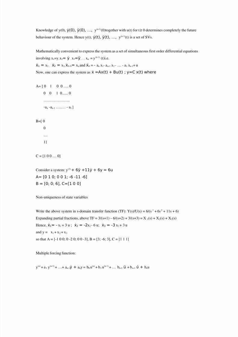
Knowledge of y(0), ẏ(0), ÿ(0), …, y(n-1)(0)together with u(t) for t≥ 0 determines completely the future
behaviour of the system. Hence y(t), ẏ(t), ÿ(t), …, y(n-1)(t) is a set of SVs.
Mathematically convenient to express the system as a set of simultaneous first order differential equations
involving x1=y, x2= ẏ , x3=ÿ, … , xn = y(n-1)
(t)i.e.
ẋ1 = x2 ; ẋ2 = x3; ẋn-1= xn and ẋn = - an x1- an-1 x2 - … - a1 xn-1+ u
Now, one can express the system as ẋ =Ax(t) + Bu(t) ; y=C x(t) where
A= [ 0 1 0 0 …. 0
0 0 1 0...... 0
………………...
-an -an-1 …..… - a1 ]
B=[ 0
0
…
1]
C = [1 0 0 … 0]
Consider a system: y(3) + 6ÿ +11ẏ + 6y = 6u
A= [0 1 0; 0 0 1; -6 -11 -6]B = [0; 0; 6], C=[1 0 0]
Non-uniqueness of state variables
Write the above system in s-domain transfer function (TF): Y(s)/U(s) = 6/(s3 + 6s2 + 11s + 6)
Expanding partial fractions, above TF = 3/(s+1) – 6/(s+2) + 3/(s+3) = X 1(s) + X2(s) + X3(s)
Hence, ẋ1= - x1 + 3 u ; ẋ2 = -2x2 - 6 u; ẋ3 = -3 x3 + 3 u
and y = x1 + x2 + x3
so that A = [-1 0 0; 0 -2 0; 0 0 -3], B = [3; -6; 3], C = [1 1 1]
Multiple forcing function:
y(n) + a1 y(n-1) + …+ an-1ẏ + any = b0 u(n) + b1 u(n-1) + … bn-2 ü + bn-1 ύ + bnu

8/3/2019 Ccip Lessons
http://slidepdf.com/reader/full/ccip-lessons 5/34
Now, for unique solution, derivatives of u must be eliminated from state equations. Define:
x1=y- β0u ; x2= ẏ- β0ύ - β1u = ẋ1- β1u ; x3= ÿ - β0ü - β1ύ - β2 u = ẋ2 - β2 u ; … , xn = ẋn-1 - βn-1 u
Solving, we get β0 = b0; β1 = b1- a1 β0 ; β2 = b2- a1 β1- a2 β0;
βn = bn- a1 βn-1- … - an-1 β1 - an β0
Hence, A = same as earlier; C = same as earlier
B = [β1 ; β2 ; … ; βn-1 ; βn ] ; D = β0 = b0
Derivatives only affect the B matrix. The Transfer function has introduced zeroes.
Y(s)/U(s) = ( b0 sn + b1 sn-1 + … + bn-1 s + bn )/( sn + a1 sn-1 + … + an-1 s + an )
Ex. y(3) + 18 ÿ + 192 ẏ + 640y = 160 ύ + 640 u
Y(s)/U(s) = {4(s+4)/(s+16)}*{40/s(s+2)}
A= [0 1 0; 0 0 1;-640 -192 -18]; B = [0; 160; -2240]; C=[1 0 0]; D=[640]
Solution of the homogeneous state equation:
ẋ = Ax solves to x = exp (At) x(0) = x(0){ I + At + …. + (1/k!)A k tk + … } converges for all t.
exp(-At) is inverse of exp(At). Derivative of exp(At) = A exp(At)
Laplace transform approach:
X(s) = (sI-A) -1 x(0)
Then, x(t) = L-1 {(sI-A) -1 }
(sI-A) -1 = I/s + A/s2 + A2 /s3 + ….
L-1 {(sI-A) -1 }= I + At + (1/2!)A2t2 + (1/3!)A3 t3 + …. = exp(At)
State transition matrix Φ(t) Phi(t):
x(t) = Φ(t)x(0)i.e. Φ(t) = exp(At)
Φ(t1 + t2)= exp(A(t1+ t2))= exp(A(t1)) exp(A(t2))= Φ(t1 ) Φ(t2)
Φ(t)contains the Eigenvalues exp(λit) for non-repetitive roots.
Φ(t)contains texp(λ jt), …, tm exp(λ jt) for m-times repeating roots.
Also, (Φ(t) ) n= Φ(nt) and Φ(t2 - t1) Φ(t1 - t0) = Φ(t2 - t0) = Φ(t1 - t0) Φ(t2 - t1)
8/3/2019 Ccip Lessons
http://slidepdf.com/reader/full/ccip-lessons 6/34
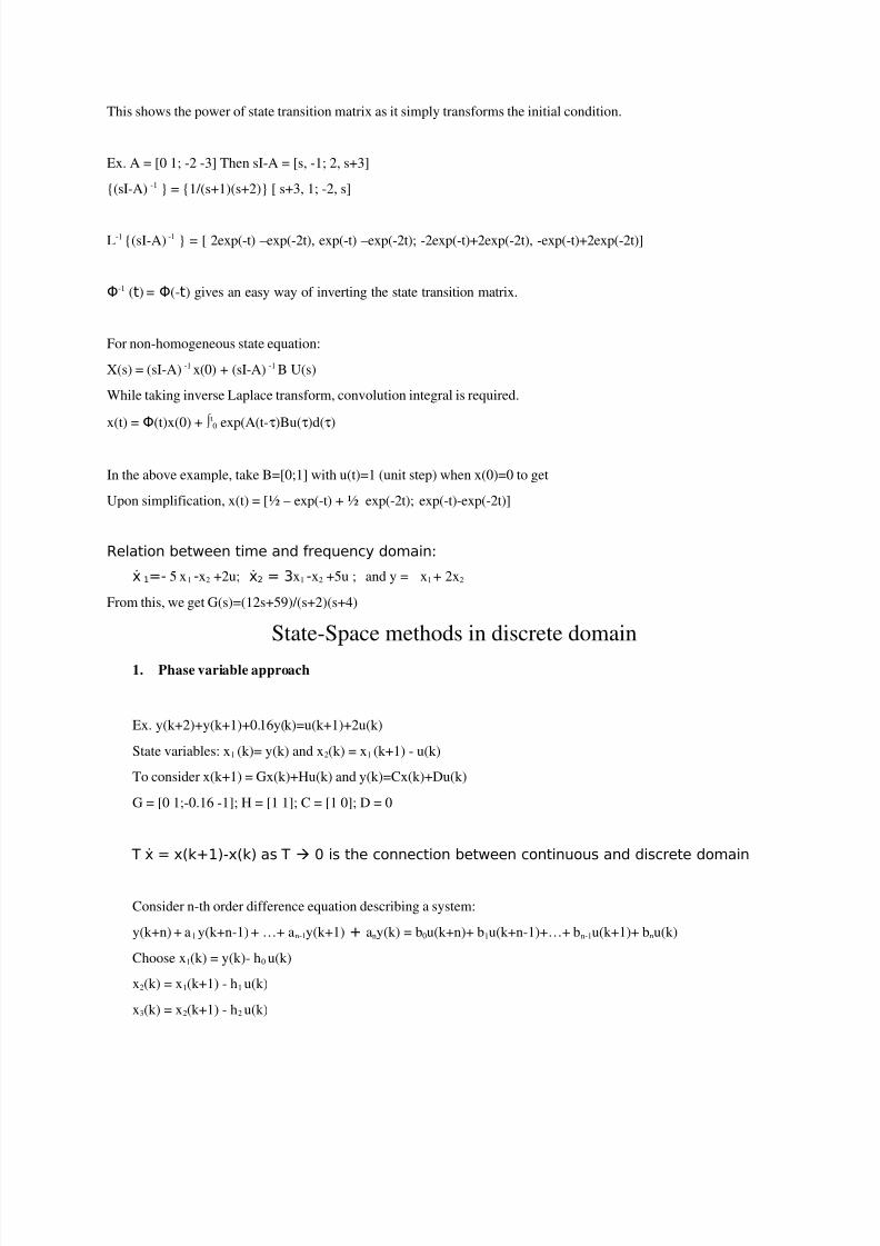
This shows the power of state transition matrix as it simply transforms the initial condition.
Ex. A = [0 1; -2 -3] Then sI-A = [s, -1; 2, s+3]
{(sI-A) -1 } = {1/(s+1)(s+2)} [ s+3, 1; -2, s]
L-1 {(sI-A) -1 } = [ 2exp(-t) –exp(-2t), exp(-t) –exp(-2t); -2exp(-t)+2exp(-2t), -exp(-t)+2exp(-2t)]
Φ-1 (t) = Φ(-t) gives an easy way of inverting the state transition matrix.
For non-homogeneous state equation:
X(s) = (sI-A) -1 x(0) + (sI-A) -1 B U(s)
While taking inverse Laplace transform, convolution integral is required.
x(t) = Φ(t)x(0) + ∫ t0 exp(A(t-τ)Bu(τ)d(τ)
In the above example, take B=[0;1] with u(t)=1 (unit step) when x(0)=0 to get
Upon simplification, x(t) = [½ – exp(-t) + ½ exp(-2t); exp(-t)-exp(-2t)]
Relation between time and frequency domain:
ẋ 1=- 5 x1 -x2 +2u; ẋ2 = 3x1 -x2 +5u ; and y = x1 + 2x2
From this, we get G(s)=(12s+59)/(s+2)(s+4)
State-Space methods in discrete domain
1. Phase variable approach
Ex. y(k+2)+y(k+1)+0.16y(k)=u(k+1)+2u(k)
State variables: x1 (k)= y(k) and x2(k) = x1 (k+1) - u(k)
To consider x(k+1) = Gx(k)+Hu(k) and y(k)=Cx(k)+Du(k)
G = [0 1;-0.16 -1]; H = [1 1]; C = [1 0]; D = 0
T ẋ = x(k+1)-x(k) as T 0 is the connection between continuous and discrete domain
Consider n-th order difference equation describing a system:
y(k+n) + a1 y(k+n-1) + …+ an-1y(k+1) + any(k) = b0u(k+n)+ b1u(k+n-1)+…+ bn-1u(k+1)+ bnu(k)
Choose x1(k) = y(k)- h0 u(k)
x2(k) = x1(k+1) - h1 u(k)
x3(k) = x2(k+1) - h2 u(k)
8/3/2019 Ccip Lessons
http://slidepdf.com/reader/full/ccip-lessons 7/34
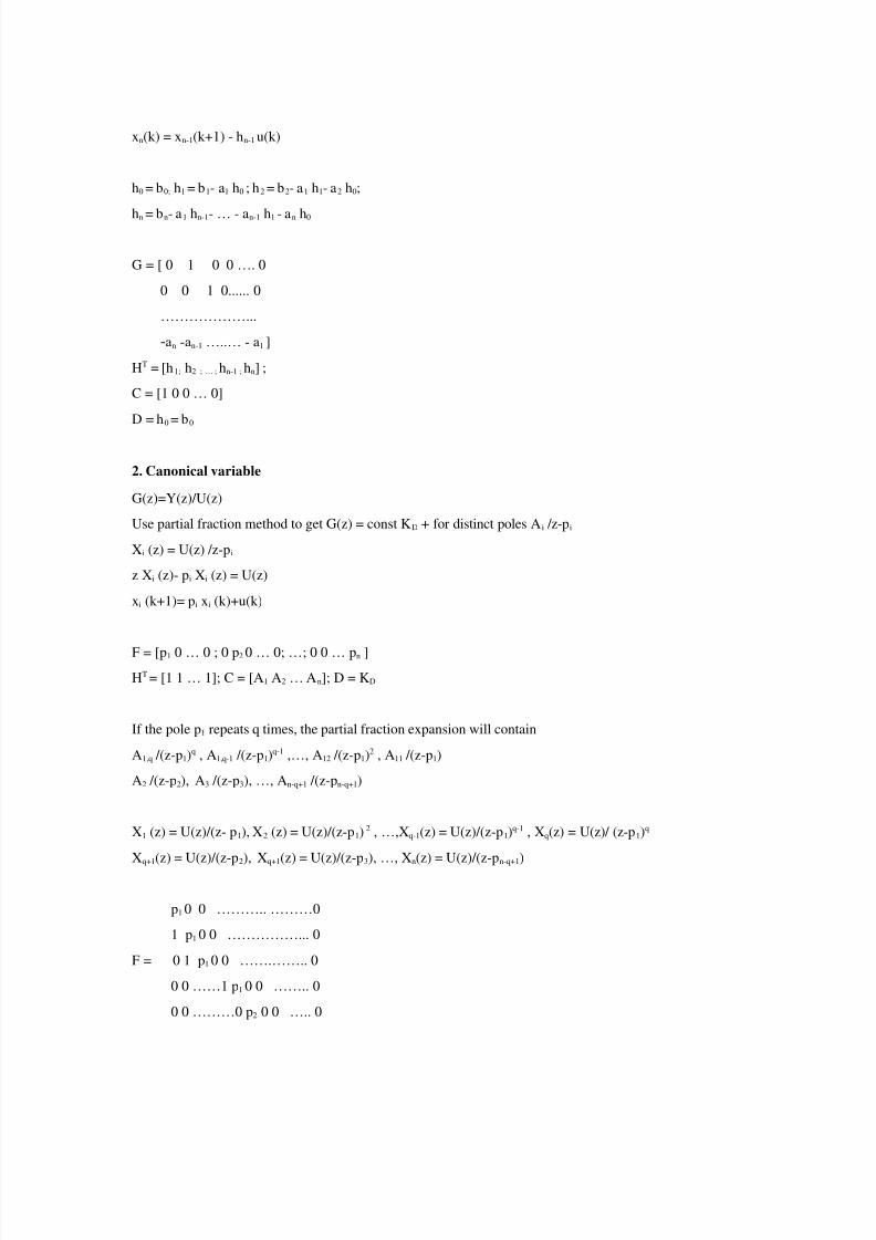
xn(k) = xn-1(k+1) - hn-1 u(k)
h0 = b0; h1 = b1- a1 h0 ; h2 = b2- a1 h1- a2 h0;
hn = bn- a1 hn-1- … - an-1 h1 - an h0
G = [ 0 1 0 0 …. 0
0 0 1 0...... 0
………………...
-an -an-1 …..… - a1 ]
HT = [h1; h2 ; … ; hn-1 ; hn] ;
C = [1 0 0 … 0]
D = h0 = b0
2. Canonical variable
G(z)=Y(z)/U(z)
Use partial fraction method to get G(z) = const KD + for distinct poles Ai /z-pi
Xi (z) = U(z) /z-pi
z Xi (z)- pi Xi (z) = U(z)
xi (k+1)= pi xi (k)+u(k)
F = [p1 0 … 0 ; 0 p2 0 … 0; …; 0 0 … pn ]
HT = [1 1 … 1]; C = [A1 A2 … An]; D = KD
If the pole p1 repeats q times, the partial fraction expansion will contain
A1,q /(z-p1)q , A1,q-1 /(z-p1)q-1 ,…, A12 /(z-p1)2 , A11 /(z-p1)
A2 /(z-p2), A3 /(z-p3), …, An-q+1 /(z-pn-q+1)
X1 (z) = U(z)/(z- p1), X2 (z) = U(z)/(z-p1) 2 , …,Xq-1(z) = U(z)/(z-p1)q-1 , Xq(z) = U(z)/ (z-p1)q
Xq+1(z) = U(z)/(z-p2), Xq+1(z) = U(z)/(z-p3), …, Xn(z) = U(z)/(z-pn-q+1)
p1 0 0 ……….. ………0
1 p1 0 0 ……………... 0
F = 0 1 p1 0 0 …….…….. 0
0 0 ……1 p1 0 0 …….. 0
0 0 ………0 p2 0 0 ….. 0
8/3/2019 Ccip Lessons
http://slidepdf.com/reader/full/ccip-lessons 8/34
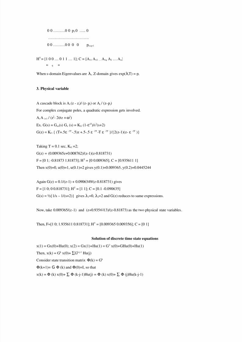
0 0 ………0 0 p3 0 ….. 0
………………………….
0 0 ………0 0 0 0 pn-q+1
HT
= [1 0 0 … 0 1 1 … 1]; C = [A11 A12 … A1q A2 … An] q
When s-domain Eigenvalues are λi, Z-domain gives exp(λiT) = pi
3. Physical variable
A cascade block is Ai (z - zi)/ (z- pi) or A j / (z- p j)
For complex conjugate poles, a quadratic expression gets involved.
AiA
i+1 / (z2- 2 z +σ
ω2)
Ex. G(s) = Gzo(s) Gx (s) = KG (1-εsT)/s2(s+2)
G(z) = KG { (T+.5ε -2T -.5)z +.5-.5 ε -2T -T ε -2T }/{2(z-1)(z- ε -2T )}
Taking T = 0.1 sec, KG =2;
G(z) = (0.009365z+0.008762)/(z-1)(z-0.818731)
F = [0 1; -0.81873 1.81873]; HT = [0 0.009365]; C = [0.935611 1]
Then x(0)=0, u(0)=1, u(0.1)=2 gives y(0.1)=0.009365, y(0.2)=0.0445244
Again G(z) = 0.1/(z-1) + 0.0906349/(z-0.818731) gives
F = [1 0; 0 0.818731]; HT = [1 1]; C = [0.1 -0.090635]
G(s) = ½{1/s – 1/(s+2)} gives λ1=0, λ2=2 and G(z) reduces to same expressions.
Now, take 0.009365/(z-1) and (z+0.9356113)/(z-0.81873) as the two physical state variables.
Then, F=[1 0; 1.935611 0.818731]; HT = [0.009365 0.009356]; C = [0 1]
Solution of discrete time state equations
x(1) = Gx(0)+Hu(0); x(2) = Gx(1)+Hu(1) = G2 x(0)+GHu(0)+Hu(1)
Then, x(k) = Gk x(0)+ ∑Gk-j-1 Hu(j)
Consider state transition matrix Φ(k) = Gk
Φ(k+1)= G Φ (k) and Φ(0)=I, so that
x(k) = Φ (k) x(0)+ ∑ Φ (k-j-1)Hu(j) = Φ (k) x(0)+ ∑ Φ (j)Hu(k-j-1)

8/3/2019 Ccip Lessons
http://slidepdf.com/reader/full/ccip-lessons 9/34
y(k) = C Φ (k) x(0) + C ∑Φ(j)Hu(k-j-1) + Du(k)
Getting to State Variable representation from Z-domain TF
G(z) = Y(z)/U(z) = {Y(z)/X(z)}{(X(z)/U(z)}
= ( zw
+ f w-1 zw-1
+ … + f 1 z + f 0 )* KD /( zn
+ dn-1 zn-1
+ … + d1 z + d0 )
KDU(z) = zn X(z) + dn-1 zn-1 X(z) + … + d1 z X(z) + d0 X(z)
Y(z) = f 0 X(z)+ f 1 z X(z) + … + f w-1 zw-1 X(z) + zw X(z)
Since Z-1 {zn E(z)} = e[(k+n)T]; taking Z-1 { } of the above expressions,
We get x(k+n) + dn-1 x(k+n-1) + … + d1 x(k+1) + d0 x(k) = KD u(k)
And y(k) = f 0 x(k)+ f 1 x(k+1) + … + f w-1 x(k+w-1) + x(k+w)
Phase variables:
x1 (k) = x(k); x2 (k) = x1 (k+1); …; xn (k) = x1 (k+n-1)
X2 (z) = zX(z); X3 (z) = z X2 (z) = z2 X(z) etc.
This gives F = [0 1 0 … 0; 0 0 1 0…0; …; -d0 -d1 … -dn-1]
HT = [0 0 … 0 KD]; C = [f 0 f 1 … f w-1 1 0 … 0]
8/3/2019 Ccip Lessons
http://slidepdf.com/reader/full/ccip-lessons 10/34
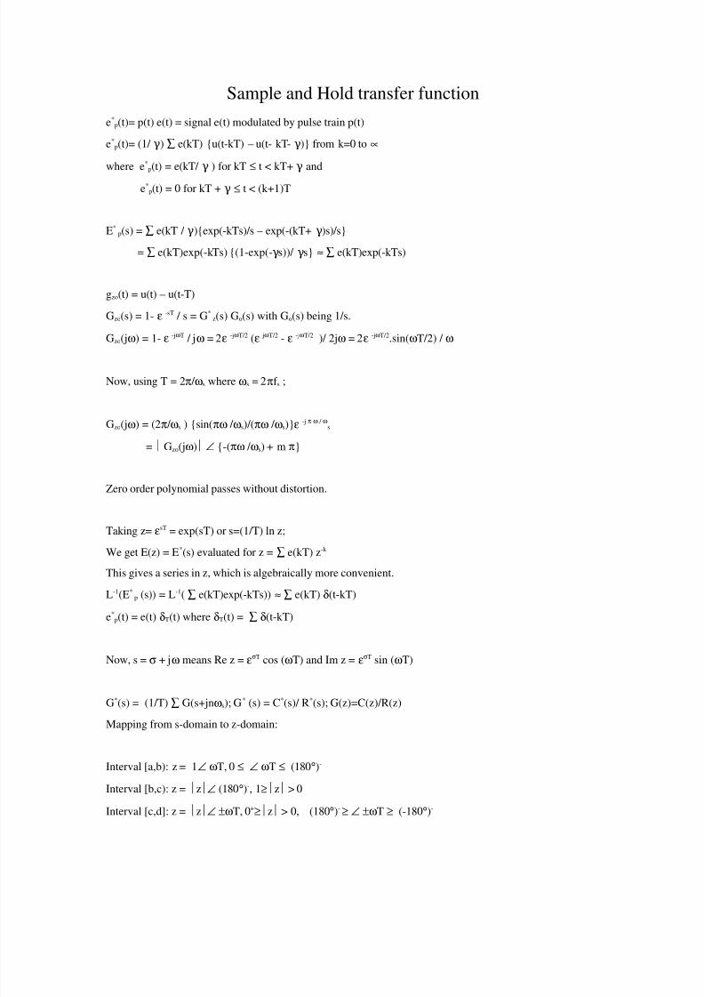
Sample and Hold transfer function
e*p(t)= p(t) e(t) = signal e(t) modulated by pulse train p(t)
e*p(t)= (1/ ) ∑ e(kT) {u(t-kT) – u(t- kT- )} from k=0 toγ γ ∝
where e*p(t) = e(kT/ ) for kTγ ≤ t < kT+ andγ
e*p(t) = 0 for kT + γ ≤ t < (k+1)T
E*p(s) = ∑ e(kT / ){exp(-kTs)/s – exp(-(kT+ )s)/s}γ γ
= ∑ e(kT)exp(-kTs) {(1-exp(- s))/ s}γ γ ≈ ∑ e(kT)exp(-kTs)
gzo(t) = u(t) – u(t-T)
Gzo(s) = 1- ε -sT / s = G*z(s) Go(s) with Go(s) being 1/s.
Gzo(jω) = 1- ε -jωT / jω = 2ε -jωT/2 (ε jωT/2 - ε -jωT/2 )/ 2jω = 2ε -jωT/2.sin(ωT/2) / ω
Now, using T = 2π / ωs where ωs = 2πf s ;
Gzo(jω) = (2π / ωs ) {sin(πω / ωs)/(πω / ωs)}ε -j π ω / ωs
= Gzo(jω) ∠ {-(πω / ωs) + m π}
Zero order polynomial passes without distortion.
Taking z= εsT = exp(sT) or s=(1/T) ln z;
We get E(z) = E*(s) evaluated for z = ∑ e(kT) z-k
This gives a series in z, which is algebraically more convenient.
L-1(E*p (s)) = L-1( ∑ e(kT)exp(-kTs)) ≈ ∑ e(kT) δ(t-kT)
e*p(t) = e(t) δT(t) where δT(t) = ∑ δ(t-kT)
Now, s = σ + jω means Re z = εσT cos (ωT) and Im z = εσT sin (ωT)
G*(s) = (1/T) ∑ G(s+jnωs); G* (s) = C*(s)/ R*(s); G(z)=C(z)/R(z)
Mapping from s-domain to z-domain:
Interval [a,b): z = 1∠ ωT, 0 ≤ ∠ ωT ≤ (180°)-
Interval [b,c): z = z∠ (180°)-, 1≥ z > 0
Interval [c,d]: z = z∠ ±ωT, 0+≥ z > 0, (180°)-≥ ∠ ±ωT ≥ (-180°)-
8/3/2019 Ccip Lessons
http://slidepdf.com/reader/full/ccip-lessons 11/34
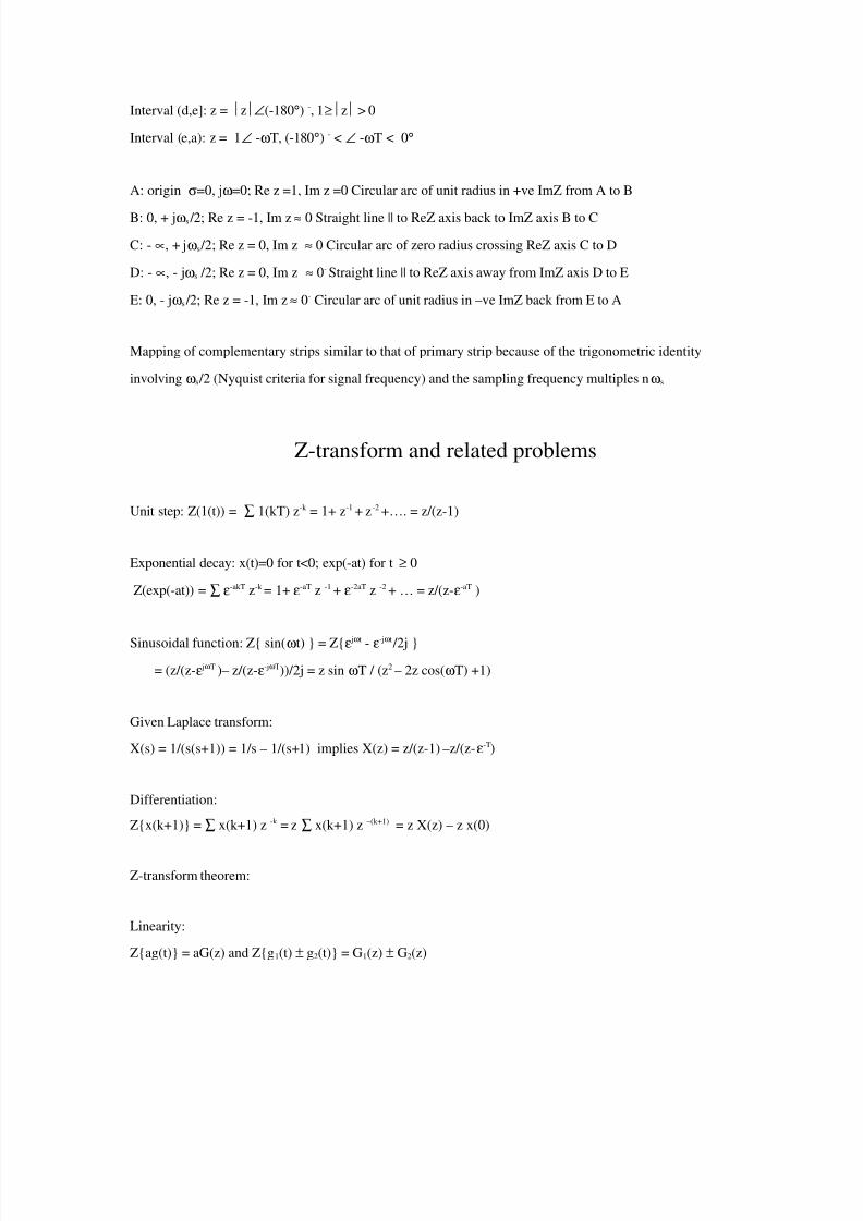
Interval (d,e]: z = z∠(-180°) -, 1≥ z > 0
Interval (e,a): z = 1∠ -ωT, (-180°) - < ∠ -ωT < 0°
A: origin σ=0, jω=0; Re z =1, Im z =0 Circular arc of unit radius in +ve ImZ from A to B
B: 0, + jωs /2; Re z = -1, Im z ≈ 0 Straight line || to ReZ axis back to ImZ axis B to C
C: - ∝, + jωs /2; Re z = 0, Im z ≈ 0 Circular arc of zero radius crossing ReZ axis C to D
D: - ∝, - jωs /2; Re z = 0, Im z ≈ 0- Straight line || to ReZ axis away from ImZ axis D to E
E: 0, - jωs /2; Re z = -1, Im z≈ 0- Circular arc of unit radius in –ve ImZ back from E to A
Mapping of complementary strips similar to that of primary strip because of the trigonometric identity
involving ωs /2 (Nyquist criteria for signal frequency) and the sampling frequency multiples nωs
Z-transform and related problems
Unit step: Z(1(t)) = ∑ 1(kT) z-k = 1+ z-1 + z-2 +…. = z/(z-1)
Exponential decay: x(t)=0 for t<0; exp(-at) for t ≥ 0
Z(exp(-at)) = ∑ ε-akT z-k = 1+ ε-aT z -1 + ε-2aT z -2 + … = z/(z-ε-aT )
Sinusoidal function: Z{ sin(ωt) } = Z{ε jωt - ε
-jωt /2j }
= (z/(z-ε jωT )– z/(z-ε-jωT))/2j = z sin ωT / (z2 – 2z cos(ωT) +1)
Given Laplace transform:
X(s) = 1/(s(s+1)) = 1/s – 1/(s+1) implies X(z) = z/(z-1) –z/(z-ε-T)
Differentiation:
Z{x(k+1)} = ∑ x(k+1) z -k = z ∑ x(k+1) z –(k+1) = z X(z) – z x(0)
Z-transform theorem:
Linearity:
Z{ag(t)} = aG(z) and Z{g1(t) ± g2(t)} = G1(z) ± G2(z)
8/3/2019 Ccip Lessons
http://slidepdf.com/reader/full/ccip-lessons 12/34
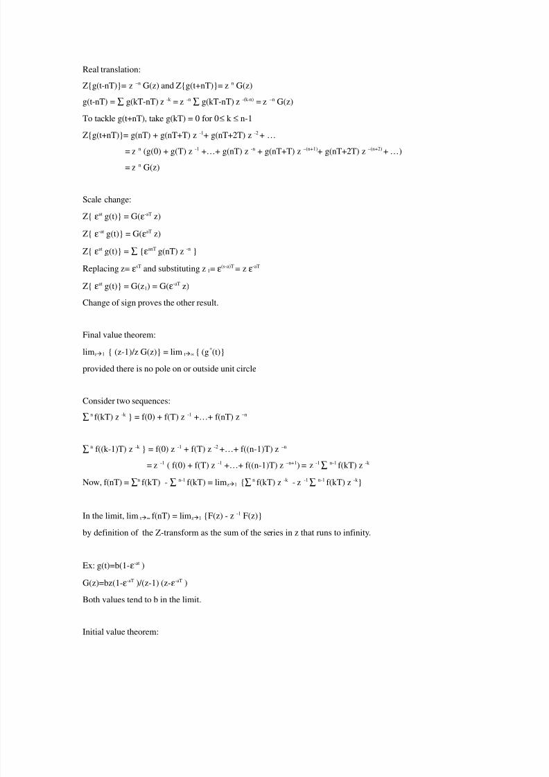
Real translation:
Z{g(t-nT)}= z –n G(z) and Z{g(t+nT)}= z n G(z)
g(t-nT) = ∑ g(kT-nT) z -k = z -n ∑ g(kT-nT) z -(k-n) = z –n G(z)
To tackle g(t+nT), take g(kT) = 0 for 0≤ k ≤ n-1
Z{g(t+nT)}= g(nT) + g(nT+T) z-1
+ g(nT+2T) z-2
+ …
= z n (g(0) + g(T) z -1 +…+ g(nT) z -n + g(nT+T) z –(n+1)+ g(nT+2T) z –(n+2) + …)
= z n G(z)
Scale change:
Z{ εat g(t)} = G(ε-aT z)
Z{ ε-at g(t)} = G(εaT z)
Z{ εat g(t)} = ∑ {εanT g(nT) z -n }
Replacing z= ε
sT
and substituting z 1= ε
(s-a)T
= z ε
-aT
Z{ εat g(t)} = G(z1) = G(ε-aT z)
Change of sign proves the other result.
Final value theorem:
limz1 { (z-1)/z G(z)} = lim t∝ { (g*(t)}
provided there is no pole on or outside unit circle
Consider two sequences:
∑ n f(kT) z -k } = f(0) + f(T) z -1 +…+ f(nT) z –n
∑ n f((k-1)T) z -k } = f(0) z -1 + f(T) z -2 +…+ f((n-1)T) z –n
= z -1 ( f(0) + f(T) z -1 +…+ f((n-1)T) z –n+1) = z -1∑ n-1 f(kT) z -k
Now, f(nT) = ∑n f(kT) - ∑ n-1 f(kT) = limz1 {∑ n f(kT) z -k - z -1∑ n-1 f(kT) z -k }
In the limit, lim t∝ f(nT) = limz1 {F(z) - z -1 F(z)}
by definition of the Z-transform as the sum of the series in z that runs to infinity.
Ex: g(t)=b(1-ε-at )
G(z)=bz(1-ε-aT )/(z-1) (z-ε-aT )
Both values tend to b in the limit.
Initial value theorem:
8/3/2019 Ccip Lessons
http://slidepdf.com/reader/full/ccip-lessons 13/34
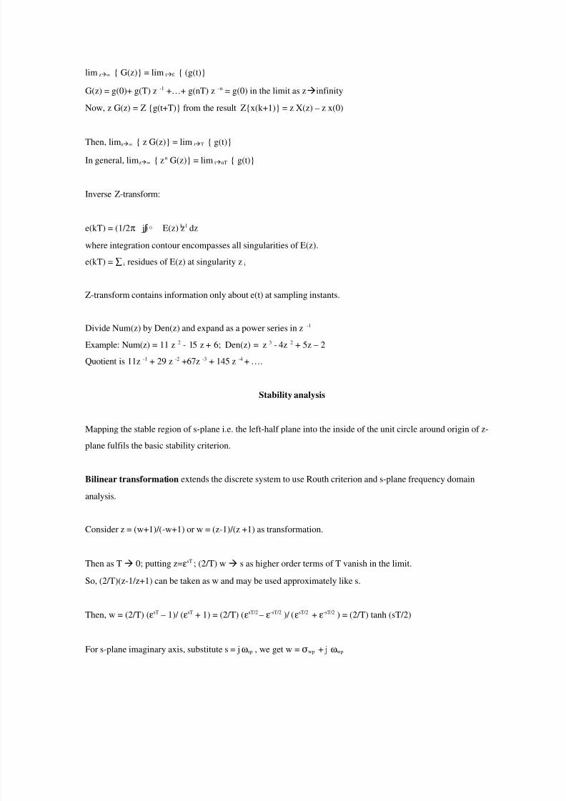
lim z∝ { G(z)} = lim t0 { (g(t)}
G(z) = g(0)+ g(T) z -1 +…+ g(nT) z –n = g(0) in the limit as zinfinity
Now, z G(z) = Z {g(t+T)} from the result Z{x(k+1)} = z X(z) – z x(0)
Then, limz∝ { z G(z)} = lim tT { g(t)}
In general, limz∝ { zn G(z)} = lim tnT { g(t)}
Inverse Z-transform:
e(kT) = (1/2π j) E(z) z∫◦ k-1 dz
where integration contour encompasses all singularities of E(z).
e(kT) = ∑ i residues of E(z) at singularity z i
Z-transform contains information only about e(t) at sampling instants.
Divide Num(z) by Den(z) and expand as a power series in z -1
Example: Num(z) = 11 z 2 - 15 z + 6; Den(z) = z 3 - 4z 2 + 5z – 2
Quotient is 11z -1 + 29 z -2 +67z -3 + 145 z -4 + ….
Stability analysis
Mapping the stable region of s-plane i.e. the left-half plane into the inside of the unit circle around origin of z-
plane fulfils the basic stability criterion.
Bilinear transformation extends the discrete system to use Routh criterion and s-plane frequency domain
analysis.
Consider z = (w+1)/(-w+1) or w = (z-1)/(z +1) as transformation.
Then as T 0; putting z=εsT ; (2/T) w s as higher order terms of T vanish in the limit.
So, (2/T)(z-1/z+1) can be taken as w and may be used approximately like s.
Then, w = (2/T) (εsT – 1)/ (εsT + 1) = (2/T) (εsT/2 – ε-sT/2 )/ (εsT/2 + ε-sT/2 ) = (2/T) tanh (sT/2)
For s-plane imaginary axis, substitute s = jωsp , we get w = σwp + j ωwp

8/3/2019 Ccip Lessons
http://slidepdf.com/reader/full/ccip-lessons 14/34
Then, w = (2/T) tanh ( jωsp T /2) = j(2/T) tan (ωspT/2)
If ωspT/2 is small, ωwp ≈ ωsp for ωspT/2 < 0.297
On real axis of s-plane, w = (2/T) tanh (σsp T/2) = σwp
Expand tanh(α) = (α +α 3 / 3! + ..)/(1+α 2 / 2! + ..)
For α 2 << 2; σsp ≈ σwp
Hence, for valid approximations, w s.≈
When not valid, pre-warping of s-plane poles and zeroes into w-plane through actual mapping has to be done.
The two planes are similar from stability analysis view point.
Applying Routh criterion to examine if any right half poles are present: Form the Routh array and no of rootswith positive real part is equal to the number of changes of sign in the first column. The necessary and sufficient
condition for all roots to lie in the left half s-plane is that all coefficients of the polynomial are positive and all
terms in the first column of the array have positive signs.
a0 sn + a1 sn-1 + … + an-1 s + an = 0
sn : a0 a2 a4 a6 ……..
sn-1 : a1 a3 a5 a7 ……..
sn-2 : b1 b2 b3 b4 ……..
sn-3 : c1 c2 c3 c4 ……..
sn-4 : d1 d2 d3 d4 ……..
s2 : e1 e2
s1 : f 1
s0 : g1
b1 = a1a2 -a0a3 / a1
b2 = a1a4 -a0a5 / a1
b3 = a1a6 -a0a7 / a1
…
c1 = b1a3 -a1b2 / b1
c2 = b1a5 -a1b3 / b1

8/3/2019 Ccip Lessons
http://slidepdf.com/reader/full/ccip-lessons 15/34
...
d1 = c1b2 -b1c2 / c1
d2 = c1b3 -b1c3 / c1
etc.
Since sign only matters, simplifications are allowed.
Ex. Q(z) = z3 - 4 z2 + 5z – 2 is characteristic equation with T = 2 sec.
Then, Q(w) = 12w3 - 4 w2
Upon substitution of z = (2/T) (w+1)/(-w+1) with denominator (1-w) 3
Routh table gives:
w3 : 12 0
w2: - 4 0
w1 : 0
w0 : 0
One change of sign can be seen in the first column => One root in the right half w-plane
Two zeroes in first column => Two roots on imaginary axis
In fact, Q(z) = (z-2) (z-1) 2
Ex. Q(z) = z3 – 0.8 z2 - 0.03z – 0.17 with T=2 sec.
Q(w) = w(1.94w2
+ 3.32 w + 2.74)
w2: 1.94 2.74
w1 : 3.32
w0 : 2.74
The root at w=0 => A root of Q(z) at z=1
Hence, step input will give ramp output.
System will be clearly stable with no change of sign.
Pseudo-continuous time (PCT) control system
Sampling introduces an attenuation factor of (1/T)
Pade Approximation:
F(x) A≈ m(x)/Bm(x) is a rational fraction approximation of a differentiable power series of the form
c0 + c1 x1 + c2 x2 + …where Am(x), Bm(x) are polynomials in x.

8/3/2019 Ccip Lessons
http://slidepdf.com/reader/full/ccip-lessons 16/34
First order Pade approximation of εx=1+x+ x2 /2!+ …yields
F(x) = (a0 + a1 x )/ (b0 + b1 x) = (1+x/2)/(1-x/2) by solving for a,b by comparing coefficients.
Now, Gzoh(s) = 1- ε -sT / s 2T/(Ts+2) using Pade approximation of first order.≈
Together with the sampler (1/T), the overall addition to the system TF is 2/(Ts+2)
As T0, ωs∞; 2/(Ts+2) 1
Hence, pseudo-continuous nature is observed.
Note that the second order Pade approximation of εx (1+x/2 + x≈ 2 /12)/ (1-x/2 + x2 /12)
So, poles of higher order would be introduced into the overall TF.
The main advantage is that all the analysis of continuous time system applies to the PCT.Interestingly, the role of sampling time T is evident as pole introduced contains it.
8/3/2019 Ccip Lessons
http://slidepdf.com/reader/full/ccip-lessons 17/34
From the state equations describing the system, one can write:
x(k+1) = F x(k) + H u(k)
z X(z) = F X(z) + H U(z)
X(z) = (z I – F)-1 H U(z)
x(1) = F x(0) + H u(0)
x(2) = F x(1) + H u(1) = F (F x(0) + H u(0) ) + H u(1)
= F2 x(0) + FH u(0) + H u(1)
x(n) = Fn x(0) + Fn-1 Hu(0) + Fn-2 H u(1) + … + H u(n-1)
= Fn x(0) + uΩ
= [H FH FΩ 2H … Fn-2 H Fn-1 H] is the state controllability matrix for linear time invariant systems.
y(k) = Cx(k) + Du(k)
y(k+1)= Cx(k+1) + Du(k+1) = C(Fx(k)+Hu(k))+Du(k+1)
= CF x(k) + CH u(k) + Du(k+1)
y(k+2) = CF2 x(k) + CFH u(k) + CH u(k+1) + D u(k+2)
y(k+N) = CF N x(k) + uΓ
= [CFΓ N -1 H CFN-2 H … CFH CH D] is the output controllability matrix for linear time invariant systems N
steps ahead.
Controllability criterion
No of state variables: n
No of input variables: r
No of output variables: p
State matrix F: n x n
Control (input) matrix H: n x r
Output matrix C: p x n
Feedforward matrix D: p x r

8/3/2019 Ccip Lessons
http://slidepdf.com/reader/full/ccip-lessons 18/34
The LTI system is completely state controllable iff
• The nXNr controllability matrix is of rank n.Ω
• The nxn matrix ΩΩ` (Gramian matrix) is non-singular.
• The rows of the matrix (z I – F)-1 H are linearly independent.
Proof: x(N) can be generated as linear combination of F i H iff has rank n. Therefore, each of u(i)’s areΩ
allowed to play a role in controlling the system from x(0) to x(N); which is the essence of controllability.
The LTI system is completely output controllable iff the matrix is of rank p.Γ
Feedback control law u(k) = -Kx(k) gives x(k+1) = [F-HK] x(k)
Q(z) = [zI-F+HK] = (z-p1) (z-p2) … (z-pn)
The desired poles are indicated in the design problem. The characteristic equation described above can then be
solved to find the required feedback gains K that ensure the desired pole placement.
Ackerman’s formula: K = [0 0 … 1] Ω -1 Q(F)
Every arbitrary initial state Final state using unconstrained control sequences
Strongly controllable: Each vector (discrete state or output) is controllable by a separate control, when all other
control inputs are zero.
Weakly controllable: Each vector is not strongly controllable.
Complete state controllability: Can find u(k i) for every initial state x(k 0) moves to any final state x(k N)
Complete output controllability: Every y(k 0) moves to any final y(k N)
Complete controllability: Control on every initial condition is implied.
Total controllability: additional control on k 0 and k N combination. For LTI systems both are same.
Reachability: Every state x(k N) can be reached from any x(k 0)
Reachable states: Subspace of state space and unconstrained controllers u(k i) with i = 0, 1, … , N-1; every state in
subspace can be reached.
Ex. F=[a b; c d] H=[g; h] D = [v]
n=2; r=1; p=1; N=2 (= n)
= [g ag+bh; h cg+dh]Ω
Det { } = cgΩ 2+dgh-agh-dh2 ≠0 is required for full rank.
8/3/2019 Ccip Lessons
http://slidepdf.com/reader/full/ccip-lessons 19/34
Say, a=0, b=1, c= -1, d =2, g = 1, h= -1.
Then = [ 1, -1; -1, 1]Ω
Det{ } = 0 implies system is uncontrollable.Ω
Subspace [1; -1] is reachable.
For time-varying systems, continued product { F (k Π i) } has to be considered.
= [Θ θ 0 θ1 … θN-1 ] where θi = F(k N-1) F(k N-2) … F(k i+1) H(k i) for i=0,1,…,N-1
is nxNr matrix of rank n in case of time varying systems.Θ
= [Ρ ρ 0 ρ1 … ρN-1] where ρi = C(k N)F(k N-1)F(k N-2) … F(k i+1) H(k i)
is matrix of rank p in case of time varying systems.Ρ
Observability criterion
All state variables are involved in feedback. If every initial state x(0) can be determined from the observation of y(t)
over a finite time interval – helps to reconstruct un-measurable state variables from the measured ones. Since u(kT)
are known, we use unforced system in the analysis.
Then all state variables can participate in feedback control.
x(k+1) = F x(k) and y(k) = C x(k) F n x n and C m x n
x(k) = Fk x(0) and y(k) = C Fk x(0)
Complete observability means given y(0), y(T), …, y(NT)
To determine x1(0), x2(0), …, xn(0)
y(0)= C x(0)
y(1)= CF x(0)
….
y(n-1) = C F n-1 x(0)
Arranging, y = Υx where Υ is the observability matrix nm x n which must have the full rank n so that the n
simultaneous equations may be solved
Ex. F=[a b; c d], C=[e; f], H=[g; h] D = [v]
n=2; r=1; p=1; N=2 (= n)
Υ = [e ae+cf; f be+df]
Det { Υ} = be2+def-aef-cf 2 ≠0 is required for full rank.
In other words,
x1(1) = a x1(0) + b x2(0)
x2(1) = c x1(0) + d x2(0)
y(0) = e x1(0) + f x2(0)

8/3/2019 Ccip Lessons
http://slidepdf.com/reader/full/ccip-lessons 20/34
y(1) = (ae+cf) x1(0) + (bc+df) x2(0)
We must be able to solve for x1(0) and x2(0) from these two simultaneous equations.
So the equations must be linearly independent.
Controllable Observable
Yes Yes Controller can be designed only in this case
Yes No
No Yes
No No
Controller and observer design
Since, x(k+1) = F x(k) + H u(k)
Taking u(k) = -K x(k) we have x(k+1) = (F-HK) x(k)
Taking Z-transform, z X(z) =(F-HK) X(z)
Simplifying, (zI-(F-HK) )-1 is the new state transition matrix.
Without controller it is (zI-F) -1
Characteristic equation Q(z) is obtained as determinant
So, the Eigenvalues have reduced through controller
Eigenvalues provide the new poles of the system.
From pole placement, one can solve for the controller gains K.
Ex. F = [1 0; 0 a] H = [1; -1] with a=0.815
Desired poles are given by Q(z) = (z-0.98)(z-0.85)
Then, K = [0.0162, 0.0312] can be obtained.
Desired closed-loop transfer function is recast in the selection of the desired pole locations of the closed-loop n-th
order characteristic equation Q(z). The unknown controller gains for this pole placement through feedback have
been obtained above.
Now consider a continuous system where output is observed, feedback is computed. Due to the computational delay,
the system states propagate by this time. To manage this, we need new mathematics.
Output at time k+1, given output at time k is denoted as (k+1|k)η
(k+1|k) = G (k|k-1)+Kη η oy y(k) + Kou u(k)
Here G , Koy , Kou are unknown matrices of proper dimension.
8/3/2019 Ccip Lessons
http://slidepdf.com/reader/full/ccip-lessons 21/34
(k+1|k) is a sequential reconstruction of of the state at time k+1η
given linear equations combining y and u at time k
Form the state at time k and value of forcing function at time k, we are predicting the state at time k+1
Error associated with prediction is e(k+1|k) = x(k+1) - (k+1|k)ηPutting x(k+1) = F x(k) + H u(k) and y(k) = C x(k) + D u(k)
We get e(k+1 | k) = (F - Koy C) x(k) – G (k | k-1) + (H- Kη oy D - Kou ) u(k)
Taking G = F - Koy C and Kou = H- Koy D, we get
Recursive relation e(k+1 | k) = G e(k | k-1)
Starting from an arbitrary initial error, whether the error converges depends on Gk
Since e(k|k-1) = G k [x(0) – y(0)]
Matrices F and C depend on system dynamics.
Using appropriate Koy , we can adjust G such that Gk 0 as k ∞
Here y(0) is a user-supplied initial condition.
The computation of the predictor output takes a finite time. This delay is to be managed.
Substituting G = F - Koy C and Kou = H- Koy D, we get
(k+1 | k) = F (k | k-1) + H u(k) + Kη η oy [y(k) – C (k | k-1) – D u(k)]η
F, H, C, D are obtained from system dynamics.
Koy and Kou are to be designed for error stability – this is essence of observer design.
Important:
Placement of Eigenvalues of G
Poles of the characteristic equation of G inside UC
Pole and zero cannot coincide, then order of system decreases and rank falls below n.
Specific selection of Eigenvalues depends on desired sensitivity of error.
Too much error sensitivity means faster reach to zero.
But this results in higher overshoot and settling time.
When objective is to bring the plant states to origin, F-HK are the regulator poles.
If both observer and regulator poles are assigned to the origin,
Observer reconstructs plant states in n steps,
Then regulator would be driving the states to origin in n steps.

8/3/2019 Ccip Lessons
http://slidepdf.com/reader/full/ccip-lessons 22/34
This is output feedback deadbeat control system.
Ex. Position control of a motor system
Given ẋ(t) = [0 1; 0 –a] x(t) + [0; b] u(t) and y(t) = [1 0] x(t)
Let a = 4.6 s-1 , b = 0.8 rad/volt s2 and T = 0.1 sec, delay = 0.02 sec.
= T – delay. Taking deadbeat controller, K = [1.16 7.14]τ
(t, tΦ 0) = [1, (1/a)*(1-exp(-a(t-t0)); 0, exp(-a(t- t0))]
F = [1 (1/a)*(1-exp(-aT); 0 exp(-aT)]
H = [(b/a)*(T-1/a + exp(-aT)/a; (b/a)*(1-exp(-aT))]
Cdiscrete = [1, (1/a)*(1-exp(-a ))]τ
Ddiscrete = ((b/a)*( – (1/a) – (exp(-a ))/a)τ τ
When = 0; observer form is (k | k-1)τ η
When = T; observer form is (k | k)τ η
Discrete system equation is x(k+1) = [1 0.08; 0 0.63]x(k) + [0.0034; 0.0631]u(k)
y η (k) = [1 0.066] (k)+ 0.0024 u(k)η
When = 0, u(k) plays no role.τ
y η (k) = [1 0] (k | k-1)η
Since the system is completely controllable, matrix F - Koy Cd with gain matrix [k 1 k 2]
Becomes [1- k 1 , 0.08-0.0661 k 1 ; - k 2 , 0.631 – 0.0661 k 2]
Setting the coefficients of characteristic equation to zero
For deadbeat controller gives K = [1.16 7.14]

8/3/2019 Ccip Lessons
http://slidepdf.com/reader/full/ccip-lessons 23/34
More details on discretization:
Concepts of estimation, prediction and smoothing
Introductory ideas of optimal, adaptive and stochastic control
1. Implementation of control system in industry
2. Basic concepts of microcontroller based implementation
3. Basic concepts of DSP based implementation
4. Basic concepts of PLC based implementation
8/3/2019 Ccip Lessons
http://slidepdf.com/reader/full/ccip-lessons 24/34
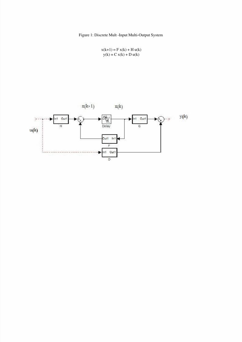
Figure 1: Discrete Mult -Input Multi-Output System
x(k+1) = F x(k) + H u(k)
y(k) = C x(k) + D u(k)
8/3/2019 Ccip Lessons
http://slidepdf.com/reader/full/ccip-lessons 25/34
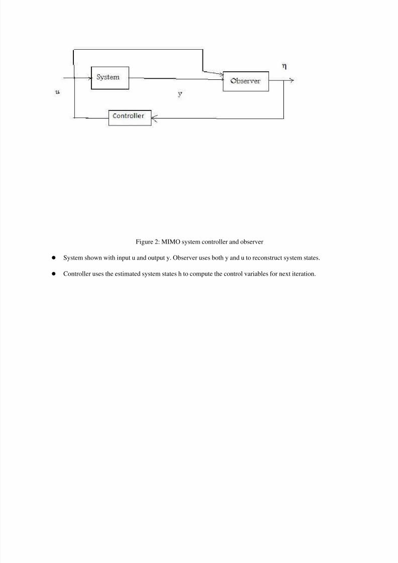
Figure 2: MIMO system controller and observer
System shown with input u and output y. Observer uses both y and u to reconstruct system states.
Controller uses the estimated system states h to compute the control variables for next iteration.
8/3/2019 Ccip Lessons
http://slidepdf.com/reader/full/ccip-lessons 26/34
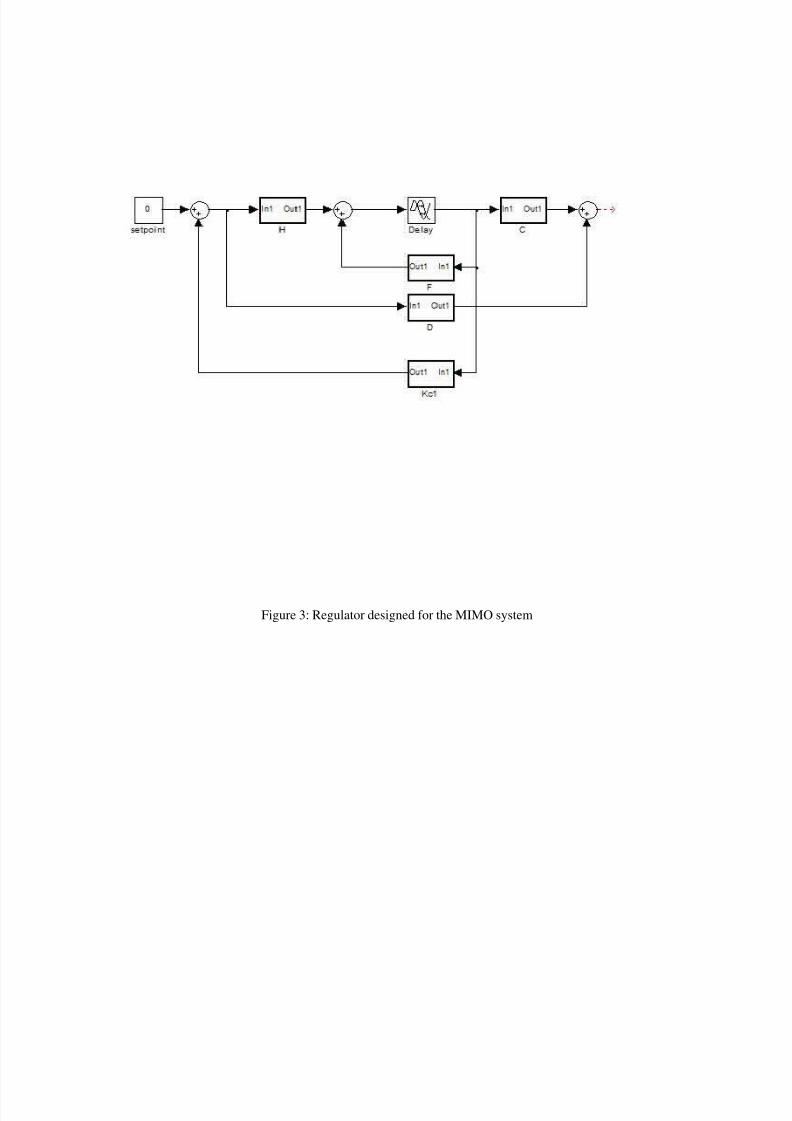
Figure 3: Regulator designed for the MIMO system
8/3/2019 Ccip Lessons
http://slidepdf.com/reader/full/ccip-lessons 27/34
Regulator design needs to track the zero inout set point. In optimal control, we need to find the admissible control
sequence that minimizes or maximizes a general performance index constrained by the linear time varying system
equation
x(k+1) = F(k) x(k) + H(k) u(k)
J = S{x(N),N} + S M{x(k), u(k), k}
for the entire zone of k=0 to (N-1)T.
S defines the terminal condition on the state x. S and M are bounded scalar functions that are at least first order
differentiable with respect to their arguments. This ensures a solution to the constrained optimization problem for the
cost function. Solve using Euler-Lagrange approach.
Jo = J – l' (k+1){x(k+1) - F(k) x(k) - H(k) u(k)} after augmenting the performance index with Lagrange multiplier.
Scalar Hamiltonian function involving first and last terms is maximum (min) along the optimal trajectory under the
discrete maximum (min) principle. Taking partial derivatives with respect to the independent variables and setting them
to zero results in equations for the optimal trajectory.
H[x(k), l(k+1), u(k), k] =
M{x(k), u(k), k} + l' (k+1) {F(k) x(k) + H(k) u(k)}
A common quadratic cost function is defined as follows:
Here, the rXr matrix R is symmetric and positive definite.
The nXn matrix Q symmetric and positive semi-definite.
J = (½) [x'(k) Q(k) x(k) + u'(k)R(k)u(k)] + ½ x'(N)S(N)x(N)
It represents the cost function in the form of general energy constraint on the system state and controller. The problem is
known as linear quadratic regulator problem (LQR)
Taking l(k) = P(k) x(k) as a solution after putting appropriate boundary conditions,
u(k) = -R-1 (k)H'(k)l(k+1) and upon substituting this along with assumed form of l;
x(k+1) = [I+H(k)R-1 (k)H'(k)P(k+1)]-1 F(k) x(k)
or, F'(k) P(k+1) x(k+1) = [P(k) – Q(k)] x(k)
Finally,
P(k) = Q(k) + F'(k)P(k+1) [I + H(k)R-1 (k)H'(k)P(k+1)]-1 F(k)
The controller equation can now be obtained as:
u(k) = -[R+H'(k)P(k+1)H(k)]-1 H'(k)P(k+1)F(k)x(k) = Kc(k) x(k)
Other forms of P(k) involving Kc can also be derived.
P(k)=[F HKc(k)]' P(k+1)[F HKc(k)] + Q + Kc'(k)RKc(k)
Kc is called the optimal feedback gain matrix or Kalman gain.
Eqn for P(k) is called the Riccati equation and
P(k) is called the Riccati gain matrix.
The unknown nXn elements of symmetric matrix P(k)can be solved from n(n-1) equations.
Stability of state-space systems:
8/3/2019 Ccip Lessons
http://slidepdf.com/reader/full/ccip-lessons 28/34
Let V(x) = x'Px be a Lyapunov function
such that V(x) is positive definite,
V(0)=0 and V(x) is continuous in x.
V(Fx)-V(x) = (Fx)'PFx-x'Px =x'[F'PF-P]x = -x'Qx
Here F'PF-P = -Q is a positive definite matrix
that must exist for asymptotic stability.
In the current problem, in presence of controller,
DV(x) = x'(k+1)P(k+1) x(k+1) - x'(k)P(k)x(k)
= x'(k)[F-HKc]'P(k+1)[F-HKc]x(k) – x'(k)P(k)x(k)
= -(Q+Kc'RKc) which is negative definite.
Now DV(x) is negative definite implies that the system is asymptotically stable. (Lyapunov's second method)
Diagonal elements of R and Q weighting matrices determine the pole placement in the z domain.
8/3/2019 Ccip Lessons
http://slidepdf.com/reader/full/ccip-lessons 29/34
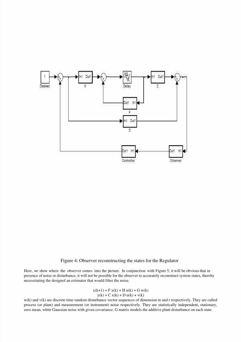
Figure 4: Observer reconstructing the states for the Regulator
Here, we show where the observer comes into the picture. In conjunction with Figure 5, it will be obvious that in
presence of noise or disturbance, it will not be possible for the observer to accurately reconstruct system states, thereby
necessitating the designof an estimator that would filter the noise.
x(k+1) = F x(k) + H u(k) + G w(k)
y(k) = C x(k) + D u(k) + v(k)
w(k) and v(k) are discrete time random disturbance vector sequences of dimension m and r respectively. They are calledprocess (or plant) and measurement (or instrument) noise respectively. They are statistically independent, stationary,
zero mean, white Gaussian noise with given covariance. G matrix models the additive plant disturbance on each state.
8/3/2019 Ccip Lessons
http://slidepdf.com/reader/full/ccip-lessons 30/34
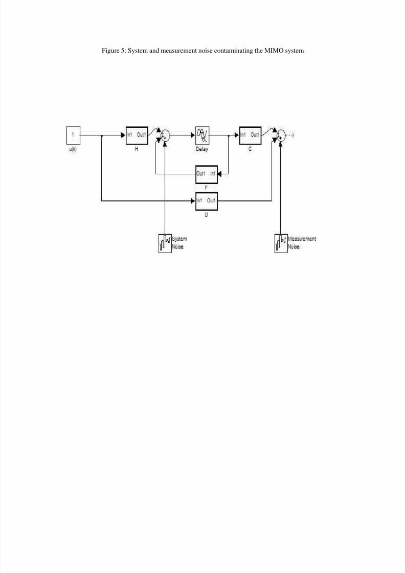
Figure 5: System and measurement noise contaminating the MIMO system

8/3/2019 Ccip Lessons
http://slidepdf.com/reader/full/ccip-lessons 31/34
Formulation of the estimator problem:
J=(½) E[{x(k+k) – x^(k+k | k)}'{x(k+k) – x^(k+k | k)}]
where x(k+k) –x^(k+k | k) represents the estimation error and J gives the least square norm.
Here, x^(k+k | k) is the best estimate for measurements [y(k N), y(k N-1), ..., y(k 0)] and control inputs [u(k i)]
If k is zero, then it is called filtering problem.
If k > 0, then it is called prediction problem.
If k < 0, then it is called smoothing problem.
x^(k+1|k) = Fx^(k|k-1) + Kf (k) [y(k) - Cx^(k|k-1)]
Kf (k) is called the Kalman estimator gain. It can be generated from the Riccati equations.
P(k | k) = P(k | k-1) –
P(k| k-1)C'[V+CP(k | k-1)C']-1 CP(k | k-1)
P(k+1 | k) = F P(k | k) F' + GWG'
Kf (k) = P(k | k) C' V -1
Each application requires detailed study of covariance matrix W, V and Kalman gain matrix K f .
8/3/2019 Ccip Lessons
http://slidepdf.com/reader/full/ccip-lessons 32/34
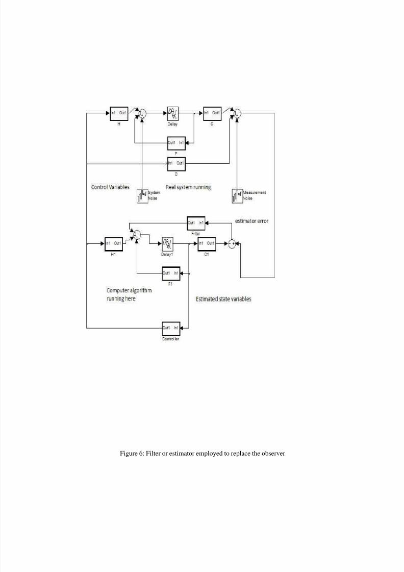
Figure 6: Filter or estimator employed to replace the observer
8/3/2019 Ccip Lessons
http://slidepdf.com/reader/full/ccip-lessons 33/34
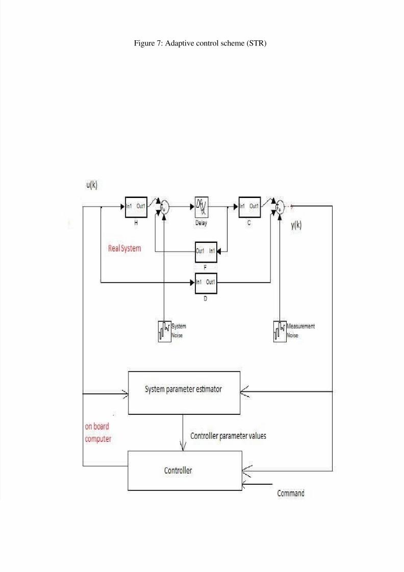
Adaptive controller schemes
Self tuning regulator:
Adjust the system parameters using the following algorithm:
1. Recursively identify/ estimate the value of selected parameters based upon measurements y(i) and input u(i) for
i =0, 1 ..., k-1
2. Update discrete controller difference equation coefficients. In case of state-space models, update appropriate
matrix values.
3. Generate control value u(k)
4. Repeat the process
Model reference adaptive control system:
This is similar to STR, differs in the technique for adjusting the controller. A given apriori model for which the
controller was designed is used as reference. It is driven with the identical input to the plant. The two outputs are
compared and the error is driven to zero by using it to modify the controller dynamics.
Gain scheduling:
When mode of the process changes, different gains are utilized depending on the performance requirements of each
mode. A particular mode plant model may be of different order due to exciting of additional dynamics.
In nonlinear systems, extensive simulation is needed to examine stability and desired performance. Parameter sensitivity
is a major challenge to successful implementation of adaptive control.
8/3/2019 Ccip Lessons
http://slidepdf.com/reader/full/ccip-lessons 34/34
Figure 7: Adaptive control scheme (STR)