Embed Size (px)
Citation preview
Wear 290–291 (2012) 154–160
Contents lists available at SciVerse ScienceDirect
Wear
0043-16
http://d
n Corr
E-m
journal homepage: www.elsevier.com/locate/wear
Cavitation in impacted drops and jets and the effect on erosiondamage thresholds
J.E. Field a,n, J.-J. Camus a, M. Tinguely b, D. Obreschkow c, M. Farhat b
a Cavendish Laboratory, University of Cambridge, Department of Physics, JJ Thomson Avenue, Cambridge CB3 0HE, UKb EPF Lausanne, Switzerlandc The University of Western Australia, ICRAR, Crawley, WA 6009, Australia
a r t i c l e i n f o
Article history:
Received 10 October 2011
Received in revised form
23 March 2012
Accepted 27 March 2012Available online 28 May 2012
Keywords:
Cavitation
Erosion
High-speed photography
48/$ - see front matter & 2012 Elsevier B.V. A
x.doi.org/10.1016/j.wear.2012.03.006
esponding author.
ail addresses: [email protected], karen@
a b s t r a c t
It is well known that metals and alloys erode at lower impact threshold velocities than expected. This
was studied by Thomas and Brunton (1970) [1] who reported ‘‘discrepancy factors’’ in the range 4–10.
These authors suggested that liquid impact was a more searching impact than solid impact since it was
able to exploit weaknesses in the metal. Further, as erosion develops the sideways liquid flow can add
shear stresses to surface steps and hydraulically load liquid trapped in cracks and crevices. In 1970,
Brunton and Camus [2,3] showed that during the impact process cavities could form inside the liquid
drops, and that some collapsed onto the solid surface. This provided a second potential mechanism to
explain the low damage threshold with the cavity collapse adding to the ‘‘water hammer’’ pressures.
However, Brunton and Camus were cautious in offering this as a potential mechanism. In this paper, we
argue that the Brunton and Camus experiments were in a relatively low velocity regime (20–70 m s�1),
compared with those in turbine erosion and rain erosion of aircraft components. This paper presents
high-speed photographic sequences of cavity formation and shock propagation in impacted liquids
using a range of techniques. Finally, a new method is described in which a metal projectile is fired at a
liquid jet. This produces large amounts of cavitation. Our conclusion is that the cavity collapse process
can explain the observed lower threshold velocities.
& 2012 Elsevier B.V. All rights reserved.
1. Introduction
When water drops impact a surface above a threshold velocitythey can eventually lead to erosion. Important practical situationsare erosion of blades in a steam turbine, erosion of forward-facingcomponents on an aircraft, and erosion of hydraulic machineryincluding ships propellers. Underwater blast on composite sand-wich panels and tubular laminated structures also has increasingpractical interest [4]. The main erosion mechanisms have beenidentified by Engel [5], Bowden and Brunton [6] and Bowden andField [7]. As the surface becomes roughened by the erosion moremechanisms operate, for example sideways flowing liquid appliesshear to surface steps, liquid in crevices is pressurised, etc. [8].The reader can obtain a general background of erosion throughthe volumes edited by Preece [9], Adler [10] and the series ofinternational conferences on ‘‘Erosion by Liquid and Solid Impact’’(ELSI) [11,12]. Significant advances to the theory of liquid/solidimpact were made by Lesser [13]. A review of the impact ofcompressible liquids covering both theory and experiment can befound in [14].
ll rights reserved.
mrao.cam.ac.uk (J.E. Field).
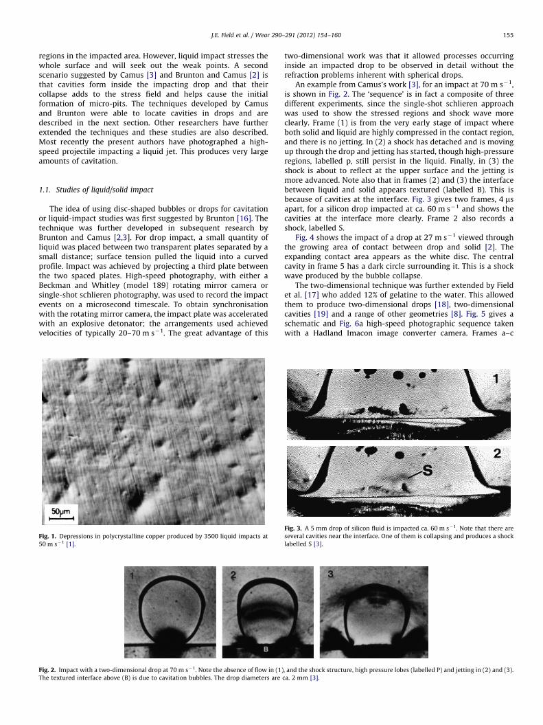
However, what is of particular interest is the very early stagesof erosion when most metals form small plastic depressionsrandomly distributed throughout the impact area; see, for exam-ple, [1,15] and Fig. 1. The features develop at stresses which aresmaller than the expected yield stress. Thomas and Brunton [1]have studied this in detail and have shown that what they call the‘‘discrepancy factor’’ various from 4 for softer metals such ascopper to at least 10 for a high strength steel.
The apparatus used by Thomas and Brunton for studyingrepeated liquid impact was a wheel and jet apparatus. Specimenswere attached to the rim of a disc which was rotated by high speed.The leading edges of the specimen cut through a 1.5 mm diametercylindrical water jet flowing parallel to the axis of rotation. Samplesof metals and alloys were eroded at 125 m s�1. The stressesachieved at this velocity can be calculated from liquid impact theory(see the appendix). The ‘water hammer’ pressure for 125 m s�1
impacts is �190 MPa. This pressure is at the low end of the metals’and alloys’ yield strengths which fell in the range 150 MPa (highpurity aluminium) up to 700 MPa (cobalt). More details can befound in [1].
Two main explanations for this phenomenon have been putforward. The first of these by Thomas and Brunton [1] emphasisesthe differences between a solid impactor and a liquid one. When asolid indenter is involved, the load is taken up by the stronger
J.E. Field et al. / Wear 290–291 (2012) 154–160 155
regions in the impacted area. However, liquid impact stresses thewhole surface and will seek out the weak points. A secondscenario suggested by Camus [3] and Brunton and Camus [2] isthat cavities form inside the impacting drop and that theircollapse adds to the stress field and helps cause the initialformation of micro-pits. The techniques developed by Camusand Brunton were able to locate cavities in drops and aredescribed in the next section. Other researchers have furtherextended the techniques and these studies are also described.Most recently the present authors have photographed a high-speed projectile impacting a liquid jet. This produces very largeamounts of cavitation.
1.1. Studies of liquid/solid impact
The idea of using disc-shaped bubbles or drops for cavitationor liquid-impact studies was first suggested by Brunton [16]. Thetechnique was further developed in subsequent research byBrunton and Camus [2,3]. For drop impact, a small quantity ofliquid was placed between two transparent plates separated by asmall distance; surface tension pulled the liquid into a curvedprofile. Impact was achieved by projecting a third plate betweenthe two spaced plates. High-speed photography, with either aBeckman and Whitley (model 189) rotating mirror camera orsingle-shot schlieren photography, was used to record the impactevents on a microsecond timescale. To obtain synchronisationwith the rotating mirror camera, the impact plate was acceleratedwith an explosive detonator; the arrangements used achievedvelocities of typically 20–70 m s�1. The great advantage of this
Fig. 1. Depressions in polycrystalline copper produced by 3500 liquid impacts at
50 m s�1 [1].
Fig. 2. Impact with a two-dimensional drop at 70 m s�1. Note the absence of flow in (1)
The textured interface above (B) is due to cavitation bubbles. The drop diameters are
two-dimensional work was that it allowed processes occurringinside an impacted drop to be observed in detail without therefraction problems inherent with spherical drops.
An example from Camus’s work [3], for an impact at 70 m s�1,is shown in Fig. 2. The ‘sequence’ is in fact a composite of threedifferent experiments, since the single-shot schlieren approachwas used to show the stressed regions and shock wave moreclearly. Frame (1) is from the very early stage of impact whereboth solid and liquid are highly compressed in the contact region,and there is no jetting. In (2) a shock has detached and is movingup through the drop and jetting has started, though high-pressureregions, labelled p, still persist in the liquid. Finally, in (3) theshock is about to reflect at the upper surface and the jetting ismore advanced. Note also that in frames (2) and (3) the interfacebetween liquid and solid appears textured (labelled B). This isbecause of cavities at the interface. Fig. 3 gives two frames, 4 msapart, for a silicon drop impacted at ca. 60 m s�1 and shows thecavities at the interface more clearly. Frame 2 also records ashock, labelled S.
Fig. 4 shows the impact of a drop at 27 m s�1 viewed throughthe growing area of contact between drop and solid [2]. Theexpanding contact area appears as the white disc. The centralcavity in frame 5 has a dark circle surrounding it. This is a shockwave produced by the bubble collapse.
The two-dimensional technique was further extended by Fieldet al. [17] who added 12% of gelatine to the water. This allowedthem to produce two-dimensional drops [18], two-dimensionalcavities [19] and a range of other geometries [8]. Fig. 5 gives aschematic and Fig. 6a high-speed photographic sequence takenwith a Hadland Imacon image converter camera. Frames a–c
, and the shock structure, high pressure lobes (labelled P) and jetting in (2) and (3).
ca. 2 mm [3].
Fig. 3. A 5 mm drop of silicon fluid is impacted ca. 60 m s�1. Note that there are
several cavities near the interface. One of them is collapsing and produces a shock
labelled S [3].

Fig. 4. The impact of a pendant drop at 27 m s�1 as viewed through the
expanding contact area between drop and solid. The frames are at 0, 4, 6, 8, 10
and 12 ms. Several cavities appear and later collapse. The central cavity also
produces a visible shock wave [2].
Fig. 5. Top view of the impact geometry. D is the drop and S is the impacting
slider. A Hadland Imacon camera is triggered when the laser beam is interrupted.
Fig. 6. Impact of 10 mm diameter water drop by a metal slider at a velocity of
110 m s�1. The onset of jetting is visible in frame c and labelled J is frame d. The
shock, labelled R, reflects in frame i and focuses, labelled F, in frame j. This
cavitation is too far from the solid to cause damage. The roughening at the
interface is also caused by cavitation. Interframe time is 1 ms [18].
J.E. Field et al. / Wear 290–291 (2012) 154–160156
show the early stage when the contact area is supersonic andthere is no flow. In frame, (d) jetting starts. A shock which travelsup through the liquid reflects at R, and focuses at F in frame (j).This is too far from the solid to cause damage. However, there isroughening at the liquid/solid interface which is wherecavities form.
The mechanism for the production of cavities in this situationwas proposed by Field et al. [17] based on Lesser’s acoustic model[13] and is illustrated in Fig. 7. The release waves (dotted)superpose when they cross, bringing the liquid into a tensile-stress state causing cavitation.
1.2. Studies of liquid/liquid impact
It is well-known that when a cavity collapses near a solidsurface, an internal jet is produced which crosses the cavity andimpacts the far side [20,21]. A jet also forms when a shock passesover a cavity with the jet produced in the direction of the shock(see, for example, [19]). What is less understood is the behaviourwhen the jet impacts the liquid on the far side of the cavity.
In a review of liquid impact [14], Lesser and Field describe howwater jets can be produced of millimetre diameter and withvelocities up to �1000 m s�1. This equipment was used byBourne et al. [22] to study 3 mm diameter jets impacting waterat 400–600 m s�1. The behaviour was followed using an UltranacFS501 programmable image converter camera operated in bothstreak and framing modes. The view observed by the camera isshown schematically in Fig. 8 and a sequence of frames in Fig. 9.
On impact, a system of shock and release waves is set up in thewater illustrated in the enlargement of Fig. 8. A shock wave S istransmitted into the stationary water, while a shock S0 travelsback into the jet decelerating the liquid flowing downward. Theshocks are followed by rarefaction waves R and R0 which come in
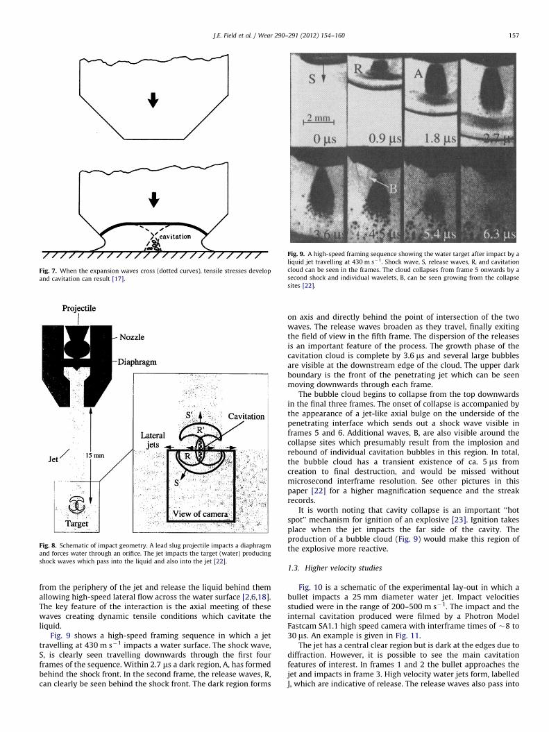
Fig. 8. Schematic of impact geometry. A lead slug projectile impacts a diaphragm
and forces water through an orifice. The jet impacts the target (water) producing
shock waves which pass into the liquid and also into the jet [22].
Fig. 7. When the expansion waves cross (dotted curves), tensile stresses develop
and cavitation can result [17].
Fig. 9. A high-speed framing sequence showing the water target after impact by a
liquid jet travelling at 430 m s�1. Shock wave, S, release waves, R, and cavitation
cloud can be seen in the frames. The cloud collapses from frame 5 onwards by a
second shock and individual wavelets, B, can be seen growing from the collapse
sites [22].
J.E. Field et al. / Wear 290–291 (2012) 154–160 157
from the periphery of the jet and release the liquid behind themallowing high-speed lateral flow across the water surface [2,6,18].The key feature of the interaction is the axial meeting of thesewaves creating dynamic tensile conditions which cavitate theliquid.
Fig. 9 shows a high-speed framing sequence in which a jettravelling at 430 m s�1 impacts a water surface. The shock wave,S, is clearly seen travelling downwards through the first fourframes of the sequence. Within 2.7 ms a dark region, A, has formedbehind the shock front. In the second frame, the release waves, R,can clearly be seen behind the shock front. The dark region forms
on axis and directly behind the point of intersection of the twowaves. The release waves broaden as they travel, finally exitingthe field of view in the fifth frame. The dispersion of the releasesis an important feature of the process. The growth phase of thecavitation cloud is complete by 3.6 ms and several large bubblesare visible at the downstream edge of the cloud. The upper darkboundary is the front of the penetrating jet which can be seenmoving downwards through each frame.
The bubble cloud begins to collapse from the top downwardsin the final three frames. The onset of collapse is accompanied bythe appearance of a jet-like axial bulge on the underside of thepenetrating interface which sends out a shock wave visible inframes 5 and 6. Additional waves, B, are also visible around thecollapse sites which presumably result from the implosion andrebound of individual cavitation bubbles in this region. In total,the bubble cloud has a transient existence of ca. 5 ms fromcreation to final destruction, and would be missed withoutmicrosecond interframe resolution. See other pictures in thispaper [22] for a higher magnification sequence and the streakrecords.
It is worth noting that cavity collapse is an important ‘‘hotspot’’ mechanism for ignition of an explosive [23]. Ignition takesplace when the jet impacts the far side of the cavity. Theproduction of a bubble cloud (Fig. 9) would make this region ofthe explosive more reactive.
1.3. Higher velocity studies
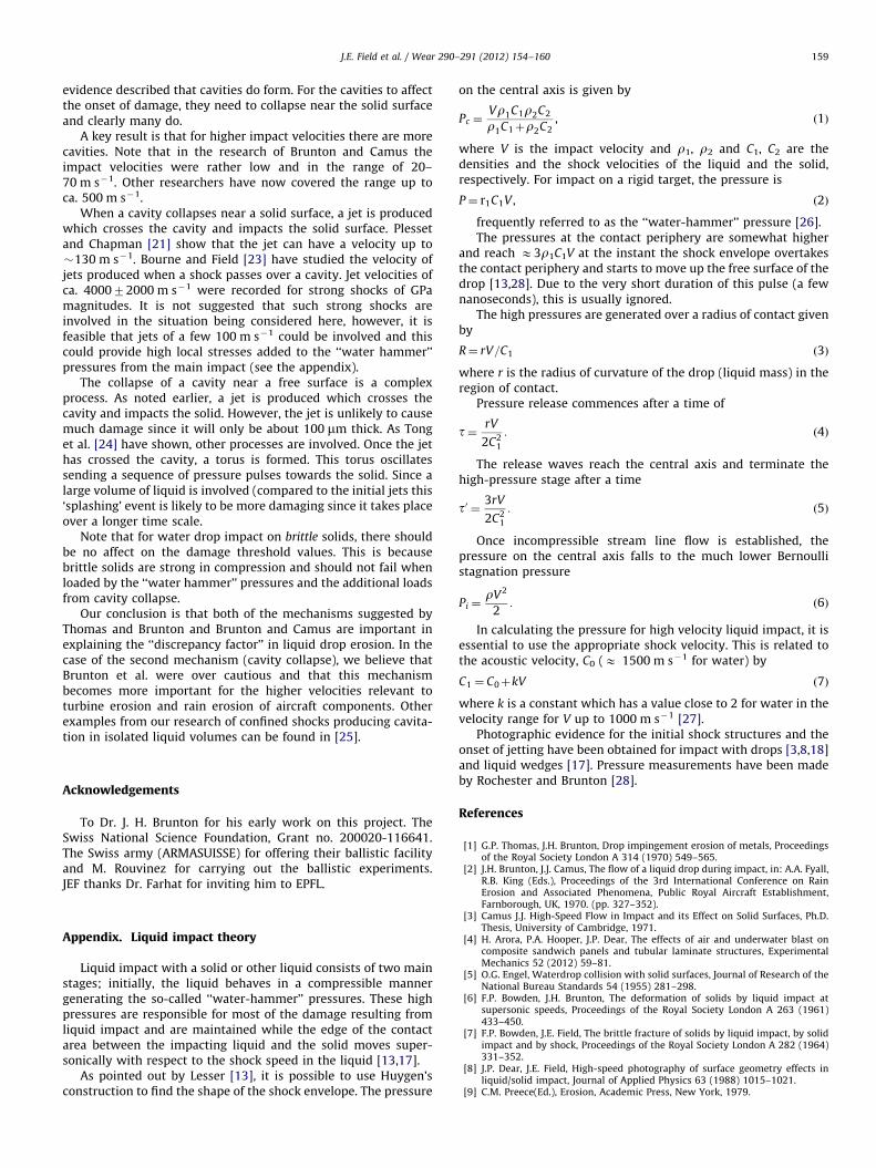
Fig. 10 is a schematic of the experimental lay-out in which abullet impacts a 25 mm diameter water jet. Impact velocitiesstudied were in the range of 200–500 m s�1. The impact and theinternal cavitation produced were filmed by a Photron ModelFastcam SA1.1 high speed camera with interframe times of �8 to30 ms. An example is given in Fig. 11.
The jet has a central clear region but is dark at the edges due todiffraction. However, it is possible to see the main cavitationfeatures of interest. In frames 1 and 2 the bullet approaches thejet and impacts in frame 3. High velocity water jets form, labelledJ, which are indicative of release. The release waves also pass into
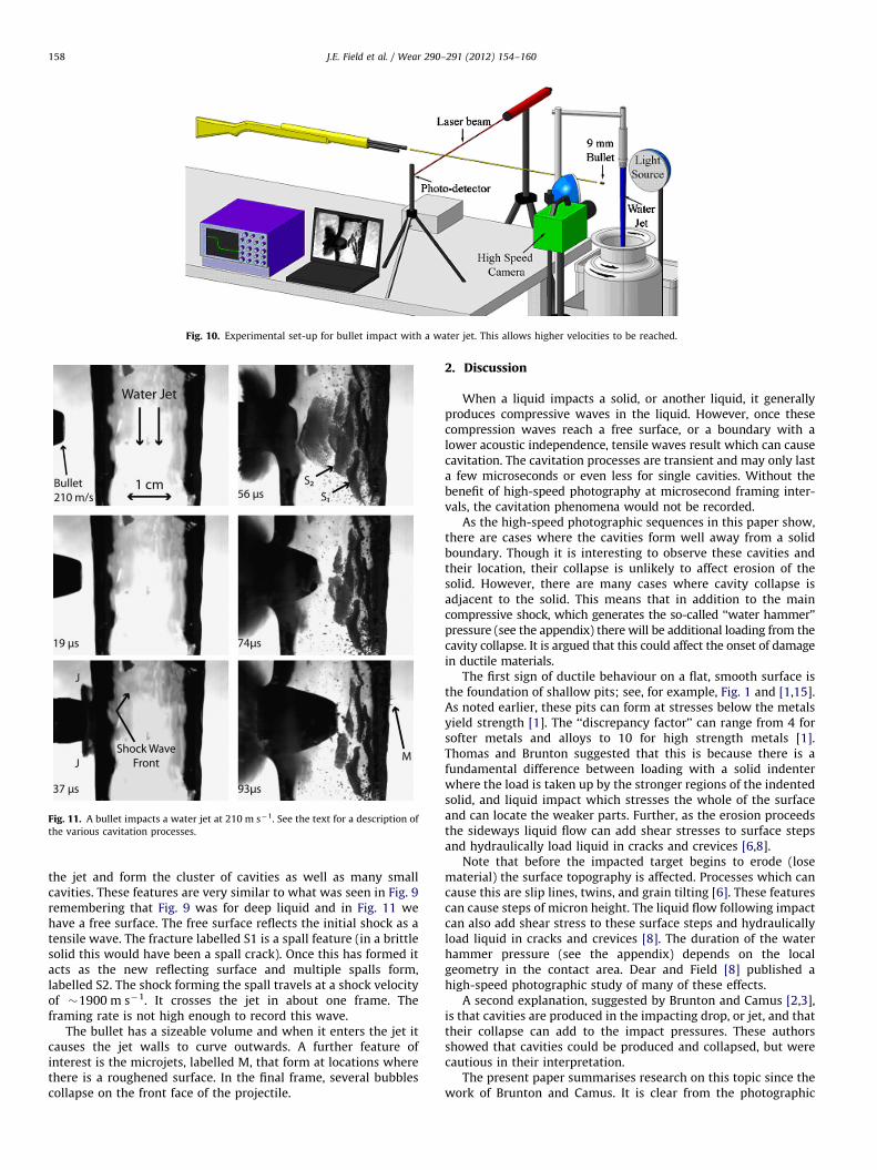
Fig. 10. Experimental set-up for bullet impact with a water jet. This allows higher velocities to be reached.
Fig. 11. A bullet impacts a water jet at 210 m s�1. See the text for a description of
the various cavitation processes.
J.E. Field et al. / Wear 290–291 (2012) 154–160158
the jet and form the cluster of cavities as well as many smallcavities. These features are very similar to what was seen in Fig. 9remembering that Fig. 9 was for deep liquid and in Fig. 11 wehave a free surface. The free surface reflects the initial shock as atensile wave. The fracture labelled S1 is a spall feature (in a brittlesolid this would have been a spall crack). Once this has formed itacts as the new reflecting surface and multiple spalls form,labelled S2. The shock forming the spall travels at a shock velocityof �1900 m s�1. It crosses the jet in about one frame. Theframing rate is not high enough to record this wave.
The bullet has a sizeable volume and when it enters the jet itcauses the jet walls to curve outwards. A further feature ofinterest is the microjets, labelled M, that form at locations wherethere is a roughened surface. In the final frame, several bubblescollapse on the front face of the projectile.
2. Discussion
When a liquid impacts a solid, or another liquid, it generallyproduces compressive waves in the liquid. However, once thesecompression waves reach a free surface, or a boundary with alower acoustic independence, tensile waves result which can causecavitation. The cavitation processes are transient and may only lasta few microseconds or even less for single cavities. Without thebenefit of high-speed photography at microsecond framing inter-vals, the cavitation phenomena would not be recorded.
As the high-speed photographic sequences in this paper show,there are cases where the cavities form well away from a solidboundary. Though it is interesting to observe these cavities andtheir location, their collapse is unlikely to affect erosion of thesolid. However, there are many cases where cavity collapse isadjacent to the solid. This means that in addition to the maincompressive shock, which generates the so-called ‘‘water hammer’’pressure (see the appendix) there will be additional loading from thecavity collapse. It is argued that this could affect the onset of damagein ductile materials.
The first sign of ductile behaviour on a flat, smooth surface isthe foundation of shallow pits; see, for example, Fig. 1 and [1,15].As noted earlier, these pits can form at stresses below the metalsyield strength [1]. The ‘‘discrepancy factor’’ can range from 4 forsofter metals and alloys to 10 for high strength metals [1].Thomas and Brunton suggested that this is because there is afundamental difference between loading with a solid indenterwhere the load is taken up by the stronger regions of the indentedsolid, and liquid impact which stresses the whole of the surfaceand can locate the weaker parts. Further, as the erosion proceedsthe sideways liquid flow can add shear stresses to surface stepsand hydraulically load liquid in cracks and crevices [6,8].
Note that before the impacted target begins to erode (losematerial) the surface topography is affected. Processes which cancause this are slip lines, twins, and grain tilting [6]. These featurescan cause steps of micron height. The liquid flow following impactcan also add shear stress to these surface steps and hydraulicallyload liquid in cracks and crevices [8]. The duration of the waterhammer pressure (see the appendix) depends on the localgeometry in the contact area. Dear and Field [8] published ahigh-speed photographic study of many of these effects.
A second explanation, suggested by Brunton and Camus [2,3],is that cavities are produced in the impacting drop, or jet, and thattheir collapse can add to the impact pressures. These authorsshowed that cavities could be produced and collapsed, but werecautious in their interpretation.
The present paper summarises research on this topic since thework of Brunton and Camus. It is clear from the photographic
J.E. Field et al. / Wear 290–291 (2012) 154–160 159
evidence described that cavities do form. For the cavities to affectthe onset of damage, they need to collapse near the solid surfaceand clearly many do.
A key result is that for higher impact velocities there are morecavities. Note that in the research of Brunton and Camus theimpact velocities were rather low and in the range of 20–70 m s�1. Other researchers have now covered the range up toca. 500 m s�1.
When a cavity collapses near a solid surface, a jet is producedwhich crosses the cavity and impacts the solid surface. Plessetand Chapman [21] show that the jet can have a velocity up to�130 m s�1. Bourne and Field [23] have studied the velocity ofjets produced when a shock passes over a cavity. Jet velocities ofca. 400072000 m s�1 were recorded for strong shocks of GPamagnitudes. It is not suggested that such strong shocks areinvolved in the situation being considered here, however, it isfeasible that jets of a few 100 m s�1 could be involved and thiscould provide high local stresses added to the ‘‘water hammer’’pressures from the main impact (see the appendix).
The collapse of a cavity near a free surface is a complexprocess. As noted earlier, a jet is produced which crosses thecavity and impacts the solid. However, the jet is unlikely to causemuch damage since it will only be about 100 mm thick. As Tonget al. [24] have shown, other processes are involved. Once the jethas crossed the cavity, a torus is formed. This torus oscillatessending a sequence of pressure pulses towards the solid. Since alarge volume of liquid is involved (compared to the initial jets this‘splashing’ event is likely to be more damaging since it takes placeover a longer time scale.
Note that for water drop impact on brittle solids, there shouldbe no affect on the damage threshold values. This is becausebrittle solids are strong in compression and should not fail whenloaded by the ‘‘water hammer’’ pressures and the additional loadsfrom cavity collapse.
Our conclusion is that both of the mechanisms suggested byThomas and Brunton and Brunton and Camus are important inexplaining the ‘‘discrepancy factor’’ in liquid drop erosion. In thecase of the second mechanism (cavity collapse), we believe thatBrunton et al. were over cautious and that this mechanismbecomes more important for the higher velocities relevant toturbine erosion and rain erosion of aircraft components. Otherexamples from our research of confined shocks producing cavita-tion in isolated liquid volumes can be found in [25].
Acknowledgements
To Dr. J. H. Brunton for his early work on this project. TheSwiss National Science Foundation, Grant no. 200020-116641.The Swiss army (ARMASUISSE) for offering their ballistic facilityand M. Rouvinez for carrying out the ballistic experiments.JEF thanks Dr. Farhat for inviting him to EPFL.
Appendix. Liquid impact theory
Liquid impact with a solid or other liquid consists of two mainstages; initially, the liquid behaves in a compressible mannergenerating the so-called ‘‘water-hammer’’ pressures. These highpressures are responsible for most of the damage resulting fromliquid impact and are maintained while the edge of the contactarea between the impacting liquid and the solid moves super-sonically with respect to the shock speed in the liquid [13,17].
As pointed out by Lesser [13], it is possible to use Huygen’sconstruction to find the shape of the shock envelope. The pressure
on the central axis is given by
Pc ¼Vr1C1r2C2
r1C1þr2C2, ð1Þ
where V is the impact velocity and r1, r2 and C1, C2 are thedensities and the shock velocities of the liquid and the solid,respectively. For impact on a rigid target, the pressure is
P¼ r1C1V , ð2Þ
frequently referred to as the ‘‘water-hammer’’ pressure [26].The pressures at the contact periphery are somewhat higher
and reach E3r1C1V at the instant the shock envelope overtakesthe contact periphery and starts to move up the free surface of thedrop [13,28]. Due to the very short duration of this pulse (a fewnanoseconds), this is usually ignored.
The high pressures are generated over a radius of contact givenby
R¼ rV=C1 ð3Þ
where r is the radius of curvature of the drop (liquid mass) in theregion of contact.
Pressure release commences after a time of
t¼ rV
2C21
: ð4Þ
The release waves reach the central axis and terminate thehigh-pressure stage after a time
t0 ¼ 3rV
2C21
: ð5Þ
Once incompressible stream line flow is established, thepressure on the central axis falls to the much lower Bernoullistagnation pressure
Pi ¼rV2
2: ð6Þ
In calculating the pressure for high velocity liquid impact, it isessential to use the appropriate shock velocity. This is related tothe acoustic velocity, C0 (E 1500 m s�1 for water) by
C1 ¼ C0þkV ð7Þ
where k is a constant which has a value close to 2 for water in thevelocity range for V up to 1000 m s�1 [27].
Photographic evidence for the initial shock structures and theonset of jetting have been obtained for impact with drops [3,8,18]and liquid wedges [17]. Pressure measurements have been madeby Rochester and Brunton [28].
References
[1] G.P. Thomas, J.H. Brunton, Drop impingement erosion of metals, Proceedingsof the Royal Society London A 314 (1970) 549–565.
[2] J.H. Brunton, J.J. Camus, The flow of a liquid drop during impact, in: A.A. Fyall,R.B. King (Eds.), Proceedings of the 3rd International Conference on RainErosion and Associated Phenomena, Public Royal Aircraft Establishment,Farnborough, UK, 1970. (pp. 327–352).
[3] Camus J.J. High-Speed Flow in Impact and its Effect on Solid Surfaces, Ph.D.Thesis, University of Cambridge, 1971.
[4] H. Arora, P.A. Hooper, J.P. Dear, The effects of air and underwater blast oncomposite sandwich panels and tubular laminate structures, ExperimentalMechanics 52 (2012) 59–81.
[5] O.G. Engel, Waterdrop collision with solid surfaces, Journal of Research of theNational Bureau Standards 54 (1955) 281–298.
[6] F.P. Bowden, J.H. Brunton, The deformation of solids by liquid impact atsupersonic speeds, Proceedings of the Royal Society London A 263 (1961)433–450.
[7] F.P. Bowden, J.E. Field, The brittle fracture of solids by liquid impact, by solidimpact and by shock, Proceedings of the Royal Society London A 282 (1964)331–352.
[8] J.P. Dear, J.E. Field, High-speed photography of surface geometry effects inliquid/solid impact, Journal of Applied Physics 63 (1988) 1015–1021.
[9] C.M. Preece(Ed.), Erosion, Academic Press, New York, 1979.
J.E. Field et al. / Wear 290–291 (2012) 154–160160
[10] W.F. Adler (Ed.), Erosion: Prevention and Useful Applications (ASTM STP664), American Society for Testing and Materials, Philadelphia, 1979.
[11] J.E. Field(Ed.), Proceedings of the 5th International Conference on Erosion byLiquid and Solid Impact, Cavendish Laboratory, Cambridge, 1979.
[12] J.E. Field, N.S. Corney (Ed.), Proceedings of the 6th International Conferenceon Erosion by Liquid and Solid Impact, Cavendish Laboratory, Cambridge,1983.
[13] M.B. Lesser, Analytic solutions of liquid-drop impact problems, Proceedingsof the Royal Society London A 377 (1981) 289–308.
[14] M.B. Lesser, J.E. Field, The impact of compressible liquids, Annual Review ofFluid Mechics 15 (1983) 97–122.
[15] M. von Schwarz, W. Mantel, Zerstorung metallischer werkstoffe durchwasserschlag, Zeitschrift des Vereins Deutscher Ingenieure 80 (1936)863–867.
[16] J.H. Brunton, Erosion by liquid shock, in: A.A. Fyall, R.B. King (Eds.), Proceedingsof 2nd Meersburg Conference on Rain Erosion and Allied Phenomena, RoyalAircraft Establishment, Farnborough, UK, 1967, pp. 291–309.
[17] J.E. Field, M.B. Lesser, J.P. Dear, Studies of two-dimensional liquid-wedgeimpact and their relevance to liquid-drop impact problems, Proceedings ofthe Royal Society London A 401 (1985) 225–249.
[18] J.E. Field, J.P. Dear, J.E. Ogren, The effects of target compliance on liquid dropimpact, Journal of Applied Physics 65 (1989) 533–540.
[19] J.P. Dear, J.E. Field, A study of the collapse of arrays of cavities, Journal of FluidMechanics 190 (1988) 409–425.
[20] T.B. Benjamin, A.T. Ellis, The collapse of cavitation bubbles and the pressurethereby produced against solid boundaries, Philosophical Transactions of theRoyal Society London A 260 (1966) 221–240.
[21] M.S. Plesset, R.B. Chapman, Collapse of an initially spherical vapour cavity inthe neighbourhood of a solid boundary, Journal of Fluid Mechanics 47 (1971)283–290.
[22] N.K. Bourne, T. Obara, J.E. Field, The impact and penetration of a watersurface by a liquid jet, Proceedings of the Royal Society London A 452 (1996)1497–1502.
[23] N.K. Bourne, J.E. Field, Bubble collapse and the initiation of explosion,Proceedings of the Royal Society London A 435 (1991) 423–435.
[24] R.P. Tong, W.P. Schiffer, S.J. Shaw, J.R. Blake, D.C. Emmony, The role of‘splashing’ in the collapse of a laser-generated cavity near a rigid boundary,Journal of Fluid Mechanics 380 (1999) 339–361.
[25] D. Obreschkow, N. Dorsaz, P. Kobel, A. de Bosset, M. Tinguely, J.E. Field,M. Farhat, Confined shocks inside isolated liquid volumes: a new path oferosion? Physics of Fluids 23 (2011) 101702.
[26] S.S. Cook, Erosion by water-hammer, Proceedings of the Royal Society LondonA 119 (1928) 481–488.
[27] F.J. Heymann, High-speed impact between a liquid drop and a solid surface,Journal of Applied Physics 40 (1969) 5113–5122.
[28] M.C. Rochester, J.H. Brunton, Pressure distribution during drop impact, in:J.E. Field (Ed.), Proceedings of the 5th International Conference by Liquid andSolid Impact, Cavendish Laboratory, Cambridge, UK, 1979. (paper 6).