Embed Size (px)
Citation preview
Product Catalog
ECU Sof tware
ENGL
ISH

Date: May 2010 · Responsible for the contents: Vector Informatik GmbH, Stuttgart, Germany
All mentioned product names are either registered or unregistered trademarks of their respective owners. The constant worldwide availability of all products or services is not warranted.
No information contained in this catalog may be reproduced without expressed permission, in writing, from Vector Informatik GmbH.
Errors and omissions excepted.
Illustration & Design: SATZTEAM Fotosatz & Neue Medien GmbH, Eberdingen, Germany
ContentsGeneral Information Vector – the Company 1/0
Bus Systems, Embedded Network Protocols,Standards and appropriate Vector Products 1/2Application Areas of the Vector Products 1/4Use of Standardized Basic Software for ECUs 1/6Projects and Services 1/8Standard Software Integration Package 1/10
AUTOSAR
Operating Systems Operating Systems 4/0osCAN 4/2High Resolution Timer 4/4TimingAnalyzer 4/6
Solutions for AUTOSAR 2/0AUTOSAR Prototype Bundle 2/2MICROSAR 2/6MICROSAR OS 2/10MICROSAR COM 2/12MICROSAR CAN 2/14MICROSAR FR 2/16MICROSAR LIN 2/18MICROSAR IP 2/20MICROSAR MOST 2/22MICROSAR MEM 2/24MICROSAR SYS 2/26MICROSAR DIAG 2/28MICROSAR CAL 2/32MICROSAR EXT 2/34MICROSAR IO 2/36MICROSAR RTE 2/38Identity Manager for AUTOSAR 2/40DaVinci Developer 2/42DaVinci Component Tester 2/44DaVinci Configurator Pro 2/48DaVinci Configurator Kit 2/50AUTOSAR Services 2/52
Appendix Vector Academy 6/0Index 6/2Directions to Vector 6/8
Communication Software Communication Software 3/0CANbedded 3/2CANbedded J1939 3/6CANbedded LIN Communication 3/8CANbedded Gateway 3/12CANdesc 3/14Communication Control Layer (CCL) 3/16Identity Manager 3/18GENy 3/20CANopen Master Source Code 3/22CANopen Slave Source Code 3/26CANerator CANopen 3/28XCP Professional 3/30
Flashing Flash Memory Programming 5/0Flash Bootloader 5/2
Security Component Option 5/4Data Compression Option 5/5
EEPROM Emulations Modul (EepM) 5/6Flashing with CCP and XCP 5/8CANdelaFlash 5/10CANditoFlash 5/12
1/0
Vector – the Company
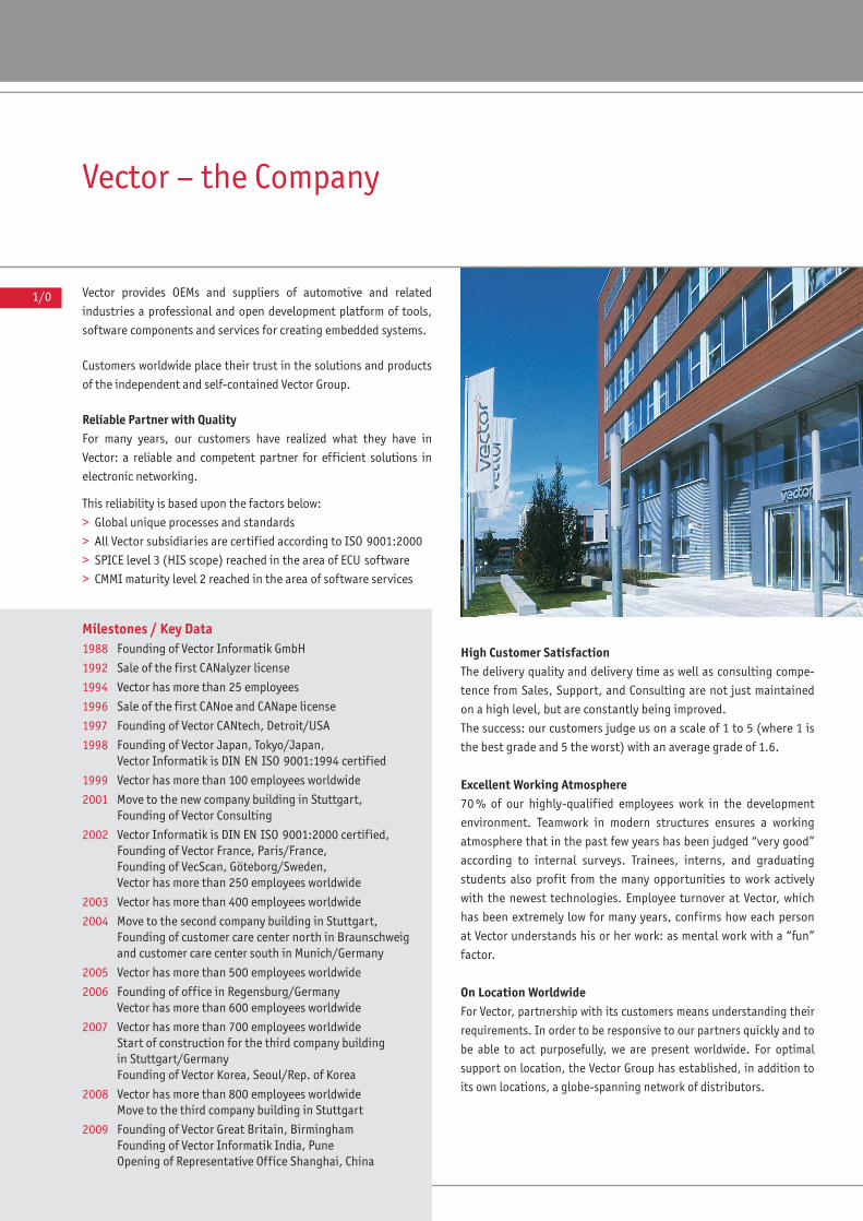
Vector provides OEMs and suppliers of automotive and related
industries a professional and open development platform of tools,
software components and services for creating embedded systems.
Customers worldwide place their trust in the solutions and products
of the independent and self-contained Vector Group.
Reliable Partner with QualityFor many years, our customers have realized what they have in
Vector: a reliable and competent partner for efficient solutions in
electronic networking.
This reliability is based upon the factors below:
> Global unique processes and standards
> All Vector subsidiaries are certified according to ISO 9001:2000
> SPICE level 3 (HIS scope) reached in the area of ECU software
> CMMI maturity level 2 reached in the area of software services
High Customer SatisfactionThe delivery quality and delivery time as well as consulting compe-
tence from Sales, Support, and Consulting are not just maintained
on a high level, but are constantly being improved.
The success: our customers judge us on a scale of 1 to 5 (where 1 is
the best grade and 5 the worst) with an average grade of 1.6.
Excellent Working Atmosphere70 % of our highly-qualified employees work in the development
environment. Teamwork in modern structures ensures a working
atmosphere that in the past few years has been judged “very good”
according to internal surveys. Trainees, interns, and graduating
students also profit from the many opportunities to work actively
with the newest technologies. Employee turnover at Vector, which
has been extremely low for many years, confirms how each person
at Vector understands his or her work: as mental work with a “fun”
factor.
On Location WorldwideFor Vector, partnership with its customers means understanding their
requirements. In order to be responsive to our partners quickly and to
be able to act purposefully, we are present worldwide. For optimal
support on location, the Vector Group has established, in addition to
its own locations, a globe-spanning network of distributors.
Milestones / Key Data1988 Founding of Vector Informatik GmbH
1992 Sale of the first CANalyzer license
1994 Vector has more than 25 employees
1996 Sale of the first CANoe and CANape license
1997 Founding of Vector CANtech, Detroit/USA
1998 Founding of Vector Japan, Tokyo/Japan,Vector Informatik is DIN EN ISO 9001:1994 certified
1999 Vector has more than 100 employees worldwide
2001 Move to the new company building in Stuttgart,Founding of Vector Consulting
2002 Vector Informatik is DIN EN ISO 9001:2000 certified,Founding of Vector France, Paris/France,Founding of VecScan, Göteborg/Sweden,Vector has more than 250 employees worldwide
2003 Vector has more than 400 employees worldwide
2004 Move to the second company building in Stuttgart,Founding of customer care center north in Braunschweigand customer care center south in Munich/Germany
2005 Vector has more than 500 employees worldwide
2006 Founding of office in Regensburg/GermanyVector has more than 600 employees worldwide
2007 Vector has more than 700 employees worldwideStart of construction for the third company building in Stuttgart/GermanyFounding of Vector Korea, Seoul/Rep. of Korea
2008 Vector has more than 800 employees worldwideMove to the third company building in Stuttgart
2009 Founding of Vector Great Britain, BirminghamFounding of Vector Informatik India, PuneOpening of Representative Office Shanghai, China
1/1
XXXXXXXXXXXXVECTOR – THE COMPANY
1/1
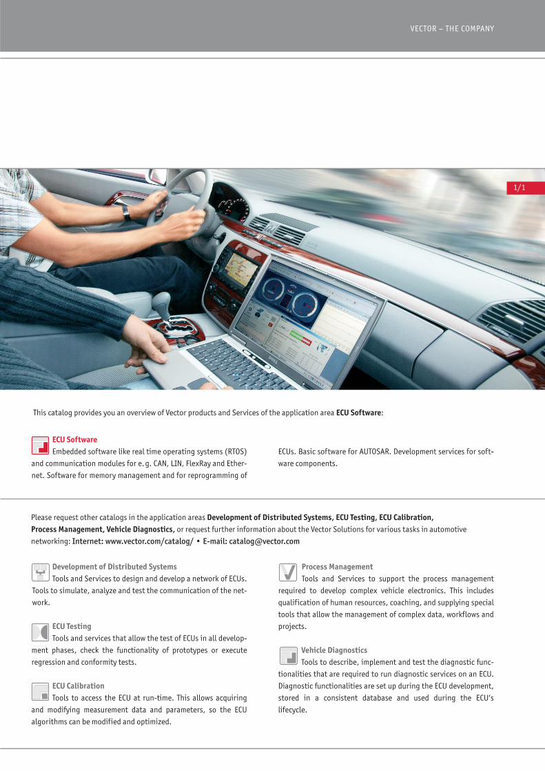
This catalog provides you an overview of Vector products and Services of the application area ECU Software:
Process ManagementTools and Services to support the process management
required to develop complex vehicle electronics. This includes
qualification of human resources, coaching, and supplying special
tools that allow the management of complex data, workflows and
projects.
Vehicle Diagnostics Tools to describe, implement and test the diagnostic func-
tionalities that are required to run diagnostic services on an ECU.
Diagnostic functionalities are set up during the ECU development,
stored in a consistent database and used during the ECU‘s
lifecycle.
Development of Distributed SystemsTools and Services to design and develop a network of ECUs.
Tools to simulate, analyze and test the communication of the net-
work.
ECU TestingTools and services that allow the test of ECUs in all develop-
ment phases, check the functionality of prototypes or execute
regression and conformity tests.
ECU CalibrationTools to access the ECU at run-time. This allows acquiring
and modifying measurement data and parameters, so the ECU
algorithms can be modified and optimized.
Please request other catalogs in the application areas Development of Distributed Systems, ECU Testing, ECU Calibration, Process Management, Vehicle Diagnostics, or request further information about the Vector Solutions for various tasks in automotive
networking: Internet: www.vector.com/catalog/ • E-mail: [email protected]
ECUs. Basic software for AUTOSAR. Development services for soft-
ware components.
ECU SoftwareEmbedded software like real time operating systems (RTOS)
and communication modules for e.g. CAN, LIN, FlexRay and Ether-
net. Software for memory management and for reprogramming of
1/2
Bus Systems, Embedded Network Protocols, Standards and appropriate Vector Products
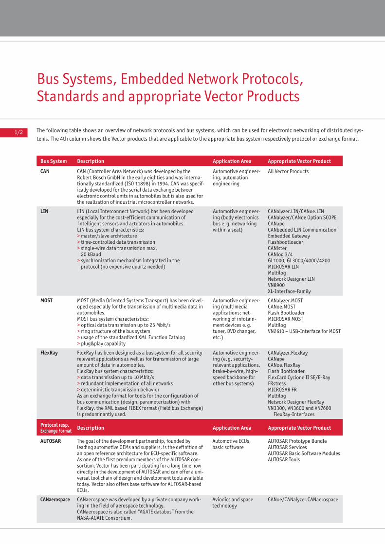
The following table shows an overview of network protocols and bus systems, which can be used for electronic networking of distributed sys-
tems. The 4th column shows the Vector products that are applicable to the appropriate bus system respectively protocol or exchange format.
Bus System Description Application Area Appropriate Vector Product Page
CAN (Controller Area Network) was developed by the Robert Bosch GmbH in the early eighties and was interna-tionally standardized (ISO 11898) in 1994. CAN was specif-ically developed for the serial data exchange betweenelectronic control units in automobiles but is also used forthe realization of industrial microcontroller networks.
LIN (Local Interconnect Network) has been developed especially for the cost-efficient communication ofintelligent sensors and actuators in automobiles.LIN bus system characteristics:> master/slave architecture> time-controlled data transmission> single-wire data transmission max.
20 kBaud> synchronization mechanism integrated in the
protocol (no expensive quartz needed)
MOST (Media Oriented Systems Transport) has been devel-oped especially for the transmission of multimedia data inautomobiles.MOST bus system characteristics:> optical data transmission up to 25 Mbit/s> ring structure of the bus system> usage of the standardized XML Function Catalog> plug&play capability
FlexRay has been designed as a bus system for all security-relevant applications as well as for transmission of largeamount of data in automobiles. FlexRay bus system characteristics:> data transmission up to 10 Mbit/s> redundant implementation of all networks> deterministic transmission behaviorAs an exchange format for tools for the configuration ofbus communication (design, parameterization) with FlexRay, the XML based FIBEX format (Field bus Exchange)is predominantly used.
Automotive engineer-ing, automation engineering
Automotive engineer-ing (body electronicsbus e.g. networkingwithin a seat)
Automotive engineer-ing (multimedia applications; net-working of infotain-ment devices e.g.tuner, DVD changer,etc.)
Automotive engineer-ing (e.g. security-relevant applications,brake-by-wire, high-speed backbone forother bus systems)
All Vector Products
CANalyzer.LIN/CANoe.LINCANalyzer/CANoe Option SCOPECANapeCANbedded LIN CommunicationEmbedded GatewayFlashbootloaderCANisterCANlog 3/4GL1000, GL3000/4000/4200MICROSAR LINMultilogNetwork Designer LINVN8900XL-Interface-Family
CANalyzer.MOSTCANoe.MOSTFlash BootloaderMICROSAR MOSTMultilogVN2610 – USB-Interface for MOST
CANalyzer.FlexRay CANapeCANoe.FlexRay Flash Bootloader FlexCard Cyclone II SE/E-RayFRstressMICROSAR FRMultilogNetwork Designer FlexRay VN3300, VN3600 and VN7600
FlexRay-Interfaces
●●●
3/83/125/2●●●
2/18●●●●
●●
5/22/22●●
●●●
5/2●●
2/16●●
●
CAN
LIN
MOST
FlexRay
The goal of the development partnership, founded by leading automotive OEMs and suppliers, is the definition ofan open reference architecture for ECU-specific software.As one of the first premium members of the AUTOSAR con-sortium, Vector has been participating for a long time nowdirectly in the development of AUTOSAR and can offer a uni-versal tool chain of design and development tools availabletoday. Vector also offers base software for AUTOSAR-basedECUs.
CANaerospace was developed by a private company work-ing in the field of aerospace technology. CANaerospace is also called “AGATE databus” from the NASA-AGATE Consortium.
Automotive ECUs, basic software
Avionics and space technology
AUTOSAR Prototype BundleAUTOSAR ServicesAUTOSAR Basic Software ModulesAUTOSAR Tools
CANoe/CANalyzer.CANaerospace
AUTOSAR
CANaerospace
Protocol resp. Description Application Area Appropriate Vector Product PageExchange Format
2/22/522/62/42
●

1/3
BUS SYSTEMS, EMBEDDED NETWORK PROTOCOLS, STANDARDS AND APPROPRIATE VECTOR PRODUCTS
X/XX = Product information included in this catalog● = Product information included in other application area catalogs or on the internet. Please request further catalogs about the application areas Development of Distributed Systems, ECU Testing, ECU Calibration, Process Management or Vehicle Diagnostics at:Internet: www.vector.com/catalog/ • E-mail: [email protected]
J1939 is a communication protocol based on CAN for real-time data exchange between electronic control units(ECUs) in the area of commercial vehicles. It describes the information exchanged between the ECUsin such a system. ISO11783 is a further development foragricultural engineering.
NMEA 2000® is a communication protocol based on J1939from the National Marine Electronics Association (NMEA)for the realtime data exchange between electronic controlunits in maritime electronics.
SAE J1708 defines a serial, bidirectional network for use inthe commercial vehicle industry. The SAE J1587 Standardregulates communication and standardized data exchangebetween different ECU based on SAE J1708 networks.
The CANopen profile family specifies standardized commu-nication mechanisms and device functionalities.CANopen is maintained by “CAN in Automation” (CiA), andcan be implemented free of license.
The SAE J2534 standard defines the re-programming ofECUs via a PassThru interface. The purpose of this standardis to provide a unified communication capability via astandardized PC interface basically intended for flashingbut also for diagnostics and other purposes.
Ethernet-based networks and the protocols built uponthem are used in IT networks for decades. In the meantimethey continue to grow in importance in the embeddedenvironment. The main focus is on transmission of periodicsignals and real-time capability.
XCP is an improved and generalized version of the CAN Cali-bration Protocol V2.1. (CCP). XCP can be used also in non-CAN networks (e.g. FlexRay, SPI, SCI). The main benefit ofXCP is the independence concerning the transport layer.
Keyword Protocol 2000 (KWP2000; ISO 14230) and “UnifiedDiagnostic Services” (UDS; ISO 14229) are standardized diagnostic protocols for electronic control units. The physical access to the ECU is possible via a serial con-nection (“K-line” KWP-on-K-Line) or via CAN (KWP-on-CAN,UDS-on-CAN).
The ODX format (Open Diagnostic Data Exchange) is basedon the ASAM-MCD-2D-Basic working draft. Manufacturersof vehicles, electronic control units, and testers can writeand exchange electronic control unit data in the uniformODX format, which covers all manufacturers.
The RP1210 specification defines an open interface (API)between Windows-based applications and in-vehicle com-munication networks. This interface offers functionalityfor bus systems – such as CAN and J1708 – as well as for higher layer protocols such as J1939 and J1587.
Commercial vehicle engineering, railway engineering, agricultural engineering
Marine engineering
Commercial vehicles engineering
Automation engineering,CAN embedded
Vehicle ECUs, Diagnostics, PassThrure-programming
Car2x, vehicles engi-neering, automationengineering, factoryautomation
Automotive engineer-ing, development ofelectronic controlunits, measurementand calibration
Diagnostics of vehicleelectronic controlunits, measurementand calibration
Diagnostics of vehicleelectronic controlunits
Commercial vehiclesengineering, enginecontrol
CANoe.J1939CANalyzer.J1939CANoe.ISO11783CANbedded J1939CANape
CANoe.NMEA2000CANalyzer.NMEA2000CANbedded J1939
CANoe/CANalyzer.J1587
CANoe.CANopenCANalyzer.CANopenCANerator CANopenProCANopenCANedsCANopen Master Source CodeCANopen Slave Source Code
PassThru XL Library
CANoe.IPCANalyzer.IPMICROSAR IP
CANapeXCP software componentCANoe Option XCPGL1000, GL3000/4000/4200
CANapeCANdelaStudioCANdescCANoeCANditoCANoe.DiVaCANditoFlashIndigo
CANdelaStudioCANdelaFlashCANditoCANapeCANoeCANditoFlashIndigoCANoe.DiVa
RP1210 API
●●●
3/6●
●●
3/6
●
●●
3/28●●
3/223/26
●
●●
2/20
●3/30●●
●●
3/14●●●
5/12●
●5/10●●●
5/12●●
●
◆
J1939/ISO11783
NMEA 2000
J1587/J1708
CANopen
J2534
Ethernet/IP
XCP/CCP
KWP2000/UDS
ODX
RP1210
Protocol resp. Description Application Area Appropriate Vector Product PageExchange Format
1/4
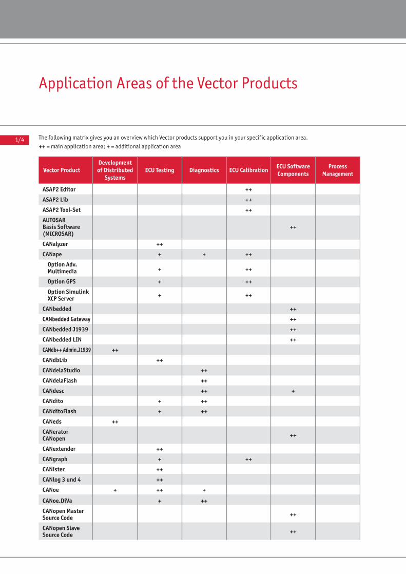
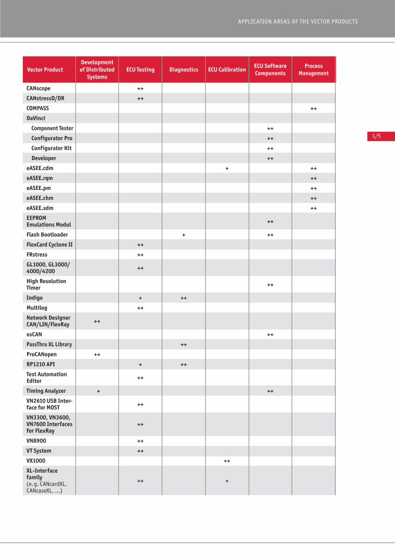
Application Areas of the Vector Products
The following matrix gives you an overview which Vector products support you in your specific application area.
++ = main application area; + = additional application area
ASAP2 Editor ++ ●
ASAP2 Lib ++ ●
ASAP2 Tool-Set ++ ●
AUTOSAR Basis Software ++ 2/2(MICROSAR)
CANalyzer ++ ●
CANape + + ++ ●
Option Adv.+ ++ ●Multimedia
Option GPS + ++ ●
Option Simulink + ++ ●XCP Server
CANbedded ++ 3/2
CANbedded Gateway ++ 3/12
CANbedded J1939 ++ 3/6
CANbedded LIN ++ 3/8
CANdb++ Admin.J1939 ++ ●
CANdbLib ++ ●
CANdelaStudio ++ ●
CANdelaFlash ++ 5/10
CANdesc ++ + 3/14
CANdito + ++ ●
CANditoFlash + ++ 5/12
CANeds ++ ●
CANerator CANopen ++ 3/28
CANextender ++ ●
CANgraph + ++ ●
CANister ++ ●
CANlog 3 und 4 ++ ●
CANoe + ++ + ●
CANoe.DiVa + ++ ●
CANopen Master Source Code ++ 3/22
CANopen Slave Source Code ++ 3/26
Vector ProductDevelopment of Distributed
SystemsECU Testing Diagnostics ECU Calibration ECU Software
ComponentsProcess
Management Page
APPLICATION AREAS OF THE VECTOR PRODUCTS
1/5
X/XX = Product information included in this catalog● = Product information included in other application area catalogs or on the internet. Please request further catalogs about the application areas Development of Distributed Systems, ECU Testing, ECU Calibration, Process Management or Vehicle Diagnostics at:Internet: www.vector.com/catalog/ • E-mail: [email protected]
Steuergeräte-Kalibrierung
Steuergeräte-Software-
Komponenten
Prozess-management Seite
CANscope ++ ●
CANstressD/DR ++ ●
COMPASS ++ ●
DaVinci
Component Tester ++ 2/44
Configurator Pro ++ 2/48
Configurator Kit ++ 2/50
Developer ++ 2/42
eASEE.cdm + ++ ●
eASEE.rqm ++ ●
eASEE.pm ++ ●
eASEE.chm ++ ●
eASEE.sdm ++ ●
EEPROM Emulations Modul ++ 5/6
Flash Bootloader + ++ 5/2
FlexCard Cyclone II ++ ●
FRstress ++ ●
GL1000, GL3000/4000/4200 ++ ●
High Resolution Timer ++ 4/4
Indigo + ++ ●
Multilog ++ ●
Network Designer ++ ●CAN/LIN/FlexRay
osCAN ++ 4/2
PassThru XL Library ++ ●
ProCANopen ++ ●
RP1210 API + ++ ●
Test AutomationEditor ++ ●
Timing Analyzer + ++ 4/6
VN2610 USB Inter- ++ ●face for MOST
VN3300, VN3600,VN7600 Interfaces ++ ●for FlexRay
VN8900 ++ ●
VT System ++ ●
VX1000 ++ ●
XL-Interface family(e.g. CANcardXL, ++ + ●CANcaseXL, …)
Vector ProductDevelopment of Distributed
SystemsECU Testing Diagnostics ECU Calibration ECU Software
ComponentsProcess
Management Page
1/6
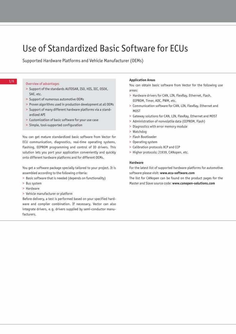
Use of Standardized Basic Software for ECUsSupported Hardware Platforms and Vehicle Manufacturer (OEMs)
You can get mature standardized basic software from Vector for
ECU communication, diagnostics, real-time operating systems,
flashing, EEPROM programming and control of IO drivers. This
solution lets you port your application conveniently and quickly
onto different hardware platforms and for different OEMs.
You get a software package specially tailored to your project. It is
assembled according to the following criteria:
> Basic software that is needed (depends on functionality)
> Bus system
> Hardware
> Vehicle manufacturer or platform
Before delivery, a test is performed based on your specified hard-
ware and compiler combination. If necessary, Vector can also
integrate drivers, e.g. drivers supplied by semi-conductor manu-
facturers.
Application AreasYou can obtain basic software from Vector for the following use
areas:
> Hardware drivers for CAN, LIN, FlexRay, Ethernet, Flash,
EEPROM, Timer, ADC, PWM, etc.
> Communication software for CAN, LIN, FlexRay, Ethernet and
MOST
> Gateway solutions for CAN, LIN, FlexRay, Ethernet and MOST
> Administration of nonvolatile data (EEPROM, Flash)
> Diagnostics with error memory module
> Watchdog
> Flash Bootloader
> Operating system
> Calibration protocols XCP and CCP
> Higher protocols: J1939, CANopen, etc.
HardwareFor the latest list of supported hardware platforms for automotive
software please visit: www.ecu-software.comThe list for CANopen can be found on the product pages for the
Master and Slave source code: www.canopen-solutions.com
Overview of advantages
> Support of the standards AUTOSAR, ISO, HIS, IEC, OSEK,
SAE, etc.
> Support of numerous automotive OEMs
> Proven algorithms used in production development at all OEMs
> Support of many different hardware platforms via a stand-
ardized API
> Customization of basic software for your use case
> Simple, tool-supported configuration
1/7
ECU SOFTWARE
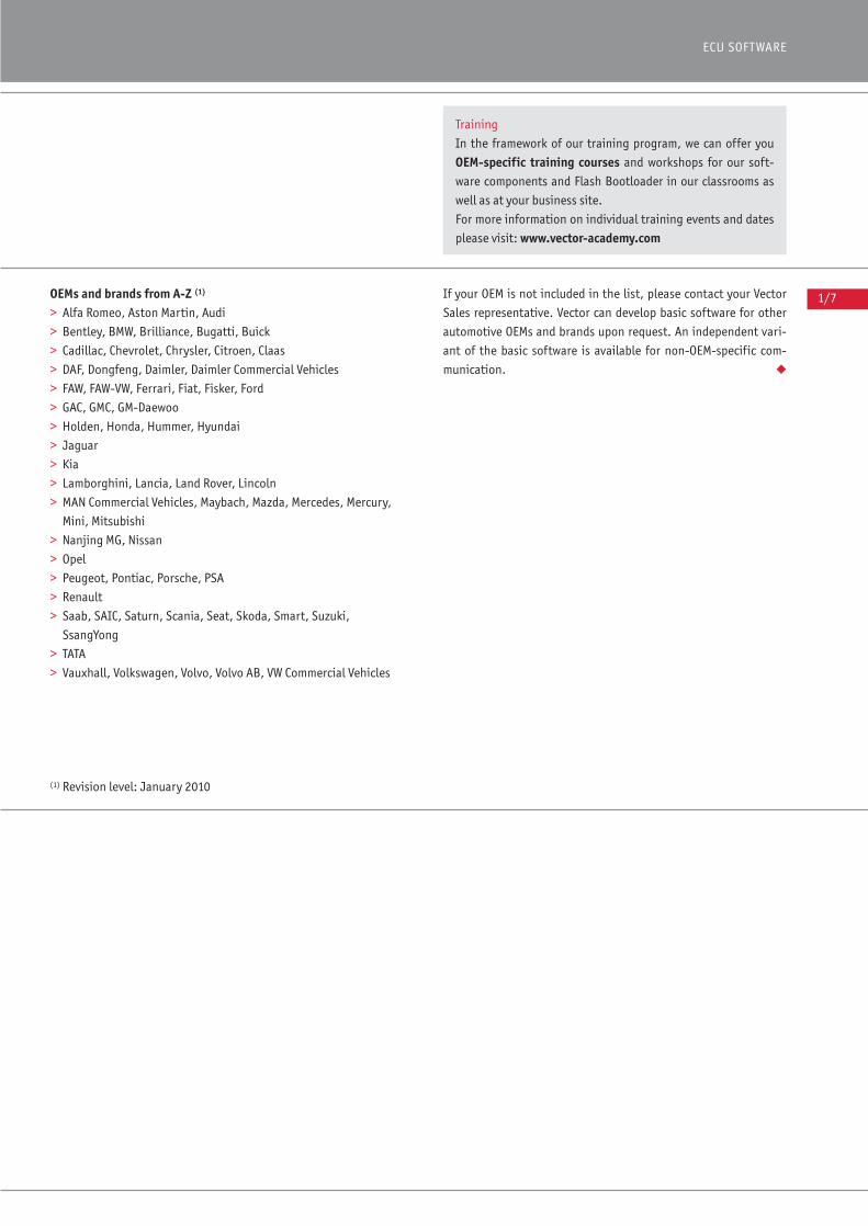
OEMs and brands from A-Z (1)
> Alfa Romeo, Aston Martin, Audi
> Bentley, BMW, Brilliance, Bugatti, Buick
> Cadillac, Chevrolet, Chrysler, Citroen, Claas
> DAF, Dongfeng, Daimler, Daimler Commercial Vehicles
> FAW, FAW-VW, Ferrari, Fiat, Fisker, Ford
> GAC, GMC, GM-Daewoo
> Holden, Honda, Hummer, Hyundai
> Jaguar
> Kia
> Lamborghini, Lancia, Land Rover, Lincoln
> MAN Commercial Vehicles, Maybach, Mazda, Mercedes, Mercury,
Mini, Mitsubishi
> Nanjing MG, Nissan
> Opel
> Peugeot, Pontiac, Porsche, PSA
> Renault
> Saab, SAIC, Saturn, Scania, Seat, Skoda, Smart, Suzuki,
SsangYong
> TATA
> Vauxhall, Volkswagen, Volvo, Volvo AB, VW Commercial Vehicles
(1) Revision level: January 2010
If your OEM is not included in the list, please contact your Vector
Sales representative. Vector can develop basic software for other
automotive OEMs and brands upon request. An independent vari-
ant of the basic software is available for non-OEM-specific com-
munication. ◆
Training
In the framework of our training program, we can offer you
OEM-specific training courses and workshops for our soft-
ware components and Flash Bootloader in our classrooms as
well as at your business site.
For more information on individual training events and dates
please visit: www.vector-academy.com
1/8
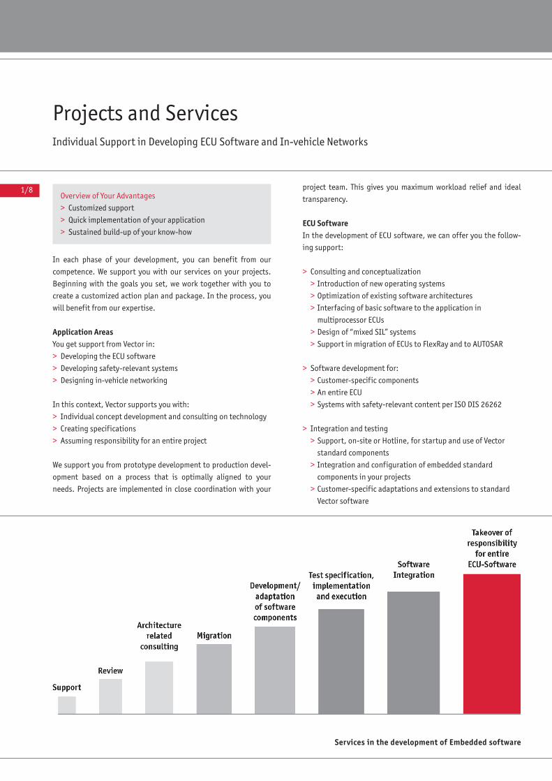
Projects and ServicesIndividual Support in Developing ECU Software and In-vehicle Networks
In each phase of your development, you can benefit from our
competence. We support you with our services on your projects.
Beginning with the goals you set, we work together with you to
create a customized action plan and package. In the process, you
will benefit from our expertise.
Application AreasYou get support from Vector in:
> Developing the ECU software
> Developing safety-relevant systems
> Designing in-vehicle networking
In this context, Vector supports you with:
> Individual concept development and consulting on technology
> Creating specifications
> Assuming responsibility for an entire project
We support you from prototype development to production devel-
opment based on a process that is optimally aligned to your
needs. Projects are implemented in close coordination with your
project team. This gives you maximum workload relief and ideal
transparency.
ECU SoftwareIn the development of ECU software, we can offer you the follow-
ing support:
> Consulting and conceptualization
> Introduction of new operating systems
> Optimization of existing software architectures
> Interfacing of basic software to the application in
multiprocessor ECUs
> Design of “mixed SIL” systems
> Support in migration of ECUs to FlexRay and to AUTOSAR
> Software development for:
> Customer-specific components
> An entire ECU
> Systems with safety-relevant content per ISO DIS 26262
> Integration and testing
> Support, on-site or Hotline, for startup and use of Vector
standard components
> Integration and configuration of embedded standard
components in your projects
> Customer-specific adaptations and extensions to standard
Vector software
Services in the development of Embedded software
Overview of Your Advantages
> Customized support
> Quick implementation of your application
> Sustained build-up of your know-how
1/9
ECU SOFTWARE
> OEM or Tier-1 specific integration reviews for standard Vector
components
Model-based software development can also be performed.
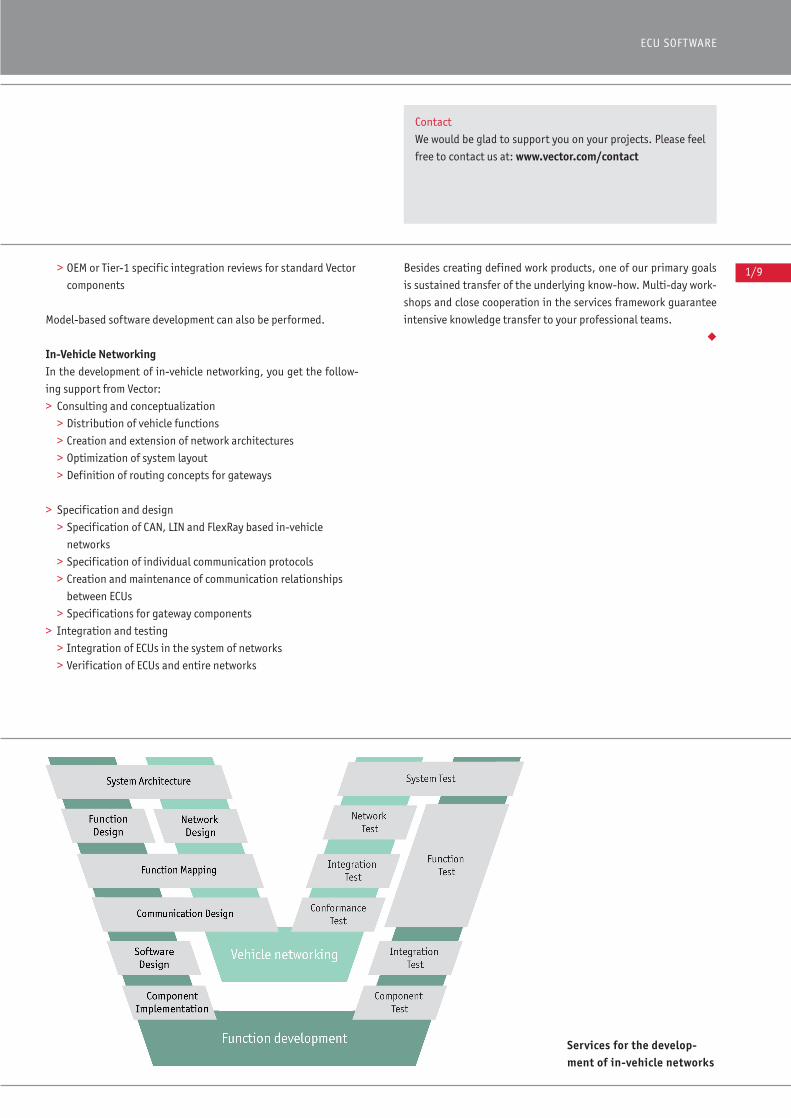
In-Vehicle NetworkingIn the development of in-vehicle networking, you get the follow-
ing support from Vector:
> Consulting and conceptualization
> Distribution of vehicle functions
> Creation and extension of network architectures
> Optimization of system layout
> Definition of routing concepts for gateways
> Specification and design
> Specification of CAN, LIN and FlexRay based in-vehicle
networks
> Specification of individual communication protocols
> Creation and maintenance of communication relationships
between ECUs
> Specifications for gateway components
> Integration and testing
> Integration of ECUs in the system of networks
> Verification of ECUs and entire networks
Besides creating defined work products, one of our primary goals
is sustained transfer of the underlying know-how. Multi-day work-
shops and close cooperation in the services framework guarantee
intensive knowledge transfer to your professional teams.
◆
Services for the develop-ment of in-vehicle networks
Contact
We would be glad to support you on your projects. Please feel
free to contact us at: www.vector.com/contact
1/10
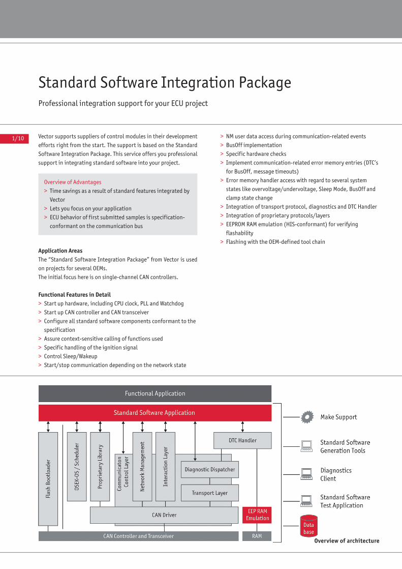
Standard Software Integration PackageProfessional integration support for your ECU project
Vector supports suppliers of control modules in their development
efforts right from the start. The support is based on the Standard
Software Integration Package. This service offers you professional
support in integrating standard software into your project.
Application AreasThe “Standard Software Integration Package” from Vector is used
on projects for several OEMs.
The initial focus here is on single-channel CAN controllers.
Functional Features in Detail> Start up hardware, including CPU clock, PLL and Watchdog
> Start up CAN controller and CAN transceiver
> Configure all standard software components conformant to the
specification
> Assure context-sensitive calling of functions used
> Specific handling of the ignition signal
> Control Sleep/Wakeup
> Start/stop communication depending on the network state
> NM user data access during communication-related events
> BusOff implementation
> Specific hardware checks
> Implement communication-related error memory entries (DTC’s
for BusOff, message timeouts)
> Error memory handler access with regard to several system
states like overvoltage/undervoltage, Sleep Mode, BusOff and
clamp state change
> Integration of transport protocol, diagnostics and DTC Handler
> Integration of proprietary protocols/layers
> EEPROM RAM emulation (HIS-conformant) for verifying
flashability
> Flashing with the OEM-defined tool chain
Overview of architecture
Overview of Advantages
> Time savings as a result of standard features integrated by
Vector
> Lets you focus on your application
> ECU behavior of first submitted samples is specification-
conformant on the communication bus

1/11
ECU SOFTWARE
Other Integration Properties> Integration of standard software according to questionnaire
> Two updates of database over course of project
> Database adaptation for missing attributes, additional CAN
identifiers and any other necessary entries
> Adaptation of proprietary configuration files for a consistent
configuration
> Test and release with commercially available tools
Scope of Delivery> Delivery of integrated standard software in complete project
tree, with make support and runtime environment
> Documentation
> Test report
> Local startup
> Hotline/support
ExtensionsBeyond the normal scope (single-channel CAN controllers), Vector
offers you to integrate additional buses such as LIN, MOST and
FlexRay, multi-channel ECU’s, as well as project-specific software.
◆
Further Information
You can obtain further information about the “Standard Soft-
ware Integration Package” by
E-mail: [email protected]
or by telephone: +49 (0)941 20865-210
Acronyms
DTC – Diagnostic Trouble Code
NM – Network Management
HIS – Hersteller Initiative Software
Special Functions
We would be glad to handle development and integration
tasks for other contents of your project, such as:
> Project-specific components or
> A functional ECU application.
2/0
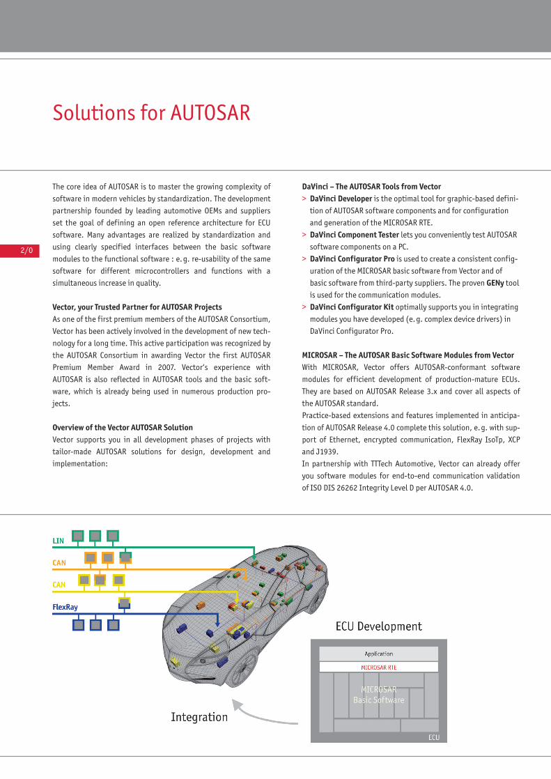
Solutions for AUTOSAR
The core idea of AUTOSAR is to master the growing complexity of
software in modern vehicles by standardization. The development
partnership founded by leading automotive OEMs and suppliers
set the goal of defining an open reference architecture for ECU
software. Many advantages are realized by standardization and
using clearly specified interfaces between the basic software
modules to the functional software : e.g. re-usability of the same
software for different microcontrollers and functions with a
simultaneous increase in quality.
Vector, your Trusted Partner for AUTOSAR ProjectsAs one of the first premium members of the AUTOSAR Consortium,
Vector has been actively involved in the development of new tech-
nology for a long time. This active participation was recognized by
the AUTOSAR Consortium in awarding Vector the first AUTOSAR
Premium Member Award in 2007. Vector‘s experience with
AUTOSAR is also reflected in AUTOSAR tools and the basic soft-
ware, which is already being used in numerous production pro-
jects.
Overview of the Vector AUTOSAR SolutionVector supports you in all development phases of projects with
tailor-made AUTOSAR solutions for design, development and
implementation:
DaVinci – The AUTOSAR Tools from Vector> DaVinci Developer is the optimal tool for graphic-based defini-
tion of AUTOSAR software components and for configuration
and generation of the MICROSAR RTE.
> DaVinci Component Tester lets you conveniently test AUTOSAR
software components on a PC.
> DaVinci Configurator Pro is used to create a consistent config-
uration of the MICROSAR basic software from Vector and of
basic software from third-party suppliers. The proven GENy tool
is used for the communication modules.
> DaVinci Configurator Kit optimally supports you in integrating
modules you have developed (e.g. complex device drivers) in
DaVinci Configurator Pro.
MICROSAR – The AUTOSAR Basic Software Modules from VectorWith MICROSAR, Vector offers AUTOSAR-conformant software
modules for efficient development of production-mature ECUs.
They are based on AUTOSAR Release 3.x and cover all aspects of
the AUTOSAR standard.
Practice-based extensions and features implemented in anticipa-
tion of AUTOSAR Release 4.0 complete this solution, e.g. with sup-
port of Ethernet, encrypted communication, FlexRay IsoTp, XCP
and J1939.
In partnership with TTTech Automotive, Vector can already offer
you software modules for end-to-end communication validation
of ISO DIS 26262 Integrity Level D per AUTOSAR 4.0.
2/1
AUTOSAR
Further Tools Take advantage of the comprehensive Vector tool chain to develop
your AUTOSAR ECUs and systems.
> The eASEE Automotive Solution lets you specify and manage
in-vehicle electronic systems. This ranges from defining
requirements to designing distributed functions and defining
components such as sensors, actuators and ECUs. Data commu-
nication in the networks can also be defined with eASEE.
> Network Designer is used to design a vehicle’s networking
architecture and data communication for the networks.
> CANdela Studio let’s you specify the diagnostic functionality of
your ECUs.
Vector can offer you a complete solution for your projects together
with numerous other tools for ECU testing as well as measurement
and calibration.
The Easy Way to Get Started with AUTOSAR Besides training courses on fundamentals and on specific pro-
ducts, Vector also offers on-site support in project implementa-
tion and in introducing the AUTOSAR software.
The AUTOSAR Prototype Bundle from Vector gives you a solution
for prototype development of AUTOSAR systems. It offers a struc-
tured approach for training in the AUTOSAR methodology and
gives you an opportunity to evaluate the functionality and per-
formance of the AUTOSAR software.
Support for Your ProjectsVector accompanies you from the early evaluation phase to pro-
duction projects. Together with you, we can develop a comprehen-
sive solution for your ECU. In the process, it does not matter
whether you are using Vector products, your own in-house devel-
opments or third-party components. We support your projects
with experience and integration know-how.
>> CONTENTS
AUTOSAR Prototype Bundle 2/2MICROSAR 2/6MICROSAR OS 2/10MICROSAR COM 2/12MICROSAR CAN 2/14MICROSAR FR 2/16MICROSAR LIN 2/18MICROSAR IP 2/20MICROSAR MOST 2/22MICROSAR MEM 2/24MICROSAR SYS 2/26MICROSAR DIAG 2/28MICROSAR CAL 2/32MICROSAR EXT 2/34
MICROSAR IO 2/36MICROSAR RTE 2/38Identity Manager for AUTOSAR 2/40DaVinci Developer 2/42DaVinci Component Tester 2/44DaVinci Configurator Pro 2/48DaVinci Configurator Kit 2/50AUTOSAR Services 2/52
When choosing the AUTOSAR solution from Vector:
> You benefit from a seamless tool chain: From the design of
your system to the development of your functional soft-
ware and integration of the software in your ECU.
> With MICROSAR you get a complete set of basic software
from a single source, which you can use individually or in
conjunction with third-party components.
> Vector, together with its partner TTTech Automotive, offers
you a reliable solution for safety-relevant ECUs per ISO DIS
26262.
> You do not need to migrate to AUTOSAR all at once. Vector
can show you solutions for stepwise migration without loss
of quality.
> You are choosing a future-oriented solution with a reliable
partner.
Vector Katalog ECU Software EN 11.05.2010 11:32 Uhr Seite 2/1
2/2
AUTOSAR Prototype BundleThe complete bundle for developing prototype ECUs conforming to the AUTOSAR standard
The AUTOSAR Prototype Bundle is a comprehensive package of
AUTOSAR basic software and design and configuration tools from
Vector. This package lets you develop entire ECUs with an
AUTOSAR-conformant software architecture. You get an in-depth
look into the AUTOSAR world – from the design and configuration
process to implementation of the actual basic software.
Application AreasThe AUTOSAR Prototype Bundle supports both the automotive
OEM – in evaluating AUTOSAR processes and methods – and sup-
pliers in creating their first AUTOSAR-conformant prototype ECUs.
Since the tools and basic software are at a level of production
maturity, you can reliably use the Vector solution to evaluate
AUTOSAR with regard to:
> Efficiency of the basic software
> Integration of the tools in your development environment
> Potential uses of AUTOSAR concepts in your application area
The AUTOSAR Prototype Bundle also provides an optimal founda-
tion for initial developments of AUTOSAR-conformant software
components for service providers who focus on the application
level.
If your focus is on evaluation of the AUTOSAR method and tools,
you can obtain the AUTOSAR Prototype Bundle with MICROSAR
CANoe Emulation as well. In this case, you would use the PC with
the CANoe test and development tool from Vector as the runtime
platform and can work without startup of real hardware. Nonethe-
less, you work with the same methods, tools and basic software as
in the development of a real ECU.
FunctionsThe AUTOSAR Prototype Bundle contains all of the tools needed to
configure and generate the MICROSAR basic software:
The DaVinci Developer tool gives you an easy way to generate
AUTOSAR-conformant ECU applications. Using the graphic editor,
you can describe your AUTOSAR software components quickly and
clearly and define their interfaces. The software components serve
as a basis for the RTE configuration process, which you also
perform with DaVinci Developer.
The DaVinci Configurator Pro tool is used to configure the basic
software modules. You can use the convenient and intuitive user
interface to adapt parameter values for your ECU project. The
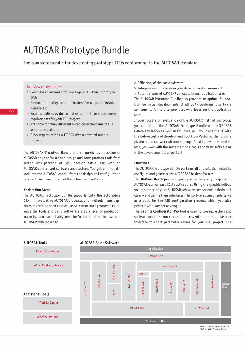
Additional Tools
AUTOSAR Tools AUTOSAR Basic Software
Overview of advantages
> Complete environment for developing AUTOSAR prototype
ECUs
> Production-quality tools and basic software per AUTOSAR
Release 3.x
> Enables realistic evaluation of execution time and memory
requirements for your ECU project
> Available for many different micro-controllers and the PC
as runtime platform
> Quick way to train in AUTOSAR with a detailed sample
project
2/3
AUTOSAR
GENy tool offers special support in configuring the communica-
tion basic software.
All tools perform consistency checks, making it easier for you to
design complex AUTOSAR applications.
Also included are tools used to generate input data for DaVinci
Developer and DaVinci Configurator Pro: You can create network
communication descriptions for CAN, LIN or FlexRay networks
with Network Designer. It supports you with functions for defin-
ing signals, distributing signals to messages and importing/
exporting network data via standard formats.
The CANdelaStudio tool is used to define diagnostic data for your
networks and ECUs. You can export this data via standard
formats, and use the data in automatic configuration of the
MICROSAR diagnostic basic software.
The included MICROSAR basic software modules efficiently and
flexibly implement all basic functions and numerous other func-
tions of AUTOSAR Release 3.x. The modules are bundled in func-
tionally interrelated MICROSAR products:
MICROSAR RTE
> Contains the AUTOSAR RTE (Runtime Environment)
MICROSAR OS
Contains the AUTOSAR basic software module Operating System (OS)
> Implementation of “Scalability Class” SC1 (SC2-SC4 available as
option if supported by processor)
> Fully compatible with OSEK OS
> Supports Schedule Tables
MICROSAR SYS
Contains the AUTOSAR basic software modules
> Communication Manager (COMM)
> Cyclic Redundancy Check Routines (CRC)
> ECU Manager (ECUM)
> Development Error Tracer (DET)
> Watchdog Manager (WDGM)
> Watchdog Interface (WDGIF)
> Scheduler Module (SCHM)
MICROSAR DIAG
Contains the AUTOSAR basic software modules
> Diagnostic Event Manager (DEM)
> Diagnostic Communication Manager (DCM)
> Function Inhibition Manager (FIM)
MICROSAR MEM
Contains the AUTOSAR basic software modules
> NVRAM Manager (NVM)
> Memory Abstraction Interface (MEMIF)
> EEPROM Abstraction (EA)
> Flash EEPROM Emulation (FEE)
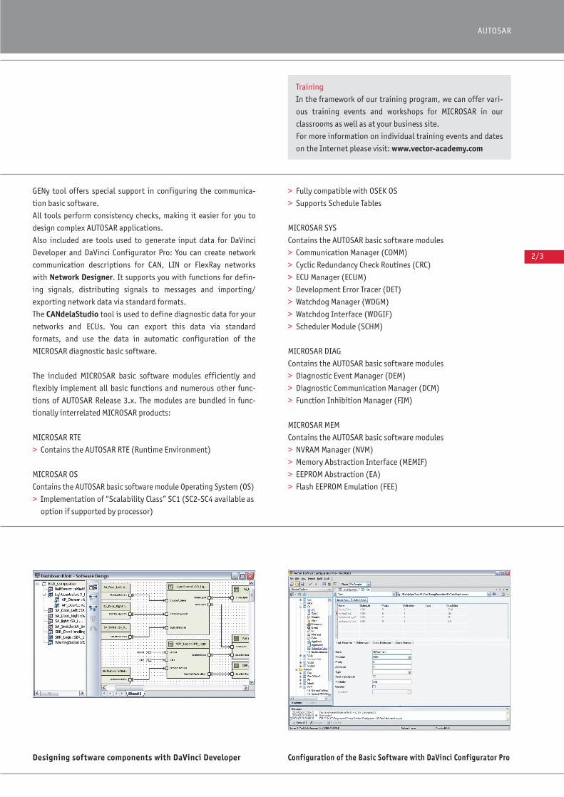
Designing software components with DaVinci Developer Configuration of the Basic Software with DaVinci Configurator Pro
Training
In the framework of our training program, we can offer vari-
ous training events and workshops for MICROSAR in our
classrooms as well as at your business site.
For more information on individual training events and dates
on the Internet please visit: www.vector-academy.com

2/4
MICROSAR CAN
Contains the AUTOSAR basic software modules
> CAN Interface (CANIF)
> CAN Transport Protocol (CANTP)
> CAN Network Management (CANNM)
> CAN State Manager (CANSM)
MICROSAR J1939TP (available as option)
Contains the transport protocols
> BAM – Broadcast Announce Message
> CMDT – Connection Mode Data Transfer
MICROSAR FR
Contains the AUTOSAR basic software modules
> FlexRay Interface (FRIF)
> FlexRay Transport Protocol (FRTP)
> FlexRay Network Management (FRNM)
> FlexRay State Manager (FRSM)
MICROSAR LIN
Contains the AUTOSAR basic software modules
> LIN Interface (LINIF)
> LIN Transport Protocol (LINTP, contained in LINIF)
> LIN State Manager (LINSM)
MICROSAR COM
Contains the AUTOSAR basic software modules
> Communication (COM)
> Network Management Interface (NM)
> PDU Router (PDUR)
> I-PDU Multiplexer (IPDUM) available as option
MICROSAR IO
Contains the AUTOSAR basic software modules
> IO Hardware Abstraction (IOHW)
MICROSAR CAL
Contains the AUTOSAR basic software modules
> General Purpose Timer Driver (GPTDRV)
> Watchdog Driver (WDGDRV)
> Microcontroller Unit Driver (MCUDRV)
> EEPROM Driver (EEPDRV)
> Flash Driver (FLSDRV)
> CAN Driver (CANDRV)
> LIN Driver (LINDRV)
> FlexRay Driver (FRDRV)
> SPI Driver (SPIDRV)
> Input Capture Unit Driver (ICUDRV)
> Pulse Width Modulation Driver (PWMDRV)
> A/D Conversion Driver (ADCDRV)
> PORT Driver (PORTDRV)
> Digital IO Driver (DIODRV)
Special functions
DaVinci Developer has an import/export interface for
AUTOSAR XML files. This interface lets you exchange design
and configuration data. For example, you might use it to
integrate AUTOSAR software components in an ECU you
have developed in a model-based approach using tools like
MATLAB® Simulink®.
All MICROSAR products conform to:
> “Implementation Conformance Class” ICC3, and
> “Configuration Conformance Class” CCC 2.
2/5
AUTOSAR
MICROSAR EXT
Contains the AUTOSAR basic software modules
> CAN Transceiver Driver (CANTRCV)
> FlexRay Transceiver Driver (FRTRCV)
> LIN Transceiver Driver (LINTRCV)
> Vector can implement other drivers for external components
upon request.
Additional Included Features> Sample application
To simplify getting started with the AUTOSAR Prototype Bundle,
the bundle includes a sample application in source code, and a
detailed guide on its use is enclosed.
> Start-up support
> The AUTOSAR Prototype Bundle includes MICROSAR Coaching.
Vector can offer you comprehensive support in initial start-up
and integration of the AUTOSAR basic software in your applica-
tion. We would be glad to assist you at your business site.
Further Options The AUTOSAR Prototype Bundles CAN, LIN and FlexRay may be
used with one another in any combination.
Available Hardware PlatformsThe AUTOSAR Prototype Bundle is available for the most common-
ly used 16-bit and 32-bit hardware platforms. Due to the hardware
dependency of the MICROSAR CAL modules and the MICROSAR OS,
binding statements cannot be made without specific processor
device numbers. The Vector Sales Team would be glad to provide
this information.
MICROSAR CANoe EmulationAs an alternative, Vector also offers the AUTOSAR Prototype Bun-
dle for CANoe as a PC runtime platform. In this case, emulations of
the MICROSAR CAL modules and the MICROSAR OS are included.
The flash memory of the AUTOSAR ECU is also emulated. The
EEPDRV is not needed in this case, and so it is not provided. ◆
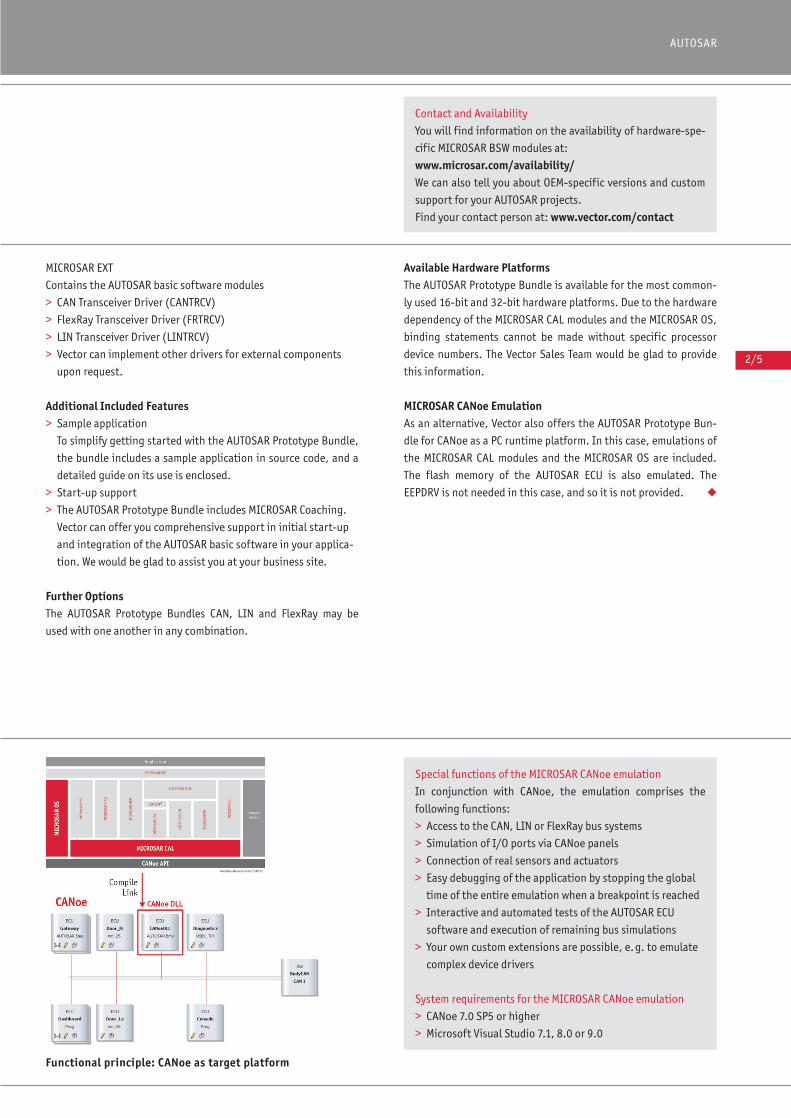
Special functions of the MICROSAR CANoe emulation
In conjunction with CANoe, the emulation comprises the
following functions:
> Access to the CAN, LIN or FlexRay bus systems
> Simulation of I/O ports via CANoe panels
> Connection of real sensors and actuators
> Easy debugging of the application by stopping the global
time of the entire emulation when a breakpoint is reached
> Interactive and automated tests of the AUTOSAR ECU
software and execution of remaining bus simulations
> Your own custom extensions are possible, e.g. to emulate
complex device drivers
System requirements for the MICROSAR CANoe emulation
> CANoe 7.0 SP5 or higher
> Microsoft Visual Studio 7.1, 8.0 or 9.0
Functional principle: CANoe as target platform
Contact and Availability
You will find information on the availability of hardware-spe-
cific MICROSAR BSW modules at:
www.microsar.com/availability/We can also tell you about OEM-specific versions and custom
support for your AUTOSAR projects.
Find your contact person at: www.vector.com/contact
2/6
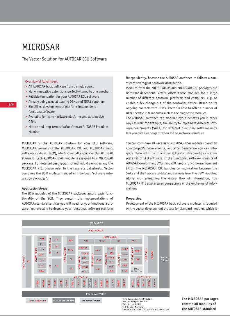
MICROSARThe Vector Solution for AUTOSAR ECU Software
MICROSAR is the AUTOSAR solution for your ECU software.
MICROSAR consists of the MICROSAR RTE and MICROSAR basic
software modules (BSW), which cover all aspects of the AUTOSAR
standard. Each AUTOSAR BSW module is assigned to a MICROSAR
package. For detailed descriptions of individual packages and the
MICROSAR RTE, please refer to the separate datasheets. Vector
combines the BSW modules needed in individual “software inte-
gration packages”.
Application AreasThe BSW modules of the MICROSAR packages assure basic func-
tionality of the ECU. They contain the implementations of
AUTOSAR standard services you will need for your functional soft-
ware. You are able to develop your functional software platform
independently, because the AUTOSAR architecture follows a con-
sistent strategy of hardware abstraction.
Modules from the MICROSAR OS and MICROSAR CAL packages are
hardware-dependent. Vector offers these modules for a large
number of different hardware platforms and compilers, e.g. to
enable quick change-out of the controller device. Based on its
ongoing contacts with OEMs, Vector is able to offer a number of
OEM-specific BSW modules such as the diagnostic modules.
The AUTOSAR architecture’s modular layout benefits you in other
ways as well; for example, the ability to implement different soft-
ware components (SWCs) for different functional software units
lets you give clear organization to the software structure.
You can configure all necessary MICROSAR BSW modules based on
your project’s requirements, and after generation you can inte-
grate them with the functional software. This produces a com-
plete set of ECU software. If the functional software consists of
AUTOSAR-conformant SWCs, you will need a run-time environment
(RTE). The MICROSAR RTE handles communication between the
SWCs and their access to data and services from the BSW modules.
Along with managing the entire flow of information, the
MICROSAR RTE also assures consistency in the exchange of infor-
mation.
PropertiesDevelopment of the MICROSAR basic software modules is founded
on the Vector development process for standard modules, which is
The MICROSAR packagescontain all modules ofthe AUTOSAR standard
Overview of Advantages
> All AUTOSAR basic software from a single source
> Many innovative extensions perfectly tuned to one another
> Reliable foundation for your AUTOSAR ECU software
> Already being used at leading OEMs and TIER1 suppliers
> Simplifies development of platform-independent
functionalsoftware
> Available for many hardware platforms and automotive
OEMs
> Mature and long-term solution from an AUTOSAR Premium
Member
2/7
AUTOSAR
based on SPICE Level 3. All MICROSAR packages offer the follow-
ing features:
> Efficient memory utilization and short execution times
> Available for production use
> Conformant to AUTOSAR Release 3.x
> Assistants and timely checks support you in achieving
consistent configuration of your basic software
> Scalable, adaptable to your specific application
> Optimally integrated into your development process
> User-selectable configuration point (pre-compile, link-time
or post-build)
> Communication stack is versatile in its use
> Supports multiple ECUs
> Optional delivery as source code
Production UseThe MICROSAR BSW modules are already being used in production
projects. MICROSAR lets you benefit from Vector’s many years of
experience in implementing embedded standard software. Before
delivery, all MICROSAR Software modules undergo systematic
integration tests for the specific conditions of your application
(hardware platform, compiler, processor device, OEM, with/with-
out RTE, etc.). Upon request, these tests may be extended to
cover software modules from third-party producers (e.g. MCAL
drivers). In addition, each product includes a sample program.
AUTOSAR Release 3.x and ExtensionsAll MICROSAR basic software modules fundamentally conform to
AUTOSAR Release 3.x. In addition, it is possible to integrate MCAL
drivers of the previous Release 2.1.
Modules from MICROSAR IP, MICROSAR J1939 and XCP already
contain important functionality from Release 4.0. Moreover, the
MICROSAR MOST package lets you connect any AUTOSAR ECU to a
MOST ring. All of these extensions are compatible with the rest of
the MICROSAR basic software modules of Release 3.x.
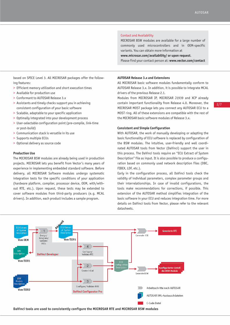
Consistent and Simple ConfigurationWith AUTOSAR, the work of manually developing or adapting the
basic functionality of ECU software is replaced by configuration of
the BSW modules. The intuitive, user-friendly and well coordi-
nated AUTOSAR tools from Vector (DaVinci) support the user in
this process. The DaVinci tools require an “ECU Extract of System
Description” file as input. It is also possible to produce a configu-
ration based on commonly used network description files (DBC,
FIBEX, LDF, etc.).
Early in the configuration process, all DaVinci tools check the
validity of individual parameters, complex parameter groups and
their interrelationships. In case of invalid configurations, the
tools make recommendations for corrections, if possible. This
extension of the AUTOSAR method simplifies integration of the
basic software in your ECU and reduces integration time. For more
details on DaVinci tools from Vector, please refer to the relevant
datasheets.
DaVinci tools are used to consistently configure the MICROSAR RTE and MICROSAR BSW modules
Contact and Availability
MICROSAR BSW modules are available for a large number of
commonly used microcontrollers and in OEM-specific
variants. You can obtain more information at
www.microsar.com/availability/ or upon request.
Please find your contact person at: www.vector.com/contact
2/8
> You can configure the MICROSAR BSW modules with DaVinci
Configurator Pro. Vector recommends the proven GENy configu-
ration tool for configuring the communication-related
MICROSAR modules. GENy is supplied with DaVinci Configurator
Pro. GENy enables cross-module configuration of specific param-
eters and parameter groups. This saves you time compared to
step-wise configuration of individual BSW modules; it also
ensures a compatible configuration of interdependent modules.
> The MICROSAR RTE is configured with DaVinci Developer, the
design tool for SWCs.
ScalabilityIn addition to fulfilling AUTOSAR requirements, the MICROSAR
BSW modules also provide a number of functional extensions. The
extended configuration options let you deactivate unnecessary
functions to optimize the MICROSAR code for your application.
This scalability makes the MICROSAR modules the optimal solution
for both small and challenging applications. MICROSAR is already
being implemented in a wide range of ECUs, such as steering
angle sensors, door ECUs, engine ECUs, central gateways, etc.
MICROSAR may also be used with other operating systems such as
Linux or QNX.
Flexible Development ProcessWith the DaVinci tools it is possible to execute a top-down config-
uration or a bottom-up configuration to integrate the MICROSAR
products in your development process. A combination of the two
approaches offers optimal results. Bottom-up is especially well-
suited to MICROSAR DIAG and MICROSAR IO, while top-down is
ideal for the other MICROSAR BSW modules.
In the bottom-up approach, the configuration of the interfaces of
the functional software is done by using the basic software. This
involves using DaVinci Developer to automatically generate SWC
service ports (including runnables) based on BSW service ports.
This approach gives you quick training in AUTOSAR, and you can
create your first functionally-capable ECU in a short period of time.
In the top-down approach, DaVinci Developer is used to connect
the ports of the SWCs via service mapping to the ports of the BSW
modules – in part automatically. This reduces configuration effort
significantly.
User-Selectable Configuration PointThe configuration point of all MICROSAR basic software modules is
user-selectable. Per AUTOSAR Configuration Conformance Classes
CCC1 to CCC3, you can select the configuration point for each BSW
module; choices are: pre-compile, link-time or post-build.
GENy offers optimal process support for the post-build configured
communications-related MICROSAR modules. Post-build lets you
replace certain parameter values from the communication matrix
without compiling in the ECU. GENy has a special graphic mode
that is exclusively used to edit post-build parameters. Afterwards,
GENy generates platform-specific HEX files, which can be flashed
directly to the ECU. The MICROSAR BSW modules check for com-
patibility of the replaced configuration at runtime.
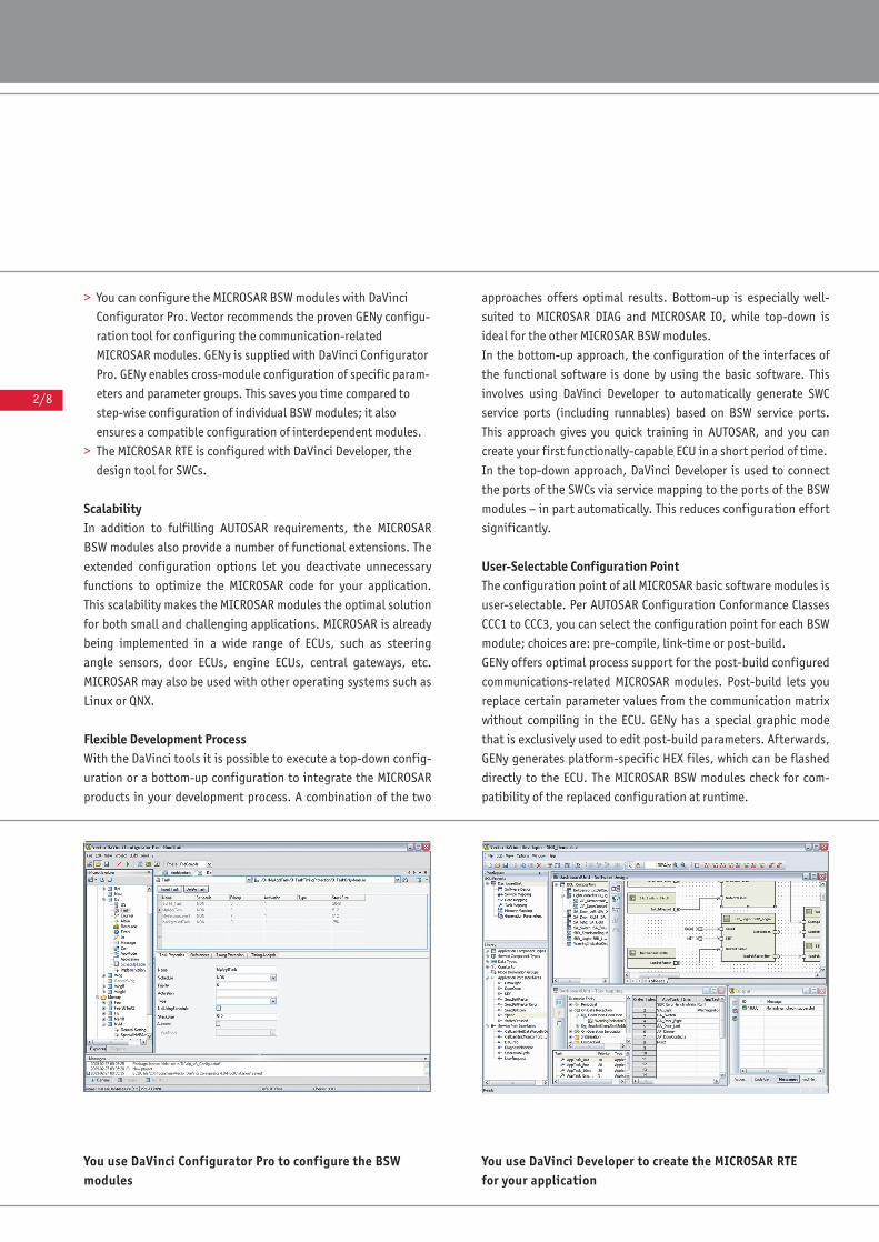
You use DaVinci Configurator Pro to configure the BSWmodules
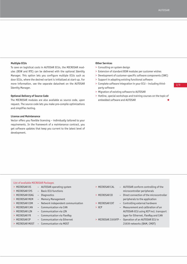
You use DaVinci Developer to create the MICROSAR RTEfor your application
2/9
AUTOSAR
Multiple ECUs To save on logistical costs in AUTOSAR ECUs, the MICROSAR mod-
ules (BSW and RTE) can be delivered with the optional Identity
Manager. This option lets you configure multiple ECUs such as
door ECUs, where the desired variant is initialized at start-up. For
more information, see the separate datasheet on the AUTOSAR
Identity Manager.
Optional Delivery of Source CodeThe MICROSAR modules are also available as source code, upon
request. The source code lets you make pre-compile optimizations
and simplifies testing.
License and MaintenanceVector offers you flexible licensing – individually tailored to your
requirements. In the framework of a maintenance contract, you
get software updates that keep you current to the latest level of
development.
Other Services> Consulting on system design
> Extension of standard BSW modules per customer wishes
> Development of customer-specific software components (SWC)
> Support in adapting existing functional software
> Complete software integration in your ECU – including third-
party software
> Migration of existing software to AUTOSAR
> Hotline, special workshops and training courses on the topic of
embedded software and AUTOSAR ◆
List of available MICROSAR Packages
> MICROSAR OS – AUTOSAR operating system
> MICROSAR SYS – Basic ECU functions
> MICROSAR DIAG – Diagnostics
> MICROSAR MEM – Memory Management
> MICROSAR COM – Network independent communication
> MICROSAR CAN – Communication via CAN
> MICROSAR LIN – Communication via LIN
> MICROSAR FR – Communication via FlexRay
> MICROSAR IP – Communication via Ethernet
> MICROSAR MOST – Communication via MOST
> MICROSAR CAL – AUTOSAR conform controlling of the
microcontroller peripherals
> MICROSAR IO – Direct connection of the microcontroller
peripherals to the application
> MICROSAR EXT – Controlling external hardware
> XCP – Measurement and calibration of an
AUTOSAR-ECU using XCP incl. transport
layer for Ethernet, FlexRay and CAN
> MICROSAR J1939TP – Operation of an AUTOSAR ECU in
J1939 networks (BAM, CMDT)
2/10
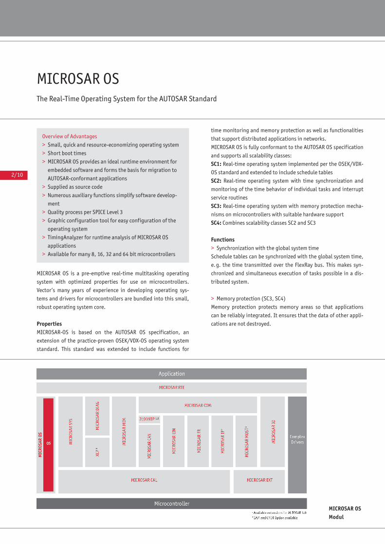
MICROSAR OSThe Real-Time Operating System for the AUTOSAR Standard
MICROSAR OS is a pre-emptive real-time multitasking operating
system with optimized properties for use on microcontrollers.
Vector’s many years of experience in developing operating sys-
tems and drivers for microcontrollers are bundled into this small,
robust operating system core.
PropertiesMICROSAR-OS is based on the AUTOSAR OS specification, an
extension of the practice-proven OSEK/VDX-OS operating system
standard. This standard was extended to include functions for
time monitoring and memory protection as well as functionalities
that support distributed applications in networks.
MICROSAR OS is fully conformant to the AUTOSAR OS specification
and supports all scalability classes:
SC1: Real-time operating system implemented per the OSEK/VDX-
OS standard and extended to include schedule tables
SC2: Real-time operating system with time synchronization and
monitoring of the time behavior of individual tasks and interrupt
service routines
SC3: Real-time operating system with memory protection mecha-
nisms on microcontrollers with suitable hardware support
SC4: Combines scalability classes SC2 and SC3
Functions> Synchronization with the global system time
Schedule tables can be synchronized with the global system time,
e.g. the time transmitted over the FlexRay bus. This makes syn-
chronized and simultaneous execution of tasks possible in a dis-
tributed system.
> Memory protection (SC3, SC4)
Memory protection protects memory areas so that applications
can be reliably integrated. It ensures that the data of other appli-
cations are not destroyed.
MICROSAR OSModul
Overview of Advantages
> Small, quick and resource-economizing operating system
> Short boot times
> MICROSAR OS provides an ideal runtime environment for
embedded software and forms the basis for migration to
AUTOSAR-conformant applications
> Supplied as source code
> Numerous auxiliary functions simplify software develop-
ment
> Quality process per SPICE Level 3
> Graphic configuration tool for easy configuration of the
operating system
> TimingAnalyzer for runtime analysis of MICROSAR OS
applications
> Available for many 8, 16, 32 and 64 bit microcontrollers
2/11
AUTOSAR
> Timing Protection (SC2, SC4)
Timing protection ensures that assumptions made in the early
design phase related to execution times are preserved during run-
time as well. When protection encounters a defective application
section, this does not have any negative effects on other running
applications.
> Execution time measurements (SC2, SC4)
You can use functions of scalability classes 2 and 4 to measure the
execution times and interrupt disable times of applications. These
measured data can later be used as practice-based values in
designing and integrating future applications.
> TimingAnalyzer Design Assistance
TimingAnalyzer design assistance computes the task execution
schedule, checks for conformance to execution time restrictions
and represents the schedule tables in a well-organized graphic
display. Analysis is performed for every task and every interrupt
with the following information: Priority, period, execution time
and end time. The graphic user interface visualizes system behav-
ior clearly and concisely.
Optional Extensions> High Resolution Timer
If resolutions finer than 1ms are needed for the timers, the mech-
anisms of the High Resolution Timer are advisable, which imple-
ment this precision without simultaneously increasing interrupt
load. Depending on the controller, this may enable resolutions
into the microseconds range.
> High Resolution Synchronization for Schedule Tables
In some applications, it is necessary to synchronize and trigger
schedule tables with very high precision using internal or external
signal sources. The “High Resolution Synchronization” option
gives you resolutions in the microsecond range without increasing
interrupt load.
Scope of Delivery> Operating system core as source code
> Graphic configuration and generation tool for Windows
NT/2000/XP/Vista
> Command line based generator (for Windows NT/2000/X/Vista)
> BSW modules description
> Description files for DaVinci Configurator Pro
> Documentation and sample programs with makefiles
> TimingAnalyzer ◆
The complete AUTOSAR solution from Vector
Vector offers a fully tuned solution for developing AUTOSAR
ECUs with its DaVinci and MICROSAR products.
You will find information on general properties of BSW mod-
ules from the MICROSAR packages as well as details on func-
tional features of the individual DaVinci Tools in separate
datasheets.
MICROSAR-OS conforms to AUTOSAR Specification 3.x
Additional Services
Vector offers you worldwide support related to AUTOSAR:
> Training events
> Design consulting
> Customer-specific implementations
> Hotline
> Software maintenance
The extent and form of all services are tailored to your wishes
and needs.
Training
In the framework of our training program we can offer vari-
ous training courses and workshops on MICROSAR at our
classrooms or at your business site.
For more information on individual training events and dates
please visit: www.vector-academy.com
Contact and AvailabilityFor information on the availability of hardware-specific MICROSAR BSW modules go to: www.microsar.com/availability/ We would be glad to provide you with information on OEM-specific versions and individual support for your AUTOSARprojects.Find your contact person at: www.vector.com/contact
2/12
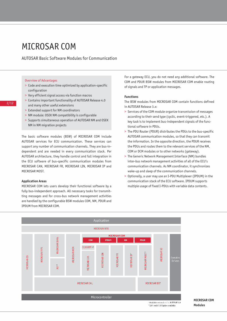
MICROSAR COMAUTOSAR Basic Software Modules for Communication
The basic software modules (BSW) of MICROSAR COM include
AUTOSAR services for ECU communication. These services can
support any number of communication channels. They are bus-in-
dependent and are needed in every communication stack. Per
AUTOSAR architecture, they handle control and full integration in
the ECU software of bus-specific communication modules from
MICROSAR CAN, MICROSAR FR, MICROSAR LIN, MICROSAR IP and
MICROSAR MOST.
Application AreasMICROSAR COM lets users develop their functional software by a
fully bus-independent approach. All necessary tasks for transmit-
ting messages and for cross-bus network management activities
are handled by the configurable BSW modules COM, NM, PDUR and
IPDUM from MICROSAR COM.
For a gateway ECU, you do not need any additional software. The
COM and PDUR BSW modules from MICROSAR COM enable routing
of signals and TP or application messages.
FunctionsThe BSW modules from MICROSAR COM contain functions defined
in AUTOSAR Release 3.x:
> Services of the COM module organize transmission of messages
according to their send type (cyclic, event-triggered, etc.). A
key task is to implement bus-independent signals of the func-
tional software in PDUs.
> The PDU Router (PDUR) distributes the PDUs to the bus-specific
AUTOSAR communication modules, so that they can transmit
the information. In the opposite direction, the PDUR receives
the PDUs and routes them to the relevant services of the NM,
COM or DCM modules or to other networks (gateway).
> The Generic Network Management Interface (NM) bundles
inter-bus network management activities of all of the ECU’s
communication channels. As NM coordinator, it synchronizes
wake-up and sleep of the communication channels.
> Optionally, a user may use an I-PDU Multiplexer (IPDUM) in the
communication stack of the ECU software. IPDUM supports
multiple usage of fixed I-PDUs with variable data contents.
MICROSAR COMModules
Overview of Advantages
> Code and execution time optimized by application-specific
configuration
> Very efficient signal access via function macros
> Contains important functionality of AUTOSAR Release 4.0
and many other useful extensions
> Extended support for NM coordinators
> NM module: OSEK NM compatibility is configurable
> Supports simultaneous operation of AUTOSAR NM and OSEK
NM in NM migration projects
2/13
AUTOSAR
The following functions are optionally available:
> COM: TX deadline monitoring
> PDUR: TP layer fan-out and zero cost operation
> PDUR: Transmit cancellation and change parameter request
Furthermore, the BSW modules from MICROSAR COM contain the
following functionalities. Some of them are part of AUTOSAR
Release 4.0 (ASR 4.0):
> COM: Indication and timeout flags for signals and signal groups
> COM: Signal conversion. This conversion may be configured
with an A2L ASAP2 database.
> COM: Invalidity declaration of TX signals in case of RX signal
timeout
> COM: Deactivation of the TX confirmation interrupt
> COM: Pre-compile optimizations such as function macros for
very efficient signal access
> COM, PDUR: Transport of long I-PDUs and signals via CANTP and
via J1939 as specified in ASR 4.0. Other TPs are available upon
request.
> COM: Extension by signal callout functions, e.g. to integrate
gateways as complex device drivers.
> PDUR: Generic interface for integrating a TP and bus communi-
cation as complex device driver
> PDUR: Intra-ECU communications for TP connections
> PDUR: Optimized routing per ASR 4.0 (e.g. with Burst Transmis-
sion) together with CANTP from MICORSAR CAN
> NM: Synchronous sleep and wake-up of multiple networks via
different NM coordinators
> NM: Backup coordinator
> NM: Pre-compile optimizations such as use of function macros
> NM: Support of OSEK NM (configurable)
> NM: Mixed operation of OSEK and AUTOSAR-NM on one channel
Scope of Delivery> Software modules as library with C header files, optionally as
source code
> Command line based generator (for Windows NT/2000/XP/Vista)
> BSW modules description
> DLLs for configuration with GENy
> Documentation and sample programs with makefiles
◆
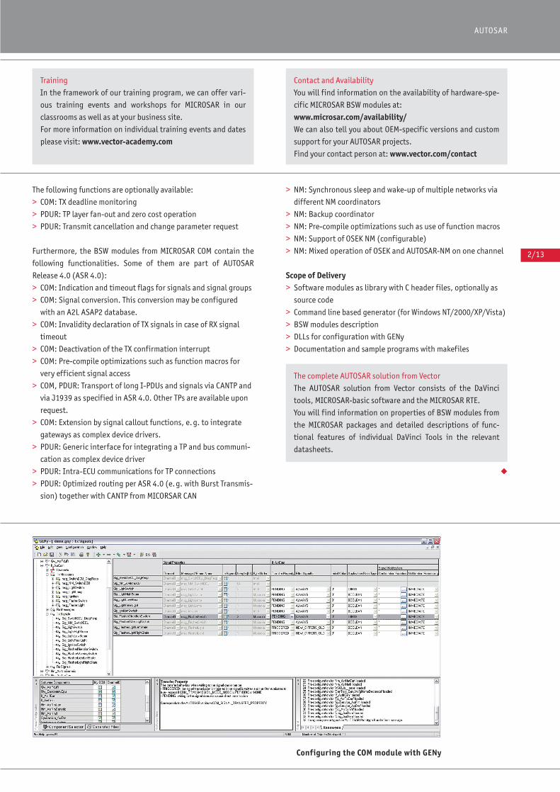
Configuring the COM module with GENy
Training
In the framework of our training program, we can offer vari-
ous training events and workshops for MICROSAR in our
classrooms as well as at your business site.
For more information on individual training events and dates
please visit: www.vector-academy.com
Contact and Availability
You will find information on the availability of hardware-spe-
cific MICROSAR BSW modules at:
www.microsar.com/availability/ We can also tell you about OEM-specific versions and custom
support for your AUTOSAR projects.
Find your contact person at: www.vector.com/contact
The complete AUTOSAR solution from Vector
The AUTOSAR solution from Vector consists of the DaVinci
tools, MICROSAR-basic software and the MICROSAR RTE.
You will find information on properties of BSW modules from
the MICROSAR packages and detailed descriptions of func-
tional features of individual DaVinci Tools in the relevant
datasheets.
2/14
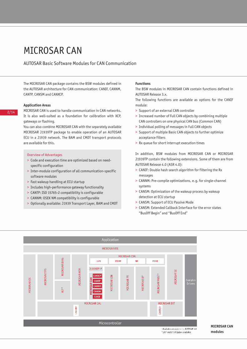
MICROSAR CANAUTOSAR Basic Software Modules for CAN Communication
The MICROSAR CAN package contains the BSW modules defined in
the AUTOSAR architecture for CAN communication: CANIF, CANNM,
CANTP, CANSM and CANXCP.
Application AreasMICROSAR CAN is used to handle communication in CAN networks.
It is also well-suited as a foundation for calibration with XCP,
gateways or flashing.
You can also combine MICROSAR CAN with the separately available
MICROSAR J1939TP package to enable operation of an AUTOSAR
ECU in a J1939 network. The BAM and CMDT transport protocols
are available for this.
FunctionsThe BSW modules in MICROSAR CAN contain functions defined in
AUTOSAR Release 3.x.
The following functions are available as options for the CANIF
module:
> Support of an external CAN controller
> Increased number of Full CAN objects by combining multiple
CAN controllers on one physical CAN bus (Common CAN)
> Individual polling of messages in Full CAN objects
> Support of multiple Basic CAN objects to further optimize
acceptance filters
> Rx queue for short interrupt execution times
In addition, BSW modules from MICROSAR CAN or MICROSAR
J1939TP contain the following extensions. Some of them are from
AUTOSAR Release 4.0 (ASR 4.0):
> CANIF: Double hash search algorithm for filtering the Rx
messages
> CANNM: Pre-compile optimizations, e.g. for single-channel
systems
> CANSM: Optimization of the wakeup process by wakeup
detection at ECU startup
> CANSM: Support of ECU Passive Mode
> CANSM: Extended Callback Interface for the error states
“BusOff Begin” and “BusOff End”
MICROSAR CANmodules
Overview of Advantages
> Code and execution time are optimized based on need-
specific configuration
> Inter-module configuration of all communication-specific
software modules
> Fast wakeup handling at ECU startup
> Includes high-performance gateway functionality
> CANTP: ISO 15765-2 compatibility is configurable
> CANNM: OSEK NM compatibility is configurable
> Optionally available: J1939 Transport Layer, BAM and CMDT
2/15
AUTOSAR
> CANSM: Checks whether states were successfully set in the CAN
driver (CANDRV) or CAN transceiver driver (CANTRCV). In case of
error, an automatic repetition is executed.
> CANTP: Supports full duplex communication
> CANTP: Supports mixed addressing (11 bit CAN ID); typically for
CAN/LIN gateway applications
> CANTP: Optimized routing per ASR 4.0 (e.g. with Burst Trans-
mission) together with the PDUR from MICORSAR COM.
> CANTP: ISO 15765-2 compatibility is configurable
> CANTP: Sets BlockSize and STmin at runtime
> BAM and CMDT: Transport protocols for J1939 networks
available as option
Scope of Delivery> Software modules as library with C header files, optionally as
source code
> Command line based generator (for Windows NT/2000/XP/
Vista)
> BSW modules description
> DLLs for configuration with GENy
> Documentation and sample programs with makefiles
Other MICROSAR Products for a Complete CAN CommunicationStackBased on the AUTOSAR architecture, a complete communication
stack for CAN can be formed using MICROSAR CAN together with
the BSW modules from the separately available MICROSAR COM,
MICROSAR CAL and MICROSAR EXT packages. To interface
MICROSAR CAN to the application and the hardware, you will still
need the following BSW modules:
> Hardware-specific CAN driver (CANDRV) from MICROSAR CAL
> Hardware-specific transceiver control (CANTRCV) from
MICROSAR EXT
> General communication modules (COM, NM, PDUR, IPDUM) from
MICROSAR COM
Modules in MICROSAR CAL and MICROSAR EXT are available for
many microcontrollers and transceivers.
Other relevant MICROSAR Products for CAN> DCM and DEM from MICROSAR DIAG
> DET, ECUM and COMM from MICROSAR SYS
> XCP ◆
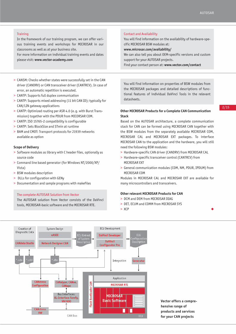
Vector offers a compre-hensive range of products and services for your CAN projects
Training
In the framework of our training program, we can offer vari-
ous training events and workshops for MICROSAR in our
classrooms as well as at your business site.
For more information on individual training events and dates
please visit: www.vector-academy.com
Contact and Availability
You will find information on the availability of hardware-spe-
cific MICROSAR BSW modules at:
www.microsar.com/availability/ We can also tell you about OEM-specific versions and custom
support for your AUTOSAR projects.
Find your contact person at: www.vector.com/contact
The complete AUTOSAR Solution from Vector
The AUTOSAR solution from Vector consists of the DaVinci
tools, MICROSAR-basic software and the MICROSAR RTE.
You will find information on properties of BSW modules from
the MICROSAR packages and detailed descriptions of func-
tional features of individual DaVinci Tools in the relevant
datasheets.
2/16
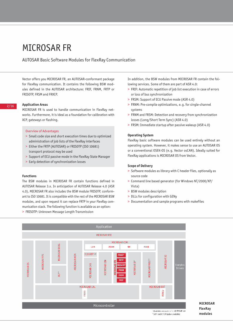
MICROSAR FRAUTOSAR Basic Software Modules for FlexRay Communication
Vector offers you MICROSAR FR, an AUTOSAR-conformant package
for FlexRay communication. It contains the following BSW mod-
ules defined in the AUTOSAR architecture: FRIF, FRNM, FRTP or
FRISOTP, FRSM and FRXCP.
Application AreasMICROSAR FR is used to handle communication in FlexRay net-
works. Furthermore, it is ideal as a foundation for calibration with
XCP, gateways or flashing.
FunctionsThe BSW modules in MICROSAR FR contain functions defined in
AUTOSAR Release 3.x. In anticipation of AUTOSAR Release 4.0 (ASR
4.0), MICROSAR FR also includes the BSW module FRISOTP, conform-
ant to ISO 10681. It is compatible with the rest of the MICROSAR BSW
modules, and upon request it can replace FRTP in your FlexRay com-
munication stack. The following function is available as an option:
> FRISOTP: Unknown Message Length Transmission
In addition, the BSW modules from MICROSAR FR contain the fol-
lowing services. Some of them are part of ASR 4.0:
> FRIF: Automatic repetition of job list execution in case of errors
or loss of bus synchronization
> FRSM: Support of ECU Passive mode (ASR 4.0)
> FRNM: Pre-compile optimizations, e.g. for single-channel
systems
> FRNM and FRSM: Detection and recovery from synchronization
losses (Long/Short Term Sync) (ASR 4.0)
> FRSM: Immediate startup after passive wakeup (ASR 4.0)
Operating SystemFlexRay basic software modules can be used entirely without an
operating system. However, it makes sense to use an AUTOSAR OS
or a conventional OSEK-OS (e.g. Vector osCAN). Ideally suited for
FlexRay applications is MICROSAR OS from Vector.
Scope of Delivery> Software modules as library with C header files, optionally as
source code
> Command line based generator (for Windows NT/2000/XP/
Vista)
> BSW modules description
> DLLs for configuration with GENy
> Documentation and sample programs with makefiles
MICROSARFlexRay modules
Overview of Advantages
> Small code size and short execution times due to optimized
administration of job lists of the FlexRay interfaces
> Either the FRTP (AUTOSAR) or FRISOTP (ISO 10681)
transport protocol may be used
> Support of ECU passive mode in the FlexRay State Manager
> Early detection of synchronization losses
2/17
AUTOSAR
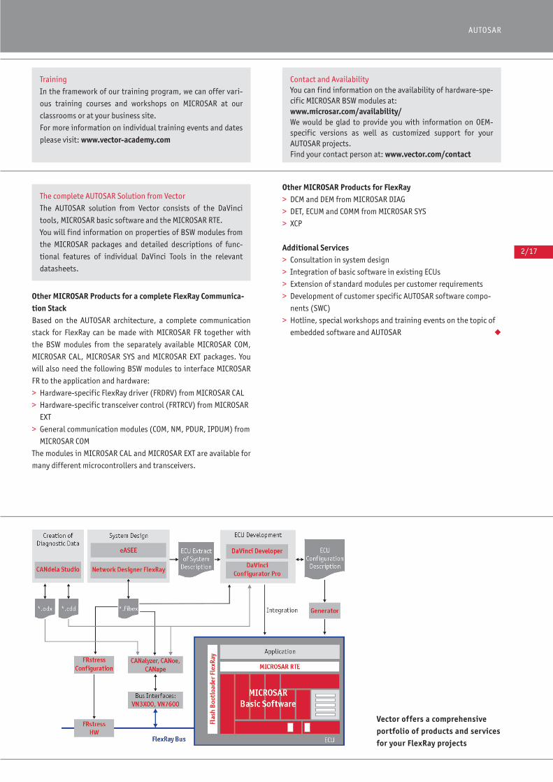
Other MICROSAR Products for a complete FlexRay Communica-tion StackBased on the AUTOSAR architecture, a complete communication
stack for FlexRay can be made with MICROSAR FR together with
the BSW modules from the separately available MICROSAR COM,
MICROSAR CAL, MICROSAR SYS and MICROSAR EXT packages. You
will also need the following BSW modules to interface MICROSAR
FR to the application and hardware:
> Hardware-specific FlexRay driver (FRDRV) from MICROSAR CAL
> Hardware-specific transceiver control (FRTRCV) from MICROSAR
EXT
> General communication modules (COM, NM, PDUR, IPDUM) from
MICROSAR COM
The modules in MICROSAR CAL and MICROSAR EXT are available for
many different microcontrollers and transceivers.
Other MICROSAR Products for FlexRay> DCM and DEM from MICROSAR DIAG
> DET, ECUM and COMM from MICROSAR SYS
> XCP
Additional Services> Consultation in system design
> Integration of basic software in existing ECUs
> Extension of standard modules per customer requirements
> Development of customer specific AUTOSAR software compo-
nents (SWC)
> Hotline, special workshops and training events on the topic of
embedded software and AUTOSAR ◆
Vector offers a comprehensiveportfolio of products and servicesfor your FlexRay projects
Training
In the framework of our training program, we can offer vari-
ous training courses and workshops on MICROSAR at our
classrooms or at your business site.
For more information on individual training events and dates
please visit: www.vector-academy.com
Contact and AvailabilityYou can find information on the availability of hardware-spe-cific MICROSAR BSW modules at: www.microsar.com/availability/ We would be glad to provide you with information on OEM-specific versions as well as customized support for yourAUTOSAR projects.Find your contact person at: www.vector.com/contact
The complete AUTOSAR Solution from Vector
The AUTOSAR solution from Vector consists of the DaVinci
tools, MICROSAR basic software and the MICROSAR RTE.
You will find information on properties of BSW modules from
the MICROSAR packages and detailed descriptions of func-
tional features of individual DaVinci Tools in the relevant
datasheets.
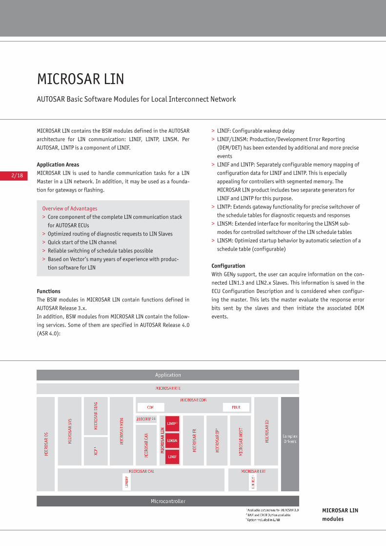
2/18
MICROSAR LINAUTOSAR Basic Software Modules for Local Interconnect Network
MICROSAR LIN contains the BSW modules defined in the AUTOSAR
architecture for LIN communication: LINIF, LINTP, LINSM. Per
AUTOSAR, LINTP is a component of LINIF.
Application AreasMICROSAR LIN is used to handle communication tasks for a LIN
Master in a LIN network. In addition, it may be used as a founda-
tion for gateways or flashing.
Functions The BSW modules in MICROSAR LIN contain functions defined in
AUTOSAR Release 3.x.
In addition, BSW modules from MICROSAR LIN contain the follow-
ing services. Some of them are specified in AUTOSAR Release 4.0
(ASR 4.0):
> LINIF: Configurable wakeup delay
> LINIF/LINSM: Production/Development Error Reporting
(DEM/DET) has been extended by additional and more precise
events
> LINIF and LINTP: Separately configurable memory mapping of
configuration data for LINIF and LINTP. This is especially
appealing for controllers with segmented memory. The
MICROSAR LIN product includes two separate generators for
LINIF and LINTP for this purpose.
> LINTP: Extends gateway functionality for precise switchover of
the schedule tables for diagnostic requests and responses
> LINSM: Extended interface for monitoring the LINSM sub-
modes for controlled switchover of the LIN schedule tables
> LINSM: Optimized startup behavior by automatic selection of a
schedule table (configurable)
Configuration With GENy support, the user can acquire information on the con-
nected LIN1.3 and LIN2.x Slaves. This information is saved in the
ECU Configuration Description and is considered when configur-
ing the master. This lets the master evaluate the response error
bits sent by the slaves and then initiate the associated DEM
events.
MICROSAR LINmodules
Overview of Advantages
> Core component of the complete LIN communication stack
for AUTOSAR ECUs
> Optimized routing of diagnostic requests to LIN Slaves
> Quick start of the LIN channel
> Reliable switching of schedule tables possible
> Based on Vector’s many years of experience with produc-
tion software for LIN

2/19
AUTOSAR
Scope of Delivery> Software modules as library with C header files, optionally as
source code
> Command line based generator (for Windows NT/2000/XP/
Vista)
> BSW modules description
> DLLs for configuration with GENy
> Documentation and sample programs with makefiles
Other MICROSAR Products for a Complete LIN CommunicationStackBased on the AUTOSAR architecture, a complete communication
stack for LIN is formed by MICROSAR LIN together with the BSW
modules from the separately available MICROSAR COM, MICROSAR
CAL and MICROSAR EXT packages. To interface MICROSAR LIN to
the application and hardware, you will still need the following
BSW modules:
> Hardware-specific LIN driver (LINDRV) from MICROSAR CAL
> Hardware-specific transceiver control (LINTRCV) from
MICROSAR EXT
> General communication modules (COM, PDUR) from MICROSAR
COM
The modules in MICROSAR CAL and MICROSAR EXT are available for
many different microcontrollers and transceivers.
Other Relevant MICROSAR Products for LIN> DET, ECUM and COMM from MICROSAR SYS ◆
Vector offers you a comprehensiverange of products and services foryour LIN projects
Training
In the framework of our training program we can offer vari-
ous training courses and workshops on MICROSAR at our
classrooms or at your business site.
For more information on individual training events and dates
please visit: www.vector-academy.com
Contact and AvailabilityFor information on the availability of hardware-specific MICROSAR BSW modules go to: www.microsar.com/availability/ We would be glad to provide you with information on OEM-specific versions and individual support for your AUTOSARprojects.Find your contact person at: www.vector.com/contact
The complete AUTOSAR Solution from Vector
The AUTOSAR solution from Vector consists of the DaVinci
tools, MICROSAR-basic software and the MICROSAR RTE.
You will find information on properties of BSW modules from
the MICROSAR packages and detailed descriptions of func-
tional features of individual DaVinci Tools in the relevant
datasheets.
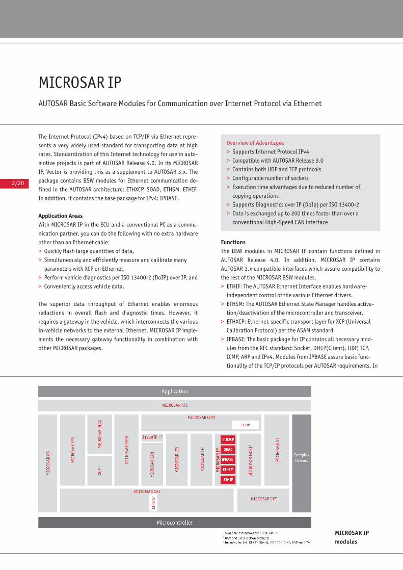
2/20
MICROSAR IPAUTOSAR Basic Software Modules for Communication over Internet Protocol via Ethernet
The Internet Protocol (IPv4) based on TCP/IP via Ethernet repre-
sents a very widely used standard for transporting data at high
rates. Standardization of this Internet technology for use in auto-
motive projects is part of AUTOSAR Release 4.0. In its MICROSAR
IP, Vector is providing this as a supplement to AUTOSAR 3.x. The
package contains BSW modules for Ethernet communication de-
fined in the AUTOSAR architecture: ETHXCP, SOAD, ETHSM, ETHIF.
In addition, it contains the base package for IPv4: IPBASE.
Application AreasWith MICROSAR IP in the ECU and a conventional PC as a commu-
nication partner, you can do the following with no extra hardware
other than an Ethernet cable:
> Quickly flash large quantities of data,
> Simultaneously and efficiently measure and calibrate many
parameters with XCP on Ethernet,
> Perform vehicle diagnostics per ISO 13400-2 (DoIP) over IP, and
> Conveniently access vehicle data.
The superior data throughput of Ethernet enables enormous
reductions in overall flash and diagnostic times. However, it
requires a gateway in the vehicle, which interconnects the various
in-vehicle networks to the external Ethernet. MICROSAR IP imple-
ments the necessary gateway functionality in combination with
other MICROSAR packages.
FunctionsThe BSW modules in MICROSAR IP contain functions defined in
AUTOSAR Release 4.0. In addition, MICROSAR IP contains
AUTOSAR 3.x compatible interfaces which assure compatibility to
the rest of the MICROSAR BSW modules.
> ETHIF: The AUTOSAR Ethernet Interface enables hardware-
independent control of the various Ethernet drivers.
> ETHSM: The AUTOSAR Ethernet State Manager handles activa-
tion/deactivation of the microcontroller and transceiver.
> ETHXCP: Ethernet-specific transport layer for XCP (Universal
Calibration Protocol) per the ASAM standard
> IPBASE: The basic package for IP contains all necessary mod-
ules from the RFC standard: Socket, DHCP(Client), UDP, TCP,
ICMP, ARP and IPv4. Modules from IPBASE assure basic func-
tionality of the TCP/IP protocols per AUTOSAR requirements. In
Overview of Advantages
> Supports Internet Protocol IPv4
> Compatible with AUTOSAR Release 3.0
> Contains both UDP and TCP protocols
> Configurable number of sockets
> Execution time advantages due to reduced number of
copying operations
> Supports Diagnostics over IP (DoIp) per ISO 13400-2
> Data is exchanged up to 200 times faster than over a
conventional High-Speed CAN interface
MICROSAR IPmodules
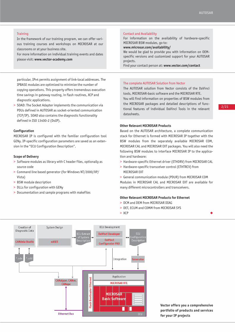
2/21
AUTOSAR
particular, IPv4 permits assignment of link-local addresses. The
IPBASE modules are optimized to minimize the number of
copying operations. This property offers tremendous execution
time savings in gateway routing, in flash routines, XCP and
diagnostic applications.
> SOAD: The Socket Adapter implements the communication via
PDUs defined in AUTOSAR as socket-oriented communication
(TCP/IP). SOAD also contains the diagnostic functionality
defined in ISO 13400-2 (DoIP).
ConfigurationMICROSAR IP is configured with the familiar configuration tool
GENy. IP-specific configuration parameters are saved as an exten-
sion in the “ECU Configuration Description”.
Scope of Delivery> Software modules as library with C header files, optionally as
source code
> Command line based generator (for Windows NT/2000/XP/
Vista)
> BSW module description
> DLLs for configuration with GENy
> Documentation and sample programs with makefiles
Other Relevant MICROSAR ProductsBased on the AUTOSAR architecture, a complete communication
stack for Ethernet is formed with MICROSAR IP together with the
BSW modules from the separately available MICROSAR COM,
MICROSAR CAL and MICROSAR EXT packages. You will also need the
following BSW modules to interface MICROSAR IP to the applica-
tion and hardware:
> Hardware-specific Ethernet driver (ETHDRV) from MICROSAR CAL
> Hardware-specific transceiver control (ETHTRCV) from
MICROSAR EXT
> General communication module (PDUR) from MICROSAR COM
Modules in MICROSAR CAL and MICROSAR EXT are available for
many different microcontrollers and transceivers.
Other Relevant MICROSAR Products for Ethernet> DCM and DEM from MICROSAR DIAG
> DET, ECUM and COMM from MICROSAR SYS
> XCP ◆
Training
In the framework of our training program, we can offer vari-
ous training courses and workshops on MICROSAR at our
classrooms or at your business site.
For more information on individual training events and dates
please visit: www.vector-academy.com
Contact and AvailabilityFor information on the availability of hardware-specific MICROSAR BSW modules, go to: www.microsar.com/availability/ We would be glad to provide you with information on OEM-specific versions and customized support for your AUTOSARprojects.Find your contact person at: www.vector.com/contact
The complete AUTOSAR Solution from Vector
The AUTOSAR solution from Vector consists of the DaVinci
tools, MICROSAR-basic software and the MICROSAR RTE.
You will find information on properties of BSW modules from
the MICROSAR packages and detailed descriptions of func-
tional features of individual DaVinci Tools in the relevant
datasheets.
Vector offers you a comprehensiveportfolio of products and servicesfor your IP projects
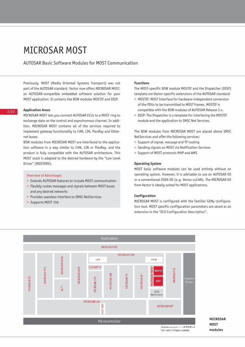
2/22
MICROSAR MOST AUTOSAR Basic Software Modules for MOST Communication
Previously, MOST (Media Oriented Systems Transport) was not
part of the AUTOSAR standard. Vector now offers MICROSAR MOST,
an AUTOSAR-compatible embedded software solution for your
MOST application. It contains the BSW modules MOSTIF and DISP.
Application AreasMICROSAR MOST lets you connect AUTOSAR ECUs to a MOST ring to
exchange data on the control and asynchronous channel. In addi-
tion, MICROSAR MOST contains all of the services required to
implement gateway functionality to CAN, LIN, FlexRay and Ether-
net buses.
BSW modules from MICROSAR MOST are interfaced to the applica-
tion software in a way similar to CAN, LIN or FlexRay, and the
product is fully compatible with the AUTOSAR architecture. This
MOST stack is adapted to the desired hardware by the “Low Level
Driver” (MOSTDRV).
FunctionsThe MOST-specific BSW module MOSTIF and the Dispatcher (DISP)
template are Vector-specific extensions of the AUTOSAR standard:
> MOSTIF: MOST Interface for hardware-independent conversion
of the PDUs to be transmitted to MOST frames. MOSTIF is
compatible with the BSW modules of AUTOSAR Release 3.x.
> DISP: The Dispatcher is a template for interfacing the MOSTIF
module and the application to SMSC Net Services.
The BSW modules from MICROSAR MOST are placed above SMSC
NetServices and offer the following services:
> Support of signal, message and TP routing
> Sending signals on MOST via Notification Services
> Support of MOST protocols MHP and AMS
Operating SystemMOST basic software modules can be used entirely without an
operating system. However, it is advisable to use an AUTOSAR OS
or a conventional OSEK-OS (e.g. Vector osCAN). The MICROSAR OS
from Vector is ideally suited for MOST applications.
ConfigurationMICROSAR MOST is configured with the familiar GENy configura-
tion tool. MOST specific configuration parameters are saved as an
extension in the “ECU Configuration Description”.
MICROSARMOST modules
Overview of Advantages
> Extends AUTOSAR features to include MOST communication
> Flexibly routes messages and signals between MOST buses
and any desired networks
> Provides seamless interface to SMSC NetServices
> Supports MOST 150
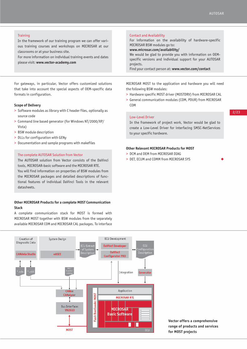
2/23
AUTOSAR
For gateways, in particular, Vector offers customized solutions
that take into account the special aspects of OEM-specific data
formats in configuration.
Scope of Delivery> Software modules as library with C header files, optionally as
source code
> Command line based generator (for Windows NT/2000/XP/
Vista)
> BSW module description
> DLLs for configuration with GENy
> Documentation and sample programs with makefiles
Other MICROSAR Products for a complete MOST CommunicationStackA complete communication stack for MOST is formed with
MICROSAR MOST together with BSW modules from the separately
available MICROSAR COM and MICROSAR CAL packages. To interface
MICROSAR MOST to the application and hardware you will need
the following BSW modules:
> Hardware specific MOST driver (MOSTDRV) from MICROSAR CAL
> General communication modules (COM, PDUR) from MICROSAR
COM
Other Relevant MICROSAR Products for MOST> DCM and DEM from MICROSAR DIAG
> DET, ECUM and COMM from MICROSAR SYS ◆
Vector offers a comprehensiverange of products and servicesfor MOST projects
Training
In the framework of our training program we can offer vari-
ous training courses and workshops on MICROSAR at our
classrooms or at your business site.
For more information on individual training events and dates
please visit: www.vector-academy.com
Contact and AvailabilityFor information on the availability of hardware-specific MICROSAR BSW modules go to: www.microsar.com/availability/ We would be glad to provide you with information on OEM-specific versions and individual support for your AUTOSARprojects.Find your contact person at: www.vector.com/contact
The complete AUTOSAR Solution from Vector
The AUTOSAR solution from Vector consists of the DaVinci
tools, MICROSAR-basic software and the MICROSAR RTE.
You will find information on properties of BSW modules from
the MICROSAR packages and detailed descriptions of func-
tional features of individual DaVinci Tools in the relevant
datasheets.
Low-Level Driver
In the framework of project work, Vector would be glad to
create a Low-Level Driver for interfacing SMSC-NetServices
to your specific hardware.

EMBEDDED SOFTWARE
More Information: www.vector.com/contact
V2.3
201
0-06
Overview of Advantages
> Exceptionally secure data transactions
> Efficient data accesses
> Efficient and robust management of nonvolatile memories
> Redundant storage of management data increases reliability of data
access
> Inter-module configuration of the entire memory stack
> Platform-optimized memory stack solution from a single source
The MICROSAR MEM package contains all of the AUTOSAR modules
for memory management: NVM, MEMIF, EA and FEE. They support
management, checking and restoring of data from nonvolatile
memories (Flash or EEPROM). The Basic Software Modules (BSW)
from MICROSAR MEM are fast, reliable and robust.
Application Areas MICROSAR MEM lets you develop your functional software plat-
form-independently. MICROSAR MEM contains AUTOSAR services
for reading, writing and erasing persistent application data in
flash and/or EEPROM memories. This gives the functional software
hardware-independent access to memory. The application does not
need to know the specific type of memory that exists on the plat-
form or whether this memory is internal to the controller or exter-
nally connected to it.
Functions The BSW modules in MICROSAR MEM contain functions defined in
AUTOSAR Release 3.x.
In each memory stack, you will need the BSW modules NVM and
MEMIF from MICROSAR MEM. They handle block-oriented and
technology-independent access to the memory areas − without
requiring prior knowledge of memory attributes.
Your memory stack will need additional BSW modules, depending
on the use case:
> When using a flash memory, you need the Flash EEPROM Emula-
tion (FEE) module from MICROSAR MEM as well as a flash driver
(FLSDRV) from MICROSAR CAL that is suitable for your hardware.
> When using an EEPROM, you need the EEPROM Abstraction (EA)
module from MICROSAR MEM as well as an EEPROM driver
(EEPDRV) from MICROSAR CAL that is suitable for your hardware.
For special requirements, Vector offers platform-optimized solu-
tions, e.g. for using the EA BSW module in data flashing or opti-
mizing the FEE module for specific hardware.
The following functions are optionally available: > NVM: Block type �DATASET_ROM� with multiple ROM blocks
> NVM: Data protection with CRC8
In addition, MICROSAR MEM contains the following extensions;
some are from AUTOSAR Release 4.0 (ASR 4.0):
> NVM: Allocates RAM for CRC memory storage
MICROSAR MEM AUTOSAR Basic Software Modules for Memory Management
MICROSAR MEM modules
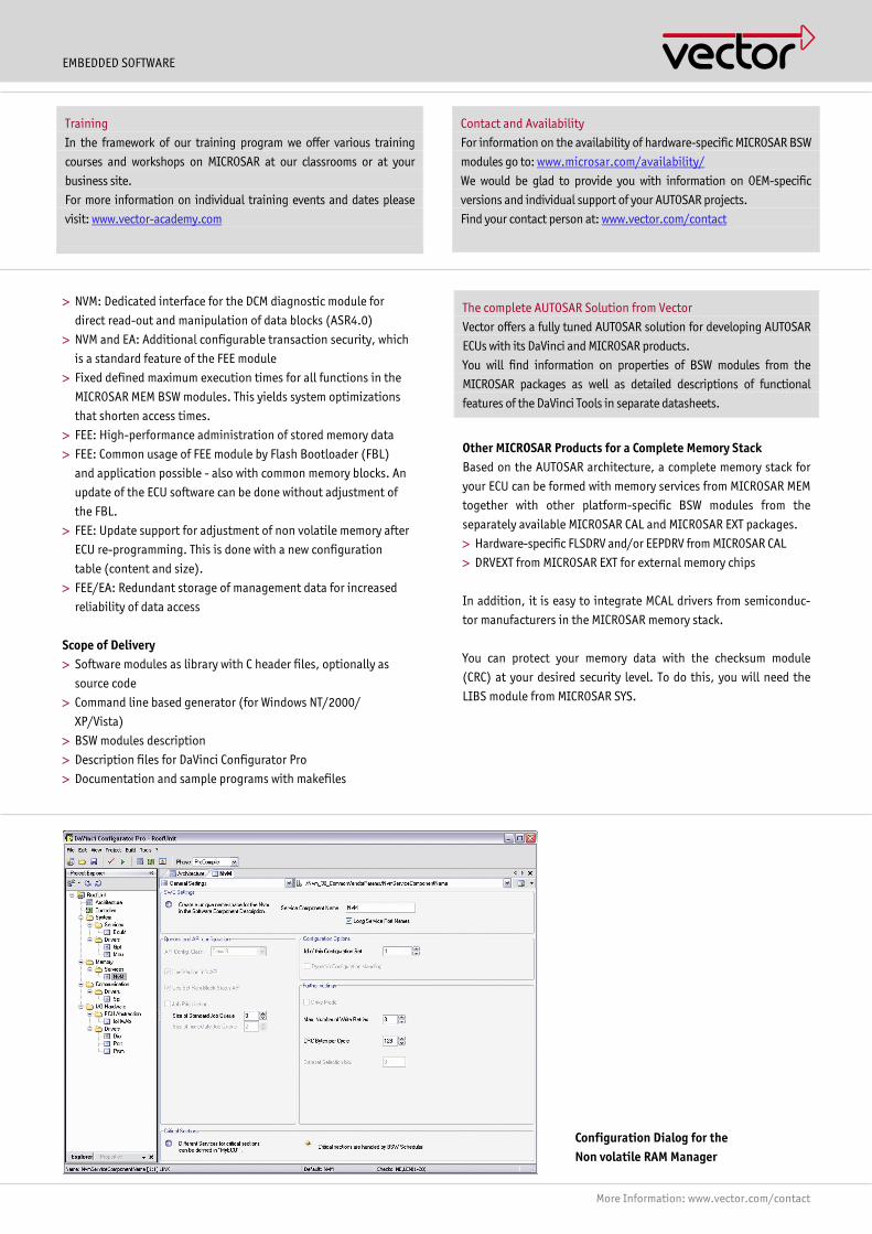
EMBEDDED SOFTWARE
More Information: www.vector.com/contact
Contact and Availability
For information on the availability of hardware-specific MICROSAR BSW
modules go to: www.microsar.com/availability/
We would be glad to provide you with information on OEM-specific
versions and individual support of your AUTOSAR projects.
Find your contact person at: www.vector.com/contact
Training
In the framework of our training program we offer various training
courses and workshops on MICROSAR at our classrooms or at your
business site.
For more information on individual training events and dates please
visit: www.vector-academy.com
Configuration Dialog for the Non volatile RAM Manager
> NVM: Dedicated interface for the DCM diagnostic module for
direct read-out and manipulation of data blocks (ASR4.0)
> NVM and EA: Additional configurable transaction security, which
is a standard feature of the FEE module
> Fixed defined maximum execution times for all functions in the
MICROSAR MEM BSW modules. This yields system optimizations
that shorten access times.
> FEE: High-performance administration of stored memory data
> FEE: Common usage of FEE module by Flash Bootloader (FBL)
and application possible - also with common memory blocks. An
update of the ECU software can be done without adjustment of
the FBL.
> FEE: Update support for adjustment of non volatile memory after
ECU re-programming. This is done with a new configuration
table (content and size).
> FEE/EA: Redundant storage of management data for increased
reliability of data access
Scope of Delivery > Software modules as library with C header files, optionally as
source code
> Command line based generator (for Windows NT/2000/
XP/Vista)
> BSW modules description
> Description files for DaVinci Configurator Pro
> Documentation and sample programs with makefiles
The complete AUTOSAR Solution from Vector
Vector offers a fully tuned AUTOSAR solution for developing AUTOSAR
ECUs with its DaVinci and MICROSAR products.
You will find information on properties of BSW modules from the
MICROSAR packages as well as detailed descriptions of functional
features of the DaVinci Tools in separate datasheets.
Other MICROSAR Products for a Complete Memory Stack Based on the AUTOSAR architecture, a complete memory stack for
your ECU can be formed with memory services from MICROSAR MEM
together with other platform-specific BSW modules from the
separately available MICROSAR CAL and MICROSAR EXT packages.
> Hardware-specific FLSDRV and/or EEPDRV from MICROSAR CAL
> DRVEXT from MICROSAR EXT for external memory chips
In addition, it is easy to integrate MCAL drivers from semiconduc-
tor manufacturers in the MICROSAR memory stack.
You can protect your memory data with the checksum module
(CRC) at your desired security level. To do this, you will need the
LIBS module from MICROSAR SYS.
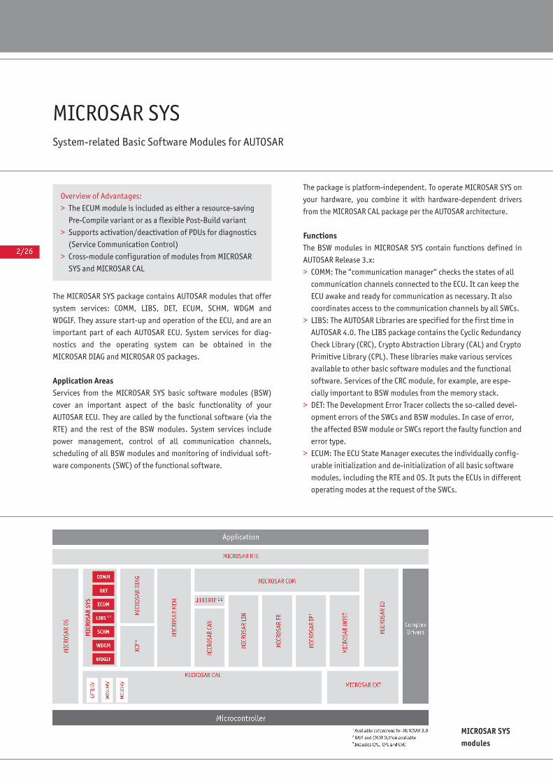
2/26
MICROSAR SYSSystem-related Basic Software Modules for AUTOSAR
The MICROSAR SYS package contains AUTOSAR modules that offer
system services: COMM, LIBS, DET, ECUM, SCHM, WDGM and
WDGIF. They assure start-up and operation of the ECU, and are an
important part of each AUTOSAR ECU. System services for diag-
nostics and the operating system can be obtained in the
MICROSAR DIAG and MICROSAR OS packages.
Application AreasServices from the MICROSAR SYS basic software modules (BSW)
cover an important aspect of the basic functionality of your
AUTOSAR ECU. They are called by the functional software (via the
RTE) and the rest of the BSW modules. System services include
power management, control of all communication channels,
scheduling of all BSW modules and monitoring of individual soft-
ware components (SWC) of the functional software.
The package is platform-independent. To operate MICROSAR SYS on
your hardware, you combine it with hardware-dependent drivers
from the MICROSAR CAL package per the AUTOSAR architecture.
FunctionsThe BSW modules in MICROSAR SYS contain functions defined in
AUTOSAR Release 3.x:
> COMM: The “communication manager“ checks the states of all
communication channels connected to the ECU. It can keep the
ECU awake and ready for communication as necessary. It also
coordinates access to the communication channels by all SWCs.
> LIBS: The AUTOSAR Libraries are specified for the first time in
AUTOSAR 4.0. The LIBS package contains the Cyclic Redundancy
Check Library (CRC), Crypto Abstraction Library (CAL) and Crypto
Primitive Library (CPL). These libraries make various services
available to other basic software modules and the functional
software. Services of the CRC module, for example, are espe-
cially important to BSW modules from the memory stack.
> DET: The Development Error Tracer collects the so-called devel-
opment errors of the SWCs and BSW modules. In case of error,
the affected BSW module or SWCs report the faulty function and
error type.
> ECUM: The ECU State Manager executes the individually config-
urable initialization and de-initialization of all basic software
modules, including the RTE and OS. It puts the ECUs in different
operating modes at the request of the SWCs.
MICROSAR SYSmodules
Overview of Advantages:
> The ECUM module is included as either a resource-saving
Pre-Compile variant or as a flexible Post-Build variant
> Supports activation/deactivation of PDUs for diagnostics
(Service Communication Control)
> Cross-module configuration of modules from MICROSAR
SYS and MICROSAR CAL
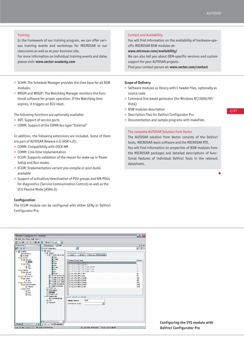
2/27
AUTOSAR
> SCHM: The Schedule Manager provides the time base for all BSW
modules.
> WDGM and WDGIF: The Watchdog Manager monitors the func-
tional software for proper operation. If the Watchdog time
expires, it triggers an ECU reset.
The following functions are optionally available:
> DET: Support of service ports
> COMM: Support of the COMM bus type “Internal”
In addition, the following extensions are included. Some of them
are part of AUTOSAR Release 4.0 (ASR 4.0):
> COMM: Compatibility with OSEK NM
> COMM: Link-time implementation
> ECUM: Supports validation of the reason for wake-up in Power
SetUp and Run modes
> ECUM: Implementation variant pre-compile or post-build
available
> Support of activation/deactivation of PDU groups and NM-PDUs
for diagnostics (Service Communication Control) as well as the
ECU Passive Mode (ASR4.0)
ConfigurationThe ECUM module can be configured with either GENy or DaVinci
Configurator Pro.
Scope of Delivery> Software modules as library with C header files, optionally as
source code
> Command line based generator (for Windows NT/2000/XP/
Vista)
> BSW modules description
> Description files for DaVinci Configurator Pro
> Documentation and sample programs with makefiles
◆
Configuring the SYS module withDaVinci Configurator Pro
Training
In the framework of our training program, we can offer vari-
ous training events and workshops for MICROSAR in our
classrooms as well as at your business site.
For more information on individual training events and dates
please visit: www.vector-academy.com
Contact and Availability
You will find information on the availability of hardware-spe-
cific MICROSAR BSW modules at:
www.microsar.com/availability/ We can also tell you about OEM-specific versions and custom
support for your AUTOSAR projects.
Find your contact person at: www.vector.com/contact
The complete AUTOSAR Solution from Vector
The AUTOSAR solution from Vector consists of the DaVinci
tools, MICROSAR-basic software and the MICROSAR RTE.
You will find information on properties of BSW modules from
the MICROSAR packages and detailed descriptions of func-
tional features of individual DaVinci Tools in the relevant
datasheets.
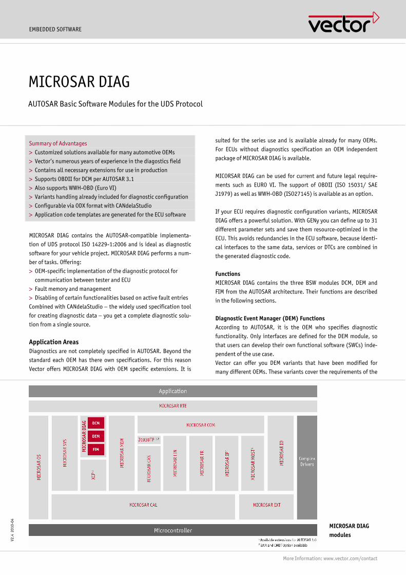
MICROSAR DIAG modules
EMBEDDED SOFTWARE
More Information: www.vector.com/contact
V2.4
201
0-04
Summary of Advantages
> Customized solutions available for many automotive OEMs
> Vector�s numerous years of experience in the diagostics field
> Contains all necessary extensions for use in production
> Supports OBDII for DCM per AUTOSAR 3.1
> Also supports WWH-OBD (Euro VI)
> Variants handling already included for diagnostic configuration
> Configurable via ODX format with CANdelaStudio
> Application code templates are generated for the ECU software
MICROSAR DIAG contains the AUTOSAR-compatible implementa-
tion of UDS protocol ISO 14229-1:2006 and is ideal as diagnostic
software for your vehicle project. MICROSAR DIAG performs a num-
ber of tasks. Offering:
> OEM-specific implementation of the diagnostic protocol for
communication between tester and ECU
> Fault memory and management
> Disabling of certain functionalities based on active fault entries
Combined with CANdelaStudio − the widely used specification tool
for creating diagnostic data − you get a complete diagnostic solu-
tion from a single source.
Application Areas Diagnostics are not completely specified in AUTOSAR. Beyond the
standard each OEM has there own specifications. For this reason
Vector offers MICROSAR DIAG with OEM specific extensions. It is
suited for the series use and is available already for many OEMs.
For ECUs without diagnostics specification an OEM independent
package of MICROSAR DIAG is available.
MICORSAR DIAG can be used for current and future legal require-
ments such as EURO VI. The support of OBDII (ISO 15031/ SAE
J1979) as well as WWH-OBD (ISO27145) is available as an option.
If your ECU requires diagnostic configuration variants, MICROSAR
DIAG offers a powerful solution. With GENy you can define up to 31
different parameter sets and save them resource-optimized in the
ECU. This avoids redundancies in the ECU software, because identi-
cal interfaces to the same data, services or DTCs are combined in
the generated diagnostic code.
Functions MICROSAR DIAG contains the three BSW modules DCM, DEM and
FIM from the AUTOSAR architecture. Their functions are described
in the following sections.
Diagnostic Event Manager (DEM) Functions According to AUTOSAR, it is the OEM who specifies diagnostic
functionality. Only interfaces are defined for the DEM module, so
that users can develop their own functional software (SWCs) inde-
pendent of the use case.
Vector can offer you DEM variants that have been modified for
many different OEMs. These variants cover the requirements of the
MICROSAR DIAG AUTOSAR Basic Software Modules for the UDS Protocol
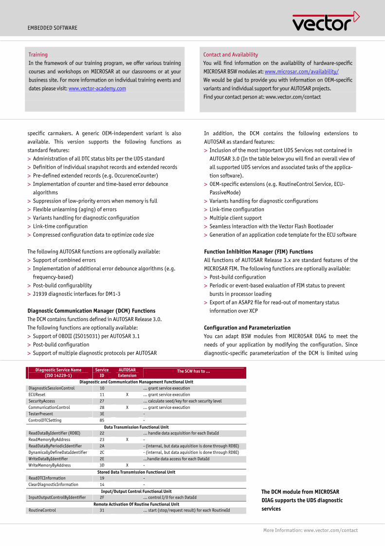
EMBEDDED SOFTWARE
More Information: www.vector.com/contact
specific carmakers. A generic OEM-independent variant is also
available. This version supports the following functions as
standard features:
> Administration of all DTC status bits per the UDS standard
> Definition of individual snapshot records and extended records
> Pre-defined extended records (e.g. OccurenceCounter)
> Implementation of counter and time-based error debounce
algorithms
> Suppression of low-priority errors when memory is full
> Flexible unlearning (aging) of errors
> Variants handling for diagnostic configuration
> Link-time configuration
> Compressed configuration data to optimize code size
The following AUTOSAR functions are optionally available:
> Support of combined errors
> Implementation of additional error debounce algorithms (e.g.
frequency-based)
> Post-build configurability
> J1939 diagnostic interfaces for DM1-3
Diagnostic Communication Manager (DCM) Functions The DCM contains functions defined in AUTOSAR Release 3.0.
The following functions are optionally available:
> Support of OBDII (ISO15031) per AUTOSAR 3.1
> Post-build configuration
> Support of multiple diagnostic protocols per AUTOSAR
In addition, the DCM contains the following extensions to
AUTOSAR as standard features:
> Inclusion of the most important UDS Services not contained in
AUTOSAR 3.0 (In the table below you will find an overall view of
all supported UDS services and associated tasks of the applica-
tion software).
> OEM-specific extensions (e.g. RoutineControl Service, ECU-
PassiveMode)
> Variants handling for diagnostic configurations
> Link-time configuration
> Multiple client support
> Seamless interaction with the Vector Flash Bootloader
> Generation of an application code template for the ECU software
Function Inhibition Manager (FIM) Functions All functions of AUTOSAR Release 3.x are standard features of the
MICROSAR FIM. The following functions are optionally available:
> Post-build configuration
> Periodic or event-based evaluation of FIM status to prevent
bursts in processor loading
> Export of an ASAP2 file for read-out of momentary status
information over XCP
Configuration and Parameterization You can adapt BSW modules from MICROSAR DIAG to meet the
needs of your application by modifying the configuration. Since
diagnostic-specific parameterization of the DCM is limited using
The DCM module from MICROSAR DIAG supports the UDS diagnostic services
Diagnostic Service Name (ISO 14229-1)
Service ID
AUTOSAR Extension
The SCW has to �
Diagnostic and Communication Management Functional Unit DiagnosticSessionControl 10 � grant service execution ECUReset 11 X � grant service execution SecurityAccess 27 � calculate seed/key for each security level CommunicationControl 28 X � grant service execution TesterPresent 3E - ControlDTCSetting 85 -
Data Transmission Functional Unit ReadDataByIdentifier (RDBI) 22 � handle data acquisition for each DataId ReadMemoryByAddress 23 X - ReadDataByPeriodicIdentifier 2A - (internal, but data aquisition is done through RDBI) DynamicallyDefineDataIdentifier 2C - (internal, but data aquisition is done through RDBI) WriteDataByIdentifier 2E �handle data access for each DataId WriteMemoryByAddress 3D X -
Stored Data Transmission Functional Unit ReadDTCInformation 19 - ClearDiagnosticInformation 14 -
Input/Output Control Functional Unit InputOutputControlByIdentifier 2F � control I/O for each DataId
Remote Activation Of Routine Functional Unit RoutineControl 31 � start (stop/request result) for each RoutineId
Contact and Availability
You will find information on the availability of hardware-specific
MICROSAR BSW modules at: www.microsar.com/availability/
We would be glad to provide you with information on OEM-specific
variants and individual support for your AUTOSAR projects.
Find your contact person at: www.vector.com/contact
Training
In the framework of our training program, we offer various training
courses and workshops on MICROSAR at our classrooms or at your
business site. For more information on individual training events and
dates please visit: www.vector-academy.com
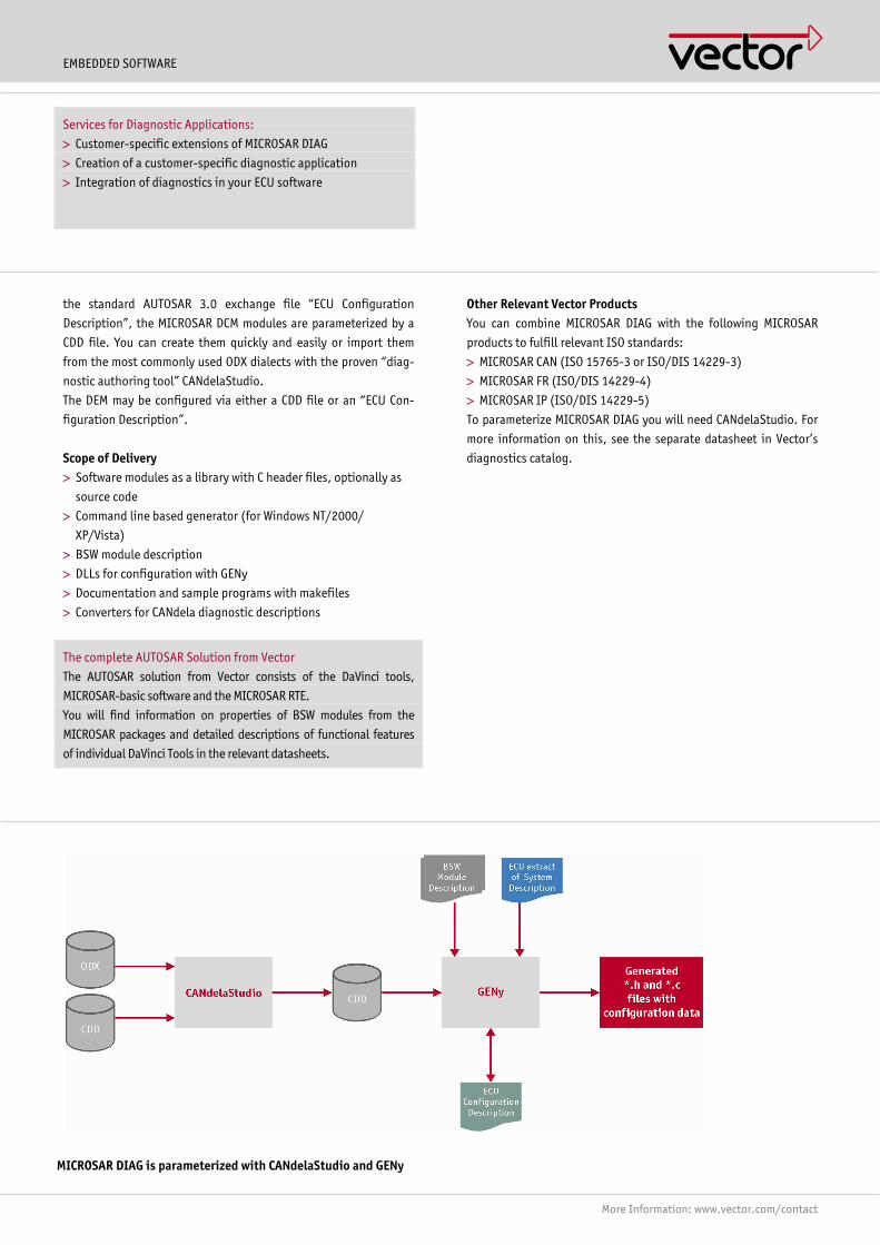
EMBEDDED SOFTWARE
More Information: www.vector.com/contact
the standard AUTOSAR 3.0 exchange file �ECU Configuration
Description�, the MICROSAR DCM modules are parameterized by a
CDD file. You can create them quickly and easily or import them
from the most commonly used ODX dialects with the proven �diag-
nostic authoring tool� CANdelaStudio.
The DEM may be configured via either a CDD file or an �ECU Con-
figuration Description�.
Scope of Delivery > Software modules as a library with C header files, optionally as
source code
> Command line based generator (for Windows NT/2000/
XP/Vista)
> BSW module description
> DLLs for configuration with GENy
> Documentation and sample programs with makefiles
> Converters for CANdela diagnostic descriptions
The complete AUTOSAR Solution from Vector
The AUTOSAR solution from Vector consists of the DaVinci tools,
MICROSAR-basic software and the MICROSAR RTE.
You will find information on properties of BSW modules from the
MICROSAR packages and detailed descriptions of functional features
of individual DaVinci Tools in the relevant datasheets.
Other Relevant Vector Products You can combine MICROSAR DIAG with the following MICROSAR
products to fulfill relevant ISO standards:
> MICROSAR CAN (ISO 15765-3 or ISO/DIS 14229-3)
> MICROSAR FR (ISO/DIS 14229-4)
> MICROSAR IP (ISO/DIS 14229-5)
To parameterize MICROSAR DIAG you will need CANdelaStudio. For
more information on this, see the separate datasheet in Vector�s
diagnostics catalog.
Services for Diagnostic Applications:
> Customer-specific extensions of MICROSAR DIAG
> Creation of a customer-specific diagnostic application
> Integration of diagnostics in your ECU software
MICROSAR DIAG is parameterized with CANdelaStudio and GENy

EMBEDDED SOFTWARE
More Information: www.vector.com/contact
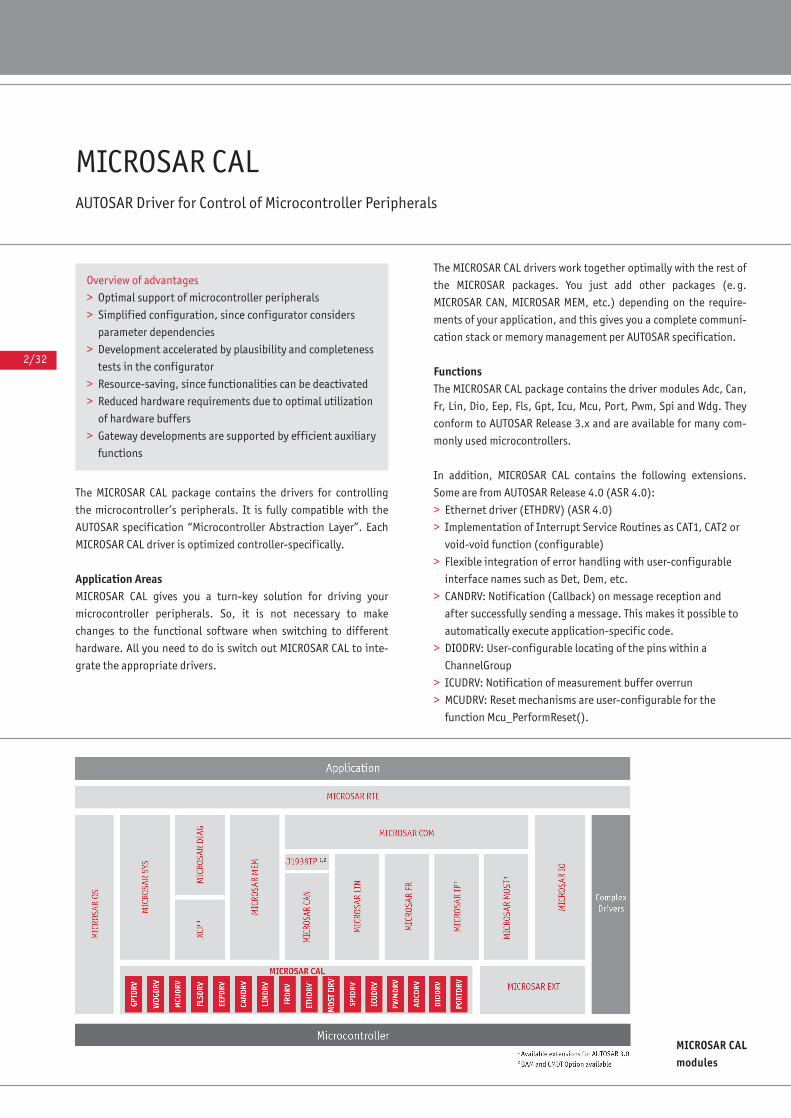
2/32
MICROSAR CALAUTOSAR Driver for Control of Microcontroller Peripherals
The MICROSAR CAL package contains the drivers for controlling
the microcontroller’s peripherals. It is fully compatible with the
AUTOSAR specification “Microcontroller Abstraction Layer”. Each
MICROSAR CAL driver is optimized controller-specifically.
Application AreasMICROSAR CAL gives you a turn-key solution for driving your
microcontroller peripherals. So, it is not necessary to make
changes to the functional software when switching to different
hardware. All you need to do is switch out MICROSAR CAL to inte-
grate the appropriate drivers.
The MICROSAR CAL drivers work together optimally with the rest of
the MICROSAR packages. You just add other packages (e.g.
MICROSAR CAN, MICROSAR MEM, etc.) depending on the require-
ments of your application, and this gives you a complete communi-
cation stack or memory management per AUTOSAR specification.
FunctionsThe MICROSAR CAL package contains the driver modules Adc, Can,
Fr, Lin, Dio, Eep, Fls, Gpt, Icu, Mcu, Port, Pwm, Spi and Wdg. They
conform to AUTOSAR Release 3.x and are available for many com-
monly used microcontrollers.
In addition, MICROSAR CAL contains the following extensions.
Some are from AUTOSAR Release 4.0 (ASR 4.0):
> Ethernet driver (ETHDRV) (ASR 4.0)
> Implementation of Interrupt Service Routines as CAT1, CAT2 or
void-void function (configurable)
> Flexible integration of error handling with user-configurable
interface names such as Det, Dem, etc.
> CANDRV: Notification (Callback) on message reception and
after successfully sending a message. This makes it possible to
automatically execute application-specific code.
> DIODRV: User-configurable locating of the pins within a
ChannelGroup
> ICUDRV: Notification of measurement buffer overrun
> MCUDRV: Reset mechanisms are user-configurable for the
function Mcu_PerformReset().
MICROSAR CALmodules
Overview of advantages
> Optimal support of microcontroller peripherals
> Simplified configuration, since configurator considers
parameter dependencies
> Development accelerated by plausibility and completeness
tests in the configurator
> Resource-saving, since functionalities can be deactivated
> Reduced hardware requirements due to optimal utilization
of hardware buffers
> Gateway developments are supported by efficient auxiliary
functions

2/33
AUTOSAR
The following functionalities are available options:
> FRDRV: Bus self-diagnostics. If the FlexRay controller detects
an error, it sets a status bit that is polled by the FlexRay driver
(FRDRV).
> FRDRV: The FlexRay configuration can be read out by a
diagnostic command.
> CANDRV: Extended filter options for multiple basic CAN objects
> CANDRV: Rx queue for reducing interrupt execution time while
receiving messages
Scope of Delivery> Software modules as library with C header files, optionally as
source code
> Command line based generator (for Windows NT/2000/XP/
Vista)
> BSW module description
> DLLs for configuration with GENy
> Description files for DaVinci Configurator Pro
> Documentation and sample programs with makefiles
Additional Services> Integration of drivers by third-party producers, e.g. semicon-
ductor manufacturers, in DaVinci Configurator Pro. This lets the
user configure the entire ECU software with a single tool,
seamlessly and quickly.
> In the framework of project work, Vector would be glad to
create a low-level MOST driver for your specific hardware to
interface it to SMSC NetServices. ◆
Contact and AvailabilityFor information on the availability of hardware-specific MICROSAR BSW modules go to: www.microsar.com/availability/ We would be glad to provide you with information on OEM-specific versions and individual support for your AUTOSARprojects. Find your contact person at: www.vector.com/contact
Training
In the framework of our training program we can offer vari-
ous training courses and workshops on MICROSAR at our
classrooms or at your business site.
For more information on individual training events and dates
please visit: www.vector-academy.com
Configuration of the ADCDRVwith DaVinci Configurator Pro
The complete AUTOSAR solution from Vector
The AUTOSAR solution from Vector consists of the DaVinci
tools, MICROSAR basic software and MICROSAR RTE.
You will find information on properties of BSW modules from
the MICROSAR packages as well as detailed descriptions of
functional features of the DaVinci Tools in the particular
datasheets.
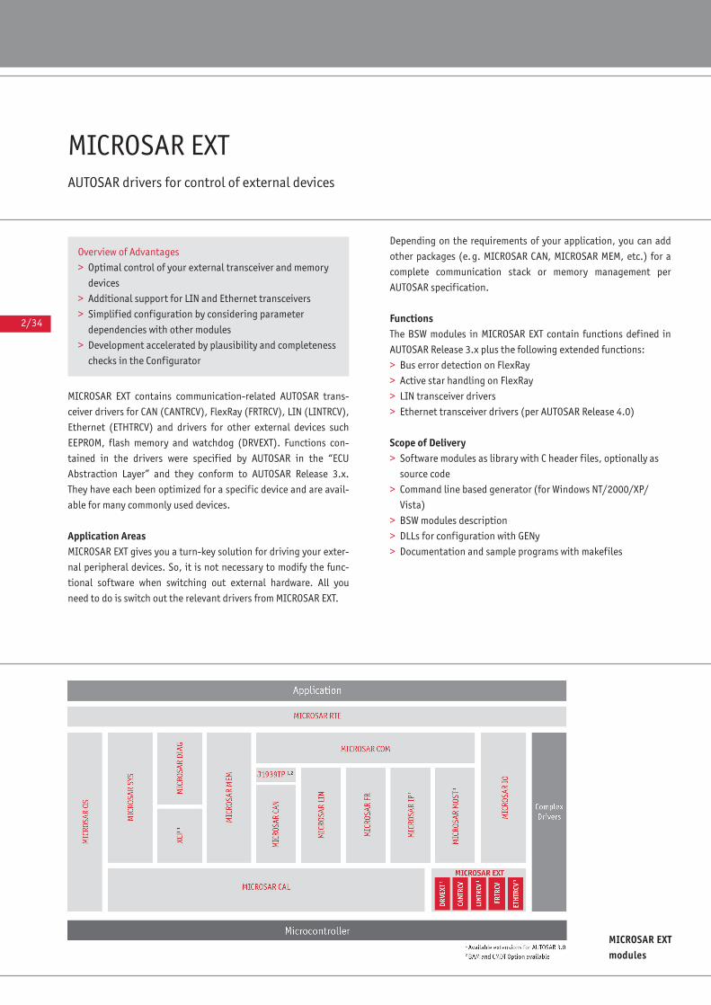
2/34
MICROSAR EXTAUTOSAR drivers for control of external devices
MICROSAR EXT contains communication-related AUTOSAR trans-
ceiver drivers for CAN (CANTRCV), FlexRay (FRTRCV), LIN (LINTRCV),
Ethernet (ETHTRCV) and drivers for other external devices such
EEPROM, flash memory and watchdog (DRVEXT). Functions con-
tained in the drivers were specified by AUTOSAR in the “ECU
Abstraction Layer” and they conform to AUTOSAR Release 3.x.
They have each been optimized for a specific device and are avail-
able for many commonly used devices.
Application AreasMICROSAR EXT gives you a turn-key solution for driving your exter-
nal peripheral devices. So, it is not necessary to modify the func-
tional software when switching out external hardware. All you
need to do is switch out the relevant drivers from MICROSAR EXT.
Depending on the requirements of your application, you can add
other packages (e.g. MICROSAR CAN, MICROSAR MEM, etc.) for a
complete communication stack or memory management per
AUTOSAR specification.
FunctionsThe BSW modules in MICROSAR EXT contain functions defined in
AUTOSAR Release 3.x plus the following extended functions:
> Bus error detection on FlexRay
> Active star handling on FlexRay
> LIN transceiver drivers
> Ethernet transceiver drivers (per AUTOSAR Release 4.0)
Scope of Delivery> Software modules as library with C header files, optionally as
source code
> Command line based generator (for Windows NT/2000/XP/
Vista)
> BSW modules description
> DLLs for configuration with GENy
> Documentation and sample programs with makefiles
MICROSAR EXTmodules
Overview of Advantages
> Optimal control of your external transceiver and memory
devices
> Additional support for LIN and Ethernet transceivers
> Simplified configuration by considering parameter
dependencies with other modules
> Development accelerated by plausibility and completeness
checks in the Configurator
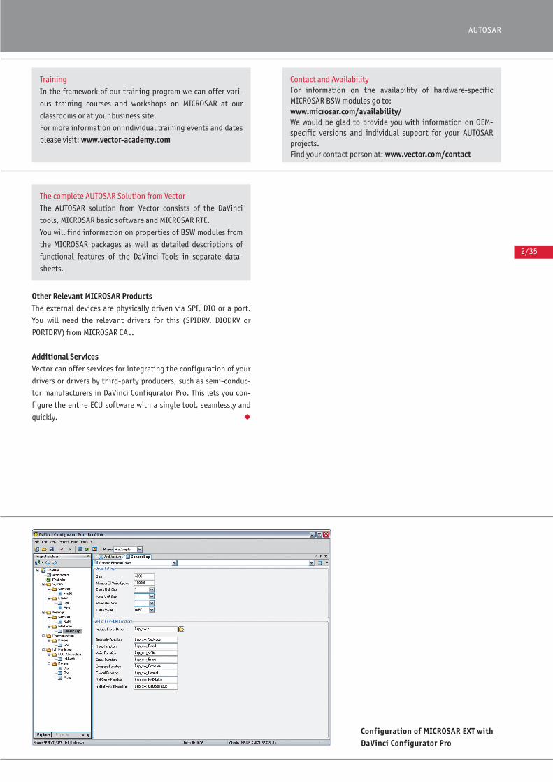
2/35
AUTOSAR
#
Other Relevant MICROSAR ProductsThe external devices are physically driven via SPI, DIO or a port.
You will need the relevant drivers for this (SPIDRV, DIODRV or
PORTDRV) from MICROSAR CAL.
Additional ServicesVector can offer services for integrating the configuration of your
drivers or drivers by third-party producers, such as semi-conduc-
tor manufacturers in DaVinci Configurator Pro. This lets you con-
figure the entire ECU software with a single tool, seamlessly and
quickly. ◆
Configuration of MICROSAR EXT withDaVinci Configurator Pro
Training
In the framework of our training program we can offer vari-
ous training courses and workshops on MICROSAR at our
classrooms or at your business site.
For more information on individual training events and dates
please visit: www.vector-academy.com
Contact and AvailabilityFor information on the availability of hardware-specific MICROSAR BSW modules go to: www.microsar.com/availability/ We would be glad to provide you with information on OEM-specific versions and individual support for your AUTOSARprojects.Find your contact person at: www.vector.com/contact
The complete AUTOSAR Solution from Vector
The AUTOSAR solution from Vector consists of the DaVinci
tools, MICROSAR basic software and MICROSAR RTE.
You will find information on properties of BSW modules from
the MICROSAR packages as well as detailed descriptions of
functional features of the DaVinci Tools in separate data-
sheets.
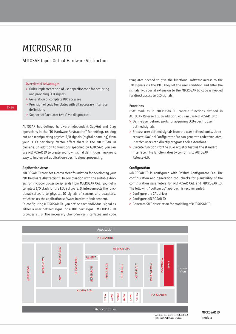
2/36
MICROSAR IO AUTOSAR Input-Output Hardware Abstraction
AUTOSAR has defined hardware-independent Set/Get and Diag
operations in the “IO Hardware Abstraction” for setting, reading
out and manipulating physical I/O signals (digital or analog) from
your ECU’s periphery. Vector offers them in the MICROSAR IO
package. In addition to functions specified by AUTOSAR, you can
use MICROSAR IO to create your own signal definitions, making it
easy to implement application-specific signal processing.
Application AreasMICROSAR IO provides a convenient foundation for developing your
“IO Hardware Abstraction”. In combination with the suitable driv-
ers for microcontroller peripherals from MICROSAR CAL, you get a
complete I/O stack for the ECU software. It interconnects the func-
tional software to physical IO signals of sensors and actuators,
which makes the application software hardware-independent.
In configuring MICROSAR IO, you define each individual signal as
either a user defined signal or a DIO port signal. MICROSAR IO
provides all of the necessary Client/Server interfaces and code
templates needed to give the functional software access to the
I/O signals via the RTE. They let the user condition and filter the
signals. No special extension to the MICROSAR IO code is needed
for direct access to DIO signals.
Functions BSW modules in MICROSAR IO contain functions defined in
AUTOSAR Release 3.x. In addition, you can use MICROSAR IO to:
> Define user defined ports for acquiring ECU-specific user
defined signals.
> Process user defined signals from the user defined ports. Upon
request, DaVinci Configurator Pro can generate code templates,
in which users can directly program their extensions.
> Execute functions for the DCM actuator test via the standard
interface. This function already conforms to AUTOSAR
Release 4.0.
Configuration MICROSAR IO is configured with DaVinci Configurator Pro. The
configuration and generation tool checks for plausibility of the
configuration parameters for MICROSAR CAL and MICROSAR IO.
The following “bottom up” approach is recommended:
> Configure the CAL driver
> Configure MICROSAR IO
> Generate SWC description for modeling of MICROSAR IO
MICROSAR IOmodule
Overview of Advantages
> Quick implementation of user-specific code for acquiring
and providing ECU signals
> Generation of complete DIO accesses
> Provision of code templates with all necessary interface
definitions
> Support of “actuator tests” via diagnostics
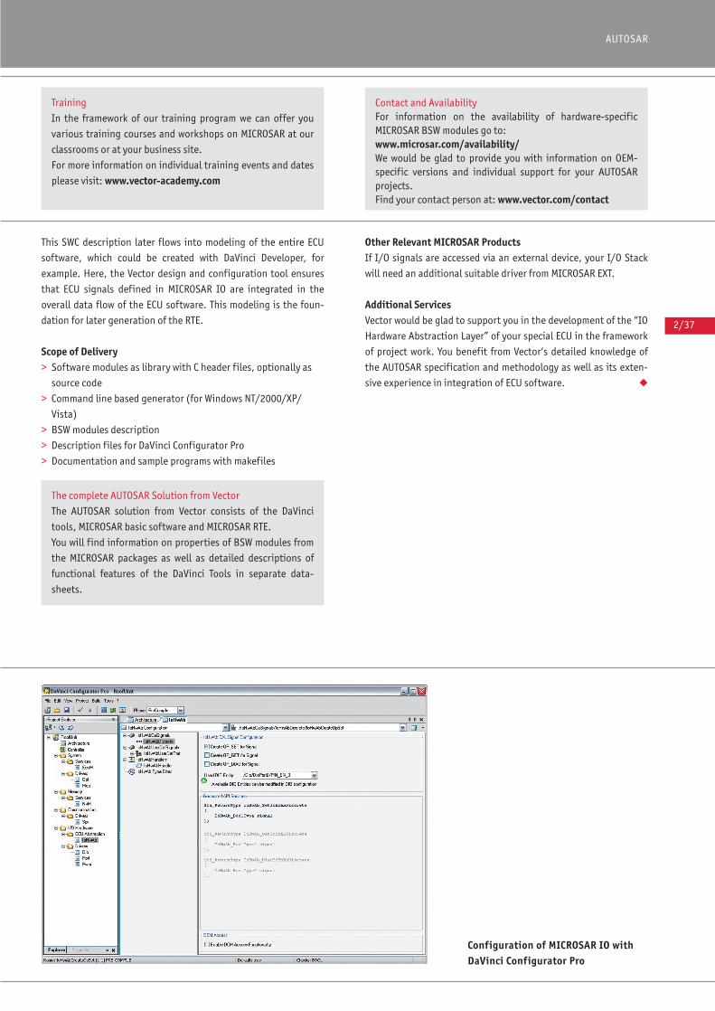
2/37
AUTOSAR
This SWC description later flows into modeling of the entire ECU
software, which could be created with DaVinci Developer, for
example. Here, the Vector design and configuration tool ensures
that ECU signals defined in MICROSAR IO are integrated in the
overall data flow of the ECU software. This modeling is the foun-
dation for later generation of the RTE.
Scope of Delivery> Software modules as library with C header files, optionally as
source code
> Command line based generator (for Windows NT/2000/XP/
Vista)
> BSW modules description
> Description files for DaVinci Configurator Pro
> Documentation and sample programs with makefiles
Other Relevant MICROSAR ProductsIf I/O signals are accessed via an external device, your I/O Stack
will need an additional suitable driver from MICROSAR EXT.
Additional ServicesVector would be glad to support you in the development of the “IO
Hardware Abstraction Layer” of your special ECU in the framework
of project work. You benefit from Vector‘s detailed knowledge of
the AUTOSAR specification and methodology as well as its exten-
sive experience in integration of ECU software. ◆
Configuration of MICROSAR IO withDaVinci Configurator Pro
Training
In the framework of our training program we can offer you
various training courses and workshops on MICROSAR at our
classrooms or at your business site.
For more information on individual training events and dates
please visit: www.vector-academy.com
Contact and AvailabilityFor information on the availability of hardware-specific MICROSAR BSW modules go to: www.microsar.com/availability/ We would be glad to provide you with information on OEM-specific versions and individual support for your AUTOSARprojects.Find your contact person at: www.vector.com/contact
The complete AUTOSAR Solution from Vector
The AUTOSAR solution from Vector consists of the DaVinci
tools, MICROSAR basic software and MICROSAR RTE.
You will find information on properties of BSW modules from
the MICROSAR packages as well as detailed descriptions of
functional features of the DaVinci Tools in separate data-
sheets.
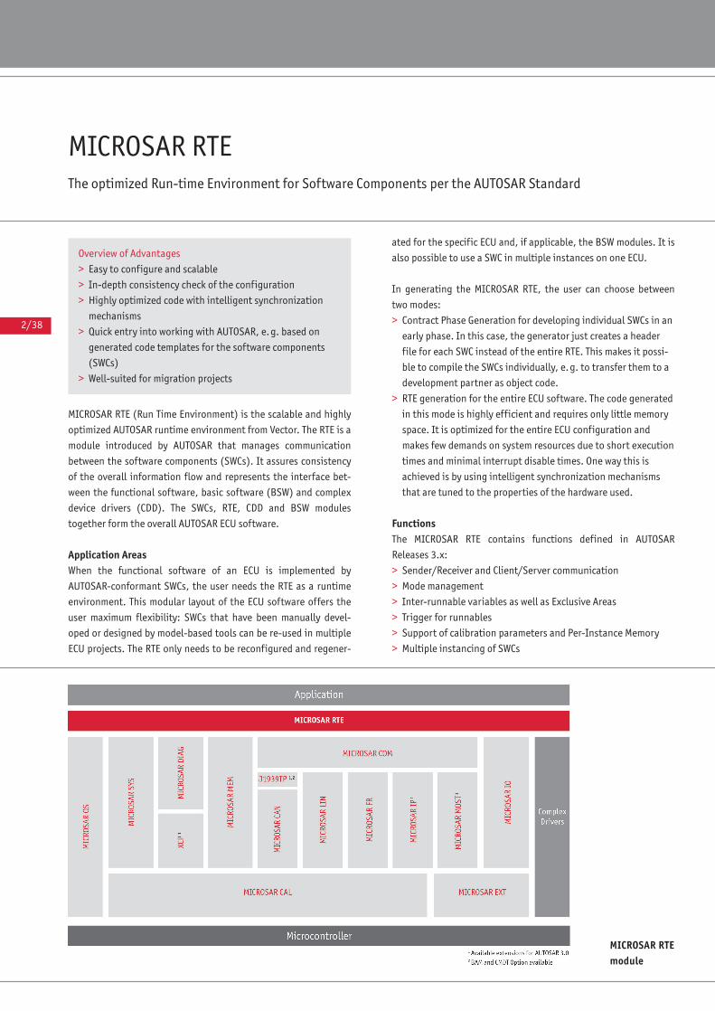
2/38
MICROSAR RTE The optimized Run-time Environment for Software Components per the AUTOSAR Standard
MICROSAR RTE (Run Time Environment) is the scalable and highly
optimized AUTOSAR runtime environment from Vector. The RTE is a
module introduced by AUTOSAR that manages communication
between the software components (SWCs). It assures consistency
of the overall information flow and represents the interface bet-
ween the functional software, basic software (BSW) and complex
device drivers (CDD). The SWCs, RTE, CDD and BSW modules
together form the overall AUTOSAR ECU software.
Application AreasWhen the functional software of an ECU is implemented by
AUTOSAR-conformant SWCs, the user needs the RTE as a runtime
environment. This modular layout of the ECU software offers the
user maximum flexibility: SWCs that have been manually devel-
oped or designed by model-based tools can be re-used in multiple
ECU projects. The RTE only needs to be reconfigured and regener-
ated for the specific ECU and, if applicable, the BSW modules. It is
also possible to use a SWC in multiple instances on one ECU.
In generating the MICROSAR RTE, the user can choose between
two modes:
> Contract Phase Generation for developing individual SWCs in an
early phase. In this case, the generator just creates a header
file for each SWC instead of the entire RTE. This makes it possi-
ble to compile the SWCs individually, e.g. to transfer them to a
development partner as object code.
> RTE generation for the entire ECU software. The code generated
in this mode is highly efficient and requires only little memory
space. It is optimized for the entire ECU configuration and
makes few demands on system resources due to short execution
times and minimal interrupt disable times. One way this is
achieved is by using intelligent synchronization mechanisms
that are tuned to the properties of the hardware used.
Functions The MICROSAR RTE contains functions defined in AUTOSAR
Releases 3.x:
> Sender/Receiver and Client/Server communication
> Mode management
> Inter-runnable variables as well as Exclusive Areas
> Trigger for runnables
> Support of calibration parameters and Per-Instance Memory
> Multiple instancing of SWCs
MICROSAR RTEmodule
Overview of Advantages
> Easy to configure and scalable
> In-depth consistency check of the configuration
> Highly optimized code with intelligent synchronization
mechanisms
> Quick entry into working with AUTOSAR, e.g. based on
generated code templates for the software components
(SWCs)
> Well-suited for migration projects
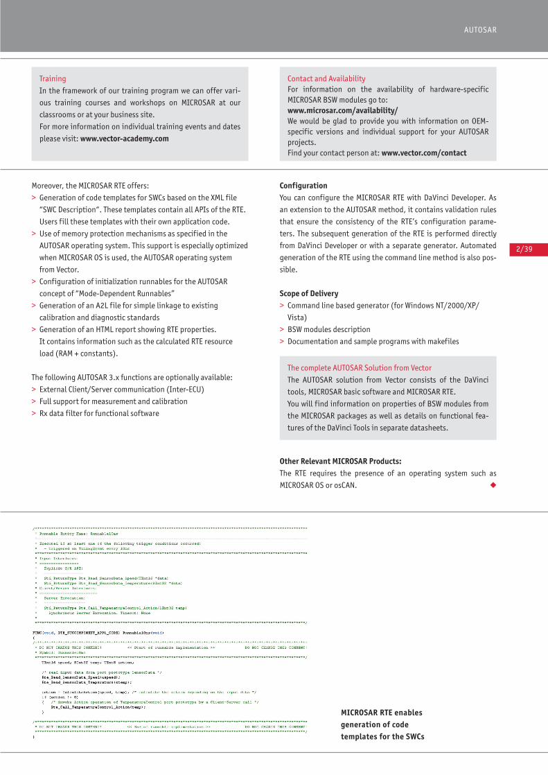
2/39
AUTOSAR
Moreover, the MICROSAR RTE offers:
> Generation of code templates for SWCs based on the XML file
“SWC Description“. These templates contain all APIs of the RTE.
Users fill these templates with their own application code.
> Use of memory protection mechanisms as specified in the
AUTOSAR operating system. This support is especially optimized
when MICROSAR OS is used, the AUTOSAR operating system
from Vector.
> Configuration of initialization runnables for the AUTOSAR
concept of “Mode-Dependent Runnables”
> Generation of an A2L file for simple linkage to existing
calibration and diagnostic standards
> Generation of an HTML report showing RTE properties.
It contains information such as the calculated RTE resource
load (RAM + constants).
The following AUTOSAR 3.x functions are optionally available:
> External Client/Server communication (Inter-ECU)
> Full support for measurement and calibration
> Rx data filter for functional software
Configuration You can configure the MICROSAR RTE with DaVinci Developer. As
an extension to the AUTOSAR method, it contains validation rules
that ensure the consistency of the RTE’s configuration parame-
ters. The subsequent generation of the RTE is performed directly
from DaVinci Developer or with a separate generator. Automated
generation of the RTE using the command line method is also pos-
sible.
Scope of Delivery> Command line based generator (for Windows NT/2000/XP/
Vista)
> BSW modules description
> Documentation and sample programs with makefiles
Other Relevant MICROSAR Products:The RTE requires the presence of an operating system such as
MICROSAR OS or osCAN. ◆
MICROSAR RTE enablesgeneration of codetemplates for the SWCs
Training
In the framework of our training program we can offer vari-
ous training courses and workshops on MICROSAR at our
classrooms or at your business site.
For more information on individual training events and dates
please visit: www.vector-academy.com
Contact and AvailabilityFor information on the availability of hardware-specific MICROSAR BSW modules go to: www.microsar.com/availability/ We would be glad to provide you with information on OEM-specific versions and individual support for your AUTOSARprojects.Find your contact person at: www.vector.com/contact
The complete AUTOSAR Solution from Vector
The AUTOSAR solution from Vector consists of the DaVinci
tools, MICROSAR basic software and MICROSAR RTE.
You will find information on properties of BSW modules from
the MICROSAR packages as well as details on functional fea-
tures of the DaVinci Tools in separate datasheets.
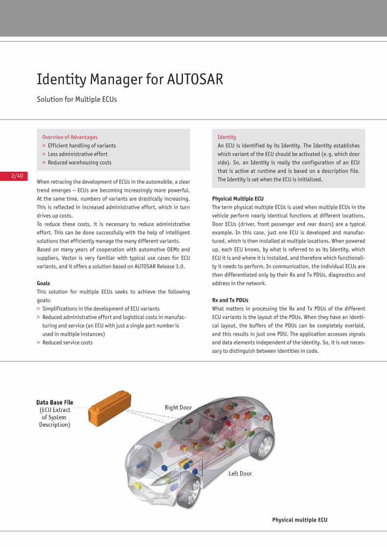
2/40
Identity Manager for AUTOSARSolution for Multiple ECUs
When retracing the development of ECUs in the automobile, a clear
trend emerges – ECUs are becoming increasingly more powerful.
At the same time, numbers of variants are drastically increasing.
This is reflected in increased administrative effort, which in turn
drives up costs.
To reduce these costs, it is necessary to reduce administrative
effort. This can be done successfully with the help of intelligent
solutions that efficiently manage the many different variants.
Based on many years of cooperation with automotive OEMs and
suppliers, Vector is very familiar with typical use cases for ECU
variants, and it offers a solution based on AUTOSAR Release 3.0.
GoalsThis solution for multiple ECUs seeks to achieve the following
goals:
> Simplifications in the development of ECU variants
> Reduced administrative effort and logistical costs in manufac-
turing and service (an ECU with just a single part number is
used in multiple instances)
> Reduced service costs
Physical Multiple ECUThe term physical multiple ECUs is used when multiple ECUs in the
vehicle perform nearly identical functions at different locations.
Door ECUs (driver, front passenger and rear doors) are a typical
example. In this case, just one ECU is developed and manufac-
tured, which is then installed at multiple locations. When powered
up, each ECU knows, by what is referred to as its Identity, which
ECU it is and where it is installed, and therefore which functionali-
ty it needs to perform. In communication, the individual ECUs are
then differentiated only by their Rx and Tx PDUs, diagnostics and
address in the network.
Rx and Tx PDUsWhat matters in processing the Rx and Tx PDUs of the different
ECU variants is the layout of the PDUs. When they have an identi-
cal layout, the buffers of the PDUs can be completely overlaid,
and this results in just one PDU. The application accesses signals
and data elements independent of the identity. So, it is not neces-
sary to distinguish between identities in code.
Physical multiple ECU
Overview of Advantages
> Efficient handling of variants
> Less administrative effort
> Reduced warehousing costs
Identity
An ECU is identified by its Identity. The Identity establishes
which variant of the ECU should be activated (e.g. which door
side). So, an Identity is really the configuration of an ECU
that is active at runtime and is based on a description file.
The Identity is set when the ECU is initialized.
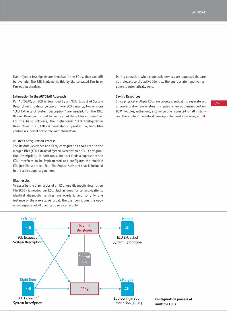
2/41
AUTOSAR
Even if just a few signals are identical in the PDUs, they can still
be overlaid. The RTE implements this by the so-called Fan-in or
Fan-out mechanism.
Integration in the AUTOSAR ApproachPer AUTOSAR, an ECU is described by an “ECU Extract of System
Description”. To describe two or more ECU variants, two or more
“ECU Extracts of System Description” are needed. For the RTE,
DaVinci Developer is used to merge all of these files into one file.
For the basic software, the higher-level “ECU Configuration
Description” file (ECUC) is generated in parallel. So, both files
contain a superset of the relevant information.
Trusted Configuration ProcessThe DaVinci Developer and GENy configuration tools read-in the
merged files (ECU Extract of System Description or ECU Configura-
tion Description). In both tools, the user finds a superset of the
ECU interfaces to be implemented and configures the multiple
ECU just like a normal ECU. The Project Assistant that is included
in the tools supports you here.
DiagnosticsTo describe the diagnostics of an ECU, one diagnostic description
file (CDD) is needed per ECU. Just as done for communications,
identical diagnostic services are overlaid, and so only one
instance of them exists. As usual, the user configures the opti-
mized superset of all diagnostic services in GENy.
During operation, when diagnostic services are requested that are
not relevant to the active Identity, the appropriate negative res-
ponse is automatically sent.
Saving ResourcesSince physical multiple ECUs are largely identical, no separate set
of configuration parameters is created when optimizing certain
BSW modules, rather only a common one is created for all instan-
ces. This applies to identical messages, diagnostic services, etc. ◆
Configuration process ofmultiple ECUs
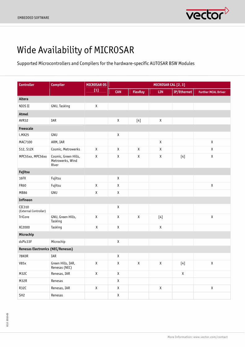
EMBEDDED SOFTWARE
More Information: www.vector.com/contact
V2.0
201
0-05
MICROSAR CAL [2, 3] Controller Compiler MICROSAR OS[1] CAN FlexRay LIN IP/Ethernet Further MCAL Driver
Altera
NIOS II GNU, Tasking X
Atmel
AVR32 IAR X [4] X
Freescale
i.MX25 GNU X
MAC7100 ARM, IAR X X
S12, S12X Cosmic, Metrowerks X X X X X
MPC55xx, MPC56xx Cosmic, Green Hills, Metrowerks, Wind River
X X X X [4] X
Fujitsu
16FX Fujitsu X
FR60 Fujitsu X X X
MB86 GNU X X
Infineon
CIC310 (External Controller)
X
TriCore GNU, Green Hills, Tasking
X X X [4] X
XC2000 Tasking X X X
Microchip
dsPic33F Microchip X
Renesas Electronics (NEC/Renesas)
78K0R IAR X
V85x Green Hills, IAR, Renesas (NEC)
X X X X [4] X
M32C Renesas, IAR X X X
M32R Renesas X
R32C Renesas, IAR X X X X
SH2 Renesas X
Wide Availability of MICROSAR Supported Microcontrollers and Compilers for the hardware-specific AUTOSAR BSW Modules
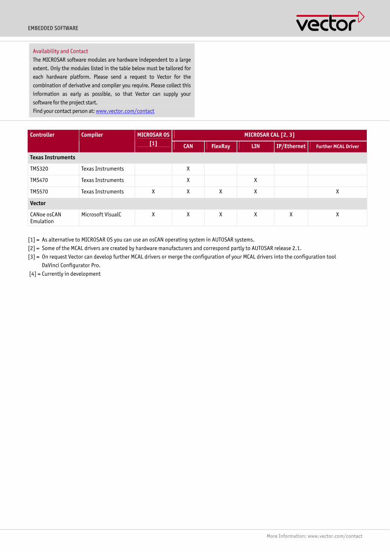
EMBEDDED SOFTWARE
More Information: www.vector.com/contact
MICROSAR CAL [2, 3] Controller Compiler MICROSAR OS[1] CAN FlexRay LIN IP/Ethernet Further MCAL Driver
Texas Instruments
TMS320 Texas Instruments X
TMS470 Texas Instruments X X
TMS570 Texas Instruments X X X X X
Vector
CANoe osCAN Emulation
Microsoft VisualC X X X X X X
[1] = As alternative to MICROSAR OS you can use an osCAN operating system in AUTOSAR systems.
[2] = Some of the MCAL drivers are created by hardware manufacturers and correspond partly to AUTOSAR release 2.1.
[3] = On request Vector can develop further MCAL drivers or merge the configuration of your MCAL drivers into the configuration tool
DaVinci Configurator Pro.
[4] = Currently in development
Availability and Contact
The MICROSAR software modules are hardware independent to a large
extent. Only the modules listed in the table below must be tailored for
each hardware platform. Please send a request to Vector for the
combination of derivative and compiler you require. Please collect this
information as early as possible, so that Vector can supply your
software for the project start.
Find your contact person at: www.vector.com/contact
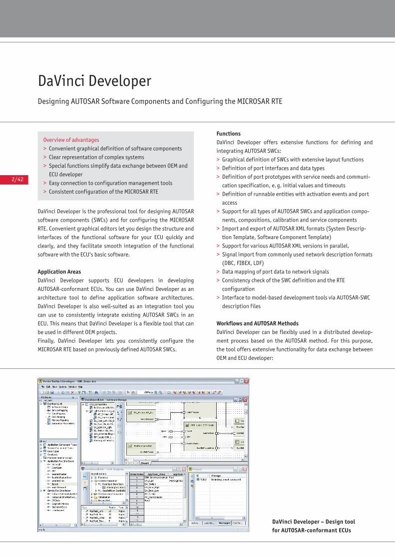
2/42
DaVinci Developer Designing AUTOSAR Software Components and Configuring the MICROSAR RTE
DaVinci Developer is the professional tool for designing AUTOSAR
software components (SWCs) and for configuring the MICROSAR
RTE. Convenient graphical editors let you design the structure and
interfaces of the functional software for your ECU quickly and
clearly, and they facilitate smooth integration of the functional
software with the ECU‘s basic software.
Application AreasDaVinci Developer supports ECU developers in developing
AUTOSAR-conformant ECUs. You can use DaVinci Developer as an
architecture tool to define application software architectures.
DaVinci Developer is also well-suited as an integration tool you
can use to consistently integrate existing AUTOSAR SWCs in an
ECU. This means that DaVinci Developer is a flexible tool that can
be used in different OEM projects.
Finally, DaVinci Developer lets you consistently configure the
MICROSAR RTE based on previously defined AUTOSAR SWCs.
FunctionsDaVinci Developer offers extensive functions for defining and
integrating AUTOSAR SWCs:
> Graphical definition of SWCs with extensive layout functions
> Definition of port interfaces and data types
> Definition of port prototypes with service needs and communi-
cation specification, e.g. initial values and timeouts
> Definition of runnable entities with activation events and port
access
> Support for all types of AUTOSAR SWCs and application compo-
nents, compositions, calibration and service components
> Import and export of AUTOSAR XML formats (System Descrip-
tion Template, Software Component Template)
> Support for various AUTOSAR XML versions in parallel.
> Signal import from commonly used network description formats
(DBC, FIBEX, LDF)
> Data mapping of port data to network signals
> Consistency check of the SWC definition and the RTE
configuration
> Interface to model-based development tools via AUTOSAR-SWC
description files
Workflows and AUTOSAR MethodsDaVinci Developer can be flexibly used in a distributed develop-
ment process based on the AUTOSAR method. For this purpose,
the tool offers extensive functionality for data exchange between
OEM and ECU developer:
Overview of advantages
> Convenient graphical definition of software components
> Clear representation of complex systems
> Special functions simplify data exchange between OEM and
ECU developer
> Easy connection to configuration management tools
> Consistent configuration of the MICROSAR RTE
DaVinci Developer – Design toolfor AUTOSAR-conformant ECUs

2/43
AUTOSAR
> Import/Update function to support an iterative development
process
> Diff and Merge functions with configurable presettings for indi-
vidual objects. This makes it possible to extend OEM-generated
SWCs by adding port prototypes and runnable entities.
> Library concept for reusing components or interfaces in
multiple ECU projects
> Connection to configuration management systems with fine-
granulation versioning of individual objects, e.g. SWCs
Configuration of the MICROSAR RTEDaVinci Developer is used to configure the MICROSAR RTE; it sup-
ports work steps such as:
> Assigning runnable entities to operating system tasks. This
work is simplified by special views on the runnable entities,
such as the trigger-oriented or component-oriented view.
> Configuring optimization options
> Consistency checking of the RTE configuration with detailed
error reports and tips on correcting inconsistencies
DaVinci Developer works seamlessly with DaVinci Configurator Pro
to create a consistent overall configuration. For example, the
service components and IO hardware abstraction components
generated by DaVinci Configurator Pro can be conveniently
imported and linked to the application SWCs. DaVinci Developer
offers special support by automatically creating suitable service
port prototypes and server runnables for the application SWCs.
Finally, the RTE configuration is saved AUTOSAR-conformantly in
an ECU configuration file.
Scope of Delivery> DaVinci Developer
> Utility tools for automating work steps
> Demo data
> Documentation ◆
Training EventsIn the framework of our training program, we offer variousAUTOSAR training courses and workshops at our classrooms,as online Webinars or at your company site.For more information on individual training events and theschedule on the Internet go to: www.vector-academy.com
The complete AUTOSAR solution from Vector
Vector‘s DaVinci and MICROSAR products offer a fully tuned
solution for developing AUTOSAR ECUs.
Separate datasheets describe general properties of the BSW
modules from the MICROSAR packets and detailed functional
features of the individual DaVinci Tools.
Special functions
> Configuration of multipurpose ECUs
> Project assistant for conveniently creating and updating
ECU projects
> User-specific extension of the data model by generic
attributes
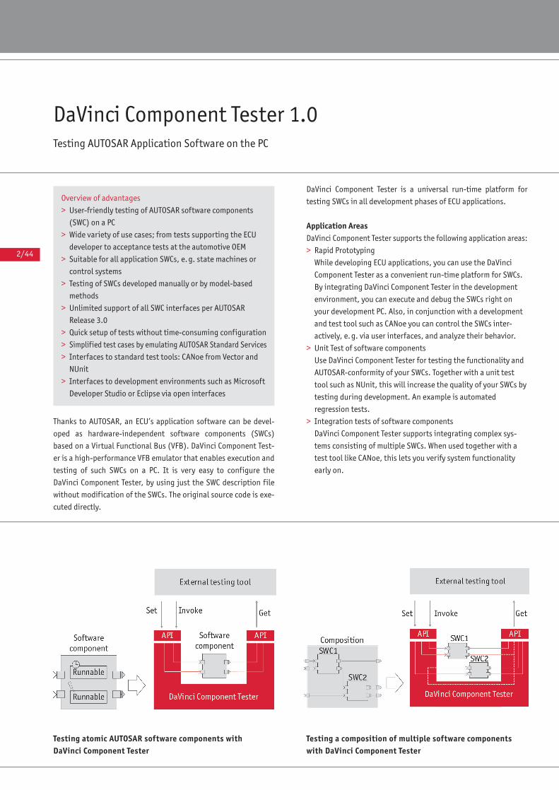
2/44
DaVinci Component Tester 1.0Testing AUTOSAR Application Software on the PC
Thanks to AUTOSAR, an ECU’s application software can be devel-
oped as hardware-independent software components (SWCs)
based on a Virtual Functional Bus (VFB). DaVinci Component Test-
er is a high-performance VFB emulator that enables execution and
testing of such SWCs on a PC. It is very easy to configure the
DaVinci Component Tester, by using just the SWC description file
without modification of the SWCs. The original source code is exe-
cuted directly.
DaVinci Component Tester is a universal run-time platform for
testing SWCs in all development phases of ECU applications.
Application AreasDaVinci Component Tester supports the following application areas:
> Rapid Prototyping
While developing ECU applications, you can use the DaVinci
Component Tester as a convenient run-time platform for SWCs.
By integrating DaVinci Component Tester in the development
environment, you can execute and debug the SWCs right on
your development PC. Also, in conjunction with a development
and test tool such as CANoe you can control the SWCs inter-
actively, e.g. via user interfaces, and analyze their behavior.
> Unit Test of software components
Use DaVinci Component Tester for testing the functionality and
AUTOSAR-conformity of your SWCs. Together with a unit test
tool such as NUnit, this will increase the quality of your SWCs by
testing during development. An example is automated
regression tests.
> Integration tests of software components
DaVinci Component Tester supports integrating complex sys-
tems consisting of multiple SWCs. When used together with a
test tool like CANoe, this lets you verify system functionality
early on.
Overview of advantages
> User-friendly testing of AUTOSAR software components
(SWC) on a PC
> Wide variety of use cases; from tests supporting the ECU
developer to acceptance tests at the automotive OEM
> Suitable for all application SWCs, e.g. state machines or
control systems
> Testing of SWCs developed manually or by model-based
methods
> Unlimited support of all SWC interfaces per AUTOSAR
Release 3.0
> Quick setup of tests without time-consuming configuration
> Simplified test cases by emulating AUTOSAR Standard Services
> Interfaces to standard test tools: CANoe from Vector and
NUnit
> Interfaces to development environments such as Microsoft
Developer Studio or Eclipse via open interfaces
Testing atomic AUTOSAR software components withDaVinci Component Tester
Testing a composition of multiple software componentswith DaVinci Component Tester
2/45
AUTOSAR
FunctionsThe core of DaVinci Component Tester is an emulator that executes
the SWCs on a PC. This does not require an AUTOSAR RTE (Runtime
Environment) or basic software. The finely tuned emulator simu-
lates the AUTOSAR-ECU environment for the SWC under test with
realistic behavior. The emulation covers full RTE functionality and
lets you test any AUTOSAR Release 3.0 SWCs using functions such
as:
> Setting data elements of receiver ports
> Reading data elements from sender ports
> Calling up server ports
> Controlling mode ports
> Setting calibration data
> Executing runnables with non-blocking API calls (Category I)
> Executing runnables with blocking API accesses (Category II)
> Handling internal communication between multiple SWCs
> Simulating errors such as timeout or empty queue
All you need to configure the test setup or experiments is the SWC
description (AUTOSAR XML file). Based on the SWC Description,
DaVinci Component Tester provides a structured API that can be
used by an external tool to access the SWC. The external test tool
handles control of the test, e.g. by programming test cases, and
evaluation of the test.
Operating ModesDaVinci Component Tester offers two operating modes, which
depend on its intended use. They affect execution of the SWC’s
runnable entities:
> Programmed execution mode
You can implement execution of the runnable entities in an
explicit test case. This execution mode is used in unit tests with
focus on detailed inspection of the implementation.
> Automatic execution mode
DaVinci Component Tester executes the runnable entities
independently according to the trigger specification, e.g.
periodically every 10 ms. Therefore DaVinci Component Tester
synchronizes itself to the time base of your test tool. This
execution mode is used for integration testing of complex SWCs
or in experimental startup of a SWC during development
(Rapid Prototyping).

Service EmulatorDaVinci Component Tester contains an emulator for the standard
services of an AUTOSAR ECU. This emulator simulates the behavior
of the services in an abstracted form.
When a test or experiment is set up, the SWC’s service ports are
automatically connected to the service emulator. There is no need
to explicitly consider the service ports in the test environment,
allowing you to focus entirely on the SWC’s application ports. This
reduces the complexity of the test environments considerably.
The service emulator may be accessed at any time. For example,
you can preset a block with a certain value that is read out by the
SWC from nonvolatile memory, or you can check the value chan-
ged by the SWC. Similarly, users can control or monitor the cur-
rent state of the ECU Manager from a test case.
The service emulator supports AUTOSAR standard services of the
following basic software modules:
> EcuM (ECU Manager)
> DEM (Diagnostic Event Manager)
> FiM (Function Inhibition Manager)
> NvM (Non-Volatile Memory Manager)
> ComM (Communication Manager)
> WdgM (Watchdog Manager)
Interface to CANoeYou can use DaVinci Component Tester in combination with CANoe
to execute integration tests of SWCs. While CANoe controls the
test flow, DaVinci Component Tester automatically handles execu-
tion of the runnable entities. Therefore DaVinci Component Tester
synchronizes itself to the simulation time of CANoe.
You describe the test environment in CANoe, e.g. with the help of
the Test Feature Set. All other CANoe functions are available as
well; such as panels, analysis windows and integration of MATLAB
models for an environment simulation.
2/46
Functional principle: Interfacing DaVinci Component Tester to CANoe
Special functions
> Instruction line support for automated tests
> Checking API consistency of the SWC Description and SWC
implementation file
> Programming callbacks in the test environment for specific
reaction to an API call of the SWC under test
> Generating the header file of SWCs (Contract Phase Gener-
ator) for compiling the SWC implementation with the
Microsoft Compiler
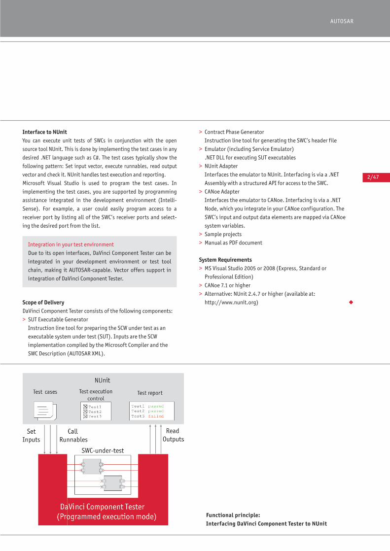
Interface to NUnitYou can execute unit tests of SWCs in conjunction with the open
source tool NUnit. This is done by implementing the test cases in any
desired .NET language such as C#. The test cases typically show the
following pattern: Set input vector, execute runnables, read output
vector and check it. NUnit handles test execution and reporting.
Microsoft Visual Studio is used to program the test cases. In
implementing the test cases, you are supported by programming
assistance integrated in the development environment (Intelli-
Sense). For example, a user could easily program access to a
receiver port by listing all of the SWC’s receiver ports and select-
ing the desired port from the list.
Scope of DeliveryDaVinci Component Tester consists of the following components:
> SUT Executable Generator
Instruction line tool for preparing the SCW under test as an
executable system under test (SUT). Inputs are the SCW
implementation compiled by the Microsoft Compiler and the
SWC Description (AUTOSAR XML).
> Contract Phase Generator
Instruction line tool for generating the SWC’s header file
> Emulator (including Service Emulator)
.NET DLL for executing SUT executables
> NUnit Adapter
Interfaces the emulator to NUnit. Interfacing is via a .NET
Assembly with a structured API for access to the SWC.
> CANoe Adapter
Interfaces the emulator to CANoe. Interfacing is via a .NET
Node, which you integrate in your CANoe configuration. The
SWC’s input and output data elements are mapped via CANoe
system variables.
> Sample projects
> Manual as PDF document
System Requirements> MS Visual Studio 2005 or 2008 (Express, Standard or
Professional Edition)
> CANoe 7.1 or higher
> Alternative: NUnit 2.4.7 or higher (available at:
http://www.nunit.org) ◆
2/47
AUTOSAR
Functional principle: Interfacing DaVinci Component Tester to NUnit
Integration in your test environment
Due to its open interfaces, DaVinci Component Tester can be
integrated in your development environment or test tool
chain, making it AUTOSAR-capable. Vector offers support in
integration of DaVinci Component Tester.
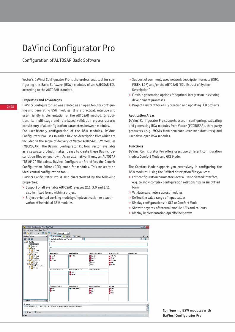
2/48
DaVinci Configurator ProConfiguration of AUTOSAR Basic Software
Vector’s DaVinci Configurator Pro is the professional tool for con-
figuring the Basic Software (BSW) modules of an AUTOSAR ECU
according to the AUTOSAR standard.
Properties and AdvantagesDaVinci Configurator Pro was created as an open tool for configur-
ing and generating BSW modules. It is a practical, intuitive and
user-friendly implementation of the AUTOSAR method. In addi-
tion, its multi-stage and rule-based validation process assures
consistency of all configuration parameters between modules.
For user-friendly configuration of the BSW modules, DaVinci
Configurator Pro uses so-called DaVinci description files which are
included in the scope of delivery of Vector AUTOSAR BSW modules
(MICROSAR). The DaVinci Configurator Kit from Vector, available
as a separate product, makes it easy to create these DaVinci de-
scription files on your own. As an alternative, if only an AUTOSAR
“BSWMD” file exists, DaVinci Configurator Pro offers the Generic
Configuration Editor (GCE) mode for modules. This makes it an
ideal central configuration tool.
DaVinci Configurator Pro is also characterized by the following
properties:
> Support of all available AUTOSAR releases (2.1, 3.0 and 3.1),
also in mixed forms within a project
> Project-oriented working mode by simple activation or deacti-
vation of individual BSW modules
> Support of commonly used network description formats (DBC,
FIBEX, LDF) and/or the AUTOSAR “ECU Extract of System
Description”
> Flexible generation options for optimal integration in existing
development processes
> Project assistant for easily creating and updating ECU projects
Application AreasDaVinci Configurator Pro supports users in configuring, validating
and generating BSW modules from Vector (MICROSAR), third party
producers (e.g. MCALs from semiconductor manufacturers) and
user-developed BSW modules.
FunctionsDaVinci Configurator Pro offers users two different configuration
modes: Comfort Mode and GCE Mode.
The Comfort Mode supports you extensively in configuring the
BSW modules. Using the DaVinci description files you can:
> Edit configuration parameters over a user-oriented interface,
e.g. to show complex configuration relationships in simplified
form
> Validate parameters across modules
> Define the value range of input values
> Display configurations in GCE or Comfort Mode
> Show the syntax of internal module APIs and callouts
> Display implementation-specific help texts
Configuring BSW modules withDaVinci Configurator Pro
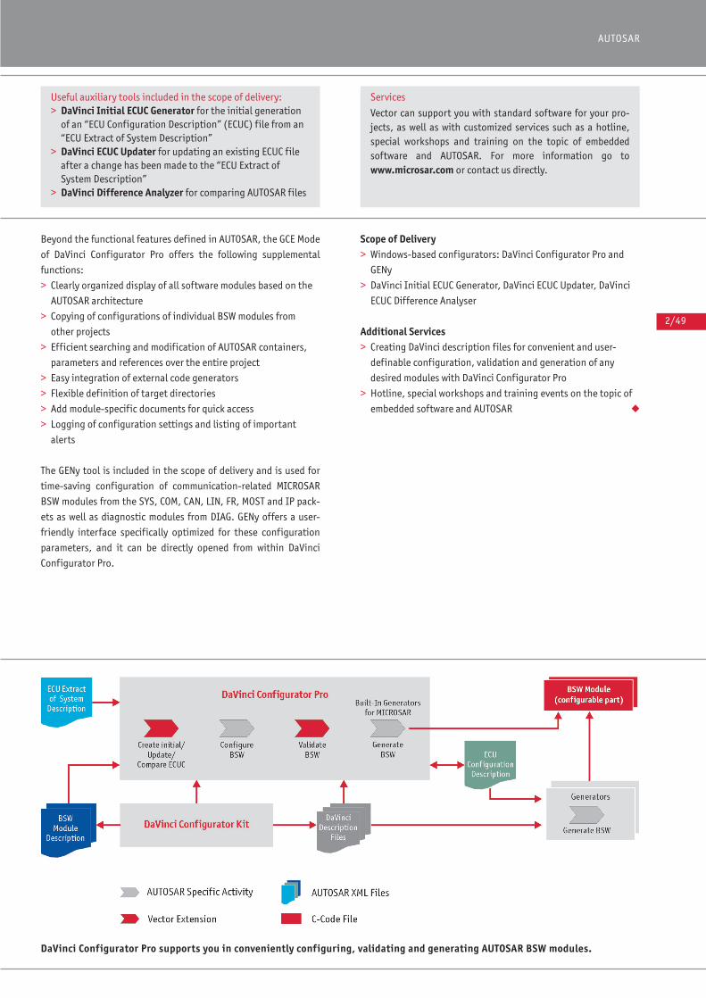
2/49
AUTOSAR
Beyond the functional features defined in AUTOSAR, the GCE Mode
of DaVinci Configurator Pro offers the following supplemental
functions:
> Clearly organized display of all software modules based on the
AUTOSAR architecture
> Copying of configurations of individual BSW modules from
other projects
> Efficient searching and modification of AUTOSAR containers,
parameters and references over the entire project
> Easy integration of external code generators
> Flexible definition of target directories
> Add module-specific documents for quick access
> Logging of configuration settings and listing of important
alerts
The GENy tool is included in the scope of delivery and is used for
time-saving configuration of communication-related MICROSAR
BSW modules from the SYS, COM, CAN, LIN, FR, MOST and IP pack-
ets as well as diagnostic modules from DIAG. GENy offers a user-
friendly interface specifically optimized for these configuration
parameters, and it can be directly opened from within DaVinci
Configurator Pro.
Scope of Delivery> Windows-based configurators: DaVinci Configurator Pro and
GENy
> DaVinci Initial ECUC Generator, DaVinci ECUC Updater, DaVinci
ECUC Difference Analyser
Additional Services> Creating DaVinci description files for convenient and user-
definable configuration, validation and generation of any
desired modules with DaVinci Configurator Pro
> Hotline, special workshops and training events on the topic of
embedded software and AUTOSAR ◆
DaVinci Configurator Pro supports you in conveniently configuring, validating and generating AUTOSAR BSW modules.
Useful auxiliary tools included in the scope of delivery:> DaVinci Initial ECUC Generator for the initial generation
of an “ECU Configuration Description” (ECUC) file from an“ECU Extract of System Description”
> DaVinci ECUC Updater for updating an existing ECUC fileafter a change has been made to the “ECU Extract of System Description”
> DaVinci Difference Analyzer for comparing AUTOSAR files
Services
Vector can support you with standard software for your pro-jects, as well as with customized services such as a hotline,special workshops and training on the topic of embeddedsoftware and AUTOSAR. For more information go towww.microsar.com or contact us directly.

2/50
DaVinci Configurator KitCreating configuration interfaces and generators for user-developed software modules
The AUTOSAR architecture currently defines approx. 50 configura-
ble standard Basic Software (BSW) modules. Each module is con-
figured to the needs of an individual ECU. DaVinci Configurator
Pro is the AUTOSAR configuration tool from Vector that is used to
configure all BSW modules.
You can extend DaVinci Configurator Pro (see separate datasheet)
with the DaVinci Configurator Kit, so that you can configure and
generate – in a time-saving and user friendly way – your own in-
house embedded software modules. This lets you concentrate ful-
ly on the development of your embedded software module, and
you will not need any additional configuration tool. You can also
use the DaVinci Configurator Kit to extend any desired software
module to prepare it for integration in an AUTOSAR ECU.
Conformance to the AUTOSAR standard is assured by Vector’s
many years of experience with AUTOSAR.
Properties and AdvantagesThe DaVinci Configurator Kit supports the embedded module
developer in designing individual configuration interfaces for
user-developed software modules and creating flexible code gen-
erators.
As a supplement to the AUTOSAR method, the DaVinci configura-
tion tools from Vector also offer a validation feature. Before code
generation it ensures that individually configured parameters as
well as complex parameter groups are consistent with one anoth-
er. For user-created software modules, you can also use the
DaVinci Configurator Kit to define the validation rules.
Application AreasThe DaVinci Configurator Kit supports developers of AUTOSAR
basic software modules, complex device drivers and user-devel-
oped software modules. Developers benefit from the simplified
process of creating configuration interfaces, validation rules and
generators without requiring knowledge of tool programming.
With just minimal effort it is possible to configure and integrate
complex device drivers in an existing AUTOSAR SW architecture.
Functions:The Vector DaVinci Configurator Kit lets you:
> Generate the AUTOSAR-conformant “BSW Module Description”
> Conveniently create configuration interfaces, validation rules
and generation processes for DaVinci Configurator Pro
> Define range and default values for configuration parameters
> Conveniently define your own configuration parameters
> Describe dependencies between different configuration
parameters – within a module or across modules
> Create your own code generators
> Easily define individual project reports that document the
parameter configuration in DaVinci Configurator Pro
> Extend the DaVinci Configurator Pro functionality by integrat-
ing your own C++ based DLLs
> Protect your own know-how by encrypting DaVinci description
files
DaVinci ConfiguratorKit supports you inintegrating your software module inDaVinci ConfiguratorPro

AUTOSAR
2/51
Scope of Delivery> DaVinci Configurator Pro (developer license)
> Tools for generating the DaVinci description files
> Extensive technical documentation of interfaces, as well as
numerous application examples
> Command line based code generator
> 3 days of training
> 20 hours of hotline support
Additional Services> Designing convenient configuration interfaces and supplemen-
tal validation rules for software modules of third party
producers, such as MCAL drivers or IO hardware abstraction
> Completely creating complex device drivers
> Extensions of AUTOSAR standard BSW modules
> Developing customer-specific AUTOSAR software components
(SWCs)
> Working out individual strategies for migration of your existing
systems to AUTOSAR
> Hotline, special workshops and training events on the topic of
embedded software and AUTOSAR ◆
ServicesVector can support you with standard software for your pro-jects, as well as with customized services such as a hotline,special workshops and training on the topic of embeddedsoftware and AUTOSAR. For more information go towww.microsar.com or contact us directly.
The following development tools are included with the DaVinci
Configurator Kit:
> Eparm to define and pre-configure individual parameters
for a module
> Clix to flexibly lay out user interfaces for displaying and
editing the module configuration in DaVinci Configurator
Pro
> Erule to create complex rules for data checking and file
generation
> Cryps to encrypt DaVinci description files created with
Eparm, Clix and Erule
> Elic to incorporate user-developed modules in existing
DaVinci Configurator Pro licenses
Defining a module’s configu-ration parameters with theEparm tool from the DaVinciConfigurator Kit.

2/52
AUTOSAR ServicesProficient support for your AUTOSAR projects
Our AUTOSAR Services support you in every phase of your ECU
development process. Based on your existing level of AUTOSAR
competence and your goals, we can work together with you to
plan and implement an individually tailored package. Advantages:
You improve the efficiency of your development activities and
build up AUTOSAR expertise within your organization by taking
advantage of our AUTOSAR experience.
AUTOSAR TrainingVector’s AUTOSAR training is the ideal entry for your ECU develop-
ment with AUTOSAR. Intensive training exercises guarantee its
practical value. For a list of Vector in-house training courses on
the Internet go to: www.vector.com/AUTOSAR-TrainingWe would be glad to conduct a workshop at your business site as
well. We can also adapt training contents to your individual
needs.
MICROSAR Startup WorkshopPerhaps you have already been working with AUTOSAR and would
now like to also use MICROSAR products on a specific project? In
our Startup Workshops, we can guide you through initial startup:
> Integrate MICROSAR components into your project structure
> Initialize the hardware, including CPU clock, PLL and Watchdog
> Configure the operating system
> Start up all CAN, LIN and FlexRay buses
> Start and stop communication as a function of the network state
> Provide the necessary I/O signal interfaces including signal
conditioning
> Integrate diagnostics, error memory and memory management
in the ECU software
> Link the applications to watchdog management
> Integrate the Vector Flash Bootloader including the OEM-
specific flash routine
MICROSAR Premium SupportAs a supplement to our Startup Workshop, or if you are already
quite familiar with our MICROSAR solution, we can offer you more
advanced support in the form of telephone or email support.
Upon request, we can also arrange to provide support right at
your business site.
Overview of advantages
> Efficient and effective way to build up an AUTOSAR
knowledge base
> Customized support
> Quick implementation of your application
2/53
AUTOSAR
MICROSAR CoachingOur MICROSAR Coaching is a combination of the Startup Workshop
and Premium Support. Our experts are available to you as primary
contacts for the duration of your project.
MICROSAR Solution WorkshopIn the framework of our solution workshops, our experts work
together with you to come up with solutions for your special pro-
ject requirements that help you:
> Optimally use the AUTOSAR tool chain
> Migrate your existing software to AUTOSAR architecture
> Use AUTOSAR OS
> Implement interfaces from I/O Hardware Abstraction to the RTE
> Add gateway functionality if necessary
> Structure MATLAB/Simulink models to link them to the RTE as
software components
> Link OEM or customer-specific software components to the RTE
> Optimally use NV Memory Management
> Implement ECU and Mode Management at start-up and
shut-down
> Come up with hardware-dependent Sleep and Wakeup concepts
that meet individual quiescent current requirements
> Optimize Watchdog Management
> Apply diagnostics based on OEM specifications
> Fulfill functional safety requirements (ISO DIS 26262)
AUTOSAR Project WorkAre you looking for a proficient software development partner for
your ECU project? Or perhaps you would like to focus more of your
time on application work or functional development? Vector can
handle your development packages for you:
> Create customized software components
> Configure and integrate all basic software including firmware,
I/O hardware abstraction, etc.
> Link your applications to the basic software
> Perform (model-based) development of all ECU software
Take advantage of our numerous years of experience and our
extensive expertise in developing software for the automotive
industry. ◆
For more information
On our “AUTOSAR Services” please contact us. Please find
your contact person at: www.vector.com/contact
Vector Katalog ECU Software EN 11.05.2010 11:33 Uhr Seite 2/53
3/0
Communication Software
The software implemented in automotive ECUs can be either infra-
structure software or application software. The latter implements
the desired functionality, while the infrastructure software in-
cludes the operating system, communication software and funda-
mental input and output services.
The use of uniform communication protocols is absolutely neces-
sary when setting up networks in a vehicle. The use of standard-
ized software components ensures easy portability and reliable
integration of ECUs in the vehicle’s network for the automotive
OEM and its suppliers. In addition, the software components lead
to a substantial reduction in development costs.
Software components in Conventional Systems without AUTOSAR Vector develops high-quality and innovative software components
for use in the automotive industry. One focus of the product line is
on ECU communication, an area in which Vector has well-founded
knowledge. The necessary hardware drivers are also important
here.
CANbedded products from Vector are available for systems without
AUTOSAR. You can obtain them for the CAN and LIN networks as
well as for the J1939 protocol. In addition, Vector can offer indi-
vidual solutions for further simplification of the application, e.g.
solutions for gateways or state management.
Communication Software for AUTOSAR SystemsVector also provides AUTOSAR-based communications software.
This software is available for the CAN, LIN, FlexRay, MOST and
Ethernet/IP bus systems. Further information and a description
of the available software modules can be found in the AUTOSAR
section beginning on page 2/0.
Your partner right from the startVector offers comprehensive support, from the start of a project
to its successful completion. Training sessions and courses pro-
vide basic information and in-depth knowledge on working with
the software – conducted in Vector’s classrooms or right at your
company. Vector can assist you through the ECU development
process with on-site startups, code reviews, project-specific serv-
ices and other development-supporting software tools.
CANopenFor CANopen communication, Vector offers source code for master
and slave ECUs. The source code contains all functions and serv-
ices required for the CANopen protocol, which are standardized by
CiA. Detailed information on this can be found beginning on page
3/22.
Uniform solutionNetwork communication is described in a database. It is used to
configure the software components and serves as a foundation
for Vector development and test tools. This gives software devel-
opers a universal and uniform solution, from simulation and
design to testing and validation.
Further information on tools for development and testing of auto-
motive networks can be found in the combined product catalog
“Development of distributed systems” and “ECU testing”.
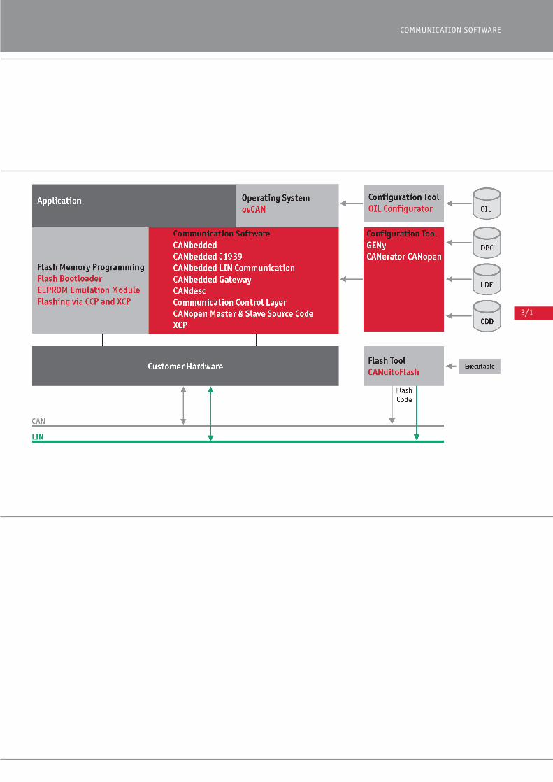
3/1
COMMUNICATION SOFTWARE

3/2
CANbeddedEmbedded Software for the Controller Area Network (CAN)
Overview on theCANbedded softwarecomponents
The Vector CANbedded environment consists of a number of con-
figurable source code components that provide functions which
cover the basic communication requirements in automotive appli-
cations. These functions – based on the CAN protocol – make it
possible to exchange information with other ECUs.
Features and AdvantagesThe Vector embedded software components provide a wide range
of features that are indispensable for ECUs in automotive applica-
tions. The software components integrate Vector’s experience in
the areas of embedded software and CAN communication:
> Standard components based on generic code that are scalable
for application-specific requirements
> Low ROM and RAM resource requirements
> Efficient run time
> Automatic generation of parameter settings and configuration
information
> Simple integration in application software
> Compatibility with Vector’s analysis, simulation and calibration
tools
> Compatibility with the requirements of automobile
manufacturers
You can use the PC-based configuration tool GENy to configure
the CANbedded software components for each target node.
For distributed applications in automotive networks, it is benefi-
cial if all ECUs contain an identical protocol stack. This will guar-
antee CAN bus compatibility.
> Reduced development costs for implementation and testing
> Highly optimized software algorithms make it possible to use
inexpensive hardware
> Careful development and wide usage in various ECUs makes
CANbedded very reliable.
FunctionsThe basic concept of CANbedded is to provide an interface that is
simple to use and can be used in all applications. The standard-
ized interface includes:
> Basic initialization of the hardware and software
> Cyclical call of the corresponding state machine (if timing
aspects are necessary)
> Functions needed to change the internal state of the CANbedded
software components.
Asynchronous events resulting from CAN bus activities such as
receiving messages, wake-up functions or different error states
are forwarded to the application via callback functions.
Some applications must run multiple CAN buses. For such applica-
tions, the CAN Driver – and often the higher CANbedded software
components as well – must provide a multi-channel interface;
therefore, all Vector software components are available in a multi-
channel version.
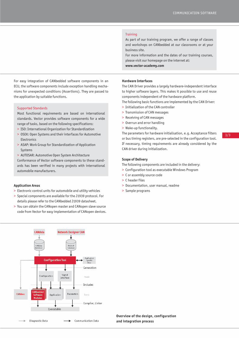
3/3
COMMUNICATION SOFTWARE
For easy integration of CANbedded software components in an
ECU, the software components include exception handling mecha-
nisms for unexpected conditions (Assertions). They are passed to
the application by suitable functions.
Application Areas> Electronic control units for automobile and utility vehicles
> Special components are available for the J1939 protocol. For
details please refer to the CANbedded J1939 datasheet.
> You can obtain the CANopen master and CANopen slave source
code from Vector for easy implementation of CANopen devices.
Hardware InterfacesThe CAN Driver provides a largely hardware-independent interface
to higher software layers. This makes it possible to use and reuse
components independent of the hardware platform.
The following basic functions are implemented by the CAN Driver:
> Initialization of the CAN controller
> Transmission of CAN messages
> Receiving of CAN messages
> Overrun and error handling
> Wake-up functionality.
The parameters for hardware initialisation, e.g. Acceptance filters
or bus timing registers, are pre-selected in the configuration tool.
If necessary, timing requirements are already considered by the
CAN driver during initialization.
Scope of DeliveryThe following components are included in the delivery:
> Configuration tool as executable Windows Program
> C or assembly source code
> C header files
> Documentation, user manual, readme
> Sample programs
Training
As part of our training program, we offer a range of classes
and workshops on CANbedded at our classrooms or at your
business site.
For more information and the dates of our training courses,
please visit our homepage on the internet at:
www.vector-academy.com
Supported Standards
Most functional requirements are based on international
standards. Vector provides software components for a wide
range of tasks, based on the following specifications:
> ISO: International Organization for Standardization
> OSEK: Open Systems and their interfaces for Automotive
Electronics
> ASAP: Work Group for Standardization of Application
Systems
> AUTOSAR: Automotive Open System Architecture
Conformance of Vector software components to these stand-
ards has been verified in many projects with international
automobile manufacturers.
Overview of the design, configurationand integration process
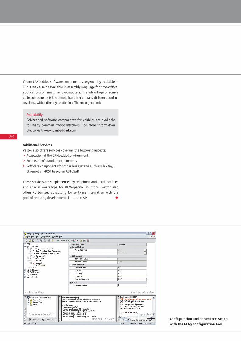
3/4
Vector CANbedded software components are generally available in
C, but may also be available in assembly language for time-critical
applications on small micro-computers. The advantage of source
code components is the simple handling of many different config-
urations, which directly results in efficient object code.
Additional ServicesVector also offers services covering the following aspects:
> Adaptation of the CANbedded environment
> Expansion of standard components
> Software components for other bus systems such as FlexRay,
Ethernet or MOST based on AUTOSAR
These services are supplemented by telephone and email hotlines
and special workshops for OEM-specific solutions. Vector also
offers customized consulting for software integration with the
goal of reducing development time and costs. ◆
Configuration and parameterizationwith the GENy configuration tool
Availability
CANbedded software components for vehicles are available
for many common microcontrollers. For more information
please visit: www.canbedded.com

3/5
COMMUNICATION SOFTWARE
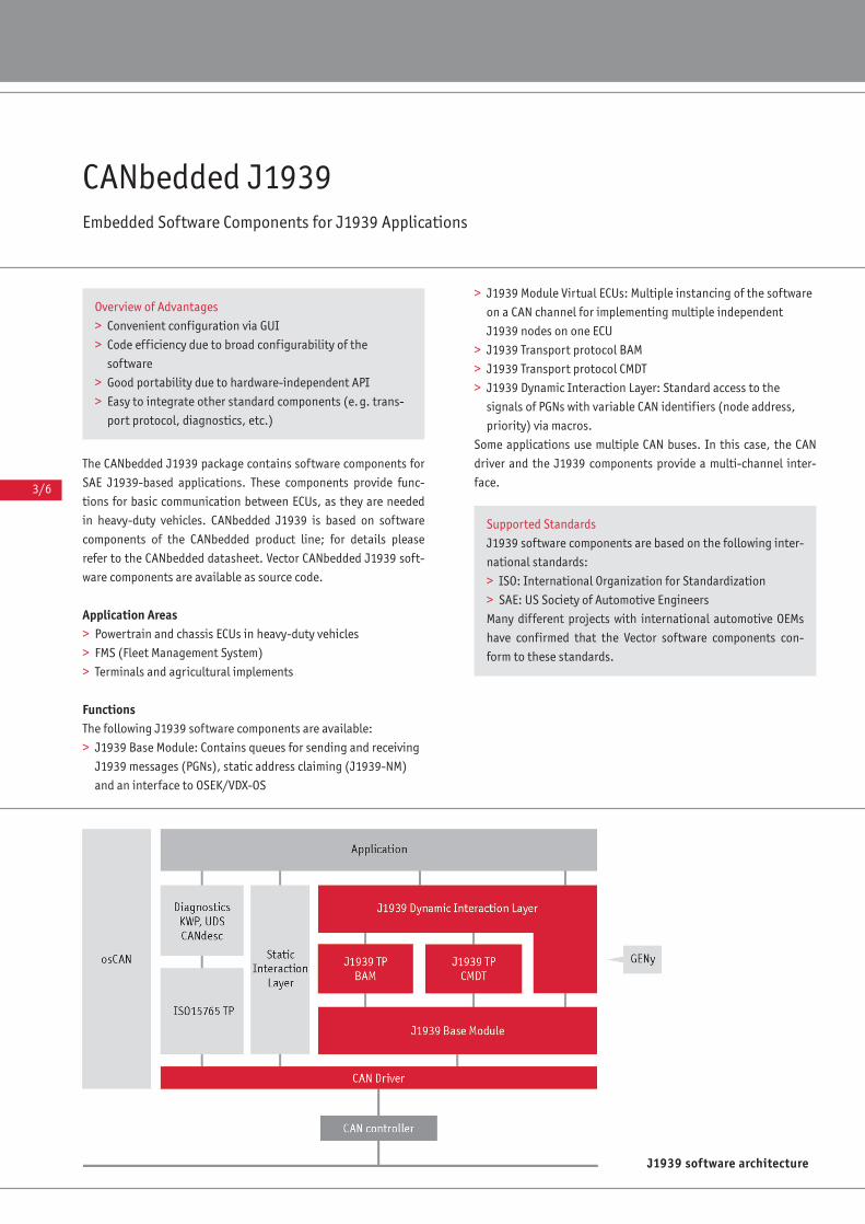
3/6
CANbedded J1939Embedded Software Components for J1939 Applications
The CANbedded J1939 package contains software components for
SAE J1939-based applications. These components provide func-
tions for basic communication between ECUs, as they are needed
in heavy-duty vehicles. CANbedded J1939 is based on software
components of the CANbedded product line; for details please
refer to the CANbedded datasheet. Vector CANbedded J1939 soft-
ware components are available as source code.
Application Areas> Powertrain and chassis ECUs in heavy-duty vehicles
> FMS (Fleet Management System)
> Terminals and agricultural implements
FunctionsThe following J1939 software components are available:
> J1939 Base Module: Contains queues for sending and receiving
J1939 messages (PGNs), static address claiming (J1939-NM)
and an interface to OSEK/VDX-OS
> J1939 Module Virtual ECUs: Multiple instancing of the software
on a CAN channel for implementing multiple independent
J1939 nodes on one ECU
> J1939 Transport protocol BAM
> J1939 Transport protocol CMDT
> J1939 Dynamic Interaction Layer: Standard access to the
signals of PGNs with variable CAN identifiers (node address,
priority) via macros.
Some applications use multiple CAN buses. In this case, the CAN
driver and the J1939 components provide a multi-channel inter-
face.
J1939 software architecture
Overview of Advantages
> Convenient configuration via GUI
> Code efficiency due to broad configurability of the
software
> Good portability due to hardware-independent API
> Easy to integrate other standard components (e.g. trans-
port protocol, diagnostics, etc.)
Supported Standards
J1939 software components are based on the following inter-
national standards:
> ISO: International Organization for Standardization
> SAE: US Society of Automotive Engineers
Many different projects with international automotive OEMs
have confirmed that the Vector software components con-
form to these standards.
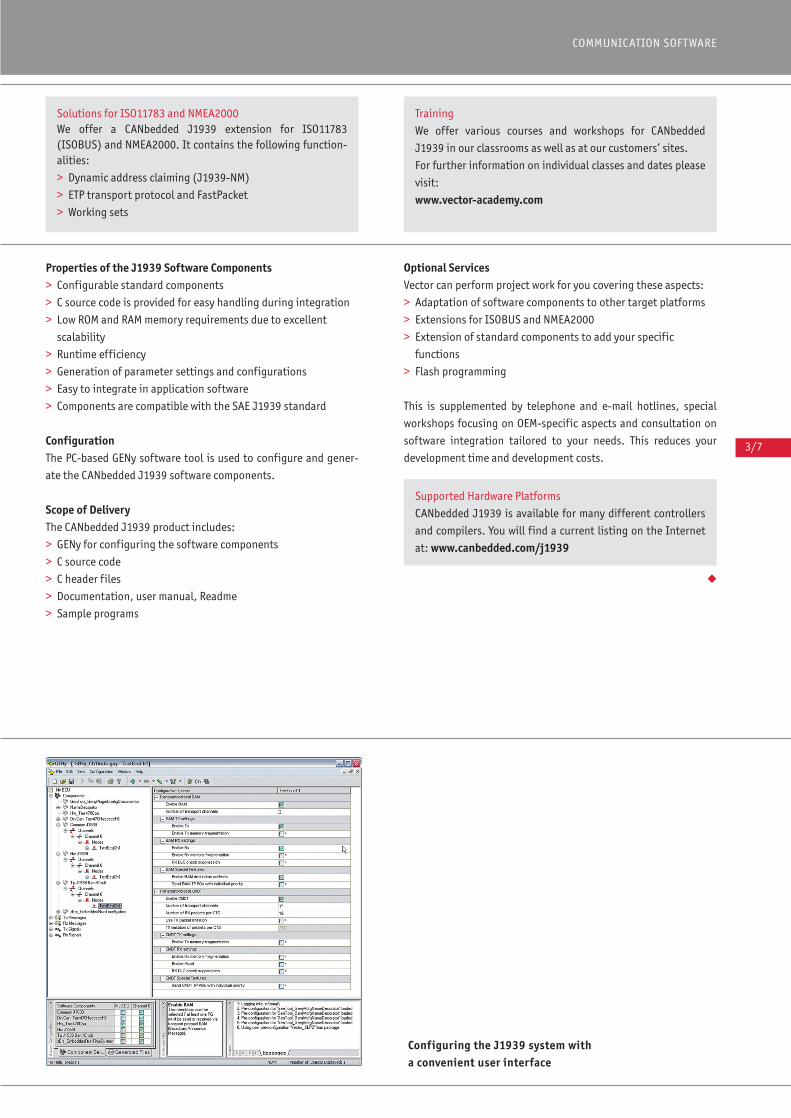
3/7
COMMUNICATION SOFTWARE
Properties of the J1939 Software Components> Configurable standard components
> C source code is provided for easy handling during integration
> Low ROM and RAM memory requirements due to excellent
scalability
> Runtime efficiency
> Generation of parameter settings and configurations
> Easy to integrate in application software
> Components are compatible with the SAE J1939 standard
ConfigurationThe PC-based GENy software tool is used to configure and gener-
ate the CANbedded J1939 software components.
Scope of DeliveryThe CANbedded J1939 product includes:
> GENy for configuring the software components
> C source code
> C header files
> Documentation, user manual, Readme
> Sample programs
Optional ServicesVector can perform project work for you covering these aspects:
> Adaptation of software components to other target platforms
> Extensions for ISOBUS and NMEA2000
> Extension of standard components to add your specific
functions
> Flash programming
This is supplemented by telephone and e-mail hotlines, special
workshops focusing on OEM-specific aspects and consultation on
software integration tailored to your needs. This reduces your
development time and development costs.
◆
Configuring the J1939 system witha convenient user interface
Solutions for ISO11783 and NMEA2000We offer a CANbedded J1939 extension for ISO11783 (ISOBUS) and NMEA2000. It contains the following function-alities:
> Dynamic address claiming (J1939-NM)
> ETP transport protocol and FastPacket
> Working sets
Training
We offer various courses and workshops for CANbedded
J1939 in our classrooms as well as at our customers’ sites.
For further information on individual classes and dates please
visit:
www.vector-academy.com
Supported Hardware Platforms
CANbedded J1939 is available for many different controllers
and compilers. You will find a current listing on the Internet
at: www.canbedded.com/j1939

3/8
LIN (Local Interconnect Network) is a cost-effective, serial com-
munication system for distributed electronic control units in the
motor vehicle. The LIN protocol is specified by the LIN Consor-
tium, of which Vector is an Associate Member.
Features and AdvantagesIncreasing software complexity makes it advantageous to imple-
ment standardized software components. Vector’s expertise ac-
quired in developing and working with other protocols has been
utilized throughout the development of LIN software components:
> Standard software components based on a portion of the gen-
erated code are scalable for application-specific requirements
> Automatic generation of parameter settings and configurations
> Runtime efficiency
> Low demand for ROM and RAM memory
> Simple interfacing to the application software
> Compatibility with other Vector products including analysis,
simulation, and calibration tools
> Support of LIN 1.2/1.3/2.0 and LIN 2.1
> Support of multi-channel LIN configurations
LIN networks are described in the LDF (LIN Description File) for-
mat according to the “LIN Configuration Language Specification”.
This includes all of the information needed to define signals, mes-
sages, baud rate and schedule tables. A configuration tool is used
to adapt all LIN software components to ECU-specific require-
ments. The tool imports either LDFs or NCF files (Node Capability
File) for parameterization.
Modifications and settings in detail:
> Adaptation of ECU-specific parameters to the network design
> Configuration of the LIN driver to the properties of the specific
ECU e.g. oscillator frequency, UART, etc.
> Configuration of diagnostic services for LIN Slave ECUs
> Definition of message and signal callbacks
The object codes of the LIN software components are compiled and
linked with the application. Vector’s LIN simulation and analysis
tools (e.g. CANoe.LIN and CANalyzer.LIN) are available for inte-
gration, analysis and for test purposes. For physical bus access one
of Vector’s XLI-Interface products can be purchased; these pro-
ducts serve as universal, serial bus interfaces for the LIN bus.
Timing control of the LIN software components is achieved by
having tasks called periodically by the application or an operating
system. Therefore the LIN driver does not require any auxiliary
timers.
FunctionsThe fundamental objective of the implementation is to provide an
interface that is easy to use and satisfies all applications. The
standardized interface offers these features:
> Initialization of the LIN hardware
> User-configurable baudrate (Recommended: 2400, 9600, and
19200 Baud)
> Sending of LIN messages (confirmation by flags and callback
functions)
CANbedded LIN CommunicationEmbedded Software Components for Local Interconnect Network
LIN and CAN Software Architecture
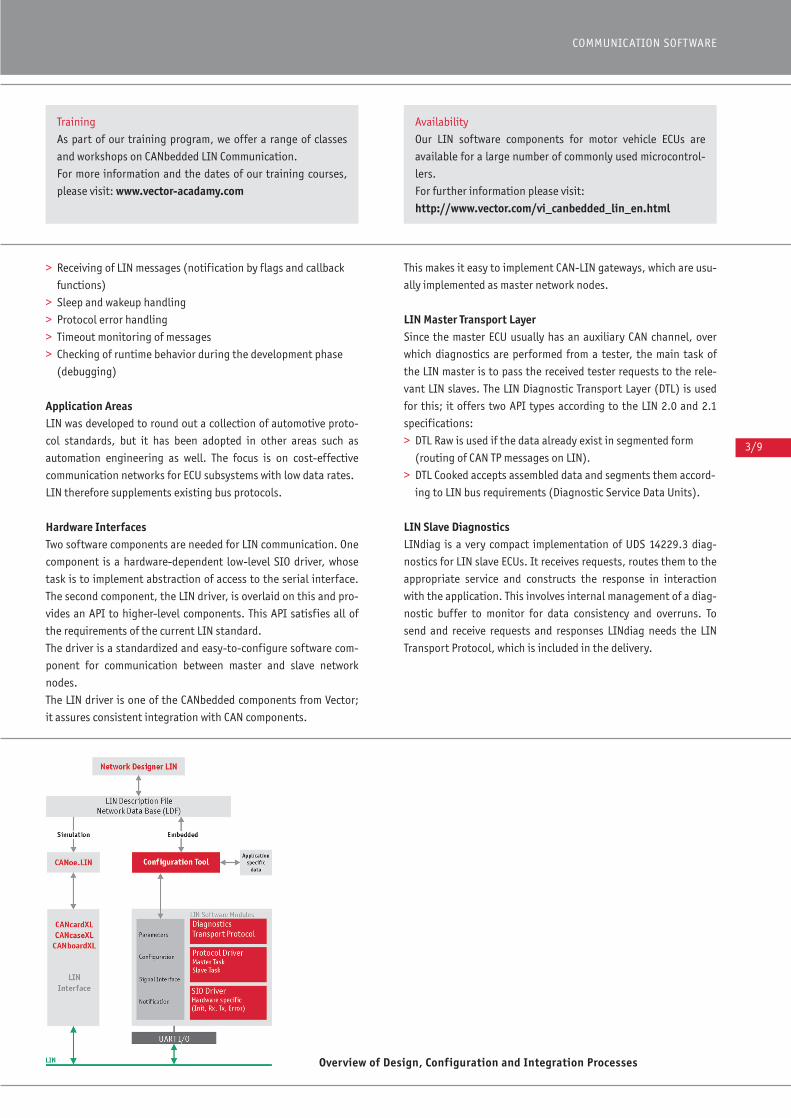
3/9
COMMUNICATION SOFTWARE
> Receiving of LIN messages (notification by flags and callback
functions)
> Sleep and wakeup handling
> Protocol error handling
> Timeout monitoring of messages
> Checking of runtime behavior during the development phase
(debugging)
Application AreasLIN was developed to round out a collection of automotive proto-
col standards, but it has been adopted in other areas such as
automation engineering as well. The focus is on cost-effective
communication networks for ECU subsystems with low data rates.
LIN therefore supplements existing bus protocols.
Hardware InterfacesTwo software components are needed for LIN communication. One
component is a hardware-dependent low-level SIO driver, whose
task is to implement abstraction of access to the serial interface.
The second component, the LIN driver, is overlaid on this and pro-
vides an API to higher-level components. This API satisfies all of
the requirements of the current LIN standard.
The driver is a standardized and easy-to-configure software com-
ponent for communication between master and slave network
nodes.
The LIN driver is one of the CANbedded components from Vector;
it assures consistent integration with CAN components.
This makes it easy to implement CAN-LIN gateways, which are usu-
ally implemented as master network nodes.
LIN Master Transport LayerSince the master ECU usually has an auxiliary CAN channel, over
which diagnostics are performed from a tester, the main task of
the LIN master is to pass the received tester requests to the rele-
vant LIN slaves. The LIN Diagnostic Transport Layer (DTL) is used
for this; it offers two API types according to the LIN 2.0 and 2.1
specifications:
> DTL Raw is used if the data already exist in segmented form
(routing of CAN TP messages on LIN).
> DTL Cooked accepts assembled data and segments them accord-
ing to LIN bus requirements (Diagnostic Service Data Units).
LIN Slave DiagnosticsLINdiag is a very compact implementation of UDS 14229.3 diag-
nostics for LIN slave ECUs. It receives requests, routes them to the
appropriate service and constructs the response in interaction
with the application. This involves internal management of a diag-
nostic buffer to monitor for data consistency and overruns. To
send and receive requests and responses LINdiag needs the LIN
Transport Protocol, which is included in the delivery.
Overview of Design, Configuration and Integration Processes
Training
As part of our training program, we offer a range of classes
and workshops on CANbedded LIN Communication.
For more information and the dates of our training courses,
please visit: www.vector-acadamy.com
Availability
Our LIN software components for motor vehicle ECUs are
available for a large number of commonly used microcontrol-
lers.
For further information please visit:
http://www.vector.com/vi_canbedded_lin_en.html
3/10
Further Options> Optional for slave ECUs: Diagnostic software components with
associated transport protocol
> Optional for master ECUs: Transport protocol with raw or
cooked API
> Gateway: CAN-LIN and LIN-LIN routing for master ECUs
> SAE J2602: As a supplemental option, support of the SAE J2602
“Recommended Practice” specification is available for LIN
drivers.
> Flashing of LIN slaves
Product ComponentsThe following items are supplied with the product:
> Configuration tool (executable Windows program)
> C sources for LIN driver and optional software components
> Sample programs
> Documentation and operating instructions
LicensesWhen the same hardware interface and same compiler are used
the acquired licenses can be used for all devices of a processor
type and any desired projects.
Supplemental ServicesVector also offers related project services such as:
> LIN driver expansions
> Support of other target hardware
> Development of higher OEM-specific protocol layers, e.g.
diagnostic protocol
Services also include telephone and e-mail hotlines, special work-
shops with OEM-specific focus and individualized consultation on
software integration with the goal of reducing development time
and costs. ◆

3/11
COMMUNICATION SOFTWARE
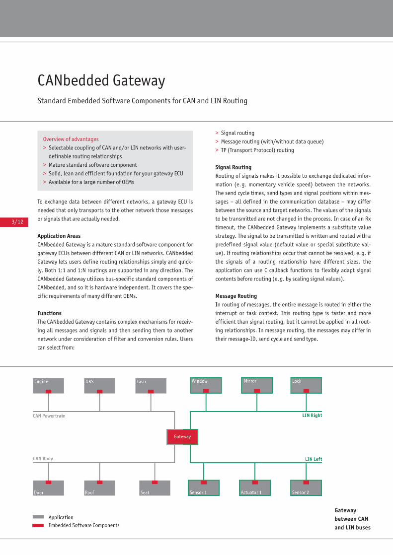
3/12
CANbedded GatewayStandard Embedded Software Components for CAN and LIN Routing
To exchange data between different networks, a gateway ECU is
needed that only transports to the other network those messages
or signals that are actually needed.
Application AreasCANbedded Gateway is a mature standard software component for
gateway ECUs between different CAN or LIN networks. CANbedded
Gateway lets users define routing relationships simply and quick-
ly. Both 1:1 and 1:N routings are supported in any direction. The
CANbedded Gateway utilizes bus-specific standard components of
CANbedded, and so it is hardware independent. It covers the spe-
cific requirements of many different OEMs.
Functions The CANbedded Gateway contains complex mechanisms for receiv-
ing all messages and signals and then sending them to another
network under consideration of filter and conversion rules. Users
can select from:
> Signal routing
> Message routing (with/without data queue)
> TP (Transport Protocol) routing
Signal RoutingRouting of signals makes it possible to exchange dedicated infor-
mation (e.g. momentary vehicle speed) between the networks.
The send cycle times, send types and signal positions within mes-
sages – all defined in the communication database – may differ
between the source and target networks. The values of the signals
to be transmitted are not changed in the process. In case of an Rx
timeout, the CANbedded Gateway implements a substitute value
strategy. The signal to be transmitted is written and routed with a
predefined signal value (default value or special substitute val-
ue). If routing relationships occur that cannot be resolved, e.g. if
the signals of a routing relationship have different sizes, the
application can use C callback functions to flexibly adapt signal
contents before routing (e.g. by scaling signal values).
Message RoutingIn routing of messages, the entire message is routed in either the
interrupt or task context. This routing type is faster and more
efficient than signal routing, but it cannot be applied in all rout-
ing relationships. In message routing, the messages may differ in
their message-ID, send cycle and send type.
Gateway between CANand LIN buses
Overview of advantages
> Selectable coupling of CAN and/or LIN networks with user-
definable routing relationships
> Mature standard software component
> Solid, lean and efficient foundation for your gateway ECU
> Available for a large number of OEMs
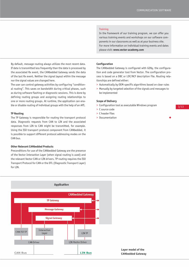
3/13
COMMUNICATION SOFTWARE
By default, message routing always utilizes the most recent data.
If data is transmitted less frequently than the data is processed by
the associated Rx event, the CANbedded Gateway sends the data
of the last Rx event. Neither the signal layout within the message
nor the signal values are changed here.
The user can control gateway activities by configuring “condition-
al routing”. This saves on bandwidth during critical phases, such
as during software flashing or diagnostic sessions. This is done by
defining routing groups and assigning routing relationships to
one or more routing groups. At runtime, the application can ena-
ble or disable routing of individual groups with the help of an API.
TP RoutingThe TP Gateway is responsible for routing the transport protocol
data. Diagnostic requests from CAN to LIN and the associated
responses from LIN to CAN might be transmitted, for example.
Using the ISO transport protocol component from CANbedded, it
is possible to support different protocol addressing modes on the
CAN bus.
Other Relevant CANbedded ProductsPreconditions for use of the CANbedded Gateway are the presence
of the Vector Interaction Layer (when signal routing is used) and
the relevant Vector CAN or LIN drivers. TP routing requires the ISO
Transport Protocol for CAN or the DTL (Diagnostic Transport Layer)
for LIN.
ConfigurationThe CANbedded Gateway is configured with GENy, the configura-
tion and code generator tool from Vector. The configuration pro-
cess is based on a DBC or LDF/NCF description file. Routing rela-
tionships are defined either:
> Automatically by OEM-specific algorithms based on clear rules
> Manually by targeted selection of the signals and messages to
be implemented
Scope of Delivery> Configuration tool as executable Windows program
> C source code
> C header files
> Documentation ◆
Training
In the framework of our training program, we can offer you
various training events and workshops on our software com-
ponents in our classrooms as well as at your business site.
For more information on individual training events and dates
please visit: www.vector-academy.com
Layer model of the CANbedded Gateway
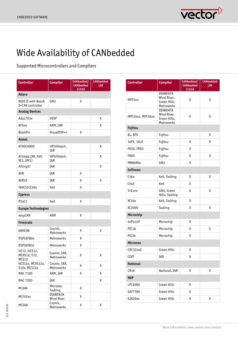
EMBEDDED SOFTWARE
More Information: www.vector.com/contact
V2.0
201
0-05
Controller Compiler CANbedded/ CANbedded
J1939
CANbedded LIN
Altera
NIOS II with Bosch D-CAN controller
GNU X
Analog Devices
Aduc703x VDSP X
BF5xx ARM, IAR X
Blackfin VisualDSP++ X
Atmel
AT90CANXX HPInfotech, IAR
X
ATmega (X8, X4P, XC1, XM1)
HPInfotech, IAR
X
ATtinyX7 IAR X
AVR IAR X
AVR32 IAR X X
T89C51CC00x Keil X
Cypress
PSoC3 Keil X
Europe Technologies
easyCAN ARM X
Freescale
68HC08 Cosmic, Metrowerks X X
DSP56F80x Metrowerks X
DSP56F83x Metrowerks X
HC12, HCS12, MC9S12, S12, MCS12
Cosmic, IAR, Metrowerks X X
HCS12x, MC9S12x, S12x, MCS12x
Cosmic, IAR, Metrowerks X X
MAC 7100 ARM, IAR X X
MAC 7200 IAR X
MC68k Microtec, Tasking X
MCF52xx DIABDATA Wind River X
MCS08 Cosmic, Metrowerks X X
Controller Compiler CANbedded/ CANbedded
J1939
CANbedded LIN
MPC5xx
DIABDATA Wind River, Green Hills, Metrowerks
X X
MPC55xx, MPC56xx
DIABDATA Wind River, Green Hills, Metrowerks
X X
Fujitsu
8L, 8FX Fujitsu X
16FX, 16LX Fujitsu X X
FR30, FR50 Fujitsu X
FR60 Fujitsu X X
MB86R0x GNU X
Infineon
C16x Keil, Tasking X X
C5x5 Keil X
TriCore GNU, Green Hills, Tasking
X X
XC16x Keil, Tasking X
XC2000 Tasking X X
Microchip
dsPic33F Microchip X
PIC18 Microchip X X
PIC24 Microchip X
Micronas
CDC32xxG Green Hills X
CEVF IAR X
National
CR16 National, IAR X X
NXP
LPC2000 Green Hills X
SAF7780 Green Hills X
SJA20xx Green Hills X X
Wide Availability of CANbedded Supported Microcontrollers and Compilers
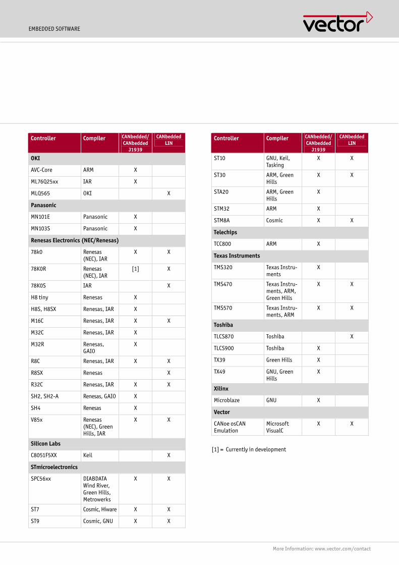
EMBEDDED SOFTWARE
More Information: www.vector.com/contact
Controller Compiler CANbedded/ CANbedded
J1939
CANbedded LIN
OKI
AVC-Core ARM X
ML76Q25xx IAR X
MLQ565 OKI X
Panasonic
MN101E Panasonic X
MN103S Panasonic X
Renesas Electronics (NEC/Renesas)
78k0 Renesas (NEC), IAR
X X
78K0R Renesas (NEC), IAR
[1] X
78K0S IAR X
H8 tiny Renesas X
H8S, H8SX Renesas, IAR X
M16C Renesas, IAR X X
M32C Renesas, IAR X
M32R Renesas, GAIO
X
R8C Renesas, IAR X X
R8SX Renesas X
R32C Renesas, IAR X X
SH2, SH2-A Renesas, GAIO X
SH4 Renesas X
V85x Renesas (NEC), Green Hills, IAR
X X
Silicon Labs
C8051F5XX Keil X
STmicroelectronics
SPC56xx DIABDATA Wind River, Green Hills, Metrowerks
X X
ST7 Cosmic, Hiware X X
ST9 Cosmic, GNU X X
Controller Compiler CANbedded/ CANbedded
J1939
CANbedded LIN
ST10 GNU, Keil, Tasking
X X
ST30 ARM, Green Hills
X X
STA20 ARM, Green Hills
X
STM32 ARM X
STM8A Cosmic X X
Telechips
TCC800 ARM X
Texas Instruments
TMS320 Texas Instru-ments
X
TMS470 Texas Instru-ments, ARM, Green Hills
X X
TMS570 Texas Instru-ments, ARM
X X
Toshiba
TLCS870 Toshiba X
TLCS900 Toshiba X
TX39 Green Hills X
TX49 GNU, Green Hills
X
Xilinx
Microblaze GNU X
Vector
CANoe osCAN Emulation
Microsoft VisualC
X X
[1] = Currently in development
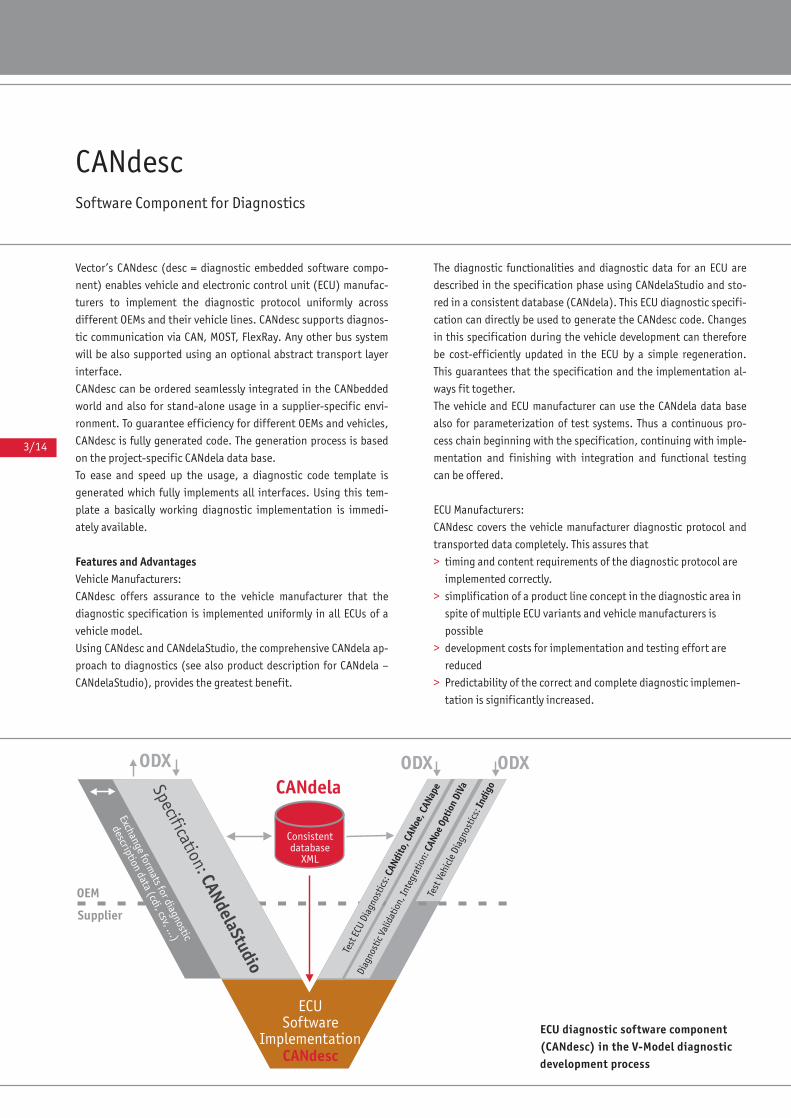
3/14
CANdescSoftware Component for Diagnostics
Vector’s CANdesc (desc = diagnostic embedded software compo-
nent) enables vehicle and electronic control unit (ECU) manufac-
turers to implement the diagnostic protocol uniformly across
different OEMs and their vehicle lines. CANdesc supports diagnos-
tic communication via CAN, MOST, FlexRay. Any other bus system
will be also supported using an optional abstract transport layer
interface.
CANdesc can be ordered seamlessly integrated in the CANbedded
world and also for stand-alone usage in a supplier-specific envi-
ronment. To guarantee efficiency for different OEMs and vehicles,
CANdesc is fully generated code. The generation process is based
on the project-specific CANdela data base.
To ease and speed up the usage, a diagnostic code template is
generated which fully implements all interfaces. Using this tem-
plate a basically working diagnostic implementation is immedi-
ately available.
Features and AdvantagesVehicle Manufacturers:
CANdesc offers assurance to the vehicle manufacturer that the
diagnostic specification is implemented uniformly in all ECUs of a
vehicle model.
Using CANdesc and CANdelaStudio, the comprehensive CANdela ap-
proach to diagnostics (see also product description for CANdela –
CANdelaStudio), provides the greatest benefit.
The diagnostic functionalities and diagnostic data for an ECU are
described in the specification phase using CANdelaStudio and sto-
red in a consistent database (CANdela). This ECU diagnostic specifi-
cation can directly be used to generate the CANdesc code. Changes
in this specification during the vehicle development can therefore
be cost-efficiently updated in the ECU by a simple regeneration.
This guarantees that the specification and the implementation al-
ways fit together.
The vehicle and ECU manufacturer can use the CANdela data base
also for parameterization of test systems. Thus a continuous pro-
cess chain beginning with the specification, continuing with imple-
mentation and finishing with integration and functional testing
can be offered.
ECU Manufacturers:
CANdesc covers the vehicle manufacturer diagnostic protocol and
transported data completely. This assures that
> timing and content requirements of the diagnostic protocol are
implemented correctly.
> simplification of a product line concept in the diagnostic area in
spite of multiple ECU variants and vehicle manufacturers is
possible
> development costs for implementation and testing effort are
reduced
> Predictability of the correct and complete diagnostic implemen-
tation is significantly increased.
ECU diagnostic software component(CANdesc) in the V-Model diagnosticdevelopment process

3/15
COMMUNICATION SOFTWARE
FunctionsAll vehicle manufacturer specific diagnostic features are imple-
mented and encapsulated in CANdesc. This gives the ECU applica-
tion a clear signal interface. Reutilization of the ECU application is
thereby supported.
CANdesc covers
> support of the total manufacturer-specific diagnostic protocol
with all functional and timing constraints
> full implementation of communication related diagnostic
services (e.g. $28 CommunicationControl)
> implementation of “data unit” handling ($2A, $2C) according to
the OEM specification
> filtering of diagnostic requests according to service, session,
service instance, format, session of service instance and security
> correct responses to diagnostic requests
> state management (depending on the CANdela database e.g.
session and security handling)
> generation of a diagnostic data buffer and preservation of data
consistency between application and diagnostic request
(functional, physical and multiple simultaneous)
Application Areas> ECUs for passenger cars and commercial vehicles
> CANdesc can be used on CAN, MOST, FlexRay and any other
communication system
> Seamlessly embedded in the CANbedded world but can also be
used as a stand-alone component.
Product Components> Executable Windows program (generation tool) with the
CANdesc Option
> Documentation/User Manual
Supplemental ServicesVector offers the following types of project services:
> Adaptation of the application to CANdesc
> Implementation of fault memory concepts
> Process consultation services in the diagnostic area
> Testing of ECU diagnostic implementation ◆
Example of Code Size
Microprocessor: Motorola HC12, MC9S12DP256; Cosmic-Compiler 4.5 with an implementation of 10 diagnostic services and 30 sub
functions with the data packets:
Code size: approx. 5.5 kB; tables and constants: approx. 700 bytes;
RAM: approx. 70 bytes plus bytes for the diagnostic buffer.
For average sized applications with approx. 120 sub functions the code size increases to approx. 9 kB.
Generation of ECU diagnostic softwarecomponent
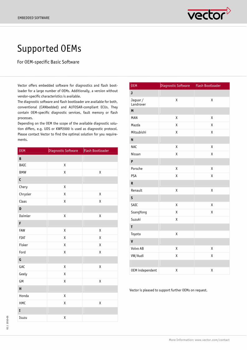
EMBEDDED SOFTWARE
More Information: www.vector.com/contact
V2.1
201
0-05
Vector offers embedded software for diagnostics and flash boot-
loader for a large number of OEMs. Additionally, a version without
vendor-specific characteristics is available.
The diagnostic software and flash bootloader are available for both,
conventional (CANbedded) and AUTOSAR-compliant ECUs. They
contain OEM-specific diagnostic services, fault memory or flash
processes.
Depending on the OEM the scope of the available diagnostic solu-
tion differs, e.g. UDS or KWP2000 is used as diagnostic protocol.
Please contact Vector to find the optimal solution for you require-
ments.
OEM Diagnostic Software Flash Bootloader
B
BAIC X
BMW X X
C
Chery X
Chrysler X X
Claas X X
D
Daimler X X
F
FAW X X
FIAT X X
Fisker X X
Ford X X
G
GAC X X
Geely X
GM X X
H
Honda X
HMC X X
I
Isuzu X
OEM Diagnostic Software Flash Bootloader
J
Jaguar / Landrover
X X
M
MAN X X
Mazda X X
Mitsubishi X X
N
NAC X X
Nissan X X
P
Porsche X X
PSA X X
R
Renault X X
S
SAIC X X
SsangYong X X
Suzuki X
T
Toyota X
V
Volvo AB X X
VW/Audi X X
OEM independent X X
Vector is pleased to support further OEMs on request.
Supported OEMs For OEM-specific Basic Software
EMBEDDED SOFTWARE
More Information: www.vector.com/contact
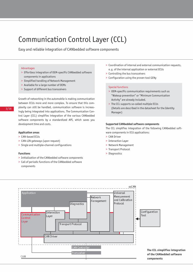
3/16
Communication Control Layer (CCL)Easy and reliable integration of CANbedded software components
Growth of networking in the automobile is making communication
between ECUs more and more complex. To ensure that this com-
plexity can still be handled, communication software is increas-
ingly being integrated into applications. The Communication Con-
trol Layer (CCL) simplifies integration of the various CANbedded
software components by a standardized API, which saves you
development time and costs.
Application areas> CAN-based ECUs
> CAN-LIN gateways (upon request)
> Single and multiple-channel configurations
Functions> Initialization of the CANbedded software components
> Call of periodic functions of the CANbedded software
components
> Coordination of internal and external communication requests,
e.g. of the internal application or external ECUs
> Controlling the bus transceivers
> Configuration using the proven tool GENy
Supported CANbedded software componentsThe CCL simplifies integration of the following CANbedded soft-
ware components in ECU applications:
> CAN Driver
> Interaction Layer
> Network Management
> Transport Protocol
> Diagnostics
Advantages
> Effortless integration of OEM-specific CANbedded software
components in applications
> Simplified handling of Network Management
> Available for a large number of OEMs
> Support of different bus transceiversSpecial functions
> OEM-specific communication requirements such as
“Wakeup prevention” or “Minimum Communication
Activity” are already included.
> The CCL supports so-called multiple ECUs
(Details are described in the datasheet for the Identity
Manager)
The CCL simplifies integrationof the CANbedded softwarecomponents
3/17
COMMUNICATION SOFTWARE
Periodic functionsThe CCL simplifies calling the periodic functions of the CANbedded
software components, e.g. timer tasks or state tasks. A scheduler
integrated in the CCL may be used to call them based on their cy-
cle times. However, separate operating system tasks may also be
used to call the periodic functions of the components. Besides
these two options, there are other configuration options as well.
To optimize ECU performance, select the optimal solution in your
configuration.
Start and stop of communicationThe CCL contains an interface for controlling communication. It
coordinates the various communication requests: internal re-
quests from the application and external requests from other
ECUs. The CCL either starts or stops the communication depend-
ing on these requests.
ConfigurationThe CCL can be configured with the configuration tool GENy. In
this process, GENy utilizes information from the communication
database (e.g. the DBC file from the OEM) as well as the user’s
manual settings.
GENy generates parameterization files based on the configura-
tion. They contain the parameters and function calls of the com-
ponents being used. For example, the recommended initialization
sequence of the components is taken into consideration.
AvailabilityTo ensure that user requirements are supported, the CCL is avail-
able for a large number of:
> OEMs and
> CAN transceivers
Hardware-independent programming supports a wide variety of
microcontrollers, compilers, linkers and CAN Controllers.
Please ask Vector to quote your required configuration:
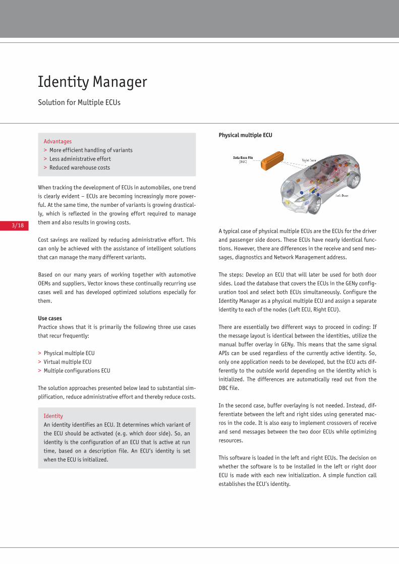
3/18
Identity ManagerSolution for Multiple ECUs
When tracking the development of ECUs in automobiles, one trend
is clearly evident – ECUs are becoming increasingly more power-
ful. At the same time, the number of variants is growing drastical-
ly, which is reflected in the growing effort required to manage
them and also results in growing costs.
Cost savings are realized by reducing administrative effort. This
can only be achieved with the assistance of intelligent solutions
that can manage the many different variants.
Based on our many years of working together with automotive
OEMs and suppliers, Vector knows these continually recurring use
cases well and has developed optimized solutions especially for
them.
Use casesPractice shows that it is primarily the following three use cases
that recur frequently:
> Physical multiple ECU
> Virtual multiple ECU
> Multiple configurations ECU
The solution approaches presented below lead to substantial sim-
plification, reduce administrative effort and thereby reduce costs.
Physical multiple ECU
A typical case of physical multiple ECUs are the ECUs for the driver
and passenger side doors. These ECUs have nearly identical func-
tions. However, there are differences in the receive and send mes-
sages, diagnostics and Network Management address.
The steps: Develop an ECU that will later be used for both door
sides. Load the database that covers the ECUs in the GENy config-
uration tool and select both ECUs simultaneously. Configure the
Identity Manager as a physical multiple ECU and assign a separate
identity to each of the nodes (Left ECU, Right ECU).
There are essentially two different ways to proceed in coding: If
the message layout is identical between the identities, utilize the
manual buffer overlay in GENy. This means that the same signal
APIs can be used regardless of the currently active identity. So,
only one application needs to be developed, but the ECU acts dif-
ferently to the outside world depending on the identity which is
initialized. The differences are automatically read out from the
DBC file.
In the second case, buffer overlaying is not needed. Instead, dif-
ferentiate between the left and right sides using generated mac-
ros in the code. It is also easy to implement crossovers of receive
and send messages between the two door ECUs while optimizing
resources.
This software is loaded in the left and right ECUs. The decision on
whether the software is to be installed in the left or right door
ECU is made with each new initialization. A simple function call
establishes the ECU’s identity.
Advantages
> More efficient handling of variants
> Less administrative effort
> Reduced warehouse costs
Identity
An identity identifies an ECU. It determines which variant of
the ECU should be activated (e.g. which door side). So, an
identity is the configuration of an ECU that is active at run
time, based on a description file. An ECU’s identity is set
when the ECU is initialized.
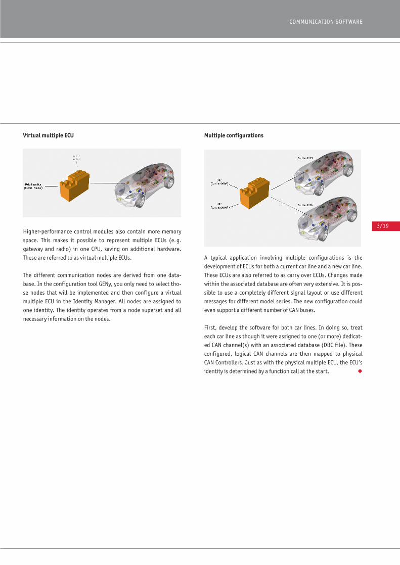
3/19
COMMUNICATION SOFTWARE
Virtual multiple ECU
Higher-performance control modules also contain more memory
space. This makes it possible to represent multiple ECUs (e.g.
gateway and radio) in one CPU, saving on additional hardware.
These are referred to as virtual multiple ECUs.
The different communication nodes are derived from one data-
base. In the configuration tool GENy, you only need to select tho-
se nodes that will be implemented and then configure a virtual
multiple ECU in the Identity Manager. All nodes are assigned to
one identity. The identity operates from a node superset and all
necessary information on the nodes.
Multiple configurations
A typical application involving multiple configurations is the
development of ECUs for both a current car line and a new car line.
These ECUs are also referred to as carry over ECUs. Changes made
within the associated database are often very extensive. It is pos-
sible to use a completely different signal layout or use different
messages for different model series. The new configuration could
even support a different number of CAN buses.
First, develop the software for both car lines. In doing so, treat
each car line as though it were assigned to one (or more) dedicat-
ed CAN channel(s) with an associated database (DBC file). These
configured, logical CAN channels are then mapped to physical
CAN Controllers. Just as with the physical multiple ECU, the ECU’s
identity is determined by a function call at the start. ◆
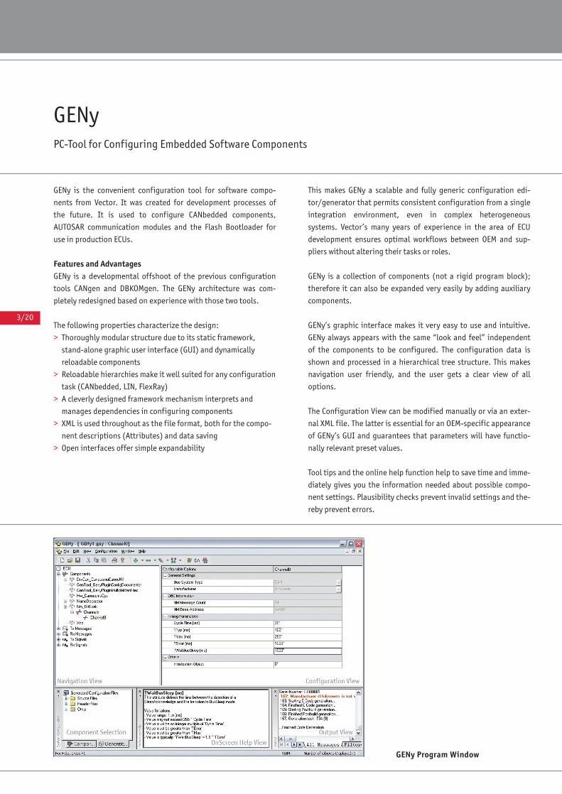
3/20
GENyPC-Tool for Configuring Embedded Software Components
GENy is the convenient configuration tool for software compo-
nents from Vector. It was created for development processes of
the future. It is used to configure CANbedded components,
AUTOSAR communication modules and the Flash Bootloader for
use in production ECUs.
Features and AdvantagesGENy is a developmental offshoot of the previous configuration
tools CANgen and DBKOMgen. The GENy architecture was com-
pletely redesigned based on experience with those two tools.
The following properties characterize the design:
> Thoroughly modular structure due to its static framework,
stand-alone graphic user interface (GUI) and dynamically
reloadable components
> Reloadable hierarchies make it well suited for any configuration
task (CANbedded, LIN, FlexRay)
> A cleverly designed framework mechanism interprets and
manages dependencies in configuring components
> XML is used throughout as the file format, both for the compo-
nent descriptions (Attributes) and data saving
> Open interfaces offer simple expandability
This makes GENy a scalable and fully generic configuration edi-
tor/generator that permits consistent configuration from a single
integration environment, even in complex heterogeneous
systems. Vector’s many years of experience in the area of ECU
development ensures optimal workflows between OEM and sup-
pliers without altering their tasks or roles.
GENy is a collection of components (not a rigid program block);
therefore it can also be expanded very easily by adding auxiliary
components.
GENy’s graphic interface makes it very easy to use and intuitive.
GENy always appears with the same “look and feel” independent
of the components to be configured. The configuration data is
shown and processed in a hierarchical tree structure. This makes
navigation user friendly, and the user gets a clear view of all
options.
The Configuration View can be modified manually or via an exter-
nal XML file. The latter is essential for an OEM-specific appearance
of GENy’s GUI and guarantees that parameters will have functio-
nally relevant preset values.
Tool tips and the online help function help to save time and imme-
diately gives you the information needed about possible compo-
nent settings. Plausibility checks prevent invalid settings and the-
reby prevent errors.
GENy Program Window
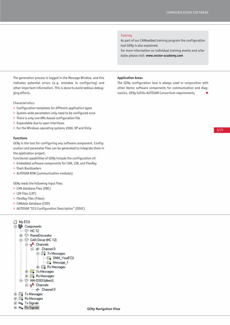
3/21
COMMUNICATION SOFTWARE
The generation process is logged in the Message Window, and this
indicates potential errors (e.g. mistakes in configuring) and
other important information. This is done to avoid tedious debug-
ging efforts.
Characteristics:
> Configuration templates for different application types
> System-wide parameters only need to be configured once
> There is only one XML-based configuration file
> Expandable due to open interfaces
> For the Windows operating systems 2000, XP and Vista
FunctionsGENy is the tool for configuring any software component. Config-
uration and parameter files can be generated to integrate them in
the application project.
Functional capabilities of GENy include the configuration of:
> Embedded software components for CAN, LIN, and FlexRay
> Flash Bootloaders
> AUTOSAR BSW (communication modules)
GENy reads the following input files:
> CAN database files (DBC)
> LIN files (LDF)
> FlexRay files (Fibex)
> CANdela database (CDD)
> AUTOSAR “ECU Configuration Description” (EDUC)
Application AreasThe GENy configuration tool is always used in conjunction with
other Vector software components for communication and diag-
nostics. GENy fulfills AUTOSAR Consortium requirements. ◆
GENy Navigation View
Training
As part of our CANbedded training program the configuration
tool GENy is also explained.
For more information on individual training events and sche-
dules please visit: www.vector-academy.com
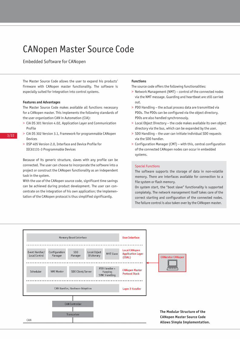
3/22
The Master Source Code allows the user to expand his products’
firmware with CANopen master functionality. The software is
especially suited for integration into control systems.
Features and AdvantagesThe Master Source Code makes available all functions necessary
for a CANopen master. This implements the following standards of
the user organization CAN in Automation (CiA):
> CiA DS 301 Version 4.02, Application Layer and Communication
Profile
> CiA DS 302 Version 3.1, Framework for programmable CANopen
Devices
> DSP 405 Version 2.0, Interface and Device Profile for
IEC61131-3 Programmable Devices
Because of its generic structure, slaves with any profile can be
connected. The user can choose to incorporate the software into a
project or construct the CANopen functionality as an independent
task in the system.
With the use of the CANopen source code, significant time savings
can be achieved during product development. The user can con-
centrate on the integration of his own application; the implemen-
tation of the CANopen protocol is thus simplified significantly.
FunctionsThe source code offers the following functionalities:
> Network Management (NMT) – control of the connected nodes
via the NMT message. Guarding and heartbeat are still carried
out.
> PDO Handling – the actual process data are transmitted via
PDOs. The PDOs can be configured via the object directory.
PDOs are also handled synchronously.
> Local Object Directory – the code makes available its own object
directory via the bus, which can be expanded by the user.
> SDO Handling – the user can initiate individual SDO requests
via the SDO handler.
> Configuration Manager (CMT) – with this, central configuration
of the connected CANopen nodes can occur in embedded
systems.
CANopen Master Source CodeEmbedded Software for CANopen
Special Functions
The software supports the storage of data in non-volatile
memory. There are interfaces available for connection to a
file system or flash memory.
On system start, the “boot slave” functionality is supported
completely. The network management itself takes care of the
correct starting and configuration of the connected nodes.
The failure control is also taken over by the CANopen master.
The Modular Structure of the CANopen Master Source Code Allows Simple Implementation.
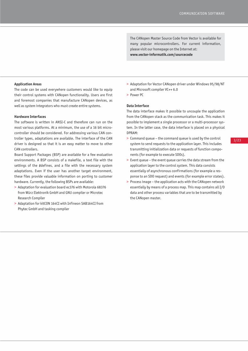
3/23
COMMUNICATION SOFTWARE
Application AreasThe code can be used everywhere customers would like to equip
their control systems with CANopen functionality. Users are first
and foremost companies that manufacture CANopen devices, as
well as system integrators who must create entire systems.
Hardware InterfacesThe software is written in ANSI-C and therefore can run on the
most various platforms. At a minimum, the use of a 16 bit micro-
controller should be considered. For addressing various CAN con-
troller types, adaptations are available. The interface of the CAN
driver is designed so that it is an easy matter to move to other
CAN controllers.
Board Support Packages (BSP) are available for a few evaluation
environments. A BSP consists of a makefile, a text file with the
settings of the #defines, and a file with the necessary system
adaptations. Even if the user has another target environment,
these files provide valuable information on porting to customer
hardware. Currently, the following BSPs are available:
> Adaptation for evaluation board ec376 with Motorola 68376
from Würz Elektronik GmbH and GNU compiler or Microtec
Research Compiler
> Adaptation for kitCON 164CI with Infineon SAB164CI from
Phytec GmbH and tasking compiler
> Adaptation for Vector CANopen driver under Windows 95/98/NT
and Microsoft compiler VC++ 6.0
> Power PC
Data InterfaceThe data interface makes it possible to uncouple the application
from the CANopen stack as the communication task. This makes it
possible to implement a single processor or a multi-processor sys-
tem. In the latter case, the data interface is placed on a physical
DPRAM:
> Command queue – the command queue is used by the control
system to send requests to the application layer. This includes
transmitting initialization data or requests of function compo-
nents (for example to execute SDOs).
> Event queue – the event queue carries the data stream from the
application layer to the control system. This data consists
essentially of asynchronous confirmations (for example a res-
ponse to an SDO request) and events (for example error states).
> Process image – the application acts with the CANopen network
essentially by means of a process map. This map contains all I/O
data and other process variables that are to be transmitted by
the CANopen master.
The CANopen Master Source Code from Vector is available for
many popular microcontrollers. For current information,
please visit our homepage on the Internet at:
www.vector-informatik.com/sourcecode

3/24
Network ManagementThis module assumes responsibility for administering and moni-
toring nodes that are connected in the network. For this to hap-
pen, the nodes that are to be accessed and monitored must be
declared. The corresponding parameters for error monitoring
(guarding and heartbeat) must also be transmitted. This informa-
tion is stored in the local object directory and can then be reque-
sted externally via the bus and internally via the DPRAM. The
monitoring and start of nodes runs largely automatically.
PDO HandlingThe PDO handler has the task of accepting received PDOs from the
slaves and forwarding them to the process map of the data inter-
face. In the other direction, it transmits values from the applica-
tion to the slaves. This can take place cyclically (by SYNC) or it can
be event-driven (by change).
The assignment between PDO and storage of data takes place
exclusively via the local object directory. The application is thus
completely uncoupled from concrete communication tasks.
SDO HandlingThe SDO handler makes it possible for the application to have
access to the object directories of the connected CANopen nodes.
It is possible to transmit data blocks in either direction. The
“expedited download/upload protocol” is used for objects up to a
size of 4 bytes. For objects larger than 4 bytes, the “segmented
download/upload protocol” is used.
The block transfer is also implemented and can be initiated in a
number of ways, one of which is by the user.
It is possible to run multiple SDO transfers in parallel (only for dif-
ferent SDOs).
Local Object DirectoryThe Local Object Directory enables access to the master functions
and to master parameters and variables over the network. This
makes it possible to configure the master over the network or to
operate it through locally available functions (displays or inputs
and outputs). The Configuration Manager is especially activated
this way.
The variables in the object directory can be accessed by the appli-
cation through the corresponding SDO read/write requests by
indicating the own node ID.
3/25
COMMUNICATION SOFTWARE
Configuration Manager (CMT)The Configuration Manager has the task of saving parameter sets
of the CANopen slaves and distributing them at a certain time to
the connected nodes on the network. The time of this distribution
can be determined in the following manner:
> When the master is started, a configuration is performed for all
nodes that have been entered in the list of assigned slaves and
for which a configuration is available.
> If guarding or heartbeat fails, the configuration is initiated
again.
> Initiating the configuration of a specific node at any time by
the application – for example in order to subsequently
configure connected sub-networks.
In this context, the configuration of CANopen devices refers to
setting parameters in their object directory. The parameters in
question are mainly PDO parameters and mapping information.
◆
Support during Integration
Naturally we can also support you during the integration of
the CANopen Master Source Code into your environment. Our
support services range from custom-tailored training solu-
tions to workshops to project work.
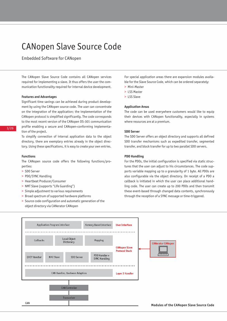
3/26
CANopen Slave Source CodeEmbedded Software for CANopen
The CANopen Slave Source Code contains all CANopen services
required for implementing a slave. It thus offers the user the com-
munication functionality required for internal device development.
Features and AdvantagesSignificant time savings can be achieved during product develop-
ment by using the CANopen source code. The user can concentrate
on the integration of the application; the implementation of the
CANopen protocol is simplified significantly. The code corresponds
to the most recent version of the CANopen DS-301 communication
profile enabling a secure and CANopen-conforming implementa-
tion of the project.
To simplify connection of internal application data to the object
directory, there are exemplary entries already in the object direc-
tory. Using these specifications, it is easy to create your own entries.
FunctionsThe CANopen source code offers the following functions/pro-
perties:
> SDO Server
> PDO/SYNC Handling
> Heartbeat Producer/Consumer
> NMT Slave (supports “Life Guarding”)
> Simple adjustment to various requirements
> Broad spectrum of supported hardware platforms
> Source code configuration and automatic generation of the
object directory via CANerator CANopen
For special application areas there are expansion modules availa-
ble for the Slave Source Code, which can be ordered separately:
> Mini-Master
> LSS Master
> LSS Slave
Application AreasThe code can be used everywhere customers would like to equip
their devices with CANopen functionality, especially in systems
where resources are at a premium.
SDO ServerThe SDO Server offers an object directory and supports all defined
SDO transfer mechanisms such as expedited transfer, segmented
transfer, and block transfer for up to two parallel SDO servers.
PDO HandlingFor the PDOs, the initial configuration is specified via static struc-
tures that the user can adjust to his circumstances. The code sup-
ports variable mapping up to a granularity of 1 byte. All PDOs are
also configurable via the object directory. On receipt of a PDO a
callback is initiated in which the user can place additional hand-
ling code. The user can create up to 200 PDOs and then transmit
these event-based through changed data contents, synchronously
through the reception of a SYNC message or time-triggered.
Modules of the CANopen Slave Source Code

3/27
COMMUNICATION SOFTWARE
NMT SlaveThe code supports both guarding and heartbeat. It is possible to
react to heartbeat messages of other nodes (heartbeat consumer).
This makes it possible to set up highly efficient monitoring mecha-
nisms in a network. User-specific emergency messages can also be
generated.
The code supports an interface for non-volatile storage of parame-
ters. Here it is assumed that the memory is available via a file
system or as flash.
Mini-MasterThe full functionality of a CANopen manager is not required for
many embedded networks. Often, by limiting functionality,
emphasis can be placed on requiring very few resources and the
simplest possible use.
This is the purpose of the add-on Mini-Master. It contains:
> NMT Master – control of the status machine of the NMT slaves to
start the network, for example. Monitoring of nodes by means
of node guarding. Heartbeat monitoring is always a component
of the Slave Source Code.
> SDO Client – the slave can thus also initiate an SDO transfer. This
makes it possible to adjust settings in the object directories of
other nodes and to call up data that is not available through
PDO (e.g. for diagnostic purposes).
> SYNC Producer – This module can be used to periodically send
the SYNC message.
LSS (Layer Setting Services) Among other things, CANopen devices require a setting of baud
rate and node number. Devices without access possibilities via
switches (e.g. watertight sensors) require a setting of these
values via the CAN bus itself. CANopen specifies the LSS (CiA 305)
for this. The necessary services are provided in the form of source
code modules by the LSS Slave and LSS Master add-on modules.
Adaptation of the CodeBefore the code is translated, the user can specify the qualities to
be supported allowing the code to be used even on systems with
very limited resources. The adaptation occurs via the #define
instructions that are set in a configuration file. By using the
CANerator tools (sold separately), this adaptation is simplified
significantly.
Local Object DirectoryThe object directory of the Slave Source Code can easily be expan-
ded by the user. For this, appropriate entries must be added to the
C files. Such an object directory contains the object’s attributes
and a pointer to the actual memory location. For each object it is
possible to initiate callback functions with user-defined function-
ality when reading or writing. Thus, for example, an area test can
be implemented when writing an object. With the aid of the CANopen
CANerator, this object directory can be created automatically.
For additional functional details, please refer to the CANopen
CANerator product information.
Adaptation to a Target HardwareTo use the Slave Source Code on a microcontroller platform, first
an adaptation is always necessary to abstract the CAN controller
and the specific timer and interrupt system. Of course, the rele-
vant compiler is also considered here. Vector offers prepared adap-
tations for many platform combinations.
◆
The CANopen Slave Source Code by Vector is available for
many popular microcontrollers. For current information,
please visit our homepage on the Internet at:
www.vector.com/sourcecode
Support during Integration
We can also support you during the integration of the
CANopen Slave Source Code into your environment. Our sup-
port services range from custom-tailored training solutions
to workshops to project work.
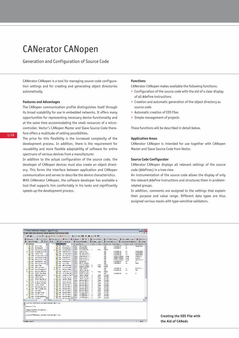
3/28
Creating the EDS File with the Aid of CANeds
CANerator CANopen Generation and Configuration of Source Code
CANerator CANopen is a tool for managing source code configura-
tion settings and for creating and generating object directories
automatically.
Features and AdvantagesThe CANopen communication profile distinguishes itself through
its broad scalability for use in embedded networks. It offers many
opportunities for representing necessary device functionality and
at the same time accommodating the small resources of a micro-
controller. Vector’s CANopen Master and Slave Source Code there-
fore offers a multitude of setting possibilities.
The price for this flexibility is the increased complexity of the
development process. In addition, there is the requirement for
reusability and more flexible adaptability of software for entire
spectrums of various devices from a manufacturer.
In addition to the actual configuration of the source code, the
developer of CANopen devices must also create an object direct-
ory. This forms the interface between application and CANopen
communication and serves to describe the device characteristics.
With CANerator CANopen, the software developer has available a
tool that supports him comfortably in his tasks and significantly
speeds up the development process.
FunctionsCANerator CANopen makes available the following functions:
> Configuration of the source code with the aid of a clear display
of all #define instructions
> Creation and automatic generation of the object directory as
source code
> Automatic creation of EDS files
> Simple management of projects
These functions will be described in detail below.
Application AreasCANerator CANopen is intended for use together with CANopen
Master and Slave Source Code from Vector.
Source Code ConfiguratorCANerator CANopen displays all relevant settings of the source
code (#defines) in a tree view.
An instrumentation of the source code allows the display of only
the relevant #define instructions and structures them in problem-
related groups.
In addition, comments are assigned to the settings that explain
their purpose and value range. Different data types are thus
assigned various masks with type-sensitive validators.
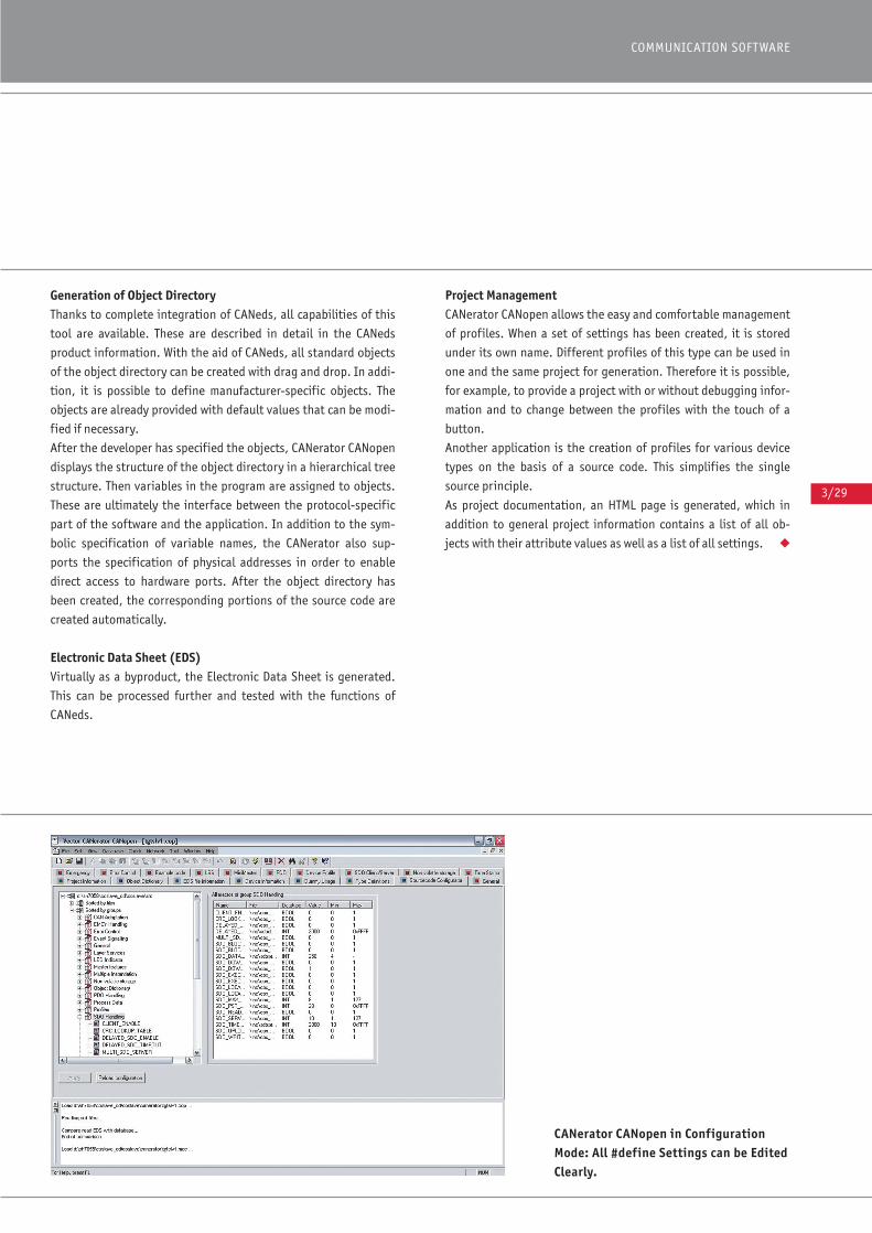
3/29
COMMUNICATION SOFTWARE
CANerator CANopen in ConfigurationMode: All #define Settings can be EditedClearly.
Generation of Object DirectoryThanks to complete integration of CANeds, all capabilities of this
tool are available. These are described in detail in the CANeds
product information. With the aid of CANeds, all standard objects
of the object directory can be created with drag and drop. In addi-
tion, it is possible to define manufacturer-specific objects. The
objects are already provided with default values that can be modi-
fied if necessary.
After the developer has specified the objects, CANerator CANopen
displays the structure of the object directory in a hierarchical tree
structure. Then variables in the program are assigned to objects.
These are ultimately the interface between the protocol-specific
part of the software and the application. In addition to the sym-
bolic specification of variable names, the CANerator also sup-
ports the specification of physical addresses in order to enable
direct access to hardware ports. After the object directory has
been created, the corresponding portions of the source code are
created automatically.
Electronic Data Sheet (EDS) Virtually as a byproduct, the Electronic Data Sheet is generated.
This can be processed further and tested with the functions of
CANeds.
Project ManagementCANerator CANopen allows the easy and comfortable management
of profiles. When a set of settings has been created, it is stored
under its own name. Different profiles of this type can be used in
one and the same project for generation. Therefore it is possible,
for example, to provide a project with or without debugging infor-
mation and to change between the profiles with the touch of a
button.
Another application is the creation of profiles for various device
types on the basis of a source code. This simplifies the single
source principle.
As project documentation, an HTML page is generated, which in
addition to general project information contains a list of all ob-
jects with their attribute values as well as a list of all settings. ◆
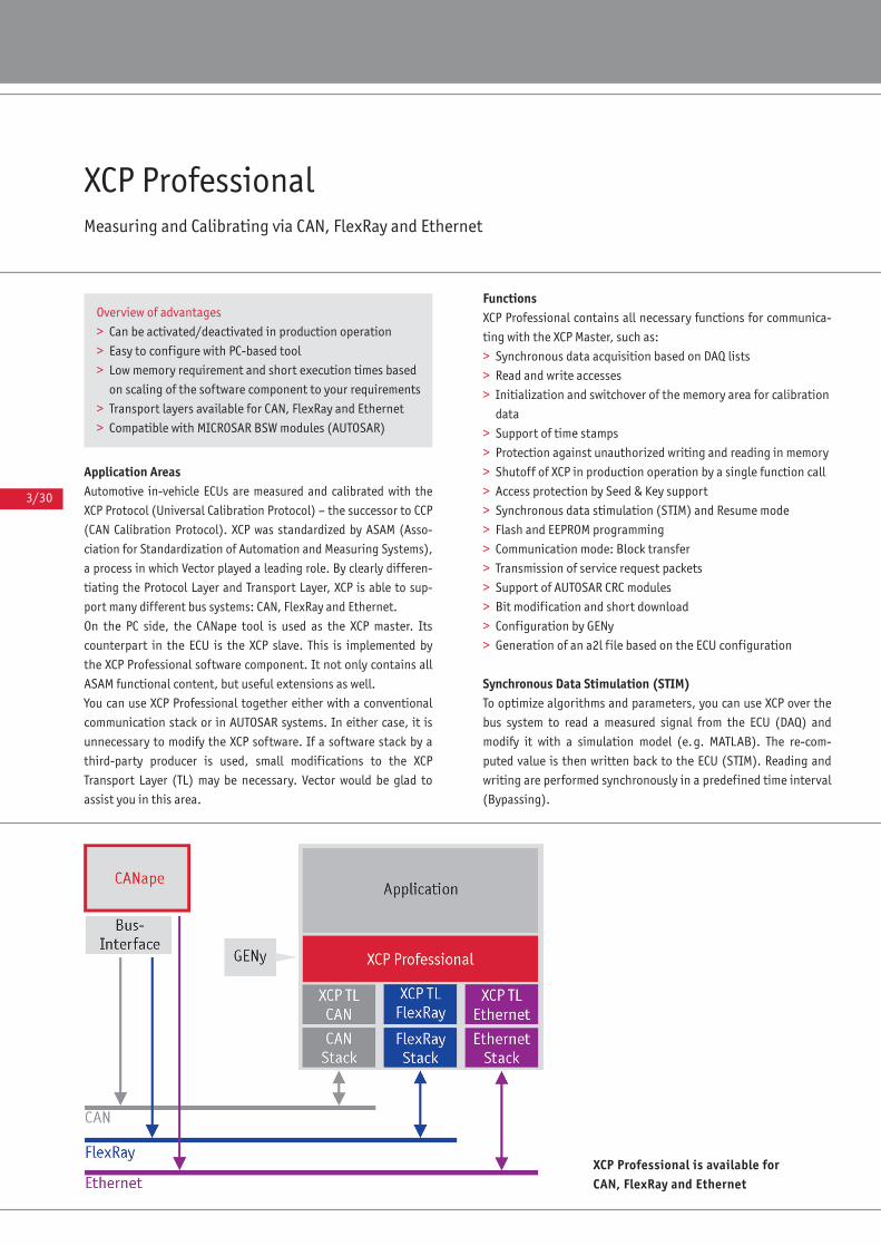
3/30
XCP ProfessionalMeasuring and Calibrating via CAN, FlexRay and Ethernet
Application AreasAutomotive in-vehicle ECUs are measured and calibrated with the
XCP Protocol (Universal Calibration Protocol) – the successor to CCP
(CAN Calibration Protocol). XCP was standardized by ASAM (Asso-
ciation for Standardization of Automation and Measuring Systems),
a process in which Vector played a leading role. By clearly differen-
tiating the Protocol Layer and Transport Layer, XCP is able to sup-
port many different bus systems: CAN, FlexRay and Ethernet.
On the PC side, the CANape tool is used as the XCP master. Its
counterpart in the ECU is the XCP slave. This is implemented by
the XCP Professional software component. It not only contains all
ASAM functional content, but useful extensions as well.
You can use XCP Professional together either with a conventional
communication stack or in AUTOSAR systems. In either case, it is
unnecessary to modify the XCP software. If a software stack by a
third-party producer is used, small modifications to the XCP
Transport Layer (TL) may be necessary. Vector would be glad to
assist you in this area.
FunctionsXCP Professional contains all necessary functions for communica-
ting with the XCP Master, such as:
> Synchronous data acquisition based on DAQ lists
> Read and write accesses
> Initialization and switchover of the memory area for calibration
data
> Support of time stamps
> Protection against unauthorized writing and reading in memory
> Shutoff of XCP in production operation by a single function call
> Access protection by Seed & Key support
> Synchronous data stimulation (STIM) and Resume mode
> Flash and EEPROM programming
> Communication mode: Block transfer
> Transmission of service request packets
> Support of AUTOSAR CRC modules
> Bit modification and short download
> Configuration by GENy
> Generation of an a2l file based on the ECU configuration
Synchronous Data Stimulation (STIM)To optimize algorithms and parameters, you can use XCP over the
bus system to read a measured signal from the ECU (DAQ) and
modify it with a simulation model (e.g. MATLAB). The re-com-
puted value is then written back to the ECU (STIM). Reading and
writing are performed synchronously in a predefined time interval
(Bypassing).
Overview of advantages
> Can be activated/deactivated in production operation
> Easy to configure with PC-based tool
> Low memory requirement and short execution times based
on scaling of the software component to your requirements
> Transport layers available for CAN, FlexRay and Ethernet
> Compatible with MICROSAR BSW modules (AUTOSAR)
XCP Professional is available forCAN, FlexRay and Ethernet
3/31
COMMUNICATION SOFTWARE
Resume ModeThe Resume mode permits cold-start measurements, e.g. to check
ECU behavior in the wakeup phase. This involves activating the
XCP stored in the flash memory immediately after a cold-start –
even before the application starts. Sending of the measured
values begins automatically, and they can be logged for later eval-
uation.
Flash and EEPROM Programming The Vector XCP component is not only able to store measured
values in RAM, but also in flash or EEPROM memory. To do this,
XCP executes callback functions in which the application could
activate the flash algorithms, for example. This gives you the
option of individually adapting the algorithms to the flash or
EEPROM memory being used.
Communication Mode: Block TransferBlock Transfer lets you transfer large quantities of data. This func-
tionality is comparable to that of a transport protocol. The sender
segments the data, and the receiver re-assembles them in the cor-
rect sequence.
Transmission of Service Request PacketsService request packets let you transmit lines of text. They are
stored in program code, and when the program section is exe-
cuted they are sent to the XCP master where they are displayed.
This function is very useful primarily during system development
and in debugging.
Configuration XCP Professional is configured with the PC-based GENy configura-
tion tool. Compiler switches may be used to deactivate unneeded
functions, and this reduces memory loading. When XCP transmis-
sion is started, the list of supported functions is communicated to
the XCP master via the XCP plug-and-play mechanism. ◆
Training
In the framework of our training program, we can offer you
various training events and workshops for XCP in our class-
rooms or at your business site.
For more information on individual training events and dates
on the Internet go to: www.vector-academy.com
CANape as XCP Master
CANape, the all-round tool for measurement, calibration and
diagnostics of ECUs, is the XCP master, while the ECU acts as the
XCP slave. The XCP slave allows CANape to access the measured
signals and calibration parameters in the ECU with the help of
an ECU description file. Values can be displayed or edited in
physical units.
The key properties of CANape related to measurement and cali-
bration are:
> Time-synchronous real-time acquisition and visualization of
internal ECU signals with XCP/CCP, of signals from CAN, LIN
and FlexRay buses and from external measurement equipment
> Online calibration via XCP/CCP, real-time stimulation via XCP
and offline calibration
> Flash programming of the ECU via XCP/CCP or the diagnostic
protocol
> Rapid prototyping for functional development by bypassing a
MATLAB/Simulink model with the help of CANape
Additional information can be found in the “ECU Calibration”
product catalog.
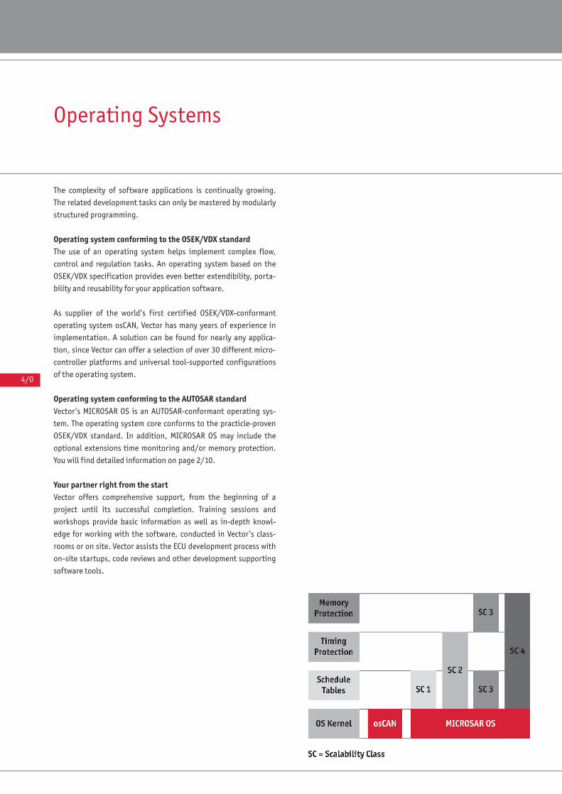
4/0
Operating Systems
The complexity of software applications is continually growing.
The related development tasks can only be mastered by modularly
structured programming.
Operating system conforming to the OSEK/VDX standardThe use of an operating system helps implement complex flow,
control and regulation tasks. An operating system based on the
OSEK/VDX specification provides even better extendibility, porta-
bility and reusability for your application software.
As supplier of the world’s first certified OSEK/VDX-conformant
operating system osCAN, Vector has many years of experience in
implementation. A solution can be found for nearly any applica-
tion, since Vector can offer a selection of over 30 different micro-
controller platforms and universal tool-supported configurations
of the operating system.
Operating system conforming to the AUTOSAR standardVector’s MICROSAR OS is an AUTOSAR-conformant operating sys-
tem. The operating system core conforms to the practicle-proven
OSEK/VDX standard. In addition, MICROSAR OS may include the
optional extensions time monitoring and/or memory protection.
You will find detailed information on page 2/10.
Your partner right from the startVector offers comprehensive support, from the beginning of a
project until its successful completion. Training sessions and
workshops provide basic information as well as in-depth knowl-
edge for working with the software, conducted in Vector’s class-
rooms or on site. Vector assists the ECU development process with
on-site startups, code reviews and other development supporting
software tools.
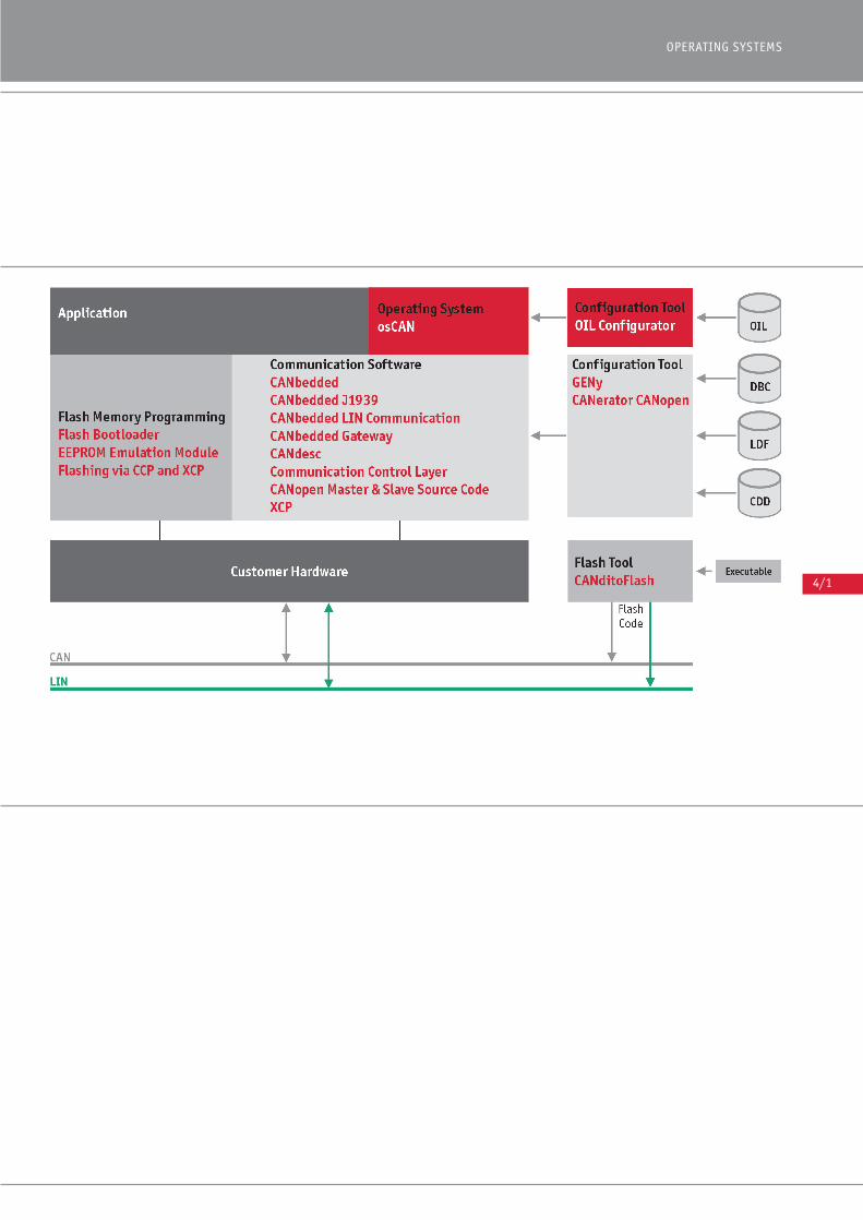
4/1
OPERATING SYSTEMS
4/2
osCANThe real-time operating system based on the OSEK/VDX standard
osCAN is a preemptive real-time multitasking operating system
with properties optimized for use on microcontrollers. Vector’s
many years of experience in developing operating systems and
drivers has made osCAN a small and robust operating system core.
It is certified to OSEK/VDX specification 2.2. This open standard
of the automotive industry provides a foundation for long-term
stability and availability.
Application AreasDue to its static operating system architecture, osCAN is small and
fast, and its use is beneficial wherever resources such as memory
and processing time are in short supply. osCAN is especially ideal
when extremely short boot times are necessary.
FunctionsAs a fully preemptive multitasking operating system, osCAN offers
priority-driven task management and a wide variety of synchro-
nization mechanisms. It can generate cyclic and singular time
intervals as well as behave in an event-driven way. Its flexible
interrupt strategy makes it possible to use system services even
within interrupt service routines.
In addition to functions defined in the standard, osCAN offers:
> Monitoring of stack utilization at runtime
> Internal tracing of system calls
> Extended error checking at runtime
> Clear and concise documentation of the configuration in HTML
With the optional High Resolution Timer, you can implement reso-
lutions higher than 1ms for the timers, without simultaneously
increasing interrupt load. Depending on the controller, resolu-
tions in the microseconds range are possible.
Overview of advantages
> Small, fast and resource-saving operating system core
> Short boot times
> Stack monitoring at runtime (deactivatable)
> Internal fault trace (deactivatable)
> Component management for integration of sub-projects
> Supplied as source code
> Quality process fulfills SPICE Level 3
> Graphic configuration tool for easy configuration of the
operating system
> Simplified execution time analysis of osCAN applications by
supplied TimingAnalyzer
> Available for many 8, 16, 32 and 64 bit microcontrollers
4/3
OPERATING SYSTEMS
Configuration An easy-to-use graphic configuration tool lets you define all oper-
ating system resources before compiling. To assure portability,
the configuration is saved in the standardized OIL format (OSEK
Implementation Language).
The configuration tool offers component management, which lets
you implement sub-applications simultaneously in parallel pro-
cesses. Next, the sub-applications are integrate into a total appli-
cation. This enables short development times and spatially sepa-
rate developments.
Properties:
> Easy to operate graphic user interface
> Automatic checking for completeness and consistency
> Convenient system scaling
> Component management
> ORTI support
Training
In the framework of our training program, we offer various
training events and workshops for osCAN in our classrooms
as well as at the business sites of our customers.
For more information on individual training events and dates
please visit: www.vector-academy.com
Scope of Delivery
> Operating system core as source code
> Graphic configuration tool (OIL) for Windows NT/2000/XP/
Vista/Windows 7
> Instruction line based generator
> Documentation
> Sample programs
> TimingAnalyzer
osCAN conforms to OSEK/VDX specifications
> OSEK/VDX-OS 2.2
> OSEK/VDX-OIL 2.3
> OSEK/VDX-COM 2.2.2
> All conformity classes (BCC1, BCC2, ECC1, ECC2, CCCA,
CCCB)
> Size: 1–10 kB ROM, depending on platform and
configuration
Availability
The real-time operating system osCAN from Vector is availa-
ble for many commonly used 8, 16 and 32 bit microcontrol-
lers. For more information on the Internet go to:
www.vector.com/oscan
Additional Services
Vector offers you worldwide support related to OSEK/VDX:
> Training courses
> Design consultation
> Customer-specific implementations
> Hotline
> Software maintenance
The scope and form of all services are aligned to your wishes
and needs.
Related Vector products:
> CANoe osCAN Library
> TimingAnalyzer
> High Resolution Timer
Complete solution from Vector
Vector provides you a completely tuned solution for devel-
oping ECUs. Along with the operating system, you get proto-
cols and drivers for CAN, LIN or FlexRay. For more detailed
information, please refer to the relevant datasheets.
Supporting ToolsThe TimingAnalyzer design assistant simulates and computes
task execution times for you. The analysis is performed for each
task and each interrupt with the following parameters: Priority,
period, execution time and deadline. The graphic user interface
offers clear and concise visualization of system behavior.
With the help of the CANoe osCAN Library, your application can
be compiled into a DLL and integrated in a network simulation
under CANoe. This allows the application to be tested even before
the availability of first hardware prototypes.
Many emulators already offer the option of observing application
behavior on the operating system services level (OSEK Aware-
ness). osCAN supports the ORTI interface required for this.
Some UML and SDL modeling tools give you the option of configu-
ring models for use with an OSEK/VDX operating system. This is
possible, for example, with:
> MATLAB/Simulink from Mathworks
> TargetLink from dSPACE
◆

4/4
High Resolution TimerImprove performance with high-precision timers for operating systems
An important property of operating systems is the precision of
alarms; this in turn affects the resulting interrupt load. The alarm
mechanism of an OSEK/VDX or AUTOSAR operating system is based
on counters which are incremented by either software or hard-
ware timers. When a counter reaches a preset alarm value, a pre-
defined action is executed. The typical time resolution of such
timers is 1 ms.
If timer resolutions with a higher precision than 1 ms are required,
the High Resolution Timer mechanism can achieve these enhan-
ced precisions without simultaneously increasing interrupt load.
Resolutions in the microsecond range are possible depending on
the controller used.
Features and advantages The High Resolution Timer for the osCAN and MICROSAR OS oper-
ating systems permits high-precision alarms with low system
interrupt load (depending on hardware). An interrupt is only
triggered when an alarm actually becomes due.
The precision of the alarm time depends only on the resolution
and clock frequency of the hardware timer. It may range from
100 ns to 100 μs depending on the microcontroller.
Functions“Collective” processing of several consecutive alarms can be con-
trolled by defining a minimum interval between timer interrupts.
This reduces interrupt load, especially when several alarms with
similar intervals expire almost simultaneously.
Application areasThe High Resolution Timer is designed for applications
requiring high-precision timers but in which additional interrupt
loads are unacceptable.
Hardware requirementsThe High Resolution Timer can be used on all microcontrollers
which have a free-running timer. The timer must also be able to
trigger an interrupt when its value matches a user-definable com-
pare value (compare-match). The clock speed at which the hard-
ware timer is operated should be adjustable so that the desired
level of accuracy is achieved.
Configuration The High Resolution Timer is configured using the configuration
tool for the Vector operating systems. This tool is used to adjust
the prescalers according to the clock frequency of the microcon-
troller. ◆
Alarms and Tasks
4/5
OPERATING SYSTEMS
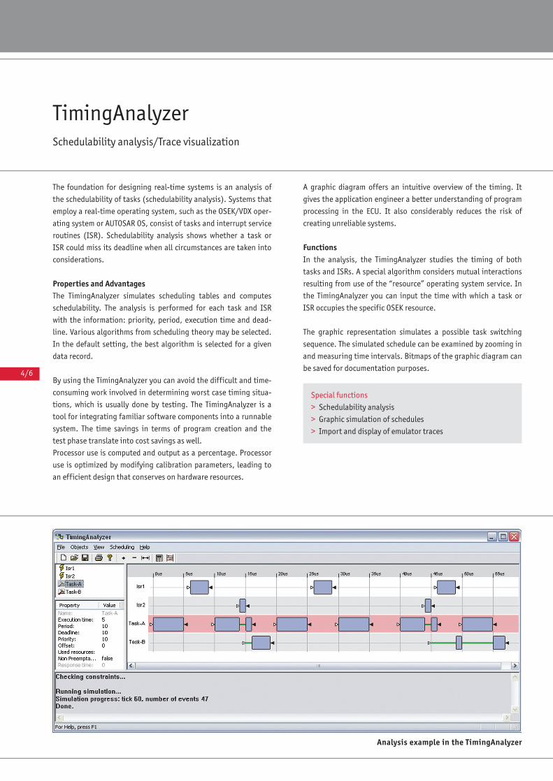
4/6
TimingAnalyzerSchedulability analysis/Trace visualization
The foundation for designing real-time systems is an analysis of
the schedulability of tasks (schedulability analysis). Systems that
employ a real-time operating system, such as the OSEK/VDX oper-
ating system or AUTOSAR OS, consist of tasks and interrupt service
routines (ISR). Schedulability analysis shows whether a task or
ISR could miss its deadline when all circumstances are taken into
considerations.
Properties and AdvantagesThe TimingAnalyzer simulates scheduling tables and computes
schedulability. The analysis is performed for each task and ISR
with the information: priority, period, execution time and dead-
line. Various algorithms from scheduling theory may be selected.
In the default setting, the best algorithm is selected for a given
data record.
By using the TimingAnalyzer you can avoid the difficult and time-
consuming work involved in determining worst case timing situa-
tions, which is usually done by testing. The TimingAnalyzer is a
tool for integrating familiar software components into a runnable
system. The time savings in terms of program creation and the
test phase translate into cost savings as well.
Processor use is computed and output as a percentage. Processor
use is optimized by modifying calibration parameters, leading to
an efficient design that conserves on hardware resources.
A graphic diagram offers an intuitive overview of the timing. It
gives the application engineer a better understanding of program
processing in the ECU. It also considerably reduces the risk of
creating unreliable systems.
FunctionsIn the analysis, the TimingAnalyzer studies the timing of both
tasks and ISRs. A special algorithm considers mutual interactions
resulting from use of the “resource” operating system service. In
the TimingAnalyzer you can input the time with which a task or
ISR occupies the specific OSEK resource.
The graphic representation simulates a possible task switching
sequence. The simulated schedule can be examined by zooming in
and measuring time intervals. Bitmaps of the graphic diagram can
be saved for documentation purposes.
Analysis example in the TimingAnalyzer
Special functions
> Schedulability analysis
> Graphic simulation of schedules
> Import and display of emulator traces
4/7
OPERATING SYSTEMS
Data ImportBesides manual data input, the data may also be read-in from the
configuration file of the operating system. This simplifies hand-
ling, since data input and calling of the TimingAnalyzer are per-
formed directly in the configuration tool.
Application AreasThe TimingAnalyzer is an efficient tool for all development
departments that use real-time operating systems. Special atten-
tion was given to supporting OSEK/VDX and AUTOSAR real-time
operating systems and their applications.
Scope of Delivery> Graphic analysis tool for Windows NT/2000/XP/
Vista/Windows 7
> Documentation in electronic form
> Sample files ◆
Availability
The TimingAnalyzer is available in combination with the
OSEK/VDX-conformant operating system osCAN as well as the
AUTOSAR-conformant MICROSAR OS.

EMBEDDED SOFTWARE
More Information: www.vector.com/contact
V2.0
201
0-05
Controller Compiler
Altera
Excalibur Green Hills
NIOS II GNU, TaskingVX
ARM
ARM7-TDMI Green Hills
Atmel
AT91 Green Hills
AVR32 IAR
Freescale
68HC08 Cosmic
68HC12, S12 Cosmic, IAR, Metrowerks
MAC71xx Green Hills
Mcore DIABDATA Wind River
MPC55x, MPC56x DIABDATA Wind River, Green Hills, Metrowerks
MPC55xx, MPC56xx DIABDATA Wind River, Green Hills, Metrowerks
S12X Cosmic, Metrowerks
Fujitsu
16FX Fujitsu
16LX Fujitsu
FR30, FR50, FR60 Fujitsu
MB86 Green Hills
Infineon
C167 Keil, Tasking, TaskingVX
Tricore Tasking
XC16x Keil, Tasking, TaskingVX
XC2000 TaskingVX
Intel
PXA27x Green Hills
Microchip
dsPIC30 Microchip
PIC18 Microchip
PIC24 Microchip
Controller Compiler
Micronas
CDC32xxG Green Hills
NXP
LPC2XXX Green Hills
SAF7780 ARM, Green Hills
SJA20xx Green Hills
OKI
ML67 Green Hills, IAR
ML665S OKI
Renesas Electronics (NEC/Renesas)
78kO IAR
H8 tiny Renesas
H8S Renesas
H8SX Renesas
M16C Renesas, IAR, Tasking
M32C Renesas, IAR
M32R Renesas, GAIO
R32C Renesas, IAR
SH2 Renesas, GAIO
V850 Green Hills, IAR
STmicroelectronics
ST10 Keil, Tasking
Texas Instruments
MSP 430 IAR
TMS 320 Texas Instruments
TMS 470 Texas Instruments, Green Hills
TMS 570 Texas Instruments
Toshiba
TLCS-900 Toshiba
TX19, TX39, TX49 Green Hills
TX19A Toshiba
Vector
CANoe osCAN Emulation Microsoft VisualC
Wide Availability of osCAN Supported Microcontrollers and Compilers

EMBEDDED SOFTWARE
More Information: www.vector.com/contact
5/0
Flash Memory Programming
Today, systems for downloading software to ECUs are used in all
phases of ECU development. Vector offers a number of software
solutions to meet various requirements:
> Flash Bootloader for CAN, LIN, FlexRay, MOST and Ethernet
> Flashing via CCP/XCP
> Option for the Flash Bootloader: Security component
> Option for the Flash Bootloader: Data compression
> PC-based flash tool
Flash BootloaderThe Flash Bootloader lets you program ECUs with new software
within an in-vehicle network. In particular, when the ECU is
mounted at a hard to access location in the vehicle, the Flash
Bootloader offers the advantage of updating ECU software with-
out needing to remove the ECU. This results in the following capa-
bilities:
> Reprogramming during the development phase
> End-of-line programming
> Software updating in the Service area (After Sales)
Reprogramming is performed via CAN, FlexRay, MOST or Ethernet
utilizing a diagnostic protocol (UDS or KWP2000). A special LIN
Flash Bootloader is available for LIN Slave ECUs.
Programming via XCP/CCPThe use of XCP or CCP is an alternative to reprogramming with the
Flash Bootloader. This variant is primarily used to optimize ECU
parameters. Since XCP/CCP programming is generally used in the
development phase, unlike the Flash Bootloader, security aspects
play a subordinate role here.
Security componentECUs can only be reprogrammed if the ECU has been unlocked
beforehand with the help of a request/response (Seed/Key)
method. As soon as the ECU is unlocked, it can also be reprogram-
med with ECU software, even if it does not originate from the
automotive OEM.
Since the Request/Response method provides inadequate protec-
tion from a technical security perspective, special cryptographic
methods are used in security-critical ECUs. Security requirements
related to software manipulation pose the greatest challenge to
the software. This optional extension of the Flash Bootloader that
adds a security component provides maximum security and the
flexibility to set the security level required by the automotive
OEM.
Data compressionAutomotive electronics is continuously becoming more complex,
and so it requires more extensive software. Suitable data com-
pression methods can be used to transport the increasing amo-
unts of data more quickly on data buses; they reduce transmission
times drastically. Vector offers optimized solutions for the Flash
Bootloader and flash tools.
Flash toolsDifferent data and diagnostic formats are used by different auto-
motive OEMs for programming ECUs. Meanwhile, ODX and ODX-F
have become established at some automotive OEMs as a standard
data format for ECU programming.
To master the many different data and diagnostic exchange for-
mats, Vector offers authoring and flash tools for specific use
cases in its CANdelaFlash and CANditoFlash products.
Flashing CANopen ECUsVector also offers Flash Bootloaders for the special requirements
involved in flashing CANopen ECUs. Vector can adapt them to your
platform in the context of project work.
EEPROM Emulation Module (EepM)The EEPROM Emulation Module (EepM) lets you efficiently store
nonvolatile data of any desired length in program or data flash
memory. The module is called directly by the application. To save
on resources, the module can be used by either the application or
the Flash Bootloader.
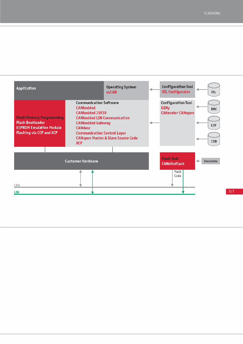
5/1
FLASHING
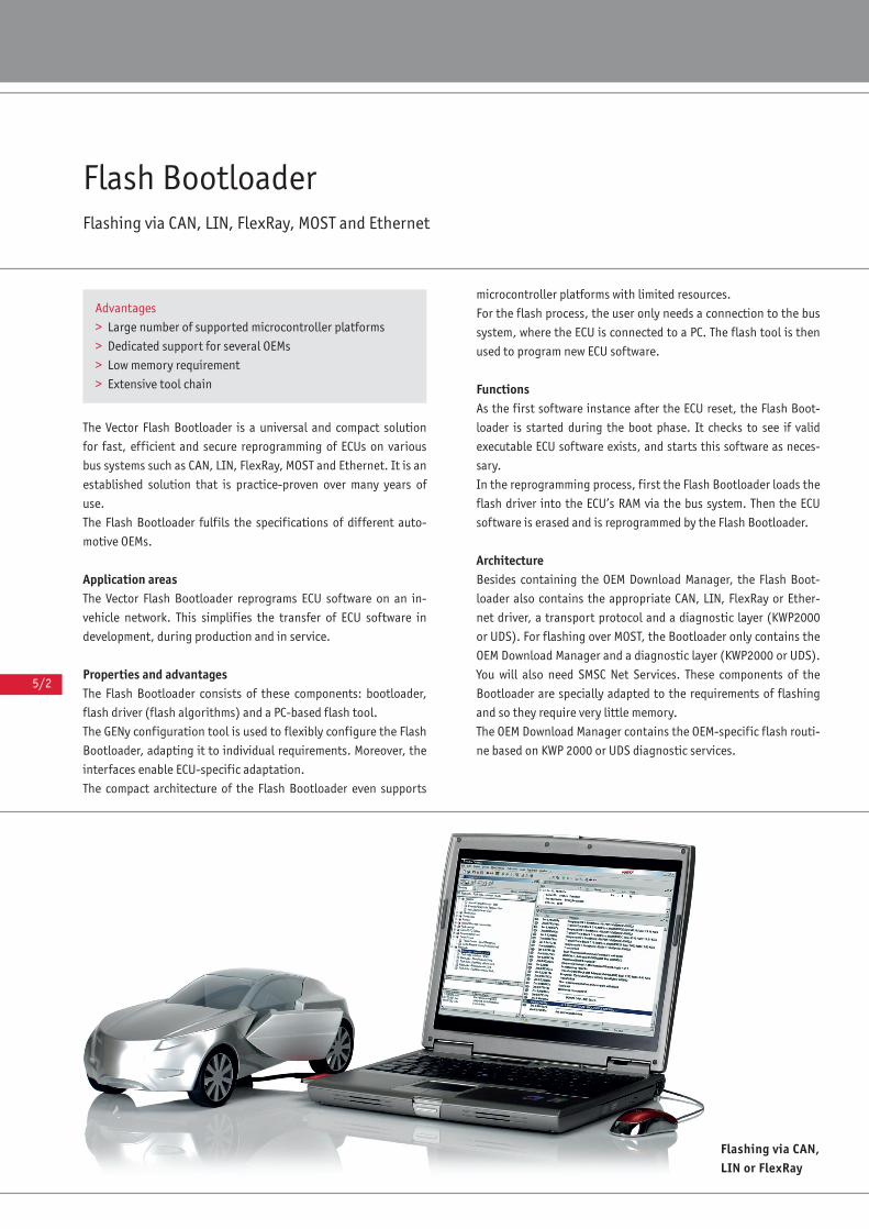
5/2
Flash BootloaderFlashing via CAN, LIN, FlexRay, MOST and Ethernet
The Vector Flash Bootloader is a universal and compact solution
for fast, efficient and secure reprogramming of ECUs on various
bus systems such as CAN, LIN, FlexRay, MOST and Ethernet. It is an
established solution that is practice-proven over many years of
use.
The Flash Bootloader fulfils the specifications of different auto-
motive OEMs.
Application areasThe Vector Flash Bootloader reprograms ECU software on an in-
vehicle network. This simplifies the transfer of ECU software in
development, during production and in service.
Properties and advantagesThe Flash Bootloader consists of these components: bootloader,
flash driver (flash algorithms) and a PC-based flash tool.
The GENy configuration tool is used to flexibly configure the Flash
Bootloader, adapting it to individual requirements. Moreover, the
interfaces enable ECU-specific adaptation.
The compact architecture of the Flash Bootloader even supports
microcontroller platforms with limited resources.
For the flash process, the user only needs a connection to the bus
system, where the ECU is connected to a PC. The flash tool is then
used to program new ECU software.
FunctionsAs the first software instance after the ECU reset, the Flash Boot-
loader is started during the boot phase. It checks to see if valid
executable ECU software exists, and starts this software as neces-
sary.
In the reprogramming process, first the Flash Bootloader loads the
flash driver into the ECU’s RAM via the bus system. Then the ECU
software is erased and is reprogrammed by the Flash Bootloader.
ArchitectureBesides containing the OEM Download Manager, the Flash Boot-
loader also contains the appropriate CAN, LIN, FlexRay or Ether-
net driver, a transport protocol and a diagnostic layer (KWP2000
or UDS). For flashing over MOST, the Bootloader only contains the
OEM Download Manager and a diagnostic layer (KWP2000 or UDS).
You will also need SMSC Net Services. These components of the
Bootloader are specially adapted to the requirements of flashing
and so they require very little memory.
The OEM Download Manager contains the OEM-specific flash routi-
ne based on KWP 2000 or UDS diagnostic services.
Flashing via CAN,LIN or FlexRay
Advantages
> Large number of supported microcontroller platforms
> Dedicated support for several OEMs
> Low memory requirement
> Extensive tool chain
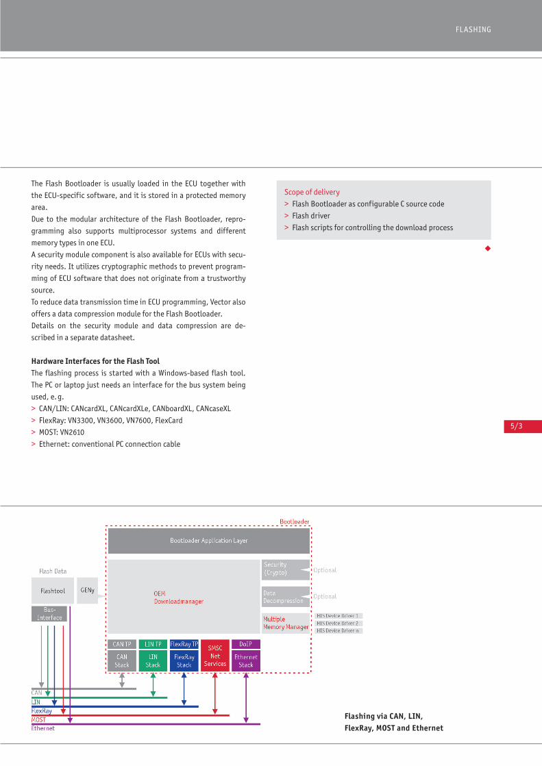
5/3
FLASHING
The Flash Bootloader is usually loaded in the ECU together with
the ECU-specific software, and it is stored in a protected memory
area.
Due to the modular architecture of the Flash Bootloader, repro-
gramming also supports multiprocessor systems and different
memory types in one ECU.
A security module component is also available for ECUs with secu-
rity needs. It utilizes cryptographic methods to prevent program-
ming of ECU software that does not originate from a trustworthy
source.
To reduce data transmission time in ECU programming, Vector also
offers a data compression module for the Flash Bootloader.
Details on the security module and data compression are de-
scribed in a separate datasheet.
Hardware Interfaces for the Flash ToolThe flashing process is started with a Windows-based flash tool.
The PC or laptop just needs an interface for the bus system being
used, e.g.
> CAN/LIN: CANcardXL, CANcardXLe, CANboardXL, CANcaseXL
> FlexRay: VN3300, VN3600, VN7600, FlexCard
> MOST: VN2610
> Ethernet: conventional PC connection cable
◆
Flashing via CAN, LIN, FlexRay, MOST and Ethernet
Scope of delivery
> Flash Bootloader as configurable C source code
> Flash driver
> Flash scripts for controlling the download process
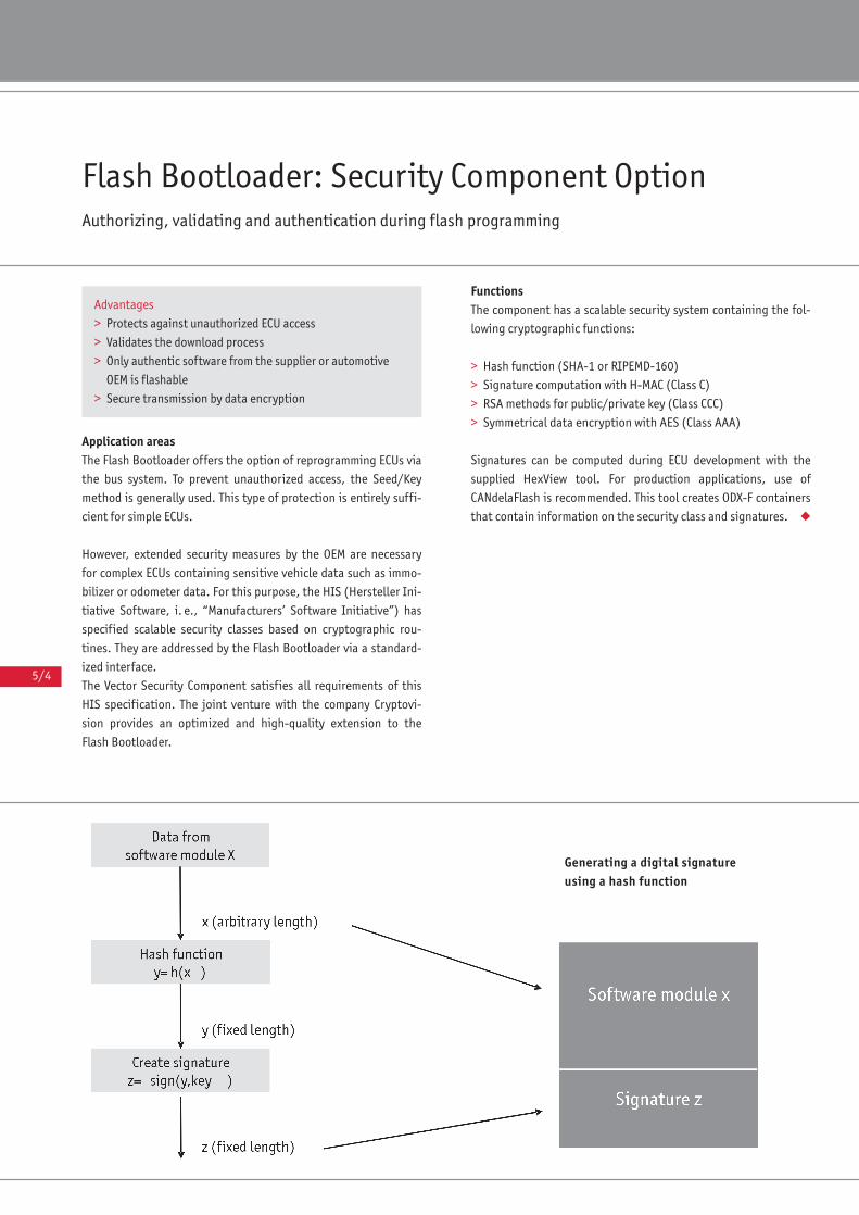
5/4
Flash Bootloader: Security Component OptionAuthorizing, validating and authentication during flash programming
Application areasThe Flash Bootloader offers the option of reprogramming ECUs via
the bus system. To prevent unauthorized access, the Seed/Key
method is generally used. This type of protection is entirely suffi-
cient for simple ECUs.
However, extended security measures by the OEM are necessary
for complex ECUs containing sensitive vehicle data such as immo-
bilizer or odometer data. For this purpose, the HIS (Hersteller Ini-
tiative Software, i. e., “Manufacturers’ Software Initiative”) has
specified scalable security classes based on cryptographic rou-
tines. They are addressed by the Flash Bootloader via a standard-
ized interface.
The Vector Security Component satisfies all requirements of this
HIS specification. The joint venture with the company Cryptovi-
sion provides an optimized and high-quality extension to the
Flash Bootloader.
FunctionsThe component has a scalable security system containing the fol-
lowing cryptographic functions:
> Hash function (SHA-1 or RIPEMD-160)
> Signature computation with H-MAC (Class C)
> RSA methods for public/private key (Class CCC)
> Symmetrical data encryption with AES (Class AAA)
Signatures can be computed during ECU development with the
supplied HexView tool. For production applications, use of
CANdelaFlash is recommended. This tool creates ODX-F containers
that contain information on the security class and signatures. ◆
Advantages
> Protects against unauthorized ECU access
> Validates the download process
> Only authentic software from the supplier or automotive
OEM is flashable
> Secure transmission by data encryption
Generating a digital signatureusing a hash function
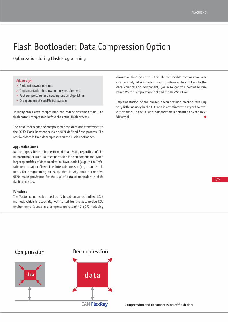
5/5
FLASHING
In many cases data compression can reduce download time. The
flash data is compressed before the actual flash process.
The flash tool reads the compressed flash data and transfers it to
the ECU’s Flash Bootloader via an OEM-defined flash process. The
received data is then decompressed in the Flash Bootloader.
Application areasData compression can be performed in all ECUs, regardless of the
microcontroller used. Data compression is an important tool when
larger quantities of data need to be downloaded (e.g. in the Info-
tainment area) or fixed time intervals are set (e.g. max. 3 mi-
nutes for programming an ECU). That is why most automotive
OEMs make provisions for the use of data compression in their
flash processes.
FunctionsThe Vector compression method is based on an optimized LZ77
method, which is especially well suited for the automotive ECU
environment. It enables a compression rate of 40–60 %, reducing
download time by up to 50 %. The achievable compression rate
can be analyzed and determined in advance. In addition to the
data compression component, you also get the command line
based Vector Compression Tool and the HexView tool.
Implementation of the chosen decompression method takes up
very little memory in the ECU and is optimized with regard to exe-
cution time. On the PC side, compression is performed by the Hex-
View tool. ◆
Flash Bootloader: Data Compression OptionOptimization during Flash Programming
Advantages
> Reduced download times
> Implementation has low memory requirement
> Fast compression and decompression algorithms
> Independent of specific bus system
Compression and decompression of flash data

5/6
EEPROM Emulation Module (EepM)EEPROM Emulation in Flash Memory
In recent years, flash memory has become more cost-effective
and faster than conventional EEPROMs. New microcontrollers are
often offered without EEPROM memory and just have a larger
internal flash memory. Since writing to flash memory, unlike
EEPROMs, is not by the byte but by the page, it is only possible to
achieve optimized utilization of the flash memory with the help of
an EEPROM emulation.
Application AreasFlash memory cannot be erased or written in the same way as con-
ventional EEPROMs. EEPROM emulation in flash memory makes it
possible for an application to store changed nonvolatile data in a
flash memory, just as in a conventional EEPROM.
FunctionsThe Vector EEPROM Emulation Module (EepM) manages predefined
flash areas by taking all hardware-specific constraints into con-
sideration. Reading and writing of changeable nonvolatile data
via the EepM is fully transparent to the application. It is easy to
access the stored data by identifiers that are predefined or flexi-
bly defined at runtime.
Differences between EEPROMs and Flash MemoryFlash memories cannot be written byte-by-byte. Their smallest
writing unit, known as a page, extends over a number of bytes. A
page cannot be overwritten directly. First, it must be erased
together with all of the pages of a sector (smallest erasing unit).
The page length and sector length are hardware-dependent, and
sector lengths may also vary within a flash memory.
Efficient Structuring of Nonvolatile DataEssentially, the use of a flash memory requires that the data to be
stored is defined in so-called records. They are addressable by
unique identifiers, and besides the stored data they also contain
management information. This information assures quick and reli-
able read access to valid data. The application either defines the
length of a record either statically during software configuration
or dynamically at runtime, depending on the configuration.
Software architecture ofthe EepM
Overview of Advantages
> Usable for external and internal flash
> Usable for data and program flash
> Conserves resources and optimizes flash lifetime
> Possible to use EEPROM emulation module together with
the Vector Flash Bootloader
Special Functions
The EEPROM Emulation module is configurable and so it can be
adapted to the requirements of the application. It enables:
> Simultaneous emulation of multiple EEPROMs
> Integration of different flash hardware
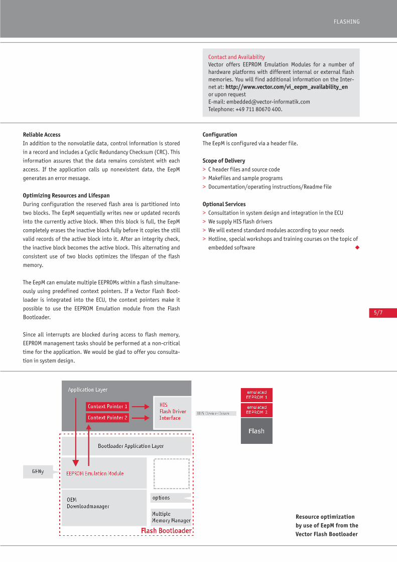
5/7
FLASHING
Reliable AccessIn addition to the nonvolatile data, control information is stored
in a record and includes a Cyclic Redundancy Checksum (CRC). This
information assures that the data remains consistent with each
access. If the application calls up nonexistent data, the EepM
generates an error message.
Optimizing Resources and Lifespan During configuration the reserved flash area is partitioned into
two blocks. The EepM sequentially writes new or updated records
into the currently active block. When this block is full, the EepM
completely erases the inactive block fully before it copies the still
valid records of the active block into it. After an integrity check,
the inactive block becomes the active block. This alternating and
consistent use of two blocks optimizes the lifespan of the flash
memory.
The EepM can emulate multiple EEPROMs within a flash simultane-
ously using predefined context pointers. If a Vector Flash Boot-
loader is integrated into the ECU, the context pointers make it
possible to use the EEPROM Emulation module from the Flash
Bootloader.
Since all interrupts are blocked during access to flash memory,
EEPROM management tasks should be performed at a non-critical
time for the application. We would be glad to offer you consulta-
tion in system design.
ConfigurationThe EepM is configured via a header file.
Scope of Delivery> C header files and source code
> Makefiles and sample programs
> Documentation/operating instructions/Readme file
Optional Services> Consultation in system design and integration in the ECU
> We supply HIS flash drivers
> We will extend standard modules according to your needs
> Hotline, special workshops and training courses on the topic of
embedded software ◆
Contact and AvailabilityVector offers EEPROM Emulation Modules for a number ofhardware platforms with different internal or external flashmemories. You will find additional information on the Inter-net at: http://www.vector.com/vi_eepm_availability_enor upon request E-mail: [email protected]: +49 711 80670 400.
Resource optimizationby use of EepM from theVector Flash Bootloader
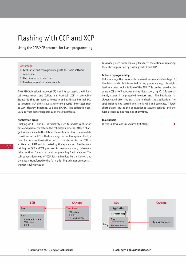
5/8
Flashing with CCP and XCPUsing the CCP/XCP protocol for flash programming
The CAN Calibration Protocol (CCP) – and its successor, the Univer-
sal Measurement and Calibration Protocol (XCP) – are ASAM
Standards that are used to measure and calibrate internal ECU
parameters. XCP offers several different physical interfaces such
as CAN, FlexRay, Ethernet, USB and SPI/SCI. The calibration tool
CANape from Vector supports all of these interfaces.
Application areasFlashing via CCP and XCP is primarily used to update calibration
data and parameter data in the calibration process. After a chan-
ge has been made to the data in the calibration tool, the new data
is written to the ECU’s flash memory via the bus system. First, a
flash kernel (see illustration, left) is transferred to the ECU, is
written into RAM and is started by the application. Besides con-
taining the CCP and XCP protocols for communication, it also con-
tains routines for erasing and programming flash memory. The
subsequent download of ECU data is handled by the kernel, and
the data is transferred to the flash chip. This achieves an especial-
ly space-saving solution.
Less widely used but technically feasible is the option of replacing
the entire application by flashing via CCP and XCP.
Failsafe reprogrammingUnfortunately, the use of a flash kernel has one disadvantage: If
the data transfer is interrupted during programming, this might
lead to a catastrophic failure of the ECU. This can be remedied by
using a CCP or XCP bootloader (see illustration, right). It is perma-
nently stored in a protected memory area. The bootloader is
always called after the start, and it checks the application. The
application is not started unless it is valid and complete. A flash
abort always causes the bootloader to assume control, and the
flash process can be resumed at any time.
Tool supportThe flash download is executed by CANape. ◆
Advantages
> Calibration and reprogramming with the same software
component
> Use CANape as a flash tool
> Reset-safe solutions are available
Flashing via an XCP bootloaderFlashing via XCP using a flash kernel

5/9
FLASHING
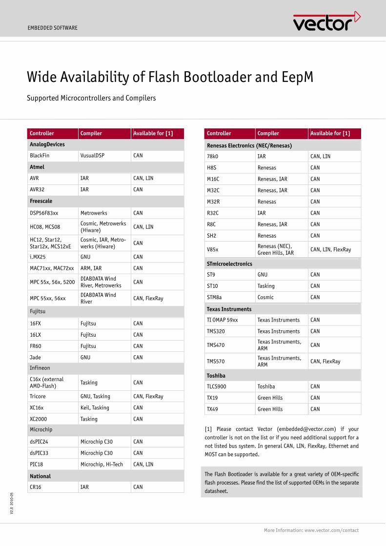
EMBEDDED SOFTWARE
More Information: www.vector.com/contact
V2.0
201
0-05
Controller Compiler Available for [1]
AnalogDevices
BlackFin VusualDSP CAN
Atmel
AVR IAR CAN, LIN
AVR32 IAR CAN
Freescale
DSP56F83xx Metrowerks CAN
HC08, MCS08 Cosmic, Metrowerks (Hiware) CAN, LIN
HC12, Star12, Star12x, MCS12xE
Cosmic, IAR, Metro-werks (Hiware) CAN
i.MX25 GNU CAN
MAC71xx, MAC72xx ARM, IAR CAN
MPC 55x, 56x, 5200 DIABDATA Wind River, Metrowerks CAN
MPC 55xx, 56xx DIABDATA Wind River CAN, FlexRay
Fujitsu
16FX Fujitsu CAN
16LX Fujitsu CAN
FR60 Fujitsu CAN
Jade GNU CAN
Infineon
C16x (external AMD-Flash) Tasking CAN
Tricore GNU, Tasking CAN, FlexRay
XC16x Keil, Tasking CAN
XC2000 Tasking CAN
Microchip
dsPIC24 Microchip C30 CAN
dsPIC33 Microchip C30 CAN
PIC18 Microchip, Hi-Tech CAN, LIN
National
CR16 IAR CAN
Controller Compiler Available for [1]
Renesas Electronics (NEC/Renesas)
78k0 IAR CAN, LIN
H8S Renesas CAN
M16C Renesas, IAR CAN
M32C Renesas, IAR CAN
M32R Renesas CAN
R32C IAR CAN
R8C Renesas, IAR CAN
SH2 Renesas CAN
V85x Renesas (NEC), Green Hills, IAR CAN, LIN, FlexRay
STmicroelectronics
ST9 GNU CAN
ST10 Tasking CAN
STM8a Cosmic CAN
Texas Instruments
TI OMAP 59xx Texas Instruments CAN
TMS320 Texas Instruments CAN
TMS470 Texas Instruments, ARM CAN
TMS570 Texas Instruments, ARM CAN, FlexRay
Toshiba
TLCS900 Toshiba CAN
TX19 Green Hills CAN
TX49 Green Hills CAN
[1] Please contact Vector ([email protected]) if your
controller is not on the list or if you need additional support for a
not listed bus system. In general CAN, LIN, FlexRay, Ethernet and
MOST can be supported.
The Flash Bootloader is available for a great variety of OEM-specific
flash processes. Please find the list of supported OEMs in the separate
datasheet.
Wide Availability of Flash Bootloader and EepM Supported Microcontrollers and Compilers

EMBEDDED SOFTWARE
More Information: www.vector.com/contact
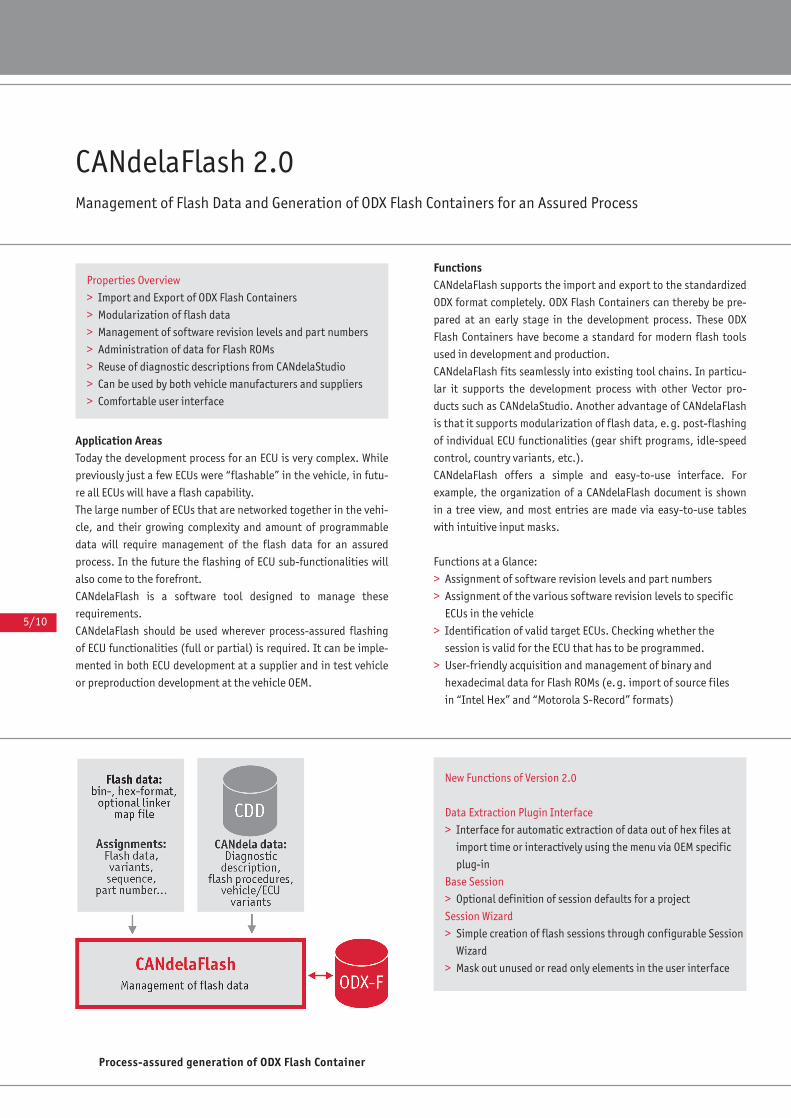
5/10
Application AreasToday the development process for an ECU is very complex. While
previously just a few ECUs were “flashable” in the vehicle, in futu-
re all ECUs will have a flash capability.
The large number of ECUs that are networked together in the vehi-
cle, and their growing complexity and amount of programmable
data will require management of the flash data for an assured
process. In the future the flashing of ECU sub-functionalities will
also come to the forefront.
CANdelaFlash is a software tool designed to manage these
requirements.
CANdelaFlash should be used wherever process-assured flashing
of ECU functionalities (full or partial) is required. It can be imple-
mented in both ECU development at a supplier and in test vehicle
or preproduction development at the vehicle OEM.
FunctionsCANdelaFlash supports the import and export to the standardized
ODX format completely. ODX Flash Containers can thereby be pre-
pared at an early stage in the development process. These ODX
Flash Containers have become a standard for modern flash tools
used in development and production.
CANdelaFlash fits seamlessly into existing tool chains. In particu-
lar it supports the development process with other Vector pro-
ducts such as CANdelaStudio. Another advantage of CANdelaFlash
is that it supports modularization of flash data, e.g. post-flashing
of individual ECU functionalities (gear shift programs, idle-speed
control, country variants, etc.).
CANdelaFlash offers a simple and easy-to-use interface. For
example, the organization of a CANdelaFlash document is shown
in a tree view, and most entries are made via easy-to-use tables
with intuitive input masks.
Functions at a Glance:
> Assignment of software revision levels and part numbers
> Assignment of the various software revision levels to specific
ECUs in the vehicle
> Identification of valid target ECUs. Checking whether the
session is valid for the ECU that has to be programmed.
> User-friendly acquisition and management of binary and
hexadecimal data for Flash ROMs (e.g. import of source files
in “Intel Hex” and “Motorola S-Record” formats)
Process-assured generation of ODX Flash Container
CANdelaFlash 2.0Management of Flash Data and Generation of ODX Flash Containers for an Assured Process
Properties Overview
> Import and Export of ODX Flash Containers
> Modularization of flash data
> Management of software revision levels and part numbers
> Administration of data for Flash ROMs
> Reuse of diagnostic descriptions from CANdelaStudio
> Can be used by both vehicle manufacturers and suppliers
> Comfortable user interface
New Functions of Version 2.0
Data Extraction Plugin Interface
> Interface for automatic extraction of data out of hex files at
import time or interactively using the menu via OEM specific
plug-in
Base Session
> Optional definition of session defaults for a project
Session Wizard
> Simple creation of flash sessions through configurable Session
Wizard
> Mask out unused or read only elements in the user interface
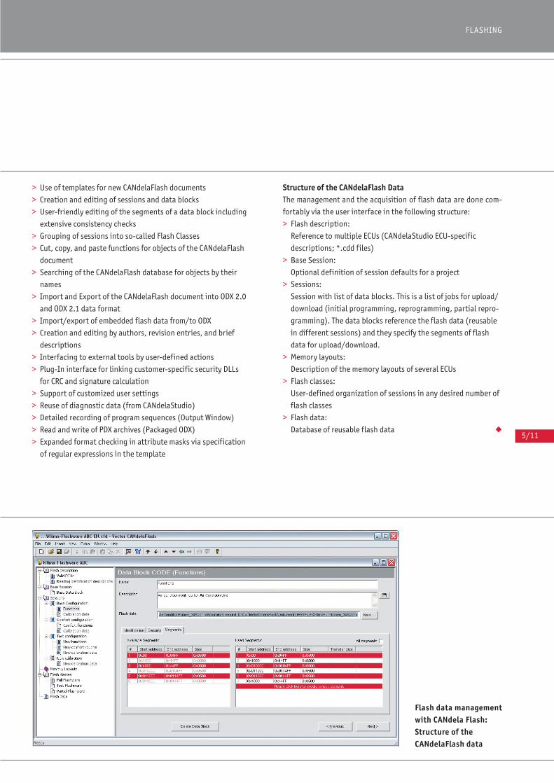
5/11
FLASHING
> Use of templates for new CANdelaFlash documents
> Creation and editing of sessions and data blocks
> User-friendly editing of the segments of a data block including
extensive consistency checks
> Grouping of sessions into so-called Flash Classes
> Cut, copy, and paste functions for objects of the CANdelaFlash
document
> Searching of the CANdelaFlash database for objects by their
names
> Import and Export of the CANdelaFlash document into ODX 2.0
and ODX 2.1 data format
> Import/export of embedded flash data from/to ODX
> Creation and editing by authors, revision entries, and brief
descriptions
> Interfacing to external tools by user-defined actions
> Plug-In interface for linking customer-specific security DLLs
for CRC and signature calculation
> Support of customized user settings
> Reuse of diagnostic data (from CANdelaStudio)
> Detailed recording of program sequences (Output Window)
> Read and write of PDX archives (Packaged ODX)
> Expanded format checking in attribute masks via specification
of regular expressions in the template
Structure of the CANdelaFlash DataThe management and the acquisition of flash data are done com-
fortably via the user interface in the following structure:
> Flash description:
Reference to multiple ECUs (CANdelaStudio ECU-specific
descriptions; *.cdd files)
> Base Session:
Optional definition of session defaults for a project
> Sessions:
Session with list of data blocks. This is a list of jobs for upload/
download (initial programming, reprogramming, partial repro-
gramming). The data blocks reference the flash data (reusable
in different sessions) and they specify the segments of flash
data for upload/download.
> Memory layouts:
Description of the memory layouts of several ECUs
> Flash classes:
User-defined organization of sessions in any desired number of
flash classes
> Flash data:
Database of reusable flash data ◆
Flash data managementwith CANdela Flash:Structure of the CANdelaFlash data
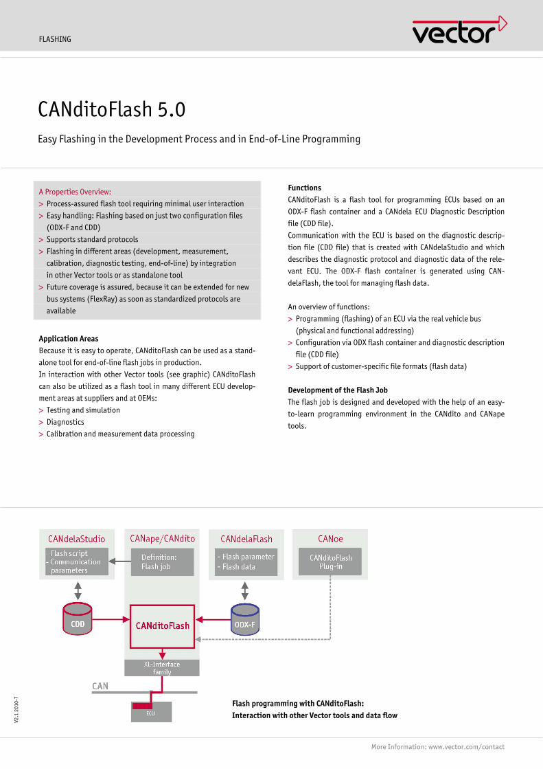
FLASHING
More Information: www.vector.com/contact
A Properties Overview:
> Process-assured flash tool requiring minimal user interaction
> Easy handling: Flashing based on just two configuration files
(ODX-F and CDD)
> Supports standard protocols
> Flashing in different areas (development, measurement,
calibration, diagnostic testing, end-of-line) by integration
in other Vector tools or as standalone tool
> Future coverage is assured, because it can be extended for new
bus systems (FlexRay) as soon as standardized protocols are
available
Application Areas Because it is easy to operate, CANditoFlash can be used as a stand-
alone tool for end-of-line flash jobs in production.
In interaction with other Vector tools (see graphic) CANditoFlash
can also be utilized as a flash tool in many different ECU develop-
ment areas at suppliers and at OEMs:
> Testing and simulation
> Diagnostics
> Calibration and measurement data processing
Functions CANditoFlash is a flash tool for programming ECUs based on an
ODX-F flash container and a CANdela ECU Diagnostic Description
file (CDD file).
Communication with the ECU is based on the diagnostic descrip-
tion file (CDD file) that is created with CANdelaStudio and which
describes the diagnostic protocol and diagnostic data of the rele-
vant ECU. The ODX-F flash container is generated using CAN-
delaFlash, the tool for managing flash data.
An overview of functions:
> Programming (flashing) of an ECU via the real vehicle bus
(physical and functional addressing)
> Configuration via ODX flash container and diagnostic description
file (CDD file)
> Support of customer-specific file formats (flash data)
Development of the Flash Job The flash job is designed and developed with the help of an easy-
to-learn programming environment in the CANdito and CANape
tools.
CANditoFlash 5.0 Easy Flashing in the Development Process and in End-of-Line Programming
V2.1
201
0-7
Flash programming with CANditoFlash: Interaction with other Vector tools and data flow

FLASHING
More Information: www.vector.com/contact
The following functions are provided in flash job programming in
CANape/CANdito:
> OEM-specific flash job: Simple, problem-oriented library func-
tions for instancing and parameterizing diagnostic functions
> Easy access to flash parameters
> Convenient import of flash data
> Library is expandable (e.g. for import of customer-specific data)
The flash job (flash script) is transferred to the Diagnostic Descrip-
tion file (CDD file) with CANdelaStudio.
If necessary, Vector can develop the flash job as a contract service.
Supported Protocols > ISO 15765 Diagnostics on CAN
> ISO 14229 Unified Diagnostic Services on CAN (UDS)
Interaction and Interfaces CANditoFlash can be run:
> As a standalone tool, e.g. for end-of-line flashing
> As part of CANape (effective with version 6.5 SP1) or CANdito
(effective with version 2.5 SP1)
> In CANoe as a plug-in. A precondition is a standalone installa-
tion of CANditoFlash or an installed license for CANape/CANdito
version 6.5/2.5 SP1 or higher.
System Requirements > Windows XP, Vista (32-bit version) or Windows 7 (32- and 64-bit
version)
> Vector CAN hardware interfaces
Configuration dialog: Flashing based on ODX-F data
6/0
VectorAcademy
Seminar or Workshop?Vector offers seminars and workshops on Vector software tools as
well as the latest bus technologies and protocols at Vector Group
locations worldwide.
VectorAcademy seminars serve to communicate theoretical basics,
while workshops distinguish themselves through their applicability,
practical examples, and exercises.
ModularityTrainings are partly constructed of several independent, one-day
modules designed to follow one another. Beginners and advanced
users can adjust their individual training program to suit their own
needs.
Customer-Specific TrainingsAdditionally, we offer customized training courses, where we com-
bine or expand the contents according to your needs. If desired we
can also conduct all training courses at your company site. We would
be glad to provide you with a quotation based on your specific needs.
Please contact our training consultants:
Vector Informatik: [email protected]
Vector Consulting Services: [email protected]
Vector CANtech: [email protected]
Vector Scandinavia: [email protected]
Vector France: [email protected]
Vector Japan: [email protected]
Vector Great Britain: [email protected]
Vector Korea: [email protected]
The Training TeamOur training team consists of experienced engineers, who enjoy
sharing their experience and knowledge base.
A continuous flow of information between trainers and development
departments ensures that the training courses we offer reflect cur-
rent trends and developments.
PremisesWe conduct our trainings in generously appointed and modern class-
rooms, equipped with state-of-the-art training technology and
powerful workstations, running the latest development, analysis,
measurement, and diagnostics software. Excercise hardware and
demonstration objects complete the working environment.
You will find the latest information on current dates, additions
to the training offerings, and information about registration of
the Vector Group at www.vector-academy.com.

4/2
Germany
Katalog E Diagnose '10 02.02.2010 10:39 Uhr Seite 4/2
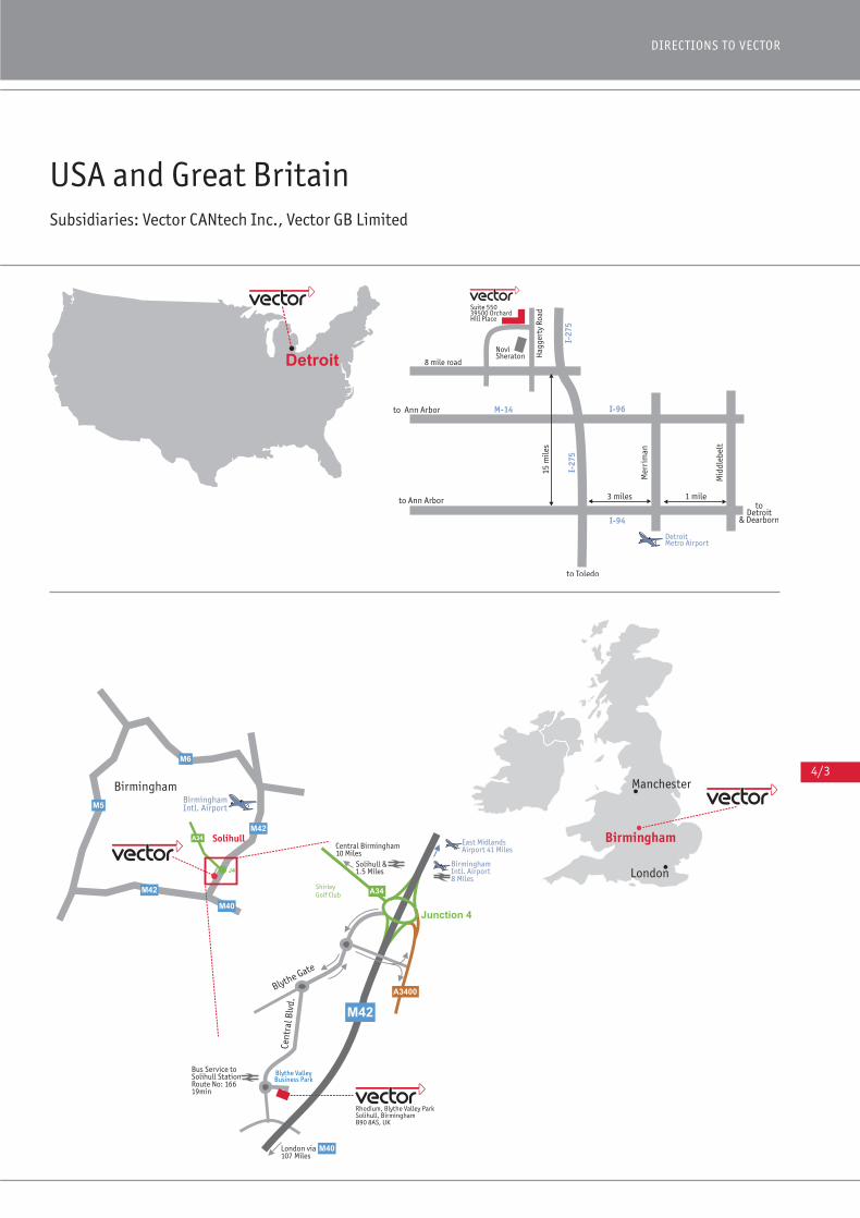
4/3
DIRECTIONS TO VECTOR
USA and Great BritainSubsidiaries: Vector CANtech Inc., Vector GB Limited
Vector Katalog Diagnose EN 04.02.2010 13:16 Uhr Seite 4/3
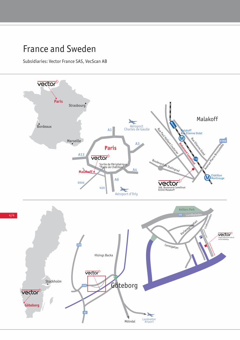
4/4
France and SwedenSubsidiaries: Vector France SAS, VecScan AB
Katalog E Diagnose '10 02.02.2010 10:39 Uhr Seite 4/4
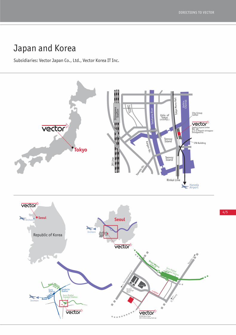
4/5
DIRECTIONS TO VECTOR
Japan and KoreaSubsidiaries: Vector Japan Co., Ltd., Vector Korea IT Inc.
Katalog E Diagnose '10 02.02.2010 10:40 Uhr Seite 4/5
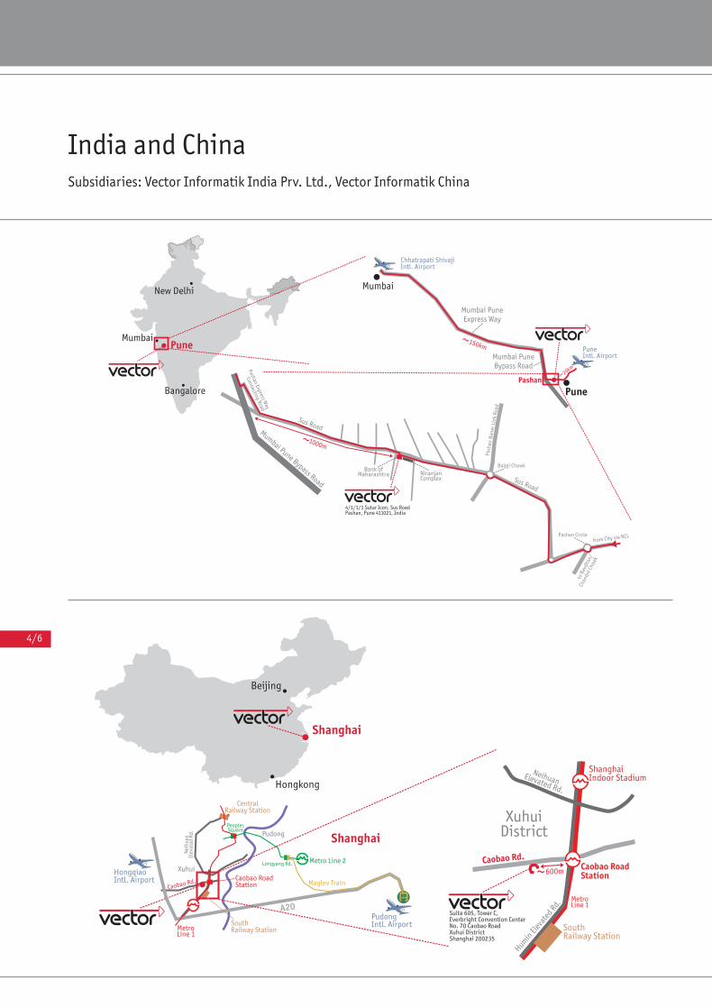
4/6
India and ChinaSubsidiaries: Vector Informatik India Prv. Ltd., Vector Informatik China
Katalog E Diagnose '10 02.02.2010 10:40 Uhr Seite 4/6

Your Contact
www.vector.com V
Germany and all countries not named below
Vector Informatik GmbHVector Consulting Services GmbH Ingersheimer Str. 24 70499 Stuttgart GERMANY Tel.: +49 711 80670-0 Fax: +49 711 80670-111
France, Belgium, Luxembourg
Vector France 168, Boulevard Camélinat 92240 Malakoff FRANCE Tel.: +33 1 4231 4000 Fax: +33 1 4231 4009
Sweden, Denmark, Norway, Finland, Iceland
VecScan AB Theres Svenssons Gata 9 41755 Göteborg SWEDEN Tel.: +46 31 764 7600 Fax: +46 31 764 7619
United Kingdom & Ireland
Vector GB Limited Rhodium, Central BoulevardBlythe Valley ParkSolihull, BirminghamWest Midlands, B90 8ASUNITED KINGDOM Tel.: +44 121 50681-50Fax: +44 121 50681-69
China
Vector Informatik GmbH Shanghai Representative Office Suite 605, Tower C, Everbright Convention CenterNo. 70 Caobao Road, Xuhui DistrictShanghai 200235P.R. CHINATel.: +86 21 6432 53530Fax: +86 21 6432 5308
USA, Canada, Mexico
Vector CANtech, Inc. Suite 550 39500 Orchard Hill Place Novi, MI 48375 USA Tel.: +1 248 449 9290 Fax: +1 248 449 9704
Japan
Vector Japan Co., Ltd. Seafort Square Center Bld. 18F 2-3-12 Higashi-shinagawa, Shinagawa-ku Tokyo 140-0002 JAPAN Tel.: +81 3 5769 7800 Fax: +81 3 5769 6975
Korea
Vector Korea IT Inc. 1406 Mario Tower 222-12 Guro-dong, Guro-guSeoul 152-848REP. OF SOUTH KOREA Tel.: +82 2 8070 600Fax: +82 2 8070 601
India
Vector Informatik India Prv. Ltd.4/1/1/1, 3rd floor, Sutar IconSus RoadPashanPune 411021INDIATel.: +91 20 2587 2023Fax: +91 20 2587 2025
Get Price Quote


![1.2 New ECU diagnosis software with 2009/4 - Shrani.si · 1.2 New ECU diagnosis software with 2009/4 ... Mercedes Benz CLC-class [203] ... SBC (Sensotronic Brake Control) 3](https://img.pdfslide.us/doc/110x75/5b15b0b27f8b9a06298dc414/12-new-ecu-diagnosis-software-with-20094-12-new-ecu-diagnosis-software.jpg)