Embed Size (px)
Citation preview
1
M3DK MEMS plug compatible ECU
Operating manual

2
Software installation The M3DK Windows mapping software is written in 32-bit code, which means it needs to be operated through MS Windows 95 or later. The software files are supplied compressed in a single installation file on a 3-½ floppy disk. They must be uncompressed and installed onto your PC before use. Due to the size of the program, it cannot be operated from the floppy disk and will have to be installed on to the hard drive of your PC. To install the mapping control software insert the disk in to drive A. From the ‘Start’ menu, select RUN. When asked for a filename, type a:\setup.exe, press <enter> Alternatively use Windows Explorer to browse to drive A, then open the file named ‘setup.exe’. Follow the on screen instructions. Before the files are installed, you will be asked for a location for these files. The default location is C:\Program Files\M3DK. Select the Next button to continue or enter another location of your choosing. When the files have been successfully installed click the finish button to return to windows. A shortcut icon will be placed on the desktop and also in the Programs/Emerald directory accessed through the Start menu. Use either of these icons to start the M3DK software. Before the M3DK software starts, you will be asked which serial communications port you are using to connect to the ECU. Com-Port 1 is the most common choice but if this is used for a mouse use Com-Port 2. The M3DK software will automatically highlight the first unused Com-Port.

3
Getting up and running Before M3DK ECU can be used, it has to be calibrated to the throttle pot fitted to your engine. Once these settings are known, the ECU can correctly relate the throttle pot input to the ignition/injection maps. If a stepper motor idle control valve fit and is to be used it will need to be reset to it’s fully shut position. If fitted, first unplug the standard MEMs ECU and connect the loom plug to the M3DK. The original ECU can be left in place or completely removed. Install the M3DK ECU and connect to the standard loom plug. Insert the 9-pin DIN plug on the Comms lead into the ECU (the socket is found on the rear of the ECU). Insert the green 9-pin D-type socket of the Comms lead to either Com-Port 1 or 2 of your PC. Execute the software as instructed in the previous section. Throttle pot set-up Switch the ignition key on. The led on the rear of the ECU should light RED to indicate that it is powered & operating. The status box on the bottom right hand corner of the M3DK software screen should display ‘Status – ECU connected’ to show that a communications link has been established. From the ‘Setup’ menu at the top of the M3DK screen, select ‘Throttle pot’. Follow the on screen instructions. You will be asked to apply full throttle and release. The software will capture the throttle pot readings and use these to calibrate the ECU. Idle Air Control Valve stepper motor set-up Skip this section if you do not have a stepper motor type IACV (identified by a 4 or 5 pin connector on the valve itself). Although an IACV using a stepper motor provides accurate air bypass metering there is no position information feedback for the ECU. The only way for the ECU know the current IACV position is to keep a track of how much the ECU has moved it with reference to the fully shut position. Therefore you need to ensure the IACV is fully shut for the first time installation so that the ECU and motor are in sync’. Assuming the map you have downloaded to the ECU has settings for IACV control, and your engine is fitted with a stepper motor IACV, you will need to reset the
4
stepper motor to it’s fully home position before starting the engine. Resetting the stepper motor can be achieved in two ways. With the IACV motor control mode set to ‘Fixed – manual control’ (found in the Idle control screen, F5) the motor can be reset by pressing the Home key on the keyboard from the ‘Live Adjustments’ screen. You should notice that the IACV pos value changes to 120 and after a second or so returns to 0. At the same time you may hear the IACV motor whirring. Before starting the engine you may need to open the IACV a little (using the shift/page up keys from the ‘Live Adjustments’ screen) to allow enough air by-pass to enable the engine to maintain idle speed. Start with an initial position of 40 and work from there once the engine is running. With the IACV motor control mode set to ‘Mapped position’ only the ECU has control of the IACV stepper motor position, the IACV control keys from the ‘Live Adjustments’ screen have no effect. In this mode the IACV is over-motored into the fully shut position each time the ignition is switched off. In normal use this is sufficient to ensure the motor is fully shut, but for first time installation the original stepper motor position is not known – it is possible it could be fully open. To make sure the motor is fully shut, switch the ignition off (you may hear the IACV whirring momentarily) for a few seconds and then switch the ignition back on then wait for the fuel pump to finish priming. Repeat this process a few times to be sure that the motor is definitely shut. Finally Switch the ignition off, the ECU will then be reset with the new settings next time it is powered up. Follow the instructions in the ‘first time installation’ section of the ‘Rover K-series immobiliser (if fitted/used) chapter at the end of this manual. The engine is now ready to start with the supplied base map. Note: the led on the rear of the ECU will turn from RED to GREEN to indicate that the ECU has recognised engine rotation. If the ECU is immobilised, the led will remain RED
5
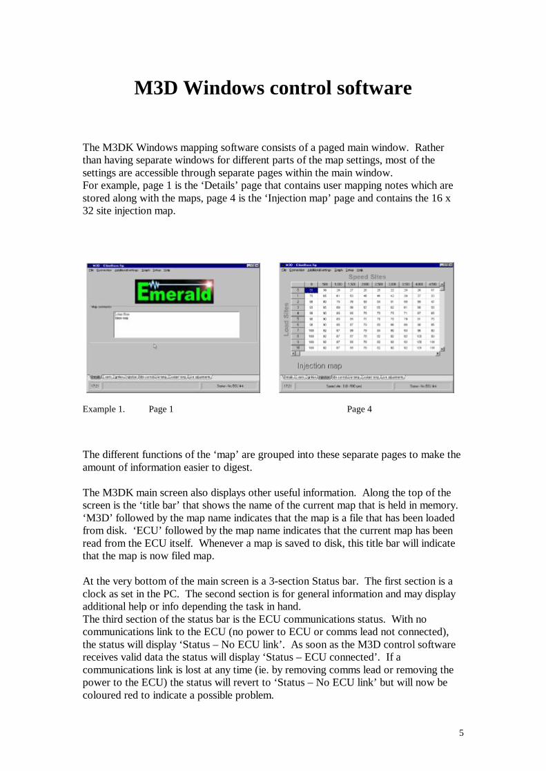
M3D Windows control software The M3DK Windows mapping software consists of a paged main window. Rather than having separate windows for different parts of the map settings, most of the settings are accessible through separate pages within the main window. For example, page 1 is the ‘Details’ page that contains user mapping notes which are stored along with the maps, page 4 is the ‘Injection map’ page and contains the 16 x 32 site injection map.
Example 1. Page 1 Page 4 The different functions of the ‘map’ are grouped into these separate pages to make the amount of information easier to digest. The M3DK main screen also displays other useful information. Along the top of the screen is the ‘title bar’ that shows the name of the current map that is held in memory. ‘M3D’ followed by the map name indicates that the map is a file that has been loaded from disk. ‘ECU’ followed by the map name indicates that the current map has been read from the ECU itself. Whenever a map is saved to disk, this title bar will indicate that the map is now filed map. At the very bottom of the main screen is a 3-section Status bar. The first section is a clock as set in the PC. The second section is for general information and may display additional help or info depending the task in hand. The third section of the status bar is the ECU communications status. With no communications link to the ECU (no power to ECU or comms lead not connected), the status will display ‘Status – No ECU link’. As soon as the M3D control software receives valid data the status will display ‘Status – ECU connected’. If a communications link is lost at any time (ie. by removing comms lead or removing the power to the ECU) the status will revert to ‘Status – No ECU link’ but will now be coloured red to indicate a possible problem.
6
Navigating your way around the software As with most Windows software, the mouse pointer is primary input device but this is not always convenient especially when operating from a laptop. If it is either impractical or just too slow to use the mouse pointer the keyboard can be used instead. The M3D software can be operated entirely from the keyboard with key shortcuts for many functions. To navigate around the various settings within a page, using a keyboard, repeatedly press the TAB key until the cursor is at the required setting. If there is only one possible map setting within any particular page or screen, this input is active automatically. Selecting with the mouse pointer or cursor activates a particular map setting. Various methods are used to change the value of an activated map setting. These methods will depend on the type of setting you are trying to change.
The map pages The pages available are shown as ‘Tabs’ near the bottom of the main screen. Note other software versions may have different tabs to those shown in the example below. To move to another page simply click the desired tab with the mouse pointer. As an alternative to using the mouse, you can use the shortcut keys: -
Example 2. Page tabs
Keyboard shortcuts for Page tabs F1…Details screen F2…Events screen (various rpm & temperature activated events) F3…Ignition map F4…Injection map F5…Idle control settings F6…Air temperature correction settings F7…Coolant temperature correction settings F8…Live adjustments
7
Each screen contains various data settings that can be changed by activating with the mouse and/or keyboard. The mouse is not specifically required; any task can be accomplished from the keyboard. TAB…Moves the cursor to the next available data entry control on screen (pressing
TAB repeatedly, will cycle the cursor around all the controls)
The Menu Pressing the ALT key activates the menu. Pressing the ALT key again returns the cursor control to the main M3D window. Once active, the menu can be navigated by using the cursor keys. Move the highlight until it is on the desired function and press ENTER to select it. Using the mouse is just a case of clicking on the desired menu heading and then on the desired function in the drop down menu. Menu headings File Open map file Save map file Exit Connection Read ECU Program ECU Additional settings Accel Fuelling Injection Scaling RPM Correction for Coolant Enrichment Battery Voltage Compensation Lambda Control Idle Air Control Air Pressure Compensation Double Injector Control Graph Plot Graph Setup Throttle Pot Distributer / Pickup Immobiliser ECU Configuration Map Sensor Oxygen Sensor Temperature Sensors Help Contents About Diag data Diagnostics
8
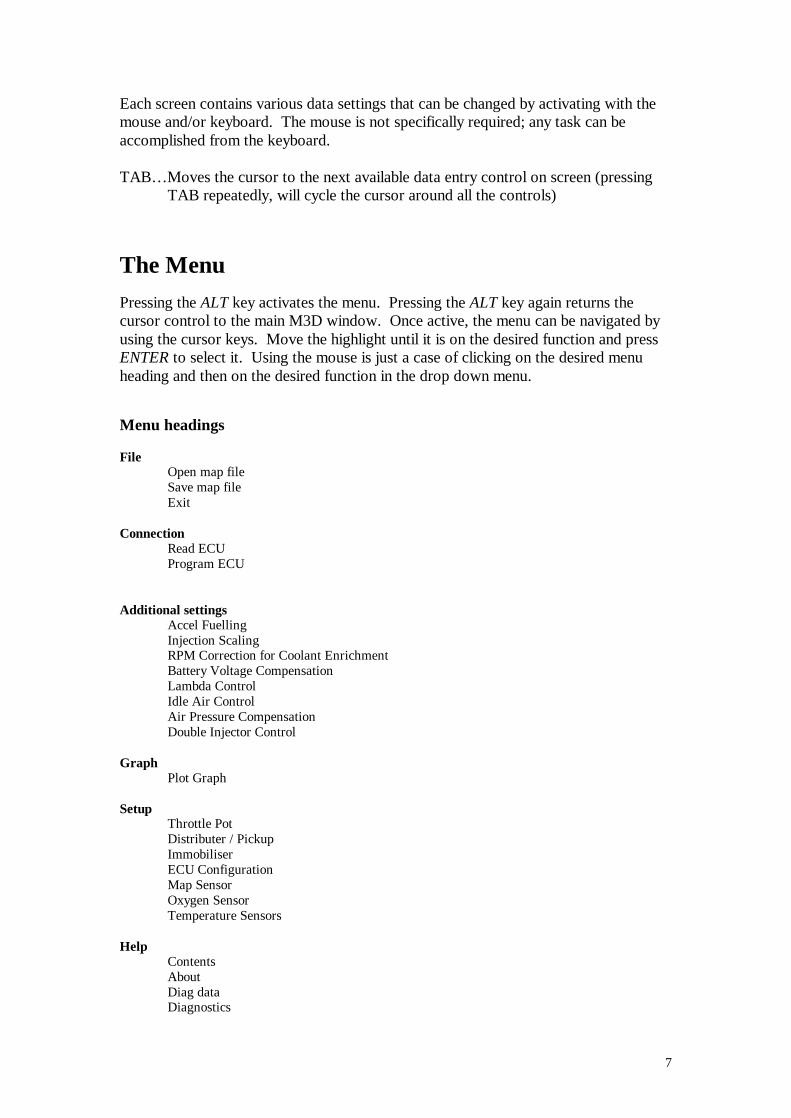
Map pages The eight pages of the main M3D window contain the bulk of the map settings, additional settings & functions are also available through the menu at the top of the screen. Details (F1) When first loaded, the M3DK software will default to this page. Details or comments that are attached to the map currently loaded into memory will be shown in the ‘Map comments’ text box.
The map comments text box can hold up to 255 characters. Once the limit is reached you will not be able to enter any more text. Note that ‘spaces’ after any text also count. If you find that you are not able to enter as much info’ as you would like, check that there are no spaces following your text.
9
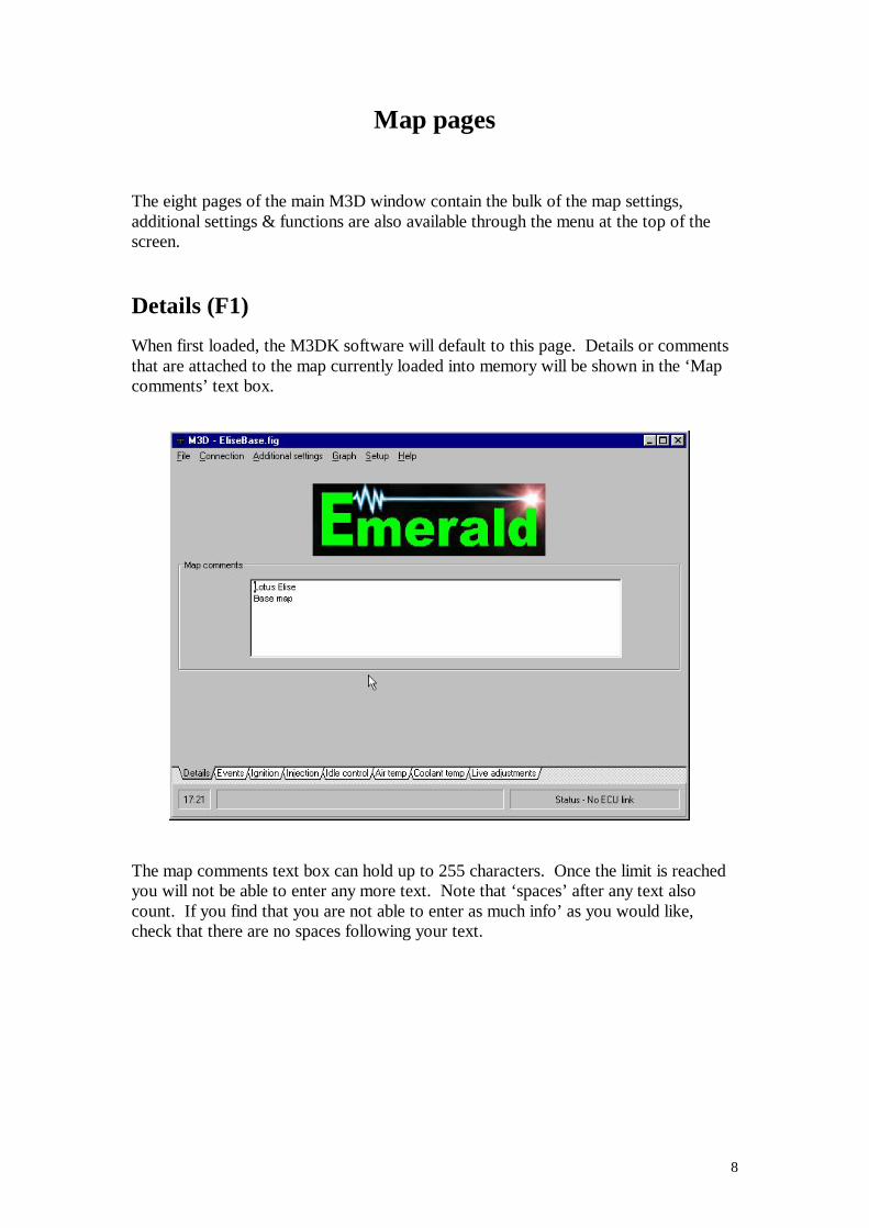
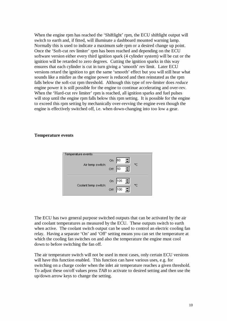
Events (F2) This page contains a number of settings that dictate the ECU’s response to certain input conditions. These settings are laid out in four areas, RPM events, Overrun cut-off, Battery Voltage and Temperature events.
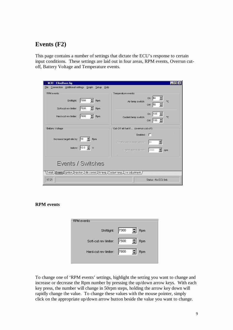
RPM events
To change one of ‘RPM events’ settings, highlight the setting you want to change and increase or decrease the Rpm number by pressing the up/down arrow keys. With each key press, the number will change in 50rpm steps, holding the arrow key down will rapidly change the value. To change these values with the mouse pointer, simply click on the appropriate up/down arrow button beside the value you want to change.
10
When the engine rpm has reached the ‘Shiftlight’ rpm, the ECU shiftlight output will switch to earth and, if fitted, will illuminate a dashboard mounted warning lamp. Normally this is used to indicate a maximum safe rpm or a desired change up point. Once the ‘Soft-cut rev limiter’ rpm has been reached and depending on the ECU software version either every third ignition spark (4 cylinder system) will be cut or the ignition will be retarded to zero degrees. Cutting the ignition sparks in this way ensures that each cylinder is cut in turn giving a ‘smooth’ rev limit. Later ECU versions retard the ignition to get the same ‘smooth’ effect but you will still hear what sounds like a misfire as the engine power is reduced and then reinstated as the rpm falls below the soft-cut rpm threshold. Although this type of rev-limiter does reduce engine power it is still possible for the engine to continue accelerating and over-rev. When the ‘Hard-cut rev limiter’ rpm is reached, all ignition sparks and fuel pulses will stop until the engine rpm falls below this rpm setting. It is possible for the engine to exceed this rpm setting by mechanically over-revving the engine even though the engine is effectively switched off, i.e. when down-changing into too low a gear. Temperature events
The ECU has two general purpose switched outputs that can be activated by the air and coolant temperatures as measured by the ECU. These outputs switch to earth when active. The coolant switch output can be used to control an electric cooling fan relay. Having a separate ‘On’ and ‘Off’ setting means you can set the temperature at which the cooling fan switches on and also the temperature the engine must cool down to before switching the fan off. The air temperature switch will not be used in most cases, only certain ECU versions will have this function enabled. This function can have various uses, e.g. for switching on a charge cooler when the inlet air temperature reaches a given threshold. To adjust these on/off values press TAB to activate to desired setting and then use the up/down arrow keys to change the setting.
11
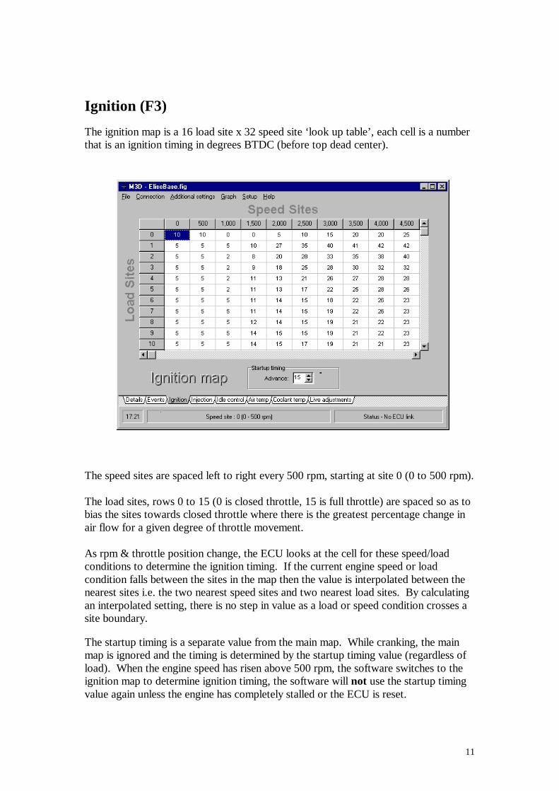
Ignition (F3) The ignition map is a 16 load site x 32 speed site ‘look up table’, each cell is a number that is an ignition timing in degrees BTDC (before top dead center).
The speed sites are spaced left to right every 500 rpm, starting at site 0 (0 to 500 rpm). The load sites, rows 0 to 15 (0 is closed throttle, 15 is full throttle) are spaced so as to bias the sites towards closed throttle where there is the greatest percentage change in air flow for a given degree of throttle movement. As rpm & throttle position change, the ECU looks at the cell for these speed/load conditions to determine the ignition timing. If the current engine speed or load condition falls between the sites in the map then the value is interpolated between the nearest sites i.e. the two nearest speed sites and two nearest load sites. By calculating an interpolated setting, there is no step in value as a load or speed condition crosses a site boundary. The startup timing is a separate value from the main map. While cranking, the main map is ignored and the timing is determined by the startup timing value (regardless of load). When the engine speed has risen above 500 rpm, the software switches to the ignition map to determine ignition timing, the software will not use the startup timing value again unless the engine has completely stalled or the ECU is reset.
12
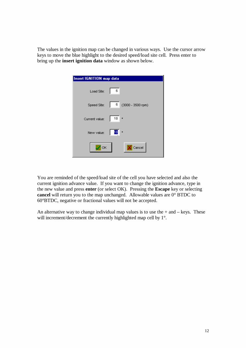
The values in the ignition map can be changed in various ways. Use the cursor arrow keys to move the blue highlight to the desired speed/load site cell. Press enter to bring up the insert ignition data window as shown below.
You are reminded of the speed/load site of the cell you have selected and also the current ignition advance value. If you want to change the ignition advance, type in the new value and press enter (or select OK). Pressing the Escape key or selecting cancel will return you to the map unchanged. Allowable values are 0° BTDC to 60°BTDC, negative or fractional values will not be accepted. An alternative way to change individual map values is to use the + and – keys. These will increment/decrement the currently highlighted map cell by 1°.
13
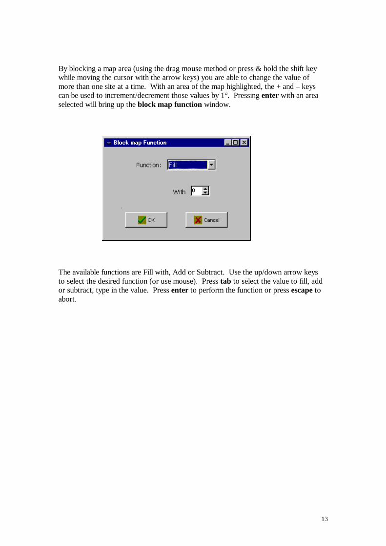
By blocking a map area (using the drag mouse method or press & hold the shift key while moving the cursor with the arrow keys) you are able to change the value of more than one site at a time. With an area of the map highlighted, the + and – keys can be used to increment/decrement those values by 1°. Pressing enter with an area selected will bring up the block map function window.
The available functions are Fill with, Add or Subtract. Use the up/down arrow keys to select the desired function (or use mouse). Press tab to select the value to fill, add or subtract, type in the value. Press enter to perform the function or press escape to abort.
14
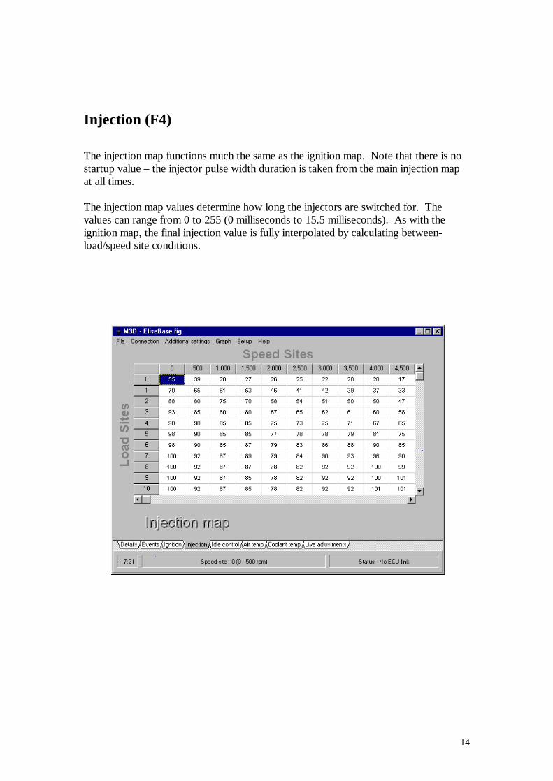
Injection (F4) The injection map functions much the same as the ignition map. Note that there is no startup value – the injector pulse width duration is taken from the main injection map at all times. The injection map values determine how long the injectors are switched for. The values can range from 0 to 255 (0 milliseconds to 15.5 milliseconds). As with the ignition map, the final injection value is fully interpolated by calculating between-load/speed site conditions.
15
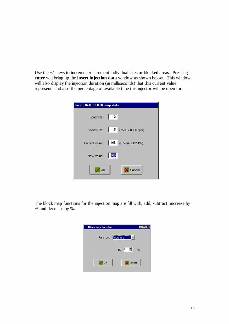
Use the +/- keys to increment/decrement individual sites or blocked areas. Pressing enter will bring up the insert injection data window as shown below. This window will also display the injection duration (in milliseconds) that this current value represents and also the percentage of available time this injector will be open for.
The block map functions for the injection map are fill with, add, subtract, increase by % and decrease by %.
16
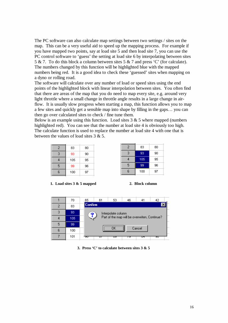
The PC software can also calculate map settings between two settings / sites on the map. This can be a very useful aid to speed up the mapping process. For example if you have mapped two points, say at load site 5 and then load site 7, you can use the PC control software to ‘guess’ the setting at load site 6 by interpolating between sites 5 & 7. To do this block a column between sites 5 & 7 and press ‘C’ (for calculate). The numbers changed by this function will be highlighted blue with the mapped numbers being red. It is a good idea to check these ‘guessed’ sites when mapping on a dyno or rolling road. The software will calculate over any number of load or speed sites using the end points of the highlighted block with linear interpolation between sites. You often find that there are areas of the map that you do need to map every site, e.g. around very light throttle where a small change in throttle angle results in a large change in air-flow. It is usually slow progress when starting a map, this function allows you to map a few sites and quickly get a sensible map into shape by filling in the gaps… you can then go over calculated sites to check / fine tune them. Below is an example using this function. Load sites 3 & 5 where mapped (numbers highlighted red). You can see that the number at load site 4 is obviously too high. The calculate function is used to replace the number at load site 4 with one that is between the values of load sites 3 & 5.
1. Load sites 3 & 5 mapped 2. Block column
3. Press ‘C’ to calculate between sites 3 & 5
17
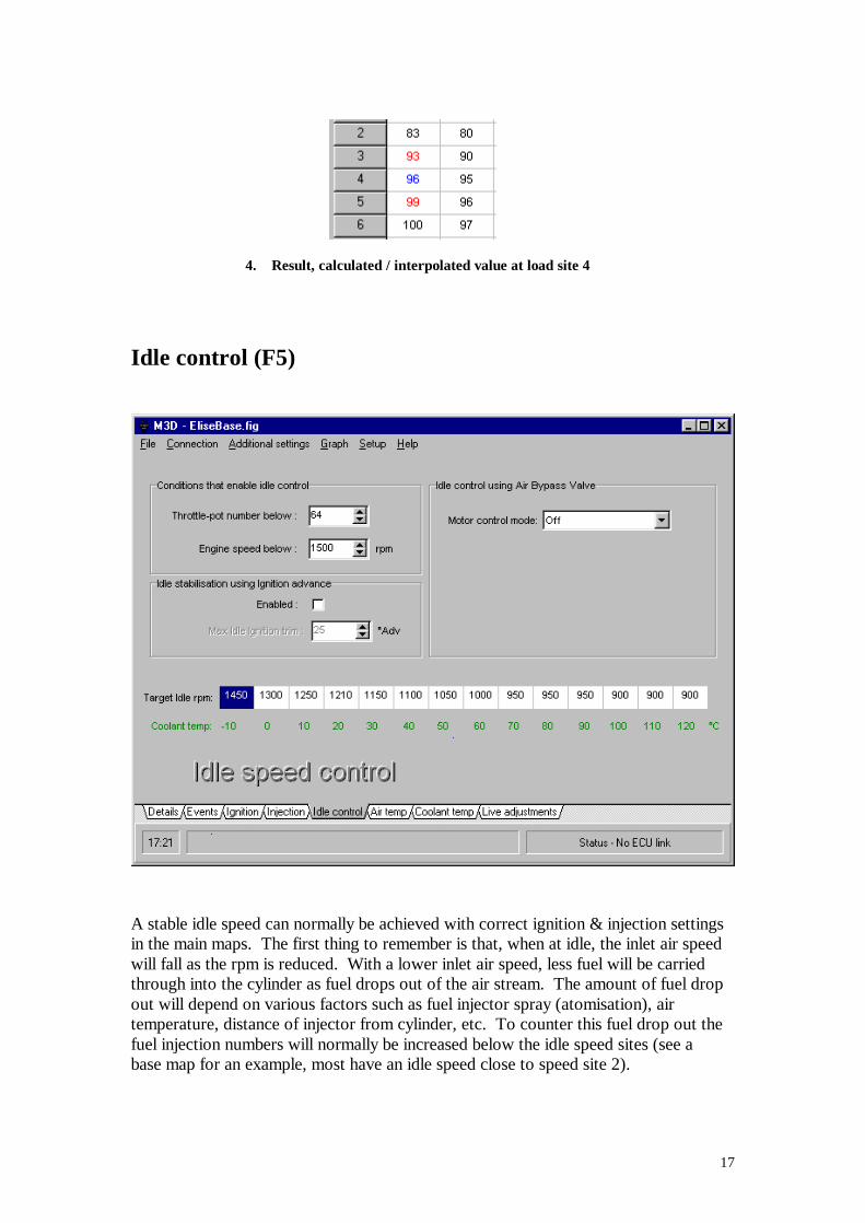
4. Result, calculated / interpolated value at load site 4
Idle control (F5)
A stable idle speed can normally be achieved with correct ignition & injection settings in the main maps. The first thing to remember is that, when at idle, the inlet air speed will fall as the rpm is reduced. With a lower inlet air speed, less fuel will be carried through into the cylinder as fuel drops out of the air stream. The amount of fuel drop out will depend on various factors such as fuel injector spray (atomisation), air temperature, distance of injector from cylinder, etc. To counter this fuel drop out the fuel injection numbers will normally be increased below the idle speed sites (see a base map for an example, most have an idle speed close to speed site 2).
18
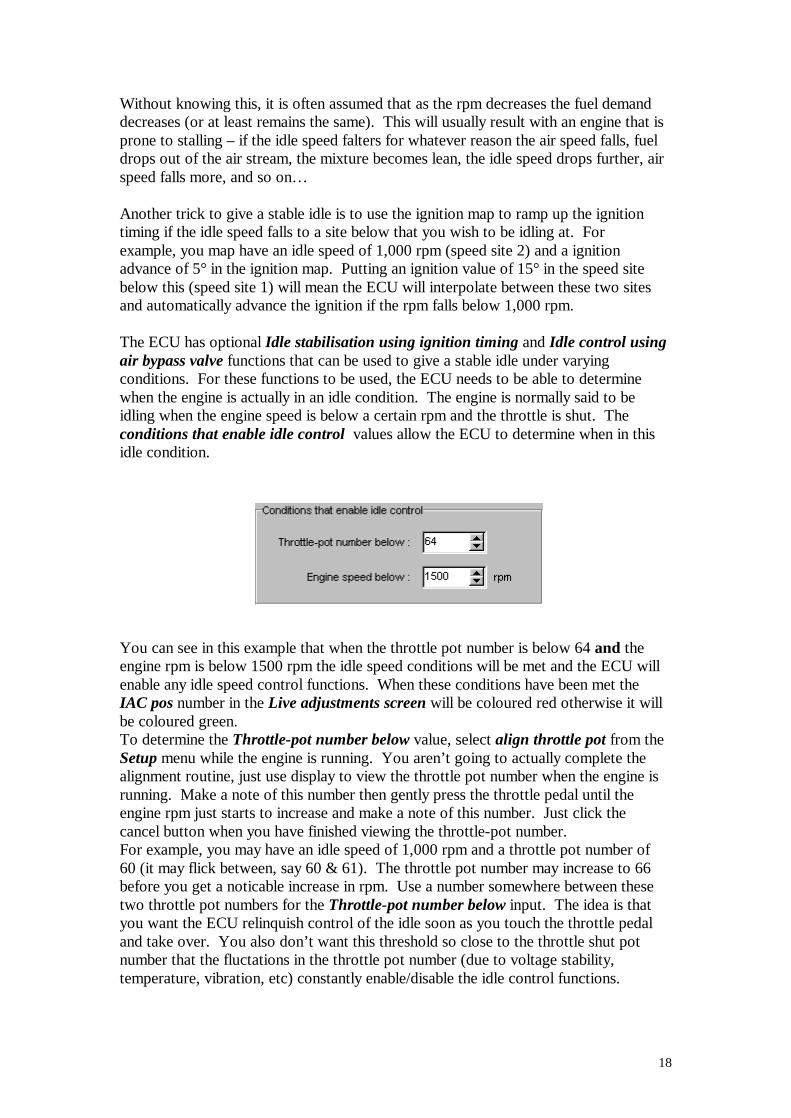
Without knowing this, it is often assumed that as the rpm decreases the fuel demand decreases (or at least remains the same). This will usually result with an engine that is prone to stalling – if the idle speed falters for whatever reason the air speed falls, fuel drops out of the air stream, the mixture becomes lean, the idle speed drops further, air speed falls more, and so on… Another trick to give a stable idle is to use the ignition map to ramp up the ignition timing if the idle speed falls to a site below that you wish to be idling at. For example, you map have an idle speed of 1,000 rpm (speed site 2) and a ignition advance of 5° in the ignition map. Putting an ignition value of 15° in the speed site below this (speed site 1) will mean the ECU will interpolate between these two sites and automatically advance the ignition if the rpm falls below 1,000 rpm. The ECU has optional Idle stabilisation using ignition timing and Idle control using air bypass valve functions that can be used to give a stable idle under varying conditions. For these functions to be used, the ECU needs to be able to determine when the engine is actually in an idle condition. The engine is normally said to be idling when the engine speed is below a certain rpm and the throttle is shut. The conditions that enable idle control values allow the ECU to determine when in this idle condition.
You can see in this example that when the throttle pot number is below 64 and the engine rpm is below 1500 rpm the idle speed conditions will be met and the ECU will enable any idle speed control functions. When these conditions have been met the IAC pos number in the Live adjustments screen will be coloured red otherwise it will be coloured green. To determine the Throttle-pot number below value, select align throttle pot from the Setup menu while the engine is running. You aren’t going to actually complete the alignment routine, just use display to view the throttle pot number when the engine is running. Make a note of this number then gently press the throttle pedal until the engine rpm just starts to increase and make a note of this number. Just click the cancel button when you have finished viewing the throttle-pot number. For example, you may have an idle speed of 1,000 rpm and a throttle pot number of 60 (it may flick between, say 60 & 61). The throttle pot number may increase to 66 before you get a noticable increase in rpm. Use a number somewhere between these two throttle pot numbers for the Throttle-pot number below input. The idea is that you want the ECU relinquish control of the idle soon as you touch the throttle pedal and take over. You also don’t want this threshold so close to the throttle shut pot number that the fluctations in the throttle pot number (due to voltage stability, temperature, vibration, etc) constantly enable/disable the idle control functions.
19
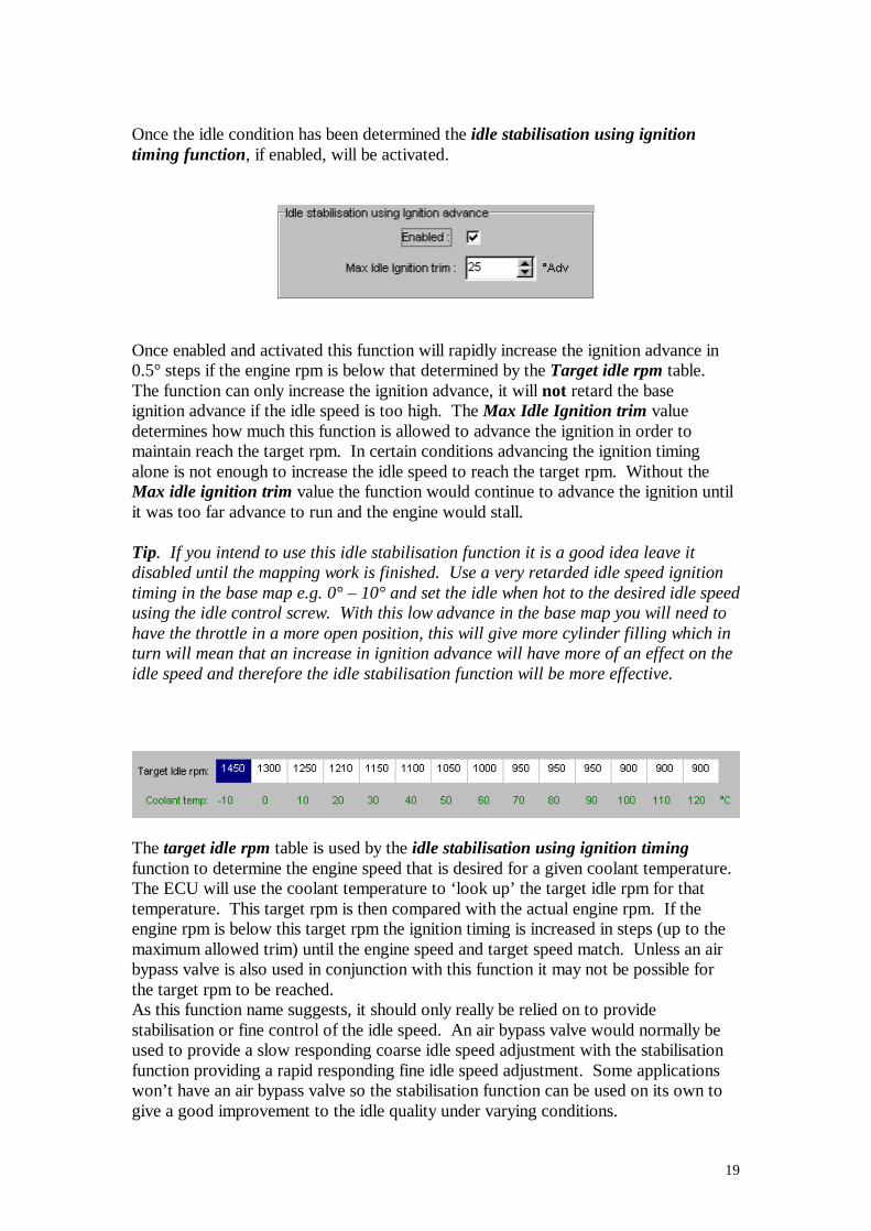
Once the idle condition has been determined the idle stabilisation using ignition timing function, if enabled, will be activated.
Once enabled and activated this function will rapidly increase the ignition advance in 0.5° steps if the engine rpm is below that determined by the Target idle rpm table. The function can only increase the ignition advance, it will not retard the base ignition advance if the idle speed is too high. The Max Idle Ignition trim value determines how much this function is allowed to advance the ignition in order to maintain reach the target rpm. In certain conditions advancing the ignition timing alone is not enough to increase the idle speed to reach the target rpm. Without the Max idle ignition trim value the function would continue to advance the ignition until it was too far advance to run and the engine would stall. Tip. If you intend to use this idle stabilisation function it is a good idea leave it disabled until the mapping work is finished. Use a very retarded idle speed ignition timing in the base map e.g. 0° – 10° and set the idle when hot to the desired idle speed using the idle control screw. With this low advance in the base map you will need to have the throttle in a more open position, this will give more cylinder filling which in turn will mean that an increase in ignition advance will have more of an effect on the idle speed and therefore the idle stabilisation function will be more effective.
The target idle rpm table is used by the idle stabilisation using ignition timing function to determine the engine speed that is desired for a given coolant temperature. The ECU will use the coolant temperature to ‘look up’ the target idle rpm for that temperature. This target rpm is then compared with the actual engine rpm. If the engine rpm is below this target rpm the ignition timing is increased in steps (up to the maximum allowed trim) until the engine speed and target speed match. Unless an air bypass valve is also used in conjunction with this function it may not be possible for the target rpm to be reached. As this function name suggests, it should only really be relied on to provide stabilisation or fine control of the idle speed. An air bypass valve would normally be used to provide a slow responding coarse idle speed adjustment with the stabilisation function providing a rapid responding fine idle speed adjustment. Some applications won’t have an air bypass valve so the stabilisation function can be used on its own to give a good improvement to the idle quality under varying conditions.
20
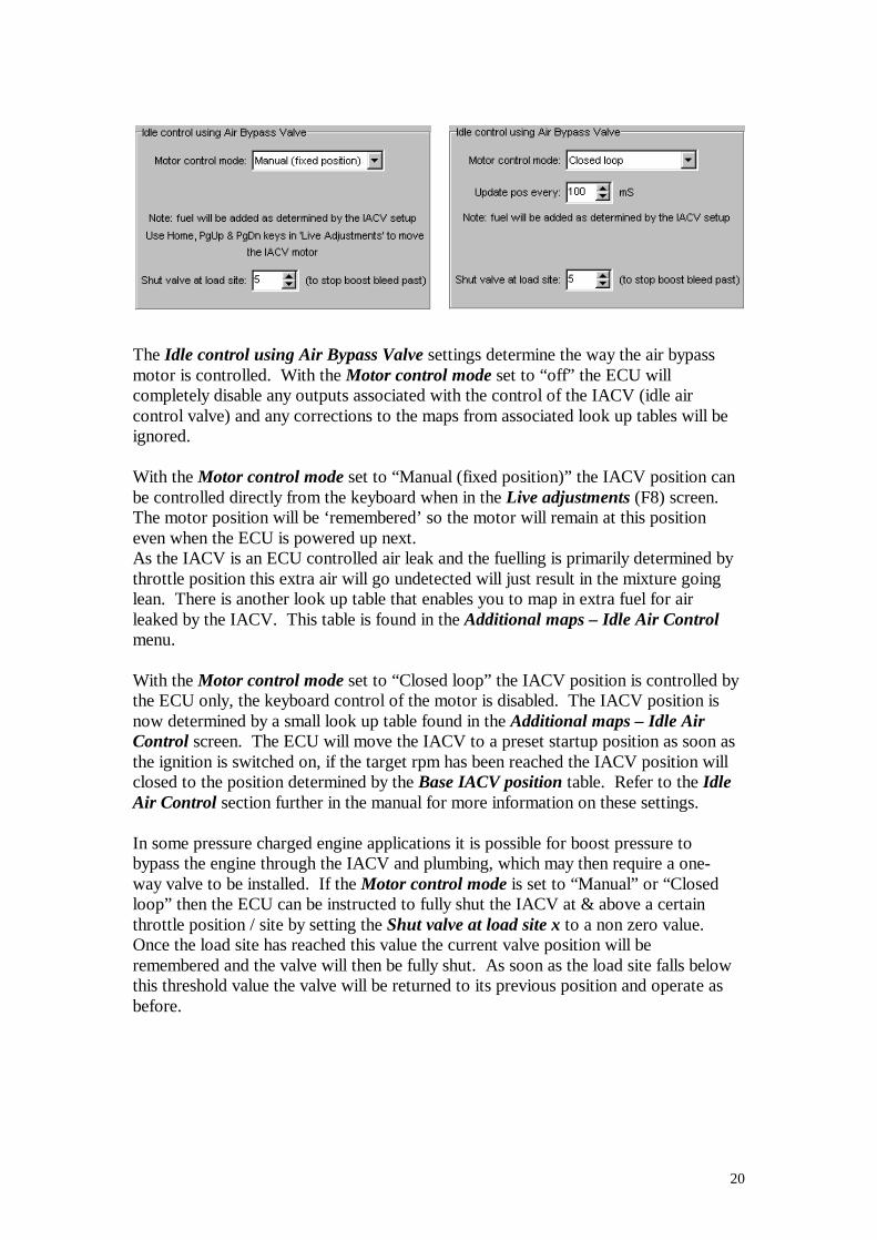
The Idle control using Air Bypass Valve settings determine the way the air bypass motor is controlled. With the Motor control mode set to “off” the ECU will completely disable any outputs associated with the control of the IACV (idle air control valve) and any corrections to the maps from associated look up tables will be ignored. With the Motor control mode set to “Manual (fixed position)” the IACV position can be controlled directly from the keyboard when in the Live adjustments (F8) screen. The motor position will be ‘remembered’ so the motor will remain at this position even when the ECU is powered up next. As the IACV is an ECU controlled air leak and the fuelling is primarily determined by throttle position this extra air will go undetected will just result in the mixture going lean. There is another look up table that enables you to map in extra fuel for air leaked by the IACV. This table is found in the Additional maps – Idle Air Control menu. With the Motor control mode set to “Closed loop” the IACV position is controlled by the ECU only, the keyboard control of the motor is disabled. The IACV position is now determined by a small look up table found in the Additional maps – Idle Air Control screen. The ECU will move the IACV to a preset startup position as soon as the ignition is switched on, if the target rpm has been reached the IACV position will closed to the position determined by the Base IACV position table. Refer to the Idle Air Control section further in the manual for more information on these settings. In some pressure charged engine applications it is possible for boost pressure to bypass the engine through the IACV and plumbing, which may then require a one-way valve to be installed. If the Motor control mode is set to “Manual” or “Closed loop” then the ECU can be instructed to fully shut the IACV at & above a certain throttle position / site by setting the Shut valve at load site x to a non zero value. Once the load site has reached this value the current valve position will be remembered and the valve will then be fully shut. As soon as the load site falls below this threshold value the valve will be returned to its previous position and operate as before.
21
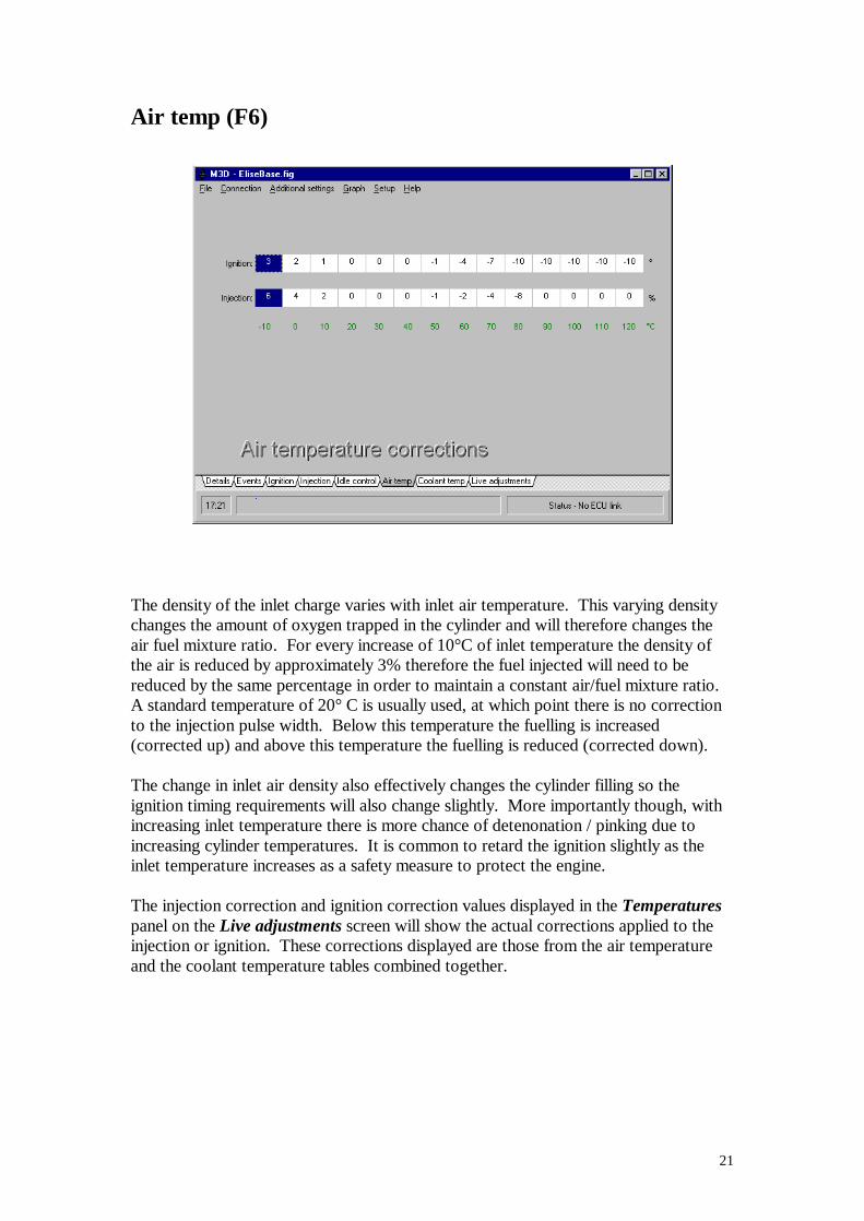
Air temp (F6)
The density of the inlet charge varies with inlet air temperature. This varying density changes the amount of oxygen trapped in the cylinder and will therefore changes the air fuel mixture ratio. For every increase of 10°C of inlet temperature the density of the air is reduced by approximately 3% therefore the fuel injected will need to be reduced by the same percentage in order to maintain a constant air/fuel mixture ratio. A standard temperature of 20° C is usually used, at which point there is no correction to the injection pulse width. Below this temperature the fuelling is increased (corrected up) and above this temperature the fuelling is reduced (corrected down). The change in inlet air density also effectively changes the cylinder filling so the ignition timing requirements will also change slightly. More importantly though, with increasing inlet temperature there is more chance of detenonation / pinking due to increasing cylinder temperatures. It is common to retard the ignition slightly as the inlet temperature increases as a safety measure to protect the engine. The injection correction and ignition correction values displayed in the Temperatures panel on the Live adjustments screen will show the actual corrections applied to the injection or ignition. These corrections displayed are those from the air temperature and the coolant temperature tables combined together.
22
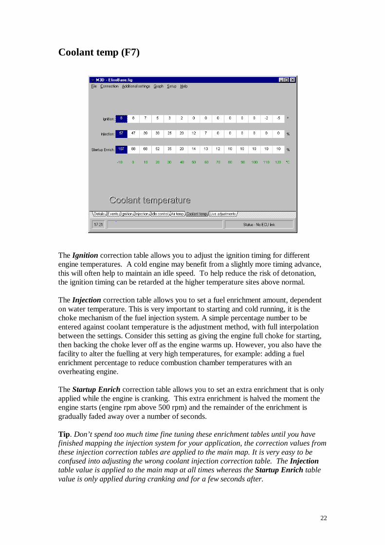
Coolant temp (F7)
The Ignition correction table allows you to adjust the ignition timing for different engine temperatures. A cold engine may benefit from a slightly more timing advance, this will often help to maintain an idle speed. To help reduce the risk of detonation, the ignition timing can be retarded at the higher temperature sites above normal. The Injection correction table allows you to set a fuel enrichment amount, dependent on water temperature. This is very important to starting and cold running, it is the choke mechanism of the fuel injection system. A simple percentage number to be entered against coolant temperature is the adjustment method, with full interpolation between the settings. Consider this setting as giving the engine full choke for starting, then backing the choke lever off as the engine warms up. However, you also have the facility to alter the fuelling at very high temperatures, for example: adding a fuel enrichment percentage to reduce combustion chamber temperatures with an overheating engine. The Startup Enrich correction table allows you to set an extra enrichment that is only applied while the engine is cranking. This extra enrichment is halved the moment the engine starts (engine rpm above 500 rpm) and the remainder of the enrichment is gradually faded away over a number of seconds. Tip. Don’t spend too much time fine tuning these enrichment tables until you have finished mapping the injection system for your application, the correction values from these injection correction tables are applied to the main map. It is very easy to be confused into adjusting the wrong coolant injection correction table. The Injection table value is applied to the main map at all times whereas the Startup Enrich table value is only applied during cranking and for a few seconds after.

23
Once the injection has been mapped, start with a fully cold engine. If you have difficulty starting the engine check that the condition of the spark plugs, these may have become fouled if the mixture is way too rich, replace/clean if necessary. While cranking you can increase/reduce the fuelling from the Live adjustments screen (using the 1,2,3 keys). When the engine is up and running clear any trim you may have by pressing the 3 key. Allow any cranking enrichment remaining to fade away, this may take a few seconds. Check how the engine runs and revs, if the mixture is over lean you will normally notice a poor pickup response when you open the throttle or ‘spitting’ in the inlet. If the mixture is over rich you will normally have black smoke from the exhaust, the spark plugs will have a tendency to foul and if excessively rich the engine will be sound rough when the throttle is opened. Use the 1 or 2 keys while in the Live adjustments screen and check for an improvement. If you need to make a change to the mixture, note the temperature and stop the engine. Increase or decrease the value in the Injection correction table at that temperature site. Reprogram the ECU with the changes and repeat the process. Note: keep a careful eye on the water temperature as you adjust the enrichment. The engine heats up quite quickly and you might find yourself adding fuel at a given temperature, not having noticed that the engine has moved on. This process may take some time and need a few attempts with a cold engine to get the correction table spot on.
24
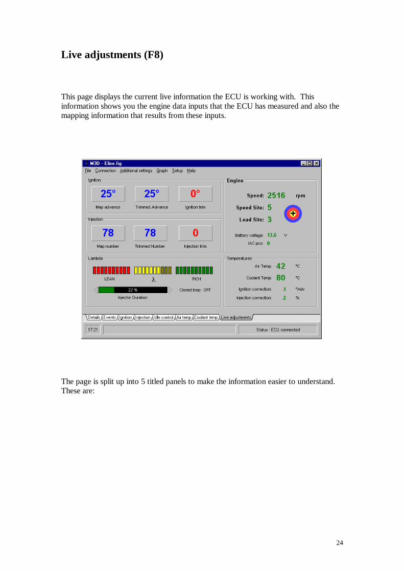
Live adjustments (F8) This page displays the current live information the ECU is working with. This information shows you the engine data inputs that the ECU has measured and also the mapping information that results from these inputs.
The page is split up into 5 titled panels to make the information easier to understand. These are:
25
Engine
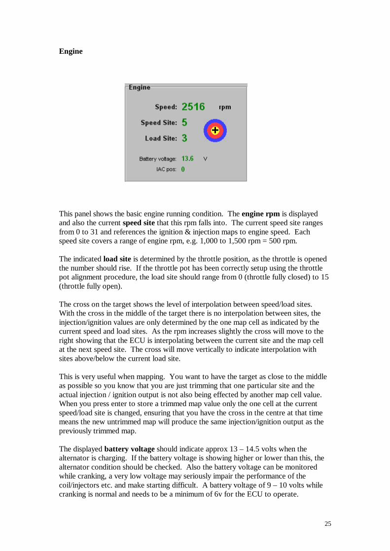
This panel shows the basic engine running condition. The engine rpm is displayed and also the current speed site that this rpm falls into. The current speed site ranges from 0 to 31 and references the ignition & injection maps to engine speed. Each speed site covers a range of engine rpm, e.g. 1,000 to 1,500 rpm = 500 rpm. The indicated load site is determined by the throttle position, as the throttle is opened the number should rise. If the throttle pot has been correctly setup using the throttle pot alignment procedure, the load site should range from 0 (throttle fully closed) to 15 (throttle fully open). The cross on the target shows the level of interpolation between speed/load sites. With the cross in the middle of the target there is no interpolation between sites, the injection/ignition values are only determined by the one map cell as indicated by the current speed and load sites. As the rpm increases slightly the cross will move to the right showing that the ECU is interpolating between the current site and the map cell at the next speed site. The cross will move vertically to indicate interpolation with sites above/below the current load site. This is very useful when mapping. You want to have the target as close to the middle as possible so you know that you are just trimming that one particular site and the actual injection / ignition output is not also being effected by another map cell value. When you press enter to store a trimmed map value only the one cell at the current speed/load site is changed, ensuring that you have the cross in the centre at that time means the new untrimmed map will produce the same injection/ignition output as the previously trimmed map. The displayed battery voltage should indicate approx 13 – 14.5 volts when the alternator is charging. If the battery voltage is showing higher or lower than this, the alternator condition should be checked. Also the battery voltage can be monitored while cranking, a very low voltage may seriously impair the performance of the coil/injectors etc. and make starting difficult. A battery voltage of 9 – 10 volts while cranking is normal and needs to be a minimum of 6v for the ECU to operate.

26
The IAC pos indicates the current position of the Idle AirBypass Control Valve (if fitted). The colour of this number also indicates if the ECU has determined the engine is idling and therefore allowing the idle control functions to operate (if they are enabled). If the IAC pos number is coloured red the ECU is in idle control mode otherwise it is coloured green. The engine rpm and the throttle pot number are used by the ECU to determine if the engine is idling, these settings are found in the Idle speed control screen (F5). Depending on the current operating mode of the IAC valve the motor can be moved manually from the keyboard from the Live adjustments screen. Pressing home will move the motor to the fully closed position (IAC pos: 0). Pressing the Page Up or Page Down keys (PgUp/PgDn) will open/close the valve by one step. Pressing the shift key at the same time as PgUp/PgDn will move the motor in steps of 10.
27
Temperatures
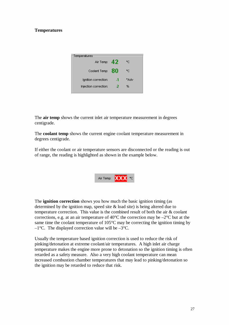
The air temp shows the current inlet air temperature measurement in degrees centigrade. The coolant temp shows the current engine coolant temperature measurement in degrees centigrade. If either the coolant or air temperature sensors are disconnected or the reading is out of range, the reading is highlighted as shown in the example below.
The ignition correction shows you how much the basic ignition timing (as determined by the ignition map, speed site & load site) is being altered due to temperature correction. This value is the combined result of both the air & coolant corrections, e.g. at an air temperature of 40°C the correction may be –2°C but at the same time the coolant temperature of 105°C may be correcting the ignition timing by –1°C. The displayed correction value will be –3°C. Usually the temperature based ignition correction is used to reduce the risk of pinking/detonation at extreme coolant/air temperatures. A high inlet air charge temperature makes the engine more prone to detonation so the ignition timing is often retarded as a safety measure. Also a very high coolant temperature can mean increased combustion chamber temperatures that may lead to pinking/detonation so the ignition may be retarded to reduce that risk.

28
The displayed injection correction value is derived in exactly the same way. It is a combination of the coolant temperature correction & air temperature correction, but does not include the accel fuelling correction or the cranking enrichment. In normal conditions the injection correction value will be a positive value that decreases as the coolant temperature increases, when the engine reaches normal running temperature, the correction will be zero. Because the density of the air entering the engine (& therefore the volume of oxygen) varies with the inlet air temperature, the injected fuel quantity can be corrected to maintain a constant mixture ratio. As the inlet temperature rises the density of the air reduces, if the injected fuel quantity is not corrected, the mixture ratio will become richer. Also the reverse is true, a cool inlet charge temperature means a denser inlet charge (more oxygen) so the mixture ratio will become lean. Note: the map values that compensate for air temperature/injection correction do not normally need to be altered; the relationship is constant regardless of engine. Most base maps supplied on disk will have these values pre-set although they can be zero’d if an air temperature sensor is not used.
29
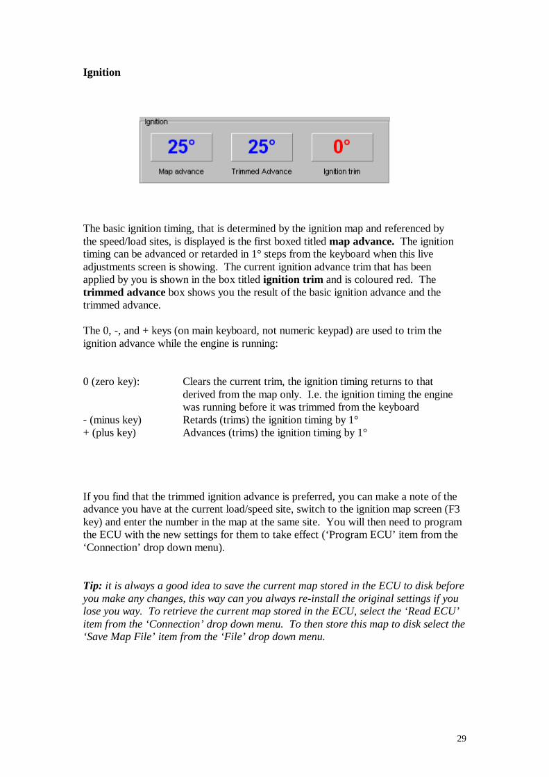
Ignition
The basic ignition timing, that is determined by the ignition map and referenced by the speed/load sites, is displayed is the first boxed titled map advance. The ignition timing can be advanced or retarded in 1° steps from the keyboard when this live adjustments screen is showing. The current ignition advance trim that has been applied by you is shown in the box titled ignition trim and is coloured red. The trimmed advance box shows you the result of the basic ignition advance and the trimmed advance. The 0, -, and + keys (on main keyboard, not numeric keypad) are used to trim the ignition advance while the engine is running: 0 (zero key): Clears the current trim, the ignition timing returns to that
derived from the map only. I.e. the ignition timing the engine was running before it was trimmed from the keyboard
- (minus key) Retards (trims) the ignition timing by 1° + (plus key) Advances (trims) the ignition timing by 1° If you find that the trimmed ignition advance is preferred, you can make a note of the advance you have at the current load/speed site, switch to the ignition map screen (F3 key) and enter the number in the map at the same site. You will then need to program the ECU with the new settings for them to take effect (‘Program ECU’ item from the ‘Connection’ drop down menu). Tip: it is always a good idea to save the current map stored in the ECU to disk before you make any changes, this way can you always re-install the original settings if you lose you way. To retrieve the current map stored in the ECU, select the ‘Read ECU’ item from the ‘Connection’ drop down menu. To then store this map to disk select the ‘Save Map File’ item from the ‘File’ drop down menu.

30
Another way to store your trimmed advance in the map is to press enter when at the speed/load site you want to change. When you press enter, this trimmed advance will be programmed into the ECU’s map at the speed/load site you selected. The ECU’s map will now be changed in the same way it would have been if you had used the previous method. The map advance will now be what was the trimmed advance. The ignition trim value will also be automatically zeroed to prevent the new-programmed map site being trimmed again. At the same time the map site in the ECU is programmed, the map stored in the PC will also be programmed. Both the map store in the ECU & the PC will be the same. If you switch to the ignition map (F3) you will see that the programmed site will be coloured red to indicate that this site was programmed from the live adjustments screen.
31
Injection
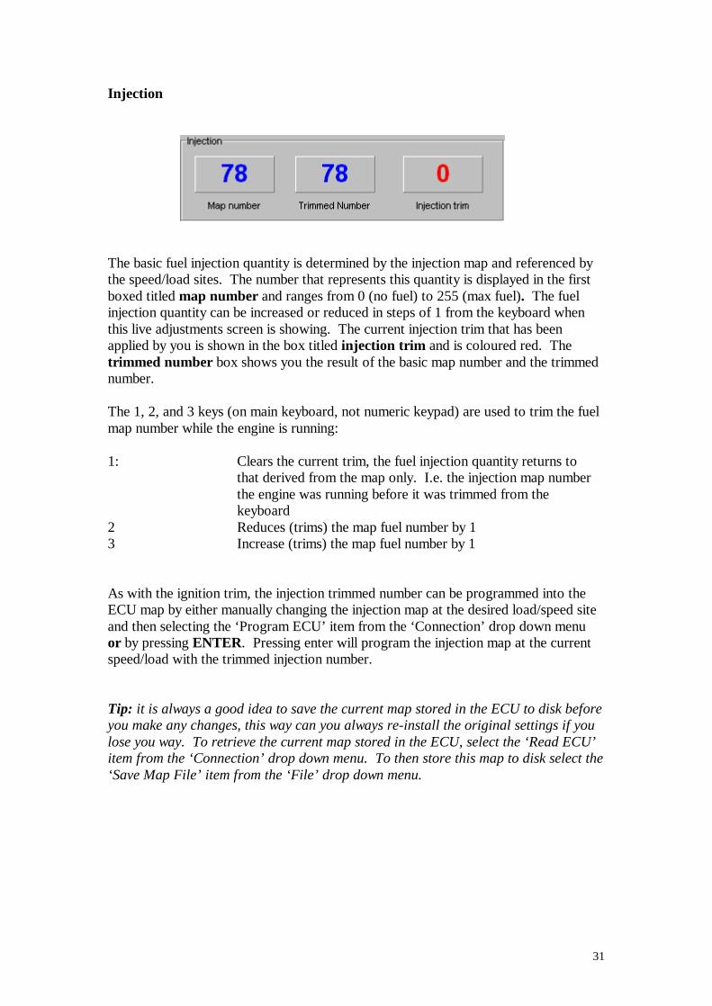
The basic fuel injection quantity is determined by the injection map and referenced by the speed/load sites. The number that represents this quantity is displayed in the first boxed titled map number and ranges from 0 (no fuel) to 255 (max fuel). The fuel injection quantity can be increased or reduced in steps of 1 from the keyboard when this live adjustments screen is showing. The current injection trim that has been applied by you is shown in the box titled injection trim and is coloured red. The trimmed number box shows you the result of the basic map number and the trimmed number. The 1, 2, and 3 keys (on main keyboard, not numeric keypad) are used to trim the fuel map number while the engine is running: 1: Clears the current trim, the fuel injection quantity returns to
that derived from the map only. I.e. the injection map number the engine was running before it was trimmed from the keyboard
2 Reduces (trims) the map fuel number by 1 3 Increase (trims) the map fuel number by 1 As with the ignition trim, the injection trimmed number can be programmed into the ECU map by either manually changing the injection map at the desired load/speed site and then selecting the ‘Program ECU’ item from the ‘Connection’ drop down menu or by pressing ENTER. Pressing enter will program the injection map at the current speed/load with the trimmed injection number. Tip: it is always a good idea to save the current map stored in the ECU to disk before you make any changes, this way can you always re-install the original settings if you lose you way. To retrieve the current map stored in the ECU, select the ‘Read ECU’ item from the ‘Connection’ drop down menu. To then store this map to disk select the ‘Save Map File’ item from the ‘File’ drop down menu.
32
Lambda
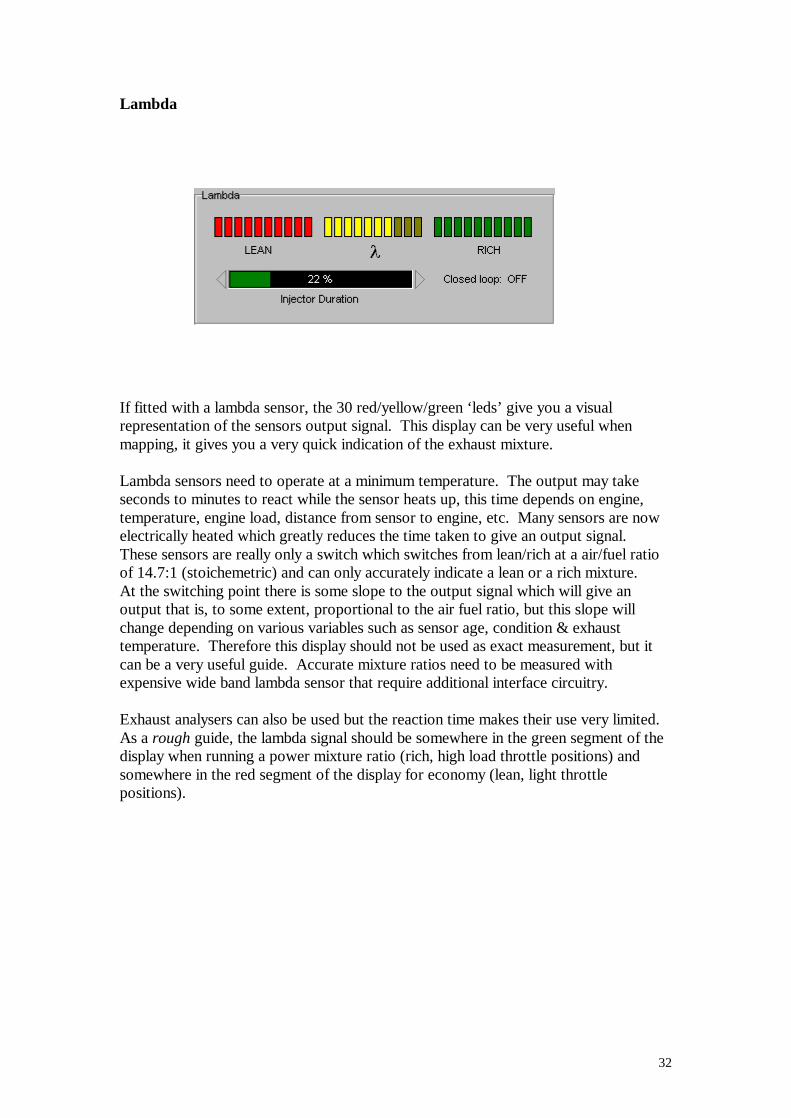
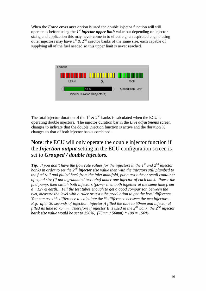
If fitted with a lambda sensor, the 30 red/yellow/green ‘leds’ give you a visual representation of the sensors output signal. This display can be very useful when mapping, it gives you a very quick indication of the exhaust mixture. Lambda sensors need to operate at a minimum temperature. The output may take seconds to minutes to react while the sensor heats up, this time depends on engine, temperature, engine load, distance from sensor to engine, etc. Many sensors are now electrically heated which greatly reduces the time taken to give an output signal. These sensors are really only a switch which switches from lean/rich at a air/fuel ratio of 14.7:1 (stoichemetric) and can only accurately indicate a lean or a rich mixture. At the switching point there is some slope to the output signal which will give an output that is, to some extent, proportional to the air fuel ratio, but this slope will change depending on various variables such as sensor age, condition & exhaust temperature. Therefore this display should not be used as exact measurement, but it can be a very useful guide. Accurate mixture ratios need to be measured with expensive wide band lambda sensor that require additional interface circuitry. Exhaust analysers can also be used but the reaction time makes their use very limited. As a rough guide, the lambda signal should be somewhere in the green segment of the display when running a power mixture ratio (rich, high load throttle positions) and somewhere in the red segment of the display for economy (lean, light throttle positions).

33
Information relevant to the lambda display is also close by. The injection duration bar shows you how hard the injectors are being worked. The ECU calculates the percentage of the available time the injectors are on for (duration %) and this is displayed in the duration bar. At the extremes of injector duration i.e. very short or long opening pulse, the duration bar changes colour as a warning. Below 10% duration, the bar will turn yellow. Above 85% duration the bar will turn red and at or above 100% the triangular led to the right of the bar will flash red/yellow. At the extremes of duration the turn on/off characteristics of the injector have a greater effect on the accuracy on the quantity of fuel injected. This isn’t such an issue with the way the M3DK system works (where the pulse width is directly determined by lookup tables rather than calculated in order to give a measured quantity of fuel). It is a good idea to size your injectors or set the fuel pressure so that you are making best use of the injectors flow rate. Ideally you want the maximum duration to be approx 85 – 90%. Using injectors that are too big will mean that the injector pulse widths will be smaller and at around idle speed the resolution of the injector pulse may make it difficult to get a good exhaust mixture. If you find that the injectors are too small you can check/increase the fuel pressure to provide more fuel flow. Fuel pressure should normally be in the region of 2.5 to 4.0 bar, fuel atomisation, spray pattern and other factors means it is advisable to keep the fuel pressure in this region. Using the Injection Scaling function will enable the system to re-scale the map to compensate for changes you may want to make to the fuel pressure or injector size without requiring a complete re-map of the system.
34
Additional maps
Accel fuelling
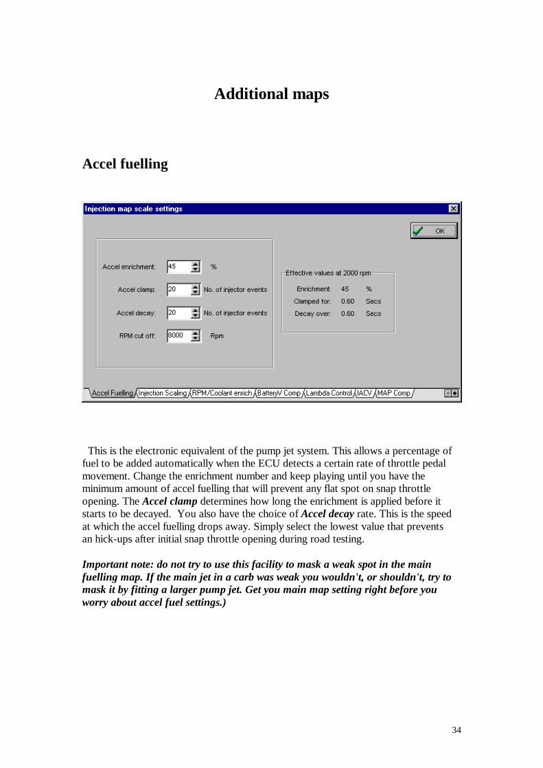
This is the electronic equivalent of the pump jet system. This allows a percentage of fuel to be added automatically when the ECU detects a certain rate of throttle pedal movement. Change the enrichment number and keep playing until you have the minimum amount of accel fuelling that will prevent any flat spot on snap throttle opening. The Accel clamp determines how long the enrichment is applied before it starts to be decayed. You also have the choice of Accel decay rate. This is the speed at which the accel fuelling drops away. Simply select the lowest value that prevents an hick-ups after initial snap throttle opening during road testing. Important note: do not try to use this facility to mask a weak spot in the main fuelling map. If the main jet in a carb was weak you wouldn't, or shouldn't, try to mask it by fitting a larger pump jet. Get you main map setting right before you worry about accel fuel settings.)
35
Injection Scaling function
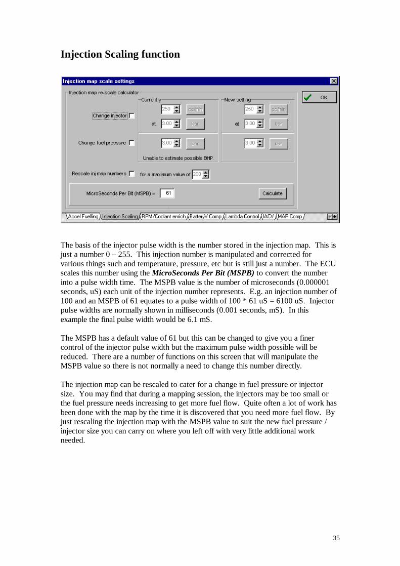
The basis of the injector pulse width is the number stored in the injection map. This is just a number 0 – 255. This injection number is manipulated and corrected for various things such and temperature, pressure, etc but is still just a number. The ECU scales this number using the MicroSeconds Per Bit (MSPB) to convert the number into a pulse width time. The MSPB value is the number of microseconds (0.000001 seconds, uS) each unit of the injection number represents. E.g. an injection number of 100 and an MSPB of 61 equates to a pulse width of 100 * 61 uS = 6100 uS. Injector pulse widths are normally shown in milliseconds (0.001 seconds, mS). In this example the final pulse width would be 6.1 mS. The MSPB has a default value of 61 but this can be changed to give you a finer control of the injector pulse width but the maximum pulse width possible will be reduced. There are a number of functions on this screen that will manipulate the MSPB value so there is not normally a need to change this number directly. The injection map can be rescaled to cater for a change in fuel pressure or injector size. You may find that during a mapping session, the injectors may be too small or the fuel pressure needs increasing to get more fuel flow. Quite often a lot of work has been done with the map by the time it is discovered that you need more fuel flow. By just rescaling the injection map with the MSPB value to suit the new fuel pressure / injector size you can carry on where you left off with very little additional work needed.
36
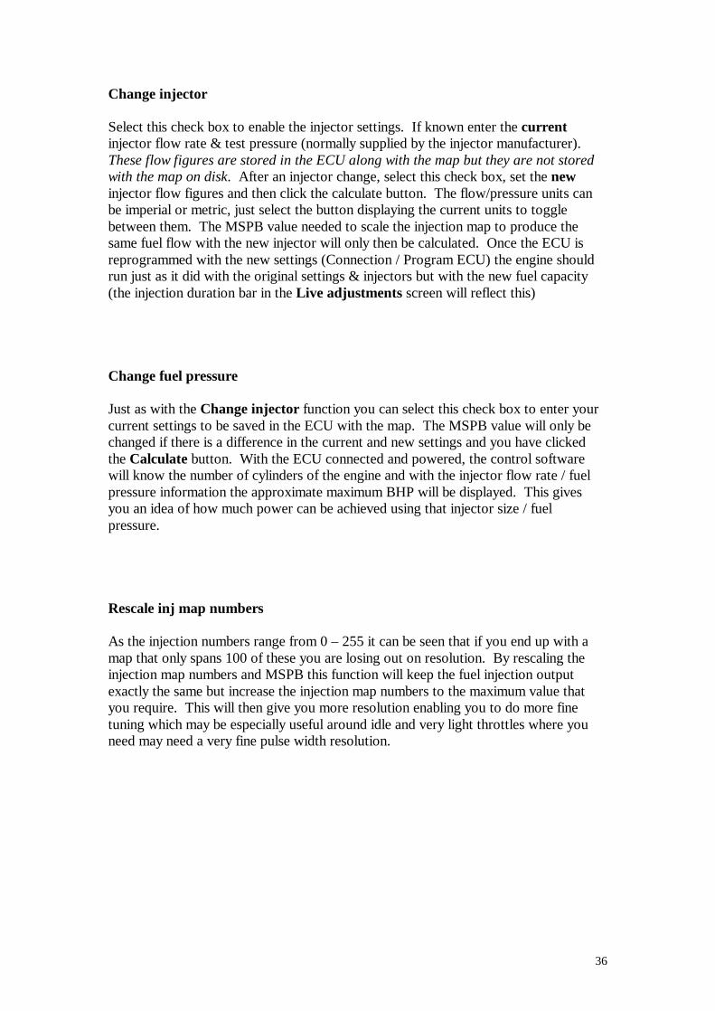
Change injector Select this check box to enable the injector settings. If known enter the current injector flow rate & test pressure (normally supplied by the injector manufacturer). These flow figures are stored in the ECU along with the map but they are not stored with the map on disk. After an injector change, select this check box, set the new injector flow figures and then click the calculate button. The flow/pressure units can be imperial or metric, just select the button displaying the current units to toggle between them. The MSPB value needed to scale the injection map to produce the same fuel flow with the new injector will only then be calculated. Once the ECU is reprogrammed with the new settings (Connection / Program ECU) the engine should run just as it did with the original settings & injectors but with the new fuel capacity (the injection duration bar in the Live adjustments screen will reflect this) Change fuel pressure Just as with the Change injector function you can select this check box to enter your current settings to be saved in the ECU with the map. The MSPB value will only be changed if there is a difference in the current and new settings and you have clicked the Calculate button. With the ECU connected and powered, the control software will know the number of cylinders of the engine and with the injector flow rate / fuel pressure information the approximate maximum BHP will be displayed. This gives you an idea of how much power can be achieved using that injector size / fuel pressure. Rescale inj map numbers As the injection numbers range from 0 – 255 it can be seen that if you end up with a map that only spans 100 of these you are losing out on resolution. By rescaling the injection map numbers and MSPB this function will keep the fuel injection output exactly the same but increase the injection map numbers to the maximum value that you require. This will then give you more resolution enabling you to do more fine tuning which may be especially useful around idle and very light throttles where you need may need a very fine pulse width resolution.

37
For example, with a maximum injection map number of 100 and an MSPB of 61 the maximum pulse width will be 6.1 mS and each unit will be 0.061 mS. When trimming the map in the Live adjustments screen, each tap of the key will change the pulse width by 0.061 mS. If you choose to rescale the injection map numbers for a maximum value of 200 (click the Rescale inj map numbers check box, set the to a maximum value of to 200, click calculate, program ECU) the MPSB will be recalculated to 30.5 and rounded to 31 (fractional values not allowed). The maximum pulse width will now be 6.2 mS and each unit will be 0.031 mS. You can see that the injection resolution has doubled. Due to rounding errors the final injection output may be affected slightly (1.5% in this case) so the map may need to be checked. Tip. Before using this function, make sure all unused map sites above the maximum rpm you have mapped to are not going to effect the final scaling, these numbers may be left over from a base map you used initially. To be sure, block the area above which the engine won’t be running and fill them to zero.
38
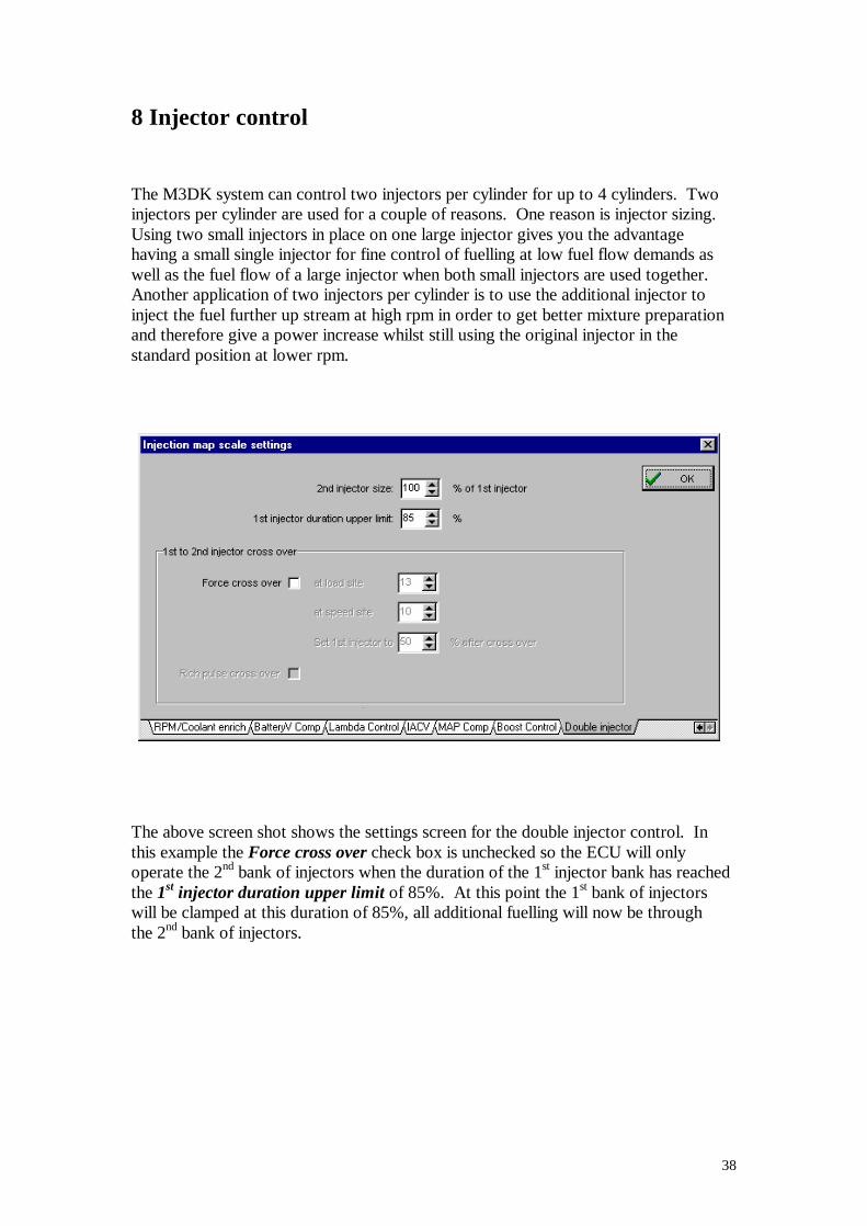
8 Injector control The M3DK system can control two injectors per cylinder for up to 4 cylinders. Two injectors per cylinder are used for a couple of reasons. One reason is injector sizing. Using two small injectors in place on one large injector gives you the advantage having a small single injector for fine control of fuelling at low fuel flow demands as well as the fuel flow of a large injector when both small injectors are used together. Another application of two injectors per cylinder is to use the additional injector to inject the fuel further up stream at high rpm in order to get better mixture preparation and therefore give a power increase whilst still using the original injector in the standard position at lower rpm.
The above screen shot shows the settings screen for the double injector control. In this example the Force cross over check box is unchecked so the ECU will only operate the 2nd bank of injectors when the duration of the 1st injector bank has reached the 1st injector duration upper limit of 85%. At this point the 1st bank of injectors will be clamped at this duration of 85%, all additional fuelling will now be through the 2nd bank of injectors.
39
The ECU will determine the fuel needed above the limit of the 1st bank of injectors and then scale this duration using the 2nd injector size value. If the injectors of the 1st and 2nd banks are of the same size then this value should be 100%. If the 2nd bank injectors are twice the size this value should be 200%. This method of operation is often used with a pressure charged engine with a high bhp / litre. This allows you to use a small 1st injector bank size to give good fuel control at idle and low loads with an additional bank of injectors to provide the extra fuel needed for high power output.
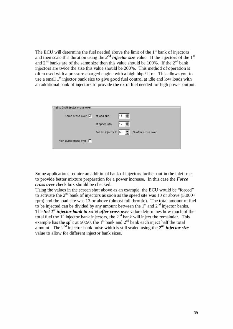
Some applications require an additional bank of injectors further out in the inlet tract to provide better mixture preparation for a power increase. In this case the Force cross over check box should be checked. Using the values in the screen shot above as an example, the ECU would be “forced” to activate the 2nd bank of injectors as soon as the speed site was 10 or above (5,000+ rpm) and the load site was 13 or above (almost full throttle). The total amount of fuel to be injected can be divided by any amount between the 1st and 2nd injector banks. The Set 1st injector bank to xx % after cross over value determines how much of the total fuel the 1st injector bank injectors, the 2nd bank will inject the remainder. This example has the split at 50:50, the 1st bank and 2nd bank each inject half the total amount. The 2nd injector bank pulse width is still scaled using the 2nd injector size value to allow for different injector bank sizes.
40
When the Force cross over option is used the double injector function will still operate as before using the 1st injector upper limit value but depending on injector sizing and application this may never come in to effect e.g. an aspirated engine using outer injectors may have 1st & 2nd injector banks of the same size, each capable of supplying all of the fuel needed so this upper limit is never reached.
The total injector duration of the 1st & 2nd banks is calculated when the ECU is operating double injectors. The injector duration bar in the Live adjustments screen changes to indicate that the double injection function is active and the duration % changes to that of both injector banks combined. Note: the ECU will only operate the double injector function if the Injection output setting in the ECU configuration screen is set to Grouped / double injectors. Tip. If you don’t have the flow rate values for the injectors in the 1st and 2nd injector banks in order to set the 2nd injector size value then with the injectors still plumbed to the fuel rail and pulled back from the inlet manifold, put a test tube or small container of equal size (if not a graduated test tube) under one injector of each bank. Power the fuel pump, then switch both injectors (power then both together at the same time from a +12v & earth). Fill the test tubes enough to get a good comparison between the two, measure the level with a ruler or test tube graduation to get the level difference. You can use this difference to calculate the % difference between the two injectors. E.g. after 30 seconds of injection, injector A filled the tube to 50mm and injector B filled its tube to 75mm. Therefore if injector B is used in the 2nd bank, the 2nd injector bank size value would be set to 150%, (75mm / 50mm) * 100 = 150%
41
Rover K-series Immobiliser function
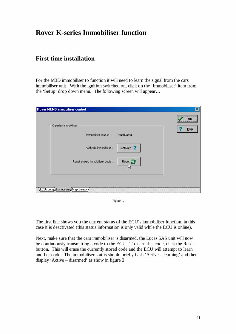
First time installation For the M3D immobiliser to function it will need to learn the signal from the cars immobiliser unit. With the ignition switched on, click on the ‘Immobiliser’ item from the ‘Setup’ drop down menu. The following screen will appear…
Figure 1.
The first line shows you the current status of the ECU’s immobiliser function, in this case it is deactivated (this status information is only valid while the ECU is online). Next, make sure that the cars immobiliser is disarmed, the Lucas 5AS unit will now be continuously transmitting a code to the ECU. To learn this code, click the Reset button. This will erase the currently stored code and the ECU will attempt to learn another code. The immobiliser status should briefly flash ‘Active – learning’ and then display ‘Active – disarmed’ as show in figure 2.
42
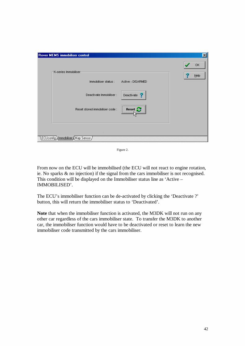
Figure 2.
From now on the ECU will be immobilised (the ECU will not react to engine rotation, ie. No sparks & no injection) if the signal from the cars immobiliser is not recognised. This condition will be displayed on the Immobiliser status line as ‘Active – IMMOBILISED’. The ECU’s immobiliser function can be de-activated by clicking the ‘Deactivate ?’ button, this will return the immobiliser status to ‘Deactivated’. Note that when the immobiliser function is activated, the M3DK will not run on any other car regardless of the cars immobiliser state. To transfer the M3DK to another car, the immobiliser function would have to be deactivated or reset to learn the new immobiliser code transmitted by the cars immobiliser.
43
Trigger setup and alignment Distributor based trigger With the advent of high speed electronics it is possible to control the ignition timing without any moving advance mechanism. Depending on the distributor type you may need to modify it to make it suitable for use as an ECU trigger. Some later distributors are designed for this purpose, they have no mechanical advance mechanisms and the rotor arm alignment is preset. Distributors with centrifugal and/or vacuum advance mechanisms need to be modified to lock these mechanisms in place so a fixed reference signal will be generated (the mechanism can be held in place with lock wire, araldite, weld, etc) The M3D ignition system takes a signal from your distributor and holds on to it until the time is right to fire the ignition coil. For example, with the distributor set to give a reference trigger of 66° BTDC and a mapped ignition timing of 20° BTDC, the ECU will wait for 66 – 20 = 46° before giving the spark. The ECU needs time to respond to the reference trigger signal and time to calculate the necessary delay so the reference trigger must be more advanced than the mapped ignition timing range – the ECU has a default reference point of 66° BTDC. Allow at least 5 degrees more than the maximum advance you wish to use, e.g. for a maximum of 50° advance set the reference to at least 55°. When modifying the distributor you also need to check the alignment of the rotor arm in relation to the distributor cap. With the engine at TDC no. 1 check the position of the rotor arm in relation to the HT lead connection in the distributor cap – ideally you want the trailing edge of the rotor arm to be in line with this point. Remember that the distributor needs to trigger the ECU at a very advanced figure, e.g. 66° advance, whilst having the rotor arm line up with the HT lead point in the cap when at TDC. If using a Lumenition optical sensor just move the base plate / optical sensor until the trailing edge of the plastic blade is in line with the sensor centre line (just cutting the beam). As the plastic blade is approx 30° wide (60 crank degrees) and the ECU triggers from the leading edge, this should equate to a reference point of approximately 60° BTDC. Once running you can check the advance with a timing light and set the distributor position exactly. With other sensor types you will need to turn the engine back 66 degrees (33 distributor degrees). Now move the base plate / sensor so the sensor is just being triggered. Note The position of the pickup sensor in relation to the distributor body will determine the rotor arm to distributor cap alignment. Rotating the distributor or adjusting where you lock the centrifugal advance weights won’t affect this alignment.
44
When configured to trigger from a distributor signal the ECU can be set to sense a digital switching signal (e.g. Bosch hall-effect or Lumenition optical sensors) or an AC signal from an inductive sensor. Note that when using the Lumenition optical sensor you do not need the Lumenition amplifier module, the ECU has it’s own ignition amplifiers built in. The distributor sensor wiring will depend on the sensor type used… • Hall Effect (e.g. Bosch) If a Hall Effect trigger is to be used then it will have three connections. The distributor plugs are usually marked with + 0 - The “+” connection is the supply voltage to the sensor. You can use the ECU +8v (pin 14) output to power the sensor or wire to an ignition controlled +12v. The “– “connection is the sensor earth, connect this to the ECU sensor earth (pin 30). The “0” connection is the sensor signal, connect this to the ECU main trigger input (pin 31). The Lumenition wiring is the same but the connections are identified by the wire colour.
Red = + supply voltage (important!, only connect to ECU +8v, pin 14) Blue = 0 sensor signal (ECU signal, pin 31) Black = - sensor earth (ECU sensor earth, pin 30)
l Inductive trigger (e.g. Peugeot or Rover V8) The inductive sensor has two signal wires that need to be wired to the main trigger sensor input (pin 31) and the main trigger sensor earth (pin 30). The signal from this sensor is very sensitive to electrical interference so if possible route the cables away from sources of noise (alternator, ignition coils, etc). Also it is a good idea to use a shielded two core cable with the shielding earthed at one end (e.g. the ECU earth).
45
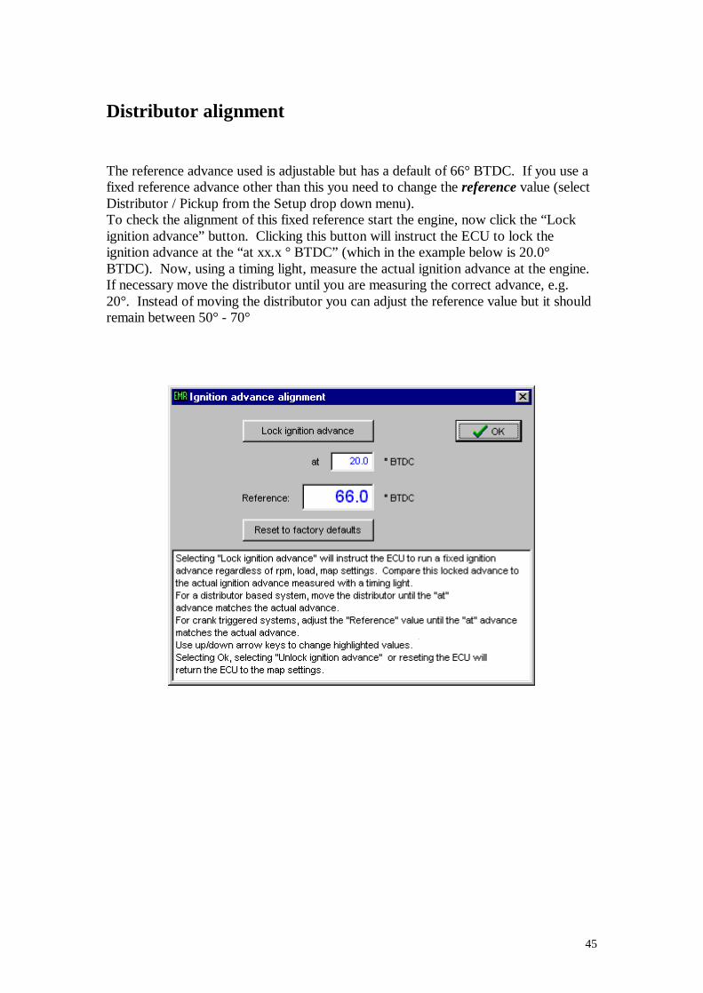
Distributor alignment The reference advance used is adjustable but has a default of 66° BTDC. If you use a fixed reference advance other than this you need to change the reference value (select Distributor / Pickup from the Setup drop down menu). To check the alignment of this fixed reference start the engine, now click the “Lock ignition advance” button. Clicking this button will instruct the ECU to lock the ignition advance at the “at xx.x ° BTDC” (which in the example below is 20.0° BTDC). Now, using a timing light, measure the actual ignition advance at the engine. If necessary move the distributor until you are measuring the correct advance, e.g. 20°. Instead of moving the distributor you can adjust the reference value but it should remain between 50° - 70°

46
Crankshaft based trigger The Emerald ECU can trigger from a multi-tooth crankshaft based signal. Many modern engines have a crankshaft/flywheel mounted trigger arrangement. Different manufacturers have adopted various patterns and types but the most common types are the Ford 36-1 (36 teeth, one of which is missing) or the Bosch 60-2 (60 teeth, two of which are missing). Other notable patterns are the three patterns used by Rover (36-2, and two types of 36-4) and the 12-tooth pattern used by Honda. Honda’s arrangement is a little different in that there is not a missing or extra tooth to indicate TDC; instead another cam-mounted trigger is used to indicate TDC. The Honda 12+1 pattern can be a 12-tooth trigger on the crankshaft or a 24-tooth trigger on the camshaft; the resulting signal is no different as far as the ECU is concerned. When the main trigger type in the ECU’s configuration setup is set to “crank” you will also need to set the sensor “type” and the “pattern”. The type is either digital or inductive depending on the sensor. Most majority of manufacturers use an inductive sensor, this generates a varying voltage as the trigger teeth pass the sensor. One exception is the late Siemens sensor that is used on some Vauxhall/GM Ecotek engines. This is a 3-wire digital sensor – electronics inside the sensor convert the analogue voltages to a digital signal. The advantage with this sensor type is that the digital signal is very robust and not as susceptible to interference as the low level inductive signal. When wiring an inductive sensor it is advisable to use a two-core shielded cable between the sensor and the ECU. Some sensors have a short flying lead with a 3-pin connector. Two connections will be for the sensor and the third for the shielding. The shielding should be earthed at one end only, preferably at the ECU end and to the ECU’s main earth wire.
47
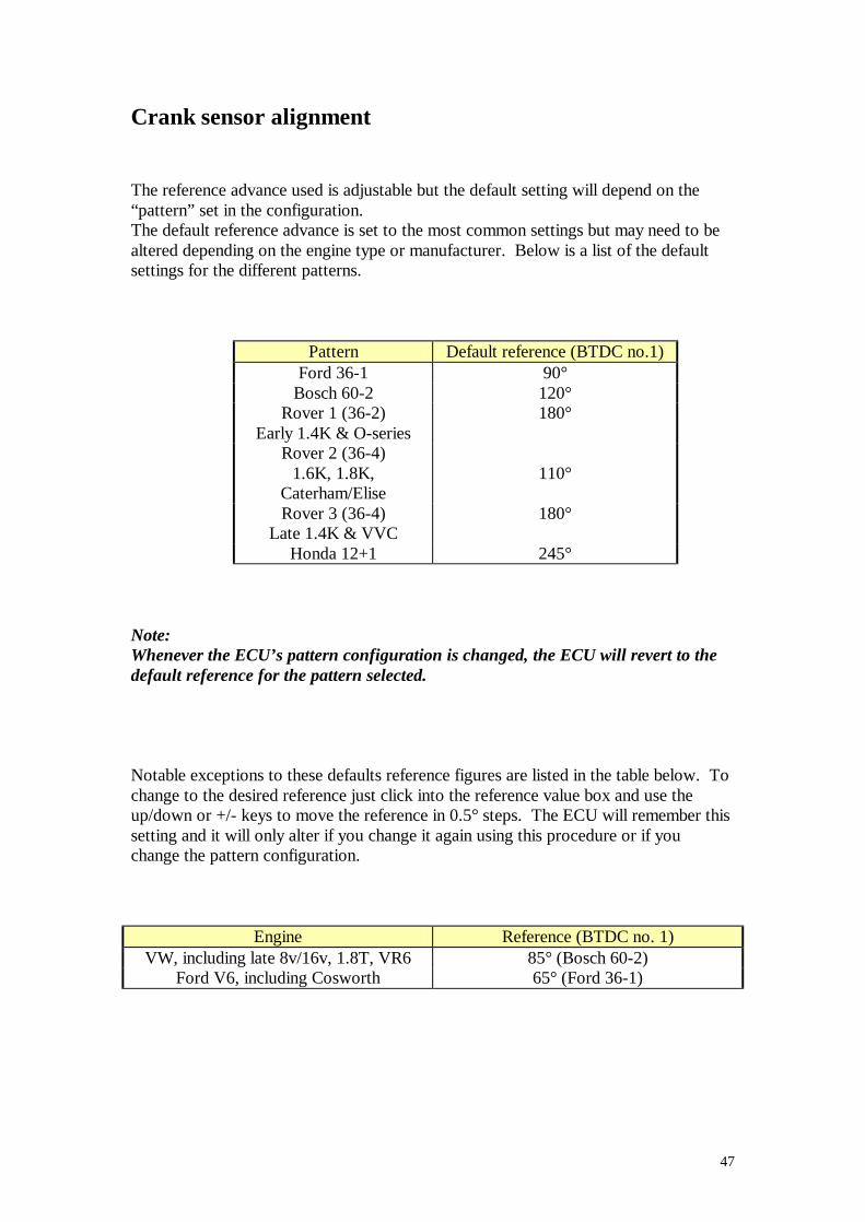
Crank sensor alignment The reference advance used is adjustable but the default setting will depend on the “pattern” set in the configuration. The default reference advance is set to the most common settings but may need to be altered depending on the engine type or manufacturer. Below is a list of the default settings for the different patterns.
Pattern Default reference (BTDC no.1) Ford 36-1 90°
Bosch 60-2 120° Rover 1 (36-2)
Early 1.4K & O-series 180°
Rover 2 (36-4) 1.6K, 1.8K,
Caterham/Elise
110°
Rover 3 (36-4) Late 1.4K & VVC
180°
Honda 12+1 245° Note: Whenever the ECU’s pattern configuration is changed, the ECU will revert to the default reference for the pattern selected. Notable exceptions to these defaults reference figures are listed in the table below. To change to the desired reference just click into the reference value box and use the up/down or +/- keys to move the reference in 0.5° steps. The ECU will remember this setting and it will only alter if you change it again using this procedure or if you change the pattern configuration.
Engine Reference (BTDC no. 1) VW, including late 8v/16v, 1.8T, VR6 85° (Bosch 60-2)
Ford V6, including Cosworth 65° (Ford 36-1)
48
If you are retro fitting a crank trigger wheel to an engine you will need to either set the trigger wheel / sensor relationship to one of the default settings or work out this reference value so it can be set in the “Ignition advance alignment” screen. If at all possible it is preferable to set the trigger wheel to a default position, this removes the chance of disturbing the reference figure if the pattern configuration setting is changed by accident at a later date. Any error in position measurement can be dialled out once the engine is running. Locking the ignition timing and comparing this to a measured ignition advance will show you the error and allow you to adjust the reference figure to eliminate it.
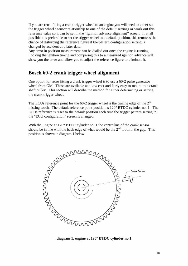
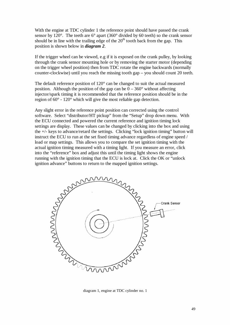
Bosch 60-2 crank trigger wheel alignment One option for retro fitting a crank trigger wheel is to use a 60-2 pulse generator wheel from GM. These are available at a low cost and fairly easy to mount to a crank shaft pulley. This section will describe the method for either determining or setting the crank trigger wheel. The ECUs reference point for the 60-2 trigger wheel is the trailing edge of the 2nd missing tooth. The default reference point position is 120° BTDC cylinder no. 1. The ECUs reference is reset to the default position each time the trigger pattern setting in the “ECU configuration” screen is changed. With the Engine at 120° BTDC cylinder no. 1 the centre line of the crank sensor should be in line with the back edge of what would be the 2nd tooth in the gap. This position is shown in diagram 1 below.
diagram 1, engine at 120° BTDC cylinder no.1
49
With the engine at TDC cylinder 1 the reference point should have passed the crank sensor by 120°. The teeth are 6° apart (360° divided by 60 teeth) so the crank sensor should be in line with the trailing edge of the 20th tooth back from the gap. This position is shown below in diagram 2. If the trigger wheel can be viewed, e.g if it is exposed on the crank pulley, by looking through the crank sensor mounting hole or by removing the starter motor (depending on the trigger wheel position) then from TDC rotate the engine backwards (normally counter-clockwise) until you reach the missing tooth gap – you should count 20 teeth. The default reference position of 120° can be changed to suit the actual measured position. Although the position of the gap can be 0 – 360° without affecting injector/spark timing it is recommended that the reference position should be in the region of 60° - 120° which will give the most reliable gap detection. Any slight error in the reference point position can corrected using the control software. Select “distributor/HT pickup” from the “Setup” drop down menu. With the ECU connected and powered the current reference and ignition timing lock settings are display. These values can be changed by clicking into the box and using the +/- keys to advance/retard the settings. Clicking “lock ignition timing” button will instruct the ECU to run at the set fixed timing advance regardless of engine speed / load or map settings. This allows you to compare the set ignition timing with the actual ignition timing measured with a timing light. If you measure an error, click into the “reference” box and adjust this until the timing light shows the engine running with the ignition timing that the ECU is lock at. Click the OK or “unlock ignition advance” buttons to return to the mapped ignition settings.
diagram 1, engine at TDC cylinder no. 1
50
Wiring information
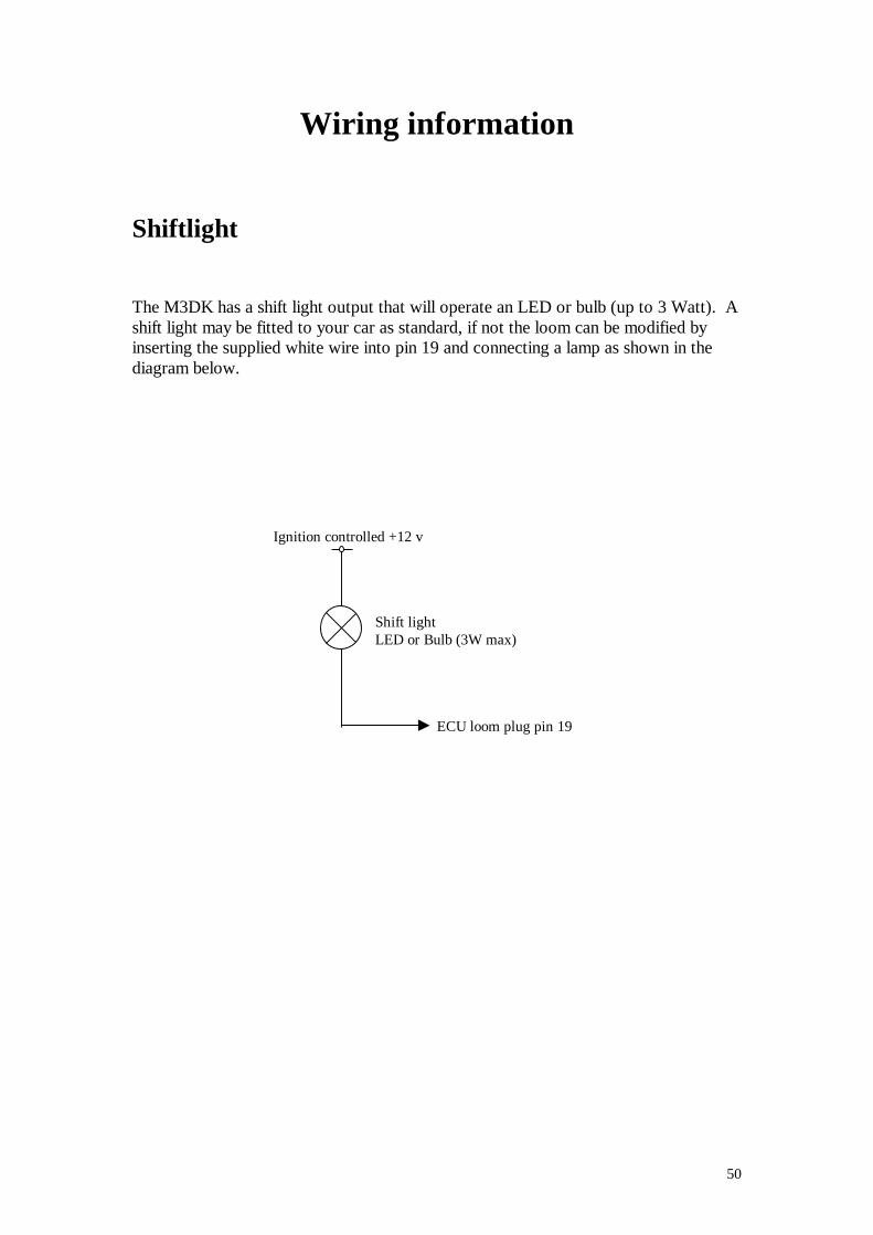
Shiftlight The M3DK has a shift light output that will operate an LED or bulb (up to 3 Watt). A shift light may be fitted to your car as standard, if not the loom can be modified by inserting the supplied white wire into pin 19 and connecting a lamp as shown in the diagram below.
ECU loom plug pin 19
Ignition controlled +12 v
Shift light LED or Bulb (3W max)
51
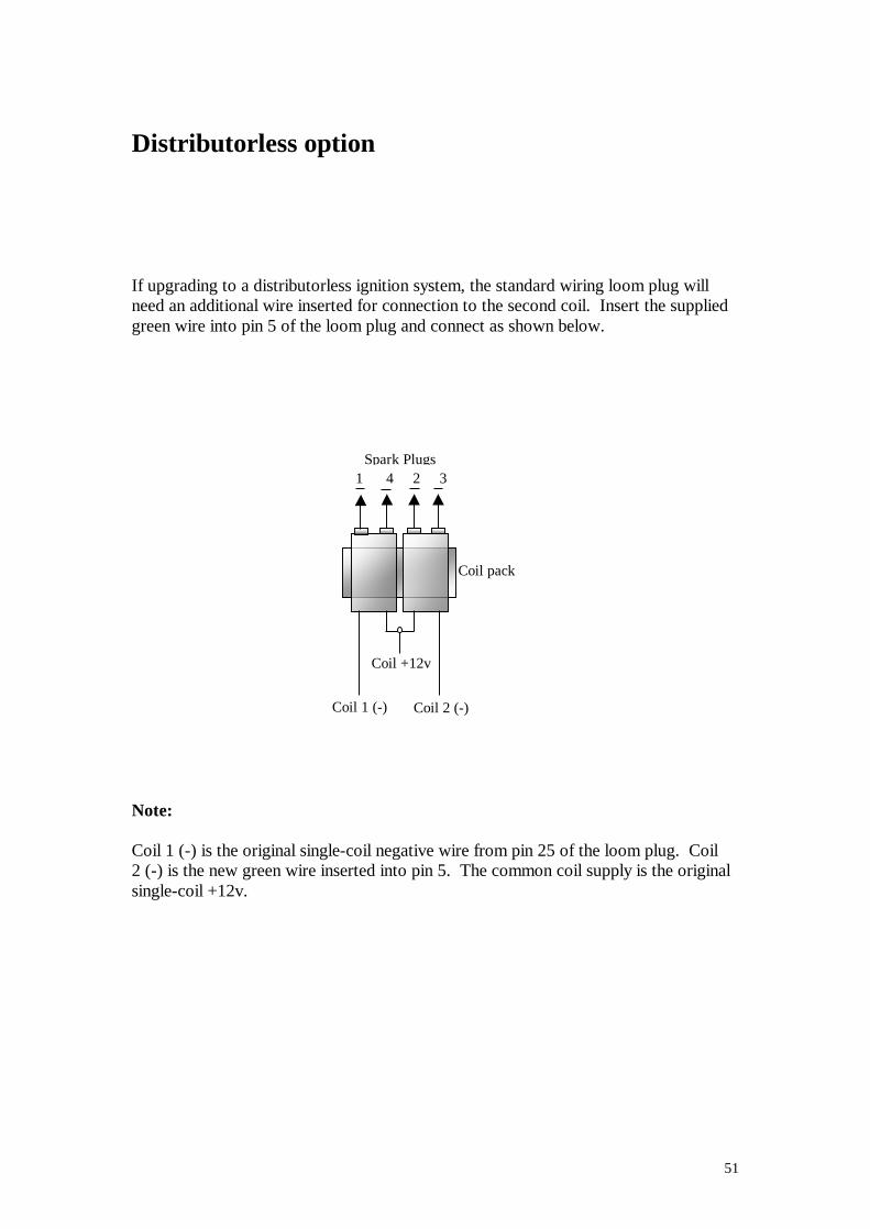
Distributorless option If upgrading to a distributorless ignition system, the standard wiring loom plug will need an additional wire inserted for connection to the second coil. Insert the supplied green wire into pin 5 of the loom plug and connect as shown below. Note: Coil 1 (-) is the original single-coil negative wire from pin 25 of the loom plug. Coil 2 (-) is the new green wire inserted into pin 5. The common coil supply is the original single-coil +12v.
Coil 2 (-) Coil 1 (-)
Coil +12v
Spark Plugs 1 4 2 3
Coil pack
52
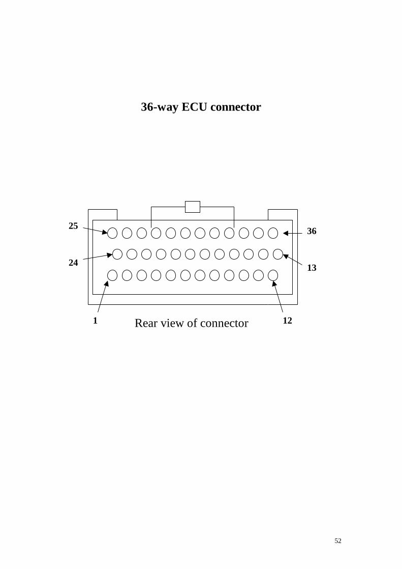
36-way ECU connector
24
25 36
1 12
13
Rear view of connector
53
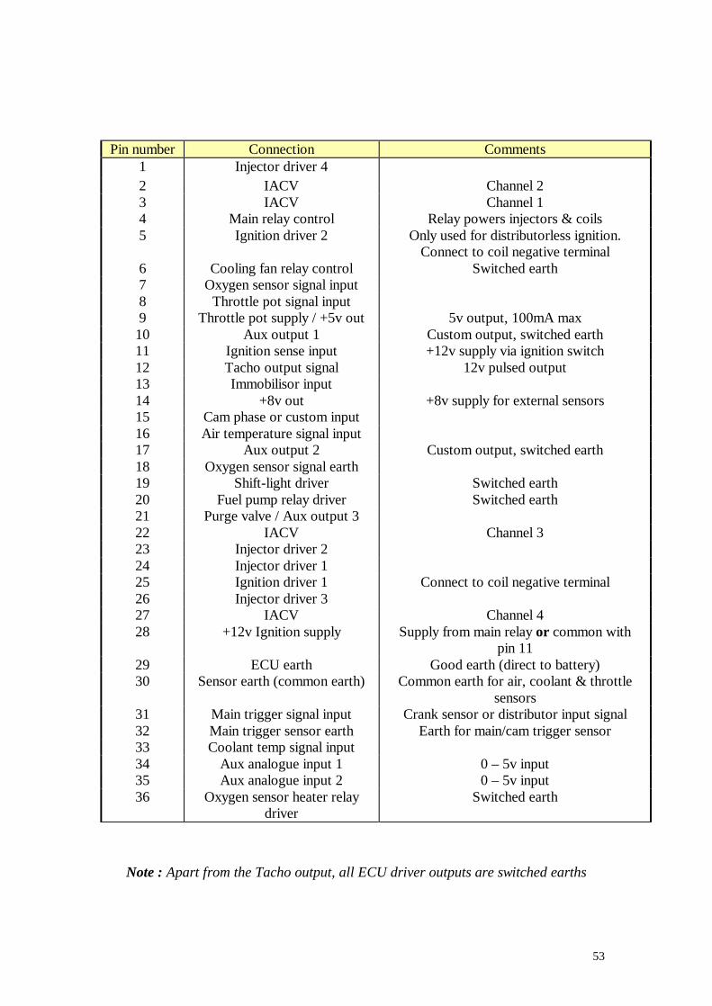
Pin number Connection Comments
1 Injector driver 4 2 IACV Channel 2 3 IACV Channel 1 4 Main relay control Relay powers injectors & coils 5 Ignition driver 2 Only used for distributorless ignition.
Connect to coil negative terminal 6 Cooling fan relay control Switched earth 7 Oxygen sensor signal input 8 Throttle pot signal input 9 Throttle pot supply / +5v out 5v output, 100mA max
10 Aux output 1 Custom output, switched earth 11 Ignition sense input +12v supply via ignition switch 12 Tacho output signal 12v pulsed output 13 Immobilisor input 14 +8v out +8v supply for external sensors 15 Cam phase or custom input 16 Air temperature signal input 17 Aux output 2 Custom output, switched earth 18 Oxygen sensor signal earth 19 Shift-light driver Switched earth 20 Fuel pump relay driver Switched earth 21 Purge valve / Aux output 3 22 IACV Channel 3 23 Injector driver 2 24 Injector driver 1 25 Ignition driver 1 Connect to coil negative terminal 26 Injector driver 3 27 IACV Channel 4 28 +12v Ignition supply Supply from main relay or common with
pin 11 29 ECU earth Good earth (direct to battery) 30 Sensor earth (common earth) Common earth for air, coolant & throttle
sensors 31 Main trigger signal input Crank sensor or distributor input signal 32 Main trigger sensor earth Earth for main/cam trigger sensor 33 Coolant temp signal input 34 Aux analogue input 1 0 – 5v input 35 Aux analogue input 2 0 – 5v input 36 Oxygen sensor heater relay
driver Switched earth
Note : Apart from the Tacho output, all ECU driver outputs are switched earths
54
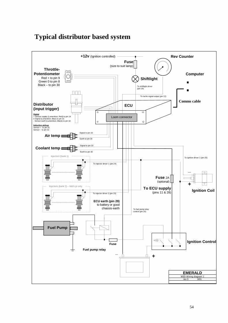
Typical distributor based system
To ignition driver 1 (pin 25)
Fuel pump relay
To injector driver 1 (pin 24)
Ignition Control
To fuel pump relay control (pin 20)
Fuse
Signal to pin 33
Earth to pin 30
Earth to pin 30
Signal to pin 16
Coolant temp
Air temp
To tacho signal output (pin 12)
To shiftlight driver (pin 19)
Ignition Coil
Throttle- Potentiometer
Red + to pin 9 Green 0 to pin 8 Black – to pin 30
Rev Counter
:
_
+
_ +
+12v (Ignition controlled)
Fuse (size to suit lamp)
Shiftlight
ECU
Comms cable
Computer
Distributor (input trigger) Digital + Sensor supply (Lumenition, Red) to pin 14 0 Signal (Lumenition, Blue) to pin 31 - Sensor earth (Lumenition, Black) to pin 32 Inductive pickup Sensor + to pin 31 Sensor – to pin 32
To ECU supply (pins 11 & 28)
ECU earth (pin 29) to battery or good
chassis-earth
Fuse 2A (optional)
EMERALD M3D Wiring diagram 1
rev 3 3/01
Fuel Pump
To injector driver 2 (pin 23)
Injectors (bank 1)
Injectors (bank 2) – 6&8 cyl only
Loom connector
55
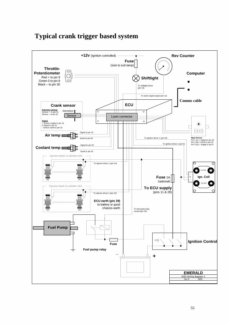
Typical crank trigger based system
Map Sensor Pin 1 (c) = Signal to pin 34 Pin 2 (b) = Earth to pin 30 Pin 3 (a) = Supply to pin 9 To ignition driver 2 (pin 5)
Cyl 2&3
Cyl 1&4
To ignition driver 1 (pin 25)
Signal to pin 16
Fuel pump relay
To injector driver 1 (pin 24)
Ignition Control
To fuel pump relay control (pin 20)
Fuse
Signal to pin 33
Earth to pin 30
Earth to pin 30
Coolant temp
Air temp
To tacho signal output (pin 12)
To shiftlight driver (pin 19)
Throttle- Potentiometer
Red + to pin 9 Green 0 to pin 8 Black – to pin 30
Rev Counter
:
_ +
+12v (Ignition controlled)
Fuse (size to suit lamp)
Shiftlight
ECU
Comms cable
Computer
Inductive pickup Sensor + to pin 31 Sensor – to pin 32 Digital + Sensor supply to pin 14 0 Signal to pin 31 - Sensor earth to pin 32
To ECU supply (pins 11 & 28)
ECU earth (pin 29) to battery or good
chassis-earth
Fuse 2A (optional)
EMERALD M3D Wiring diagram 2
rev 3 3/01
Fuel Pump
To injector driver 2 (pin 23)
Injectors (bank 1) cylinders 1&4
Injectors (bank 2) cylinders 2&3
Loom connector
Speed/pos
Sensor
Crank sensor
Ign. Coil - + -
56
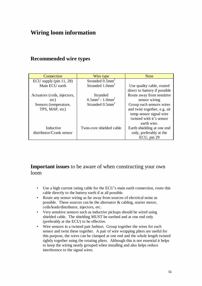
Wiring loom information
Recommended wire types
Connection Wire type Note ECU supply (pin 11, 28) Stranded 0.5mm2
Main ECU earth Stranded 1.0mm2 Use quality cable, routed direct to battery if possible
Actuators (coils, injectors, etc)
Stranded 0.5mm2 - 1.0mm2
Route away from sensitive sensor wiring
Sensors (temperature, TPS, MAP, etc)
Stranded 0.5mm2 Group each sensors wires and twist together, e.g. air
temp sensor signal wire twisted with it’s sensor
earth wire. Inductive
distributor/Crank sensor Twin-core shielded cable Earth shielding at one end
only, preferably at the ECU, pin 29
Important issues to be aware of when constructing your own loom
• Use a high current rating cable for the ECU’s main earth connection, route this cable directly to the battery earth if at all possible.
• Route any sensor wiring as far away from sources of electrical noise as possible. These sources can be the alternator & cabling, starter motor, coils/leads/distributor, injectors, etc.
• Very sensitive sensors such as inductive pickups should be wired using shielded cable. The shielding MUST be earthed and at one end only (preferably at the ECU) to be effective.
• Wire sensors in a twisted pair fashion. Group together the wires for each sensor and twist these together. A pair of wire wrapping pliers are useful for this purpose, the wires can be clamped at one end and the whole length twisted tightly together using the rotating pliers. Although this is not essential it helps to keep the wiring neatly grouped when installing and also helps reduce interference to the signal wires.
57
• Provide a good +12v supply to the ECU, coils, injectors, etc. Poor quality, high resistance connection or wiring to these components can reduce spark performance and cause noise from some components to affect the ECU.
• Support cable that has to run to the engine. The engine will move/vibrate, ensure that this movement will not stress the cable. If possible use an outer sheathing or plastic binding to remove the direct stress from the cable.
• Protect cables with sheathing/insulating material that have to run close by the exhaust manifolds.
• Limit the amount of soldered joints – a crimped connection can actually be more reliable. Solder can extend a little way, underneath the insulation, from a joint, this stiffens the cable at this point making it more prone to failure from fatigue. This is worth being aware of when making joints to cables that may be subjected to high vibration levels!
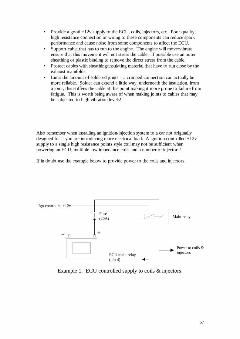
Also remember when installing an ignition/injection system to a car not originally designed for it you are introducing more electrical load. A ignition controlled +12v supply to a single high resistance points style coil may not be sufficient when powering an ECU, multiple low impedance coils and a number of injectors! If in doubt use the example below to provide power to the coils and injectors.
Example 1. ECU controlled supply to coils & injectors.
Fuse (20A)
ECU main relay (pin 4)
Ign controlled +12v
Power to coils & injectors
_ +
Main relay
58
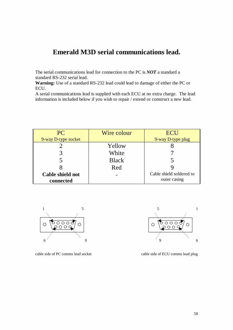
Emerald M3D serial communications lead. The serial communications lead for connection to the PC is NOT a standard a standard RS-232 serial lead. Warning: Use of a standard RS-232 lead could lead to damage of either the PC or ECU. A serial communications lead is supplied with each ECU at no extra charge. The lead information is included below if you wish to repair / extend or construct a new lead.
PC 9-way D-type socket
Wire colour ECU 9-way D-type plug
2 Yellow 8 3 White 7 5 Black 5 8 Red 9
Cable shield not connected
- Cable shield soldered to outer casing
1 5 5 1 6 9 9 6 cable side of PC comms lead socket cable side of ECU comms lead plug