Embed Size (px)
Citation preview
Canems Injection ECU www.canems.co.uk Release Version 2.17
___________________________________________________________________________
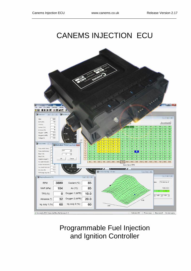
CANEMS INJECTION ECU
Programmable Fuel Injection and Ignition Controller
Canems Injection ECU www.canems.co.uk Release Version 2.17
___________________________________________________________________________
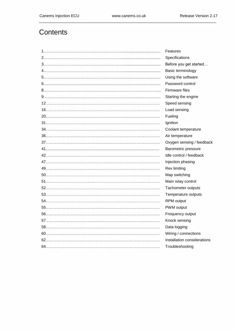
Contents
1……………………………………………………...................................
2……………………………………………………...................................
3……………………………………………………...................................
4……………………………………………………...................................
5……………………………………………………...................................
6...........................................................................................................
8……………………………………………………………………………...
9……………………………………………………...................................
12……………………………………………………………………………
16……………………………………………………………………………
20……………………………………………………………………………
31……………………………………………………………………………
34……………………………………………………………………………
36……………………………………………………………………………
37……………………………………………………………………………
41........................................................................................................
42……………………………………………………………………………
47……………………………………………………………………………
49……………………………………………………………………………
50……………………………………………………………………………
51……………………………………………………………………………
52……………………………………………………………………………
53……………………………………………………………………………
54……………………………………………………………………………
55……………………………………………………………………………
56……………………………………………………………………………
57……………………………………………………………………………
58……………………………………………………………………………
60……………………………………………………………………………
62……………………………………………………………………………
64……………………………………………………………………………
Features
Specifications
Before you get started…
Basic terminology
Using the software
Password control
Firmware files
Starting the engine
Speed sensing
Load sensing
Fueling
Ignition
Coolant temperature
Air temperature
Oxygen sensing / feedback
Barometric pressure
Idle control / feedback
Injection phasing
Rev limiting
Map switching
Main relay control
Tachometer outputs
Temperature outputs
RPM output
PWM output
Frequency output
Knock sensing
Data logging
Wiring / connections
Installation considerations
Troubleshooting
Canems Injection ECU www.canems.co.uk Release Version 2.17
___________________________________________________________________________
1
Features
• Fuel injection control for up to 8 cylinders
• Wasted spark ignition for up to 8 cylinders
• Distributor ignition for up to 8 cylinders
• Built-in coil ignitors (no need for external ignition amplifiers)
• Two 3D ignition timing maps with 252 programmable sites
• Two 3D fuel injection maps with 252 programmable sites
• Fuel / spark map switching at run time
• 12000+ RPM capability
• User programmable fuel cut, plus hard and soft rev limiting
• All settings real-time programmable
• Semi-sequential injection control (four cylinders)
• 3D injection advance map with 252 sites
• Support for one, two or three Bar MAP sensors
• MAP or TPS based load sensors
• Programmable speed and load sites
• Programmable transient enrichments & RPM correction
• Staged injector control
• Built-in main relay control
• Adjustable coil dwell control
• Voltage sensing with programmable dwell correction / injector opening time map
• Coolant temperature input with programmable correction map
• Air temperature input with programmable correction map
• Programmable cranking characteristics with temperature correction
• Two lambda sensor inputs for narrow band or wideband control
• Closed loop lambda control - programmable feedback rates / authority / enabling conditions
• Adjustable target air fuel ratio with wideband lambda feedback
• 3D target air fuel ratio map with 252 sites
• Closed loop idle control with programmable feedback rates / authority / enabling conditions
• PWM valve and / or spark scatter idle control
• Programmable fuel compensation map for idle valve
• Temperature controlled outputs with programmable on / off temperatures
• Programmable RPM-based output (VTEC etc.)
• 3D PWM output with 252 programmable sites (turbo boost control etc.)
• Interpolation on all maps
• Inbuilt diagnostics LED
• Diagnostic recording of min / max inputs and outputs
• Data logging of up to 24 optional parameters
• Adjustable recording rate for data logger
• RPM input from either VR or Hall effect sensors with 36-1, 60-2, Renix 44-2, Mazda MX5 NA & NB, Rover K Series 36-2 & 36-4, GM 24x, Hayabusa/GSXR 24-2 trigger patterns
• Barometric pressure sampling & correction
• Atmospheric correction to ignition timing
• Password control & partial access control
• Optional closed-loop knock control
• Optional internal data logging memory
• Third party digi dash output support via RS232
• Tuning software, PC connection cable and loom plug/pins included
Canems Injection ECU www.canems.co.uk Release Version 2.17
___________________________________________________________________________
2
Specification
• Weight 468 grams
• Dimensions 140mm x 153mm x 54mm
• Rugged ABS casing with ceramic heat sinks
• Waterproof to IP67 specification (one metre)
• Negative earth power supply, 7 – 18V
• ECU current consumption < 0.5A
• Ignition coil current - maximum 10A
• Fuel injector output - maximum 10A
• Idle valve / PWM output - maximum 5A
• Programmable outputs - maximum 1A
• 30-way high current, waterproof connector
• RS232 serial port interface with optional USB support
Canems Injection ECU www.canems.co.uk Release Version 2.17
___________________________________________________________________________
3
Before you get started…
The Canems Injection ECU has four high current injection outputs and four high current ignition outputs. Each output can hold a constant current of 10 Amps maximum. Ignition coils should have a primary resistance of greater than 0.6 Ohms. Low impedance injectors (with a resistance of less than 6 Ohms) should always be wired in series with current-limiting ballast resistors.
Support is available from Canems in sourcing components, installing the engine management system and programming the ECU to suit your requirements. The ECU is designed to operate in conjunction with easily obtainable components. It is our policy to design systems that require no unique hardware, and will always endeavour to have spares available in the future.
The Canems Injection Tuner software displays all lambda sensor inputs as air fuel ratios (AFRs). It should be noted that only wideband lambda sensors are capable of giving a true reading over a wide range of AFRs. Narrow-band sensors can only indicate an over-lean (or over-rich) mixture, though the ECU, tuning software and data logs will of course reflect this behaviour.
Rolling road time is expensive, so our software is designed to be quick and easy to use; even for people with little experience. All fuel and ignition maps can be accessed with keyboard shortcuts, and you can change values with one touch of the keyboard. There is no need to waste valuable time when typing individual values and you can even tune your 3D maps visually, with the aid of graphical representations.
Our ECUs are designed to give total reliability and total control over engine parameters. However, full responsibility for the engine and vehicle in question remains solely with the owner. Canems can in no way be held responsible for damage or injury caused by incorrect fitting procedures, failure in use or neglect of appropriate safety measures.
Canems Injection ECU www.canems.co.uk Release Version 2.17
___________________________________________________________________________
4
Basic terminology
Pulse width
Pulse width is a measurement of time. Typically used to describe the amount of time for which a fuel injector is held open. The longer an injector is held open for, the more fuel is able to flow into the engine. Therefore, there is a direct relationship between fuel mixture and injector pulse width. Due to the fast switching nature of fuel injectors, pulse width will typically be measured in milliseconds (thousandths of a second).
Duty cycle
Duty cycle describes the amount of time for which an output is held ‘on’. It is measured as a percentage. For example, an injector held open for 8 milliseconds, then closed for 2 milliseconds, has a duty cycle of 80%. As RPM increases, fuel injectors have an increasingly short space of time in which to inject the required fuel. It doesn’t help that the engine will probably want more fuel at high speed either. If the duty cycle exceeds 100%, this means the injector is open full-time. It has reached the limit of its flow capabilities and is no longer able to supply more fuel.
PWM
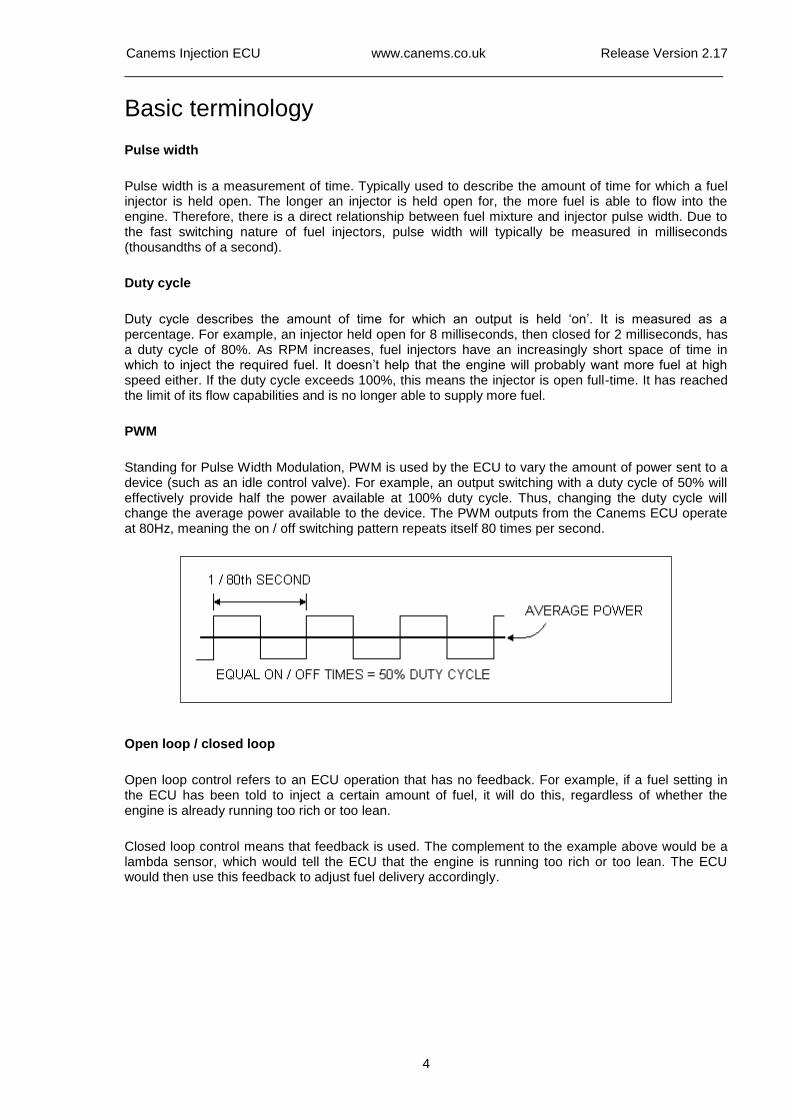
Standing for Pulse Width Modulation, PWM is used by the ECU to vary the amount of power sent to a device (such as an idle control valve). For example, an output switching with a duty cycle of 50% will effectively provide half the power available at 100% duty cycle. Thus, changing the duty cycle will change the average power available to the device. The PWM outputs from the Canems ECU operate at 80Hz, meaning the on / off switching pattern repeats itself 80 times per second.
Open loop / closed loop
Open loop control refers to an ECU operation that has no feedback. For example, if a fuel setting in the ECU has been told to inject a certain amount of fuel, it will do this, regardless of whether the engine is already running too rich or too lean.
Closed loop control means that feedback is used. The complement to the example above would be a lambda sensor, which would tell the ECU that the engine is running too rich or too lean. The ECU would then use this feedback to adjust fuel delivery accordingly.
Canems Injection ECU www.canems.co.uk Release Version 2.17
___________________________________________________________________________
5
Using the software
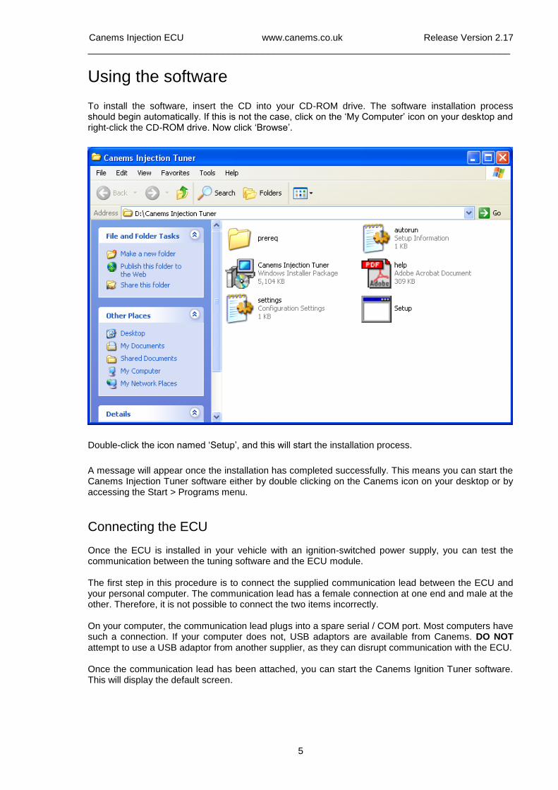
To install the software, insert the CD into your CD-ROM drive. The software installation process should begin automatically. If this is not the case, click on the ‘My Computer’ icon on your desktop and right-click the CD-ROM drive. Now click ‘Browse’.
Double-click the icon named ‘Setup’, and this will start the installation process.
A message will appear once the installation has completed successfully. This means you can start the Canems Injection Tuner software either by double clicking on the Canems icon on your desktop or by accessing the Start > Programs menu.
Connecting the ECU Once the ECU is installed in your vehicle with an ignition-switched power supply, you can test the communication between the tuning software and the ECU module. The first step in this procedure is to connect the supplied communication lead between the ECU and your personal computer. The communication lead has a female connection at one end and male at the other. Therefore, it is not possible to connect the two items incorrectly. On your computer, the communication lead plugs into a spare serial / COM port. Most computers have such a connection. If your computer does not, USB adaptors are available from Canems. DO NOT attempt to use a USB adaptor from another supplier, as they can disrupt communication with the ECU. Once the communication lead has been attached, you can start the Canems Ignition Tuner software. This will display the default screen.
Canems Injection ECU www.canems.co.uk Release Version 2.17
___________________________________________________________________________
6
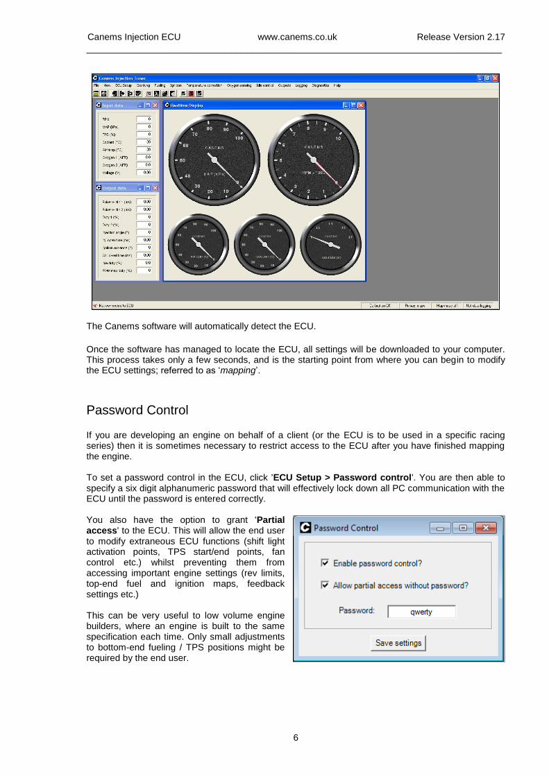
The Canems software will automatically detect the ECU.
Once the software has managed to locate the ECU, all settings will be downloaded to your computer. This process takes only a few seconds, and is the starting point from where you can begin to modify the ECU settings; referred to as ‘mapping’.
Password Control
If you are developing an engine on behalf of a client (or the ECU is to be used in a specific racing series) then it is sometimes necessary to restrict access to the ECU after you have finished mapping the engine. To set a password control in the ECU, click 'ECU Setup > Password control'. You are then able to specify a six digit alphanumeric password that will effectively lock down all PC communication with the ECU until the password is entered correctly. You also have the option to grant 'Partial access' to the ECU. This will allow the end user to modify extraneous ECU functions (shift light activation points, TPS start/end points, fan control etc.) whilst preventing them from accessing important engine settings (rev limits, top-end fuel and ignition maps, feedback settings etc.) This can be very useful to low volume engine builders, where an engine is built to the same specification each time. Only small adjustments to bottom-end fueling / TPS positions might be required by the end user.
Canems Injection ECU www.canems.co.uk Release Version 2.17
___________________________________________________________________________
7
Inputs, outputs and real-time data
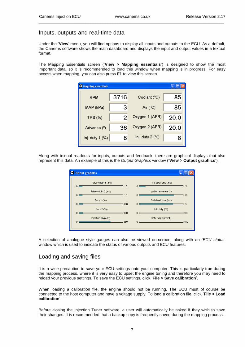
Under the ‘View’ menu, you will find options to display all inputs and outputs to the ECU. As a default, the Canems software shows the main dashboard and displays the input and output values in a textual format.
The Mapping Essentials screen (‘View > Mapping essentials’) is designed to show the most important data, so it is recommended to load this window when mapping is in progress. For easy access when mapping, you can also press F1 to view this screen.
Along with textual readouts for inputs, outputs and feedback, there are graphical displays that also represent this data. An example of this is the Output Graphics window (‘View > Output graphics’).
A selection of analogue style gauges can also be viewed on-screen, along with an ‘ECU status’ window which is used to indicate the status of various outputs and ECU features.
Loading and saving files
It is a wise precaution to save your ECU settings onto your computer. This is particularly true during the mapping process, where it is very easy to upset the engine tuning and therefore you may need to reload your previous settings. To save the ECU settings, click ‘File > Save calibration’.
When loading a calibration file, the engine should not be running. The ECU must of course be connected to the host computer and have a voltage supply. To load a calibration file, click ‘File > Load calibration’.
Before closing the Injection Tuner software, a user will automatically be asked if they wish to save their changes. It is recommended that a backup copy is frequently saved during the mapping process.
Canems Injection ECU www.canems.co.uk Release Version 2.17
___________________________________________________________________________
8
Firmware Files
When major changes need to be made to your ECU, you’ll need to change the software inside the ECU itself. Examples would be changing the number of cylinders that the ECU controls or swapping from a 36-1 to a 60-2 trigger wheel.
To get the latest firmware files, visit the Canems website. From here, upgrades for your ECU can be downloaded free of charge. Firmware files are also distributed with your installation CD though naturally they may not be the most recent.
Uploading firmware files
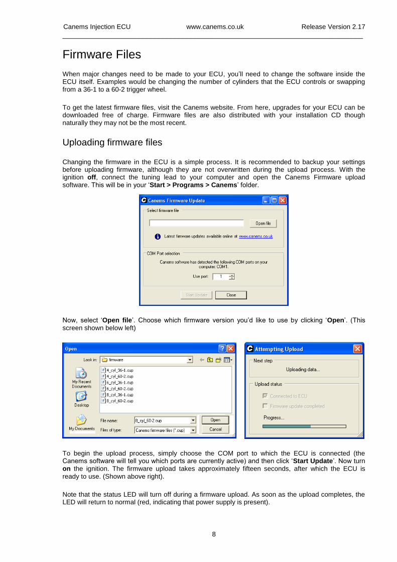
Changing the firmware in the ECU is a simple process. It is recommended to backup your settings before uploading firmware, although they are not overwritten during the upload process. With the ignition off, connect the tuning lead to your computer and open the Canems Firmware upload software. This will be in your ‘Start > Programs > Canems’ folder.
Now, select ‘Open file’. Choose which firmware version you’d like to use by clicking ‘Open’. (This screen shown below left)
To begin the upload process, simply choose the COM port to which the ECU is connected (the Canems software will tell you which ports are currently active) and then click ‘Start Update’. Now turn on the ignition. The firmware upload takes approximately fifteen seconds, after which the ECU is ready to use. (Shown above right).
Note that the status LED will turn off during a firmware upload. As soon as the upload completes, the LED will return to normal (red, indicating that power supply is present).
Canems Injection ECU www.canems.co.uk Release Version 2.17
___________________________________________________________________________
9
Starting the engine
Before attempting to start the engine, make sure you have read and understood all necessary sections of this installation guide. Remember that the basic engine design remains unchanged, even after fitting aftermarket management. Given the correct mixture of fuel and air, the engine will run.
Calibrating the TPS
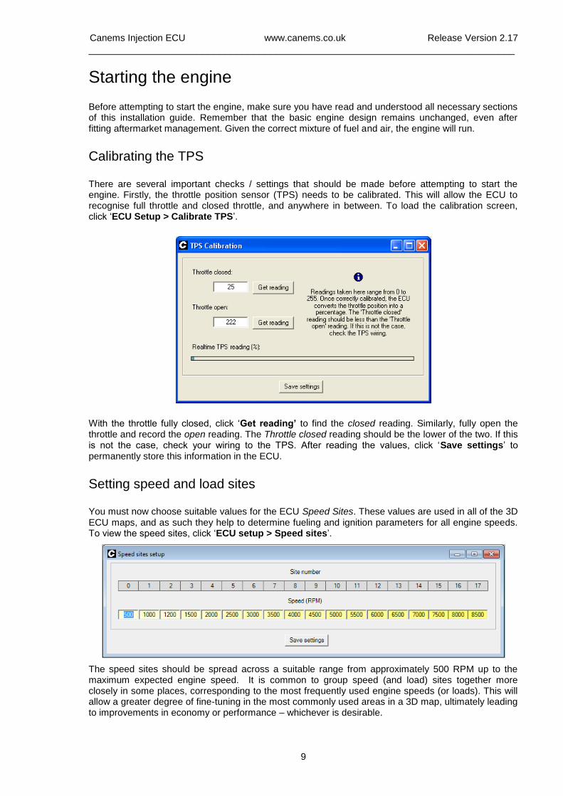
There are several important checks / settings that should be made before attempting to start the engine. Firstly, the throttle position sensor (TPS) needs to be calibrated. This will allow the ECU to recognise full throttle and closed throttle, and anywhere in between. To load the calibration screen, click ‘ECU Setup > Calibrate TPS’.
With the throttle fully closed, click ‘Get reading’ to find the closed reading. Similarly, fully open the throttle and record the open reading. The Throttle closed reading should be the lower of the two. If this is not the case, check your wiring to the TPS. After reading the values, click ‘Save settings’ to permanently store this information in the ECU.
Setting speed and load sites
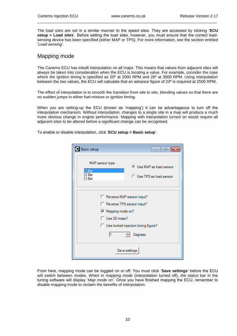
You must now choose suitable values for the ECU Speed Sites. These values are used in all of the 3D ECU maps, and as such they help to determine fueling and ignition parameters for all engine speeds. To view the speed sites, click ‘ECU setup > Speed sites’.
The speed sites should be spread across a suitable range from approximately 500 RPM up to the maximum expected engine speed. It is common to group speed (and load) sites together more closely in some places, corresponding to the most frequently used engine speeds (or loads). This will allow a greater degree of fine-tuning in the most commonly used areas in a 3D map, ultimately leading to improvements in economy or performance – whichever is desirable.
Canems Injection ECU www.canems.co.uk Release Version 2.17
___________________________________________________________________________
10
The load sites are set in a similar manner to the speed sites. They are accessed by clicking ‘ECU setup > Load sites’. Before setting the load sites, however, you must ensure that the correct load-sensing device has been specified (either MAP or TPS). For more information, see the section entitled ‘Load sensing’.
Mapping mode
The Canems ECU has inbuilt interpolation on all maps. This means that values from adjacent sites will always be taken into consideration when the ECU is locating a value. For example, consider the case where the ignition timing is specified as 20º at 2000 RPM and 26º at 3000 RPM. Using interpolation between the two values, the ECU will calculate that an advance figure of 23º is required at 2500 RPM.
The effect of interpolation is to smooth the transition from site to site, blending values so that there are no sudden jumps in either fuel mixture or ignition timing.
When you are setting-up the ECU (known as ‘mapping’) it can be advantageous to turn off the interpolation mechanism. Without interpolation, changes to a single site in a map will produce a much more obvious change in engine performance. Mapping with interpolation turned on would require all adjacent sites to be altered before a significant change can be recognised.
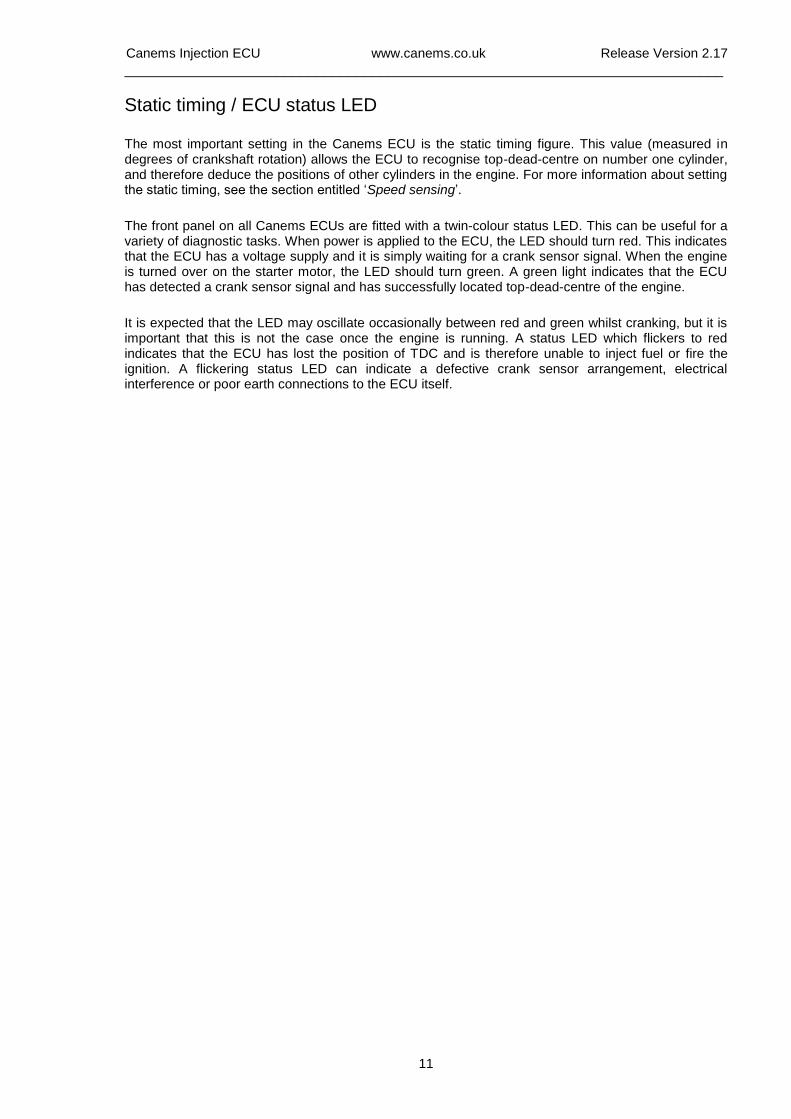
To enable or disable interpolation, click ‘ECU setup > Basic setup’.
From here, mapping mode can be toggled on or off. You must click ‘Save settings’ before the ECU will switch between modes. When in mapping mode (interpolation turned off), the status bar in the tuning software will display ‘Map mode on’. Once you have finished mapping the ECU, remember to disable mapping mode to reclaim the benefits of interpolation.
Canems Injection ECU www.canems.co.uk Release Version 2.17
___________________________________________________________________________
11
Static timing / ECU status LED
The most important setting in the Canems ECU is the static timing figure. This value (measured in degrees of crankshaft rotation) allows the ECU to recognise top-dead-centre on number one cylinder, and therefore deduce the positions of other cylinders in the engine. For more information about setting the static timing, see the section entitled ‘Speed sensing’.
The front panel on all Canems ECUs are fitted with a twin-colour status LED. This can be useful for a variety of diagnostic tasks. When power is applied to the ECU, the LED should turn red. This indicates that the ECU has a voltage supply and it is simply waiting for a crank sensor signal. When the engine is turned over on the starter motor, the LED should turn green. A green light indicates that the ECU has detected a crank sensor signal and has successfully located top-dead-centre of the engine.
It is expected that the LED may oscillate occasionally between red and green whilst cranking, but it is important that this is not the case once the engine is running. A status LED which flickers to red indicates that the ECU has lost the position of TDC and is therefore unable to inject fuel or fire the ignition. A flickering status LED can indicate a defective crank sensor arrangement, electrical interference or poor earth connections to the ECU itself.
Canems Injection ECU www.canems.co.uk Release Version 2.17
___________________________________________________________________________
12
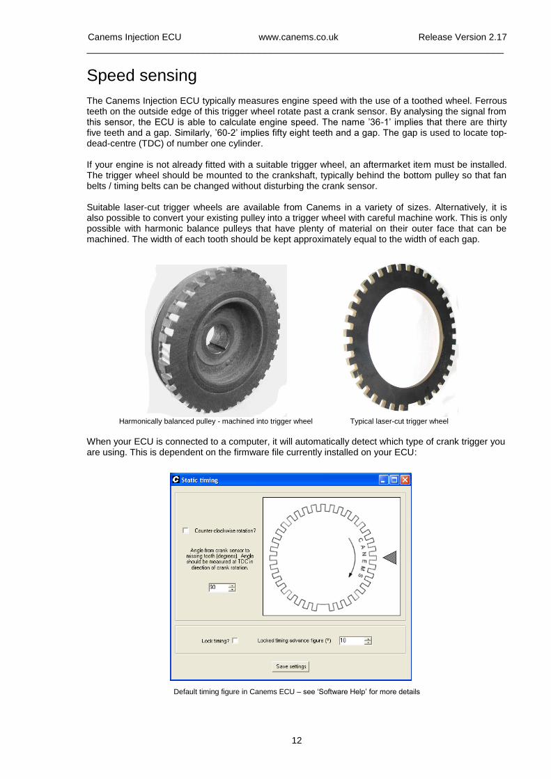
Speed sensing The Canems Injection ECU typically measures engine speed with the use of a toothed wheel. Ferrous teeth on the outside edge of this trigger wheel rotate past a crank sensor. By analysing the signal from this sensor, the ECU is able to calculate engine speed. The name ’36-1’ implies that there are thirty five teeth and a gap. Similarly, ’60-2’ implies fifty eight teeth and a gap. The gap is used to locate top-dead-centre (TDC) of number one cylinder. If your engine is not already fitted with a suitable trigger wheel, an aftermarket item must be installed. The trigger wheel should be mounted to the crankshaft, typically behind the bottom pulley so that fan belts / timing belts can be changed without disturbing the crank sensor. Suitable laser-cut trigger wheels are available from Canems in a variety of sizes. Alternatively, it is also possible to convert your existing pulley into a trigger wheel with careful machine work. This is only possible with harmonic balance pulleys that have plenty of material on their outer face that can be machined. The width of each tooth should be kept approximately equal to the width of each gap.
Harmonically balanced pulley - machined into trigger wheel
Typical laser-cut trigger wheel
When your ECU is connected to a computer, it will automatically detect which type of crank trigger you are using. This is dependent on the firmware file currently installed on your ECU:
Default timing figure in Canems ECU – see ‘Software Help’ for more details
Canems Injection ECU www.canems.co.uk Release Version 2.17
___________________________________________________________________________
13
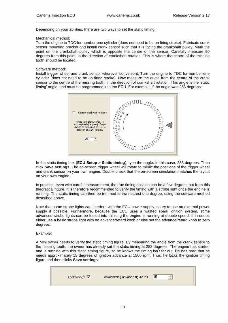
Depending on your abilities, there are two ways to set the static timing: Mechanical method: Turn the engine to TDC for number one cylinder (does not need to be on firing stroke). Fabricate crank sensor mounting bracket and install crank sensor such that it is facing the crankshaft pulley. Mark the point on the crankshaft pulley which is opposite the centre of the sensor. Carefully measure 90 degrees from this point, in the direction of crankshaft rotation. This is where the centre of the missing tooth should be located. Software method: Install trigger wheel and crank sensor wherever convenient. Turn the engine to TDC for number one cylinder (does not need to be on firing stroke). Now measure the angle from the centre of the crank sensor to the centre of the missing tooth, in the direction of crankshaft rotation. This angle is the ‘static timing’ angle, and must be programmed into the ECU. For example, if the angle was 283 degrees:
In the static timing box (ECU Setup > Static timing), type the angle. In this case, 283 degrees. Then click Save settings. The on-screen trigger wheel will rotate to mimic the positions of the trigger wheel and crank sensor on your own engine. Double check that the on-screen simulation matches the layout on your own engine. In practice, even with careful measurement, the true timing position can be a few degrees out from this theoretical figure. It is therefore recommended to verify the timing with a strobe light once the engine is running. The static timing can then be trimmed to the nearest one degree, using the software method described above. Note that some strobe lights can interfere with the ECU power supply, so try to use an external power supply if possible. Furthermore, because the ECU uses a wasted spark ignition system, some advanced strobe lights can be fooled into thinking the engine is running at double speed. If in doubt, either use a basic strobe light with no advance/retard knob or else set the advance/retard knob to zero degrees. Example: A Mini owner needs to verify the static timing figure. By measuring the angle from the crank sensor to the missing tooth, the owner has already set the static timing at 283 degrees. The engine has started and is running with this static timing figure, so he knows the timing isn’t far out. He has read that he needs approximately 15 degrees of ignition advance at 1500 rpm. Thus, he locks the ignition timing figure and then clicks Save settings:
Canems Injection ECU www.canems.co.uk Release Version 2.17
___________________________________________________________________________
14
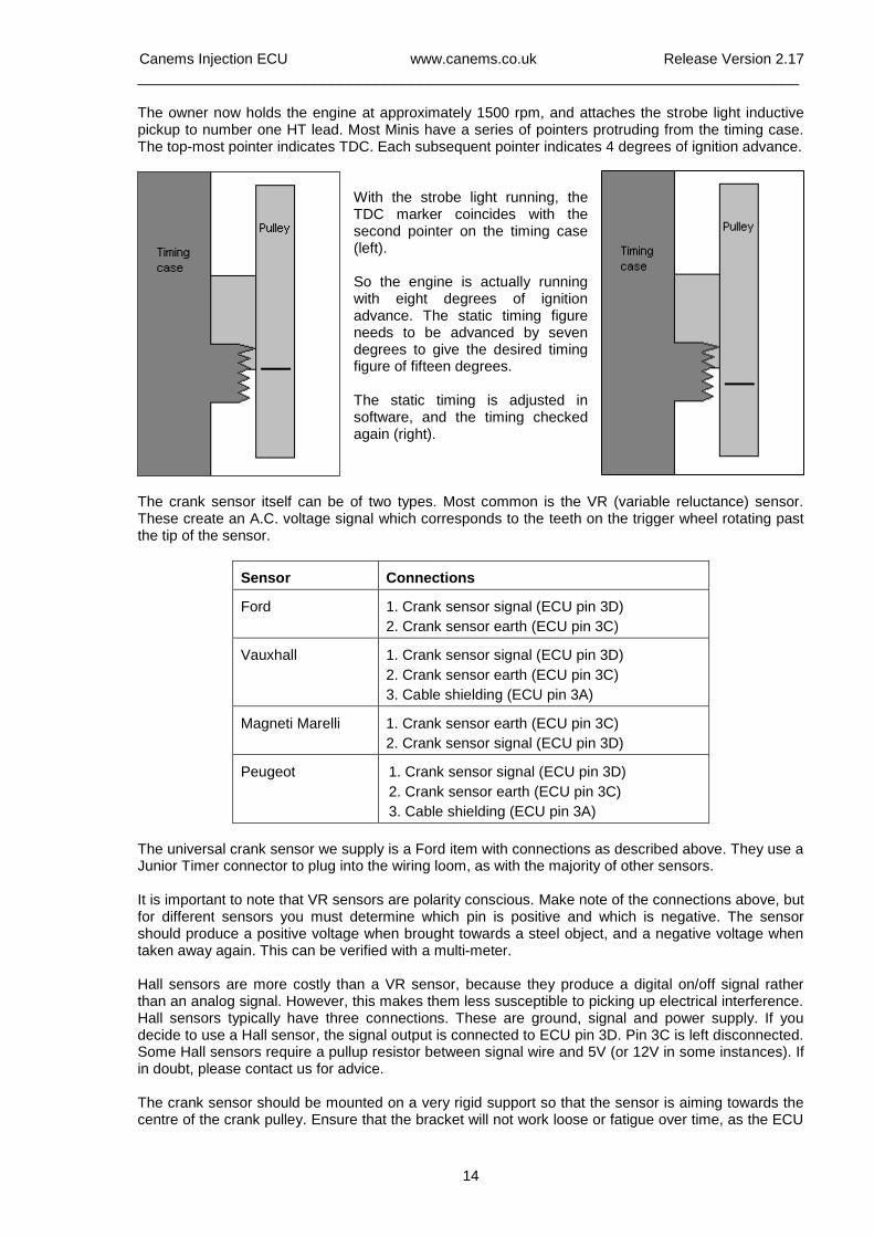
The owner now holds the engine at approximately 1500 rpm, and attaches the strobe light inductive pickup to number one HT lead. Most Minis have a series of pointers protruding from the timing case. The top-most pointer indicates TDC. Each subsequent pointer indicates 4 degrees of ignition advance.
With the strobe light running, the TDC marker coincides with the second pointer on the timing case (left). So the engine is actually running with eight degrees of ignition advance. The static timing figure needs to be advanced by seven degrees to give the desired timing figure of fifteen degrees. The static timing is adjusted in software, and the timing checked again (right).
The crank sensor itself can be of two types. Most common is the VR (variable reluctance) sensor. These create an A.C. voltage signal which corresponds to the teeth on the trigger wheel rotating past the tip of the sensor.
Sensor
Connections
Ford
1. Crank sensor signal (ECU pin 3D)
2. Crank sensor earth (ECU pin 3C)
Vauxhall
1. Crank sensor signal (ECU pin 3D)
2. Crank sensor earth (ECU pin 3C)
3. Cable shielding (ECU pin 3A)
Magneti Marelli
1. Crank sensor earth (ECU pin 3C)
2. Crank sensor signal (ECU pin 3D)
Peugeot
1. Crank sensor signal (ECU pin 3D)
2. Crank sensor earth (ECU pin 3C)
3. Cable shielding (ECU pin 3A)
The universal crank sensor we supply is a Ford item with connections as described above. They use a Junior Timer connector to plug into the wiring loom, as with the majority of other sensors. It is important to note that VR sensors are polarity conscious. Make note of the connections above, but for different sensors you must determine which pin is positive and which is negative. The sensor should produce a positive voltage when brought towards a steel object, and a negative voltage when taken away again. This can be verified with a multi-meter. Hall sensors are more costly than a VR sensor, because they produce a digital on/off signal rather than an analog signal. However, this makes them less susceptible to picking up electrical interference. Hall sensors typically have three connections. These are ground, signal and power supply. If you decide to use a Hall sensor, the signal output is connected to ECU pin 3D. Pin 3C is left disconnected. Some Hall sensors require a pullup resistor between signal wire and 5V (or 12V in some instances). If in doubt, please contact us for advice. The crank sensor should be mounted on a very rigid support so that the sensor is aiming towards the centre of the crank pulley. Ensure that the bracket will not work loose or fatigue over time, as the ECU
Canems Injection ECU www.canems.co.uk Release Version 2.17
___________________________________________________________________________
15
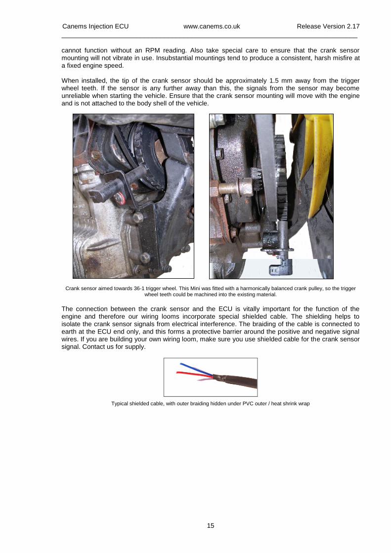
cannot function without an RPM reading. Also take special care to ensure that the crank sensor mounting will not vibrate in use. Insubstantial mountings tend to produce a consistent, harsh misfire at a fixed engine speed. When installed, the tip of the crank sensor should be approximately 1.5 mm away from the trigger wheel teeth. If the sensor is any further away than this, the signals from the sensor may become unreliable when starting the vehicle. Ensure that the crank sensor mounting will move with the engine and is not attached to the body shell of the vehicle.
Crank sensor aimed towards 36-1 trigger wheel. This Mini was fitted with a harmonically balanced crank pulley, so the trigger
wheel teeth could be machined into the existing material.
The connection between the crank sensor and the ECU is vitally important for the function of the engine and therefore our wiring looms incorporate special shielded cable. The shielding helps to isolate the crank sensor signals from electrical interference. The braiding of the cable is connected to earth at the ECU end only, and this forms a protective barrier around the positive and negative signal wires. If you are building your own wiring loom, make sure you use shielded cable for the crank sensor signal. Contact us for supply.
Typical shielded cable, with outer braiding hidden under PVC outer / heat shrink wrap
Canems Injection ECU www.canems.co.uk Release Version 2.17
___________________________________________________________________________
16
Load sensing Most of the main maps in the Canems ECU are 3D. This means each map has a speed-referenced axis and a load-referenced axis. The speed axis is based on how quickly the engine is turning, while the load axis is based on how hard the engine is working. For example, an engine pulling top gear up a hill is working much harder than an engine coasting downhill in second gear. This is where the load sensor comes in – it can differentiate between the two conditions. On standard or mildly tuned engines, it’s recommended to use a MAP (Manifold Absolute Pressure) sensor to detect load. These devices connect to the inlet manifold via vacuum piping and report the current manifold pressure to the ECU. The Canems ECU can use one, two or three Bar MAP sensors so it is capable of controlling forced induction applications. For normally aspirated applications with upgraded camshafts and/or individual throttle bodies, it is also possible to use a throttle position sensor (TPS) to measure engine load. This avoids the problem of a fluctuating vacuum signal which a MAP sensor would find hard to measure accurately. TPS devices do not measure true engine load, but base their load prediction around the current throttle position. For race applications, this solution can be advantageous.
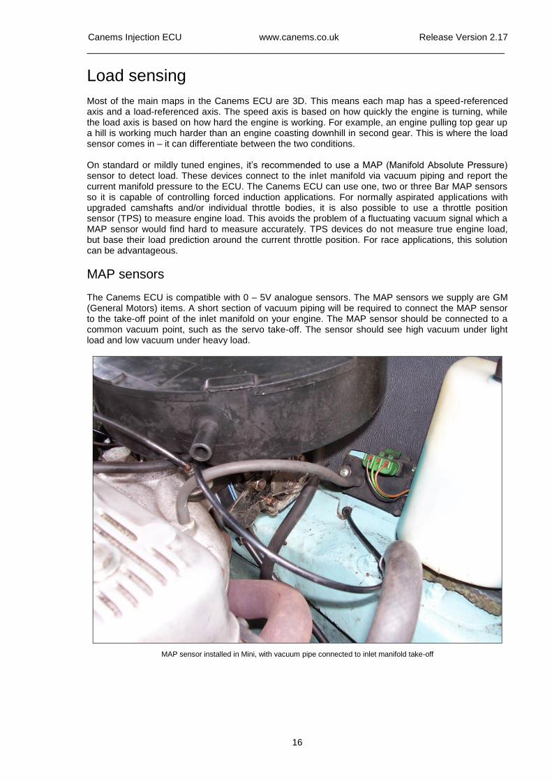
MAP sensors The Canems ECU is compatible with 0 – 5V analogue sensors. The MAP sensors we supply are GM (General Motors) items. A short section of vacuum piping will be required to connect the MAP sensor to the take-off point of the inlet manifold on your engine. The MAP sensor should be connected to a common vacuum point, such as the servo take-off. The sensor should see high vacuum under light load and low vacuum under heavy load.
MAP sensor installed in Mini, with vacuum pipe connected to inlet manifold take-off
Canems Injection ECU www.canems.co.uk Release Version 2.17
___________________________________________________________________________
17
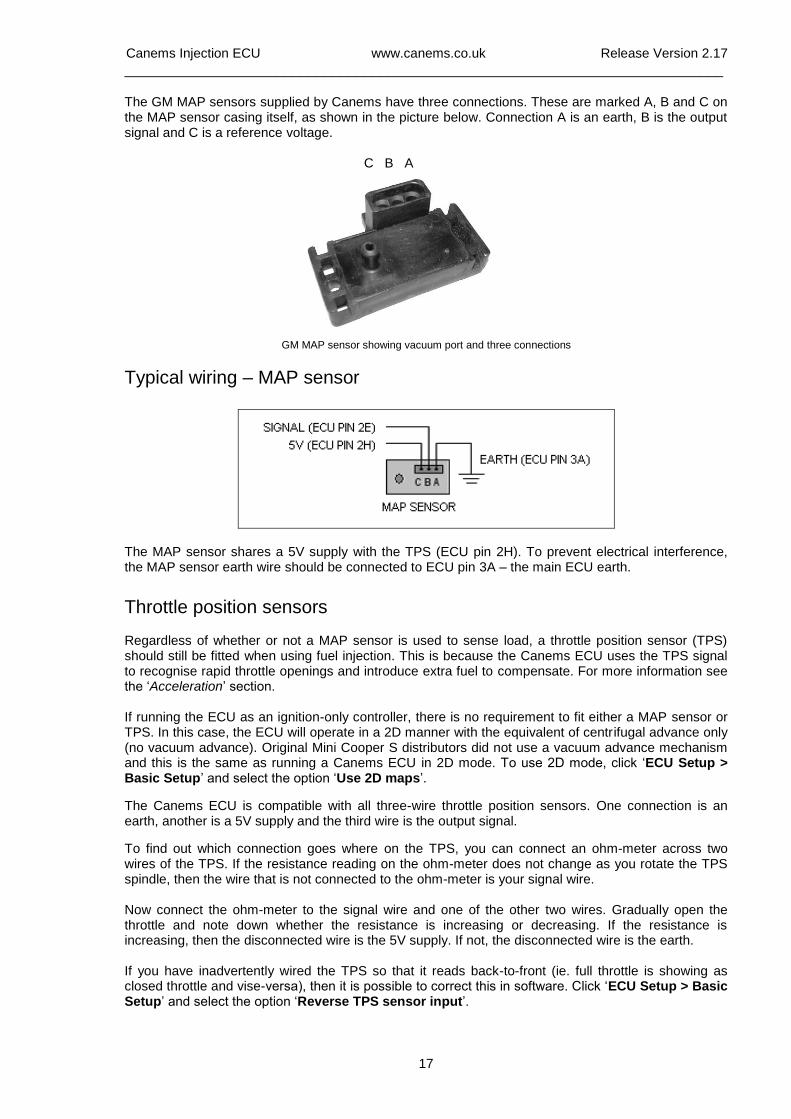
The GM MAP sensors supplied by Canems have three connections. These are marked A, B and C on the MAP sensor casing itself, as shown in the picture below. Connection A is an earth, B is the output signal and C is a reference voltage.
C B A
GM MAP sensor showing vacuum port and three connections
Typical wiring – MAP sensor
The MAP sensor shares a 5V supply with the TPS (ECU pin 2H). To prevent electrical interference, the MAP sensor earth wire should be connected to ECU pin 3A – the main ECU earth.
Throttle position sensors Regardless of whether or not a MAP sensor is used to sense load, a throttle position sensor (TPS) should still be fitted when using fuel injection. This is because the Canems ECU uses the TPS signal to recognise rapid throttle openings and introduce extra fuel to compensate. For more information see the ‘Acceleration’ section. If running the ECU as an ignition-only controller, there is no requirement to fit either a MAP sensor or TPS. In this case, the ECU will operate in a 2D manner with the equivalent of centrifugal advance only (no vacuum advance). Original Mini Cooper S distributors did not use a vacuum advance mechanism and this is the same as running a Canems ECU in 2D mode. To use 2D mode, click ‘ECU Setup > Basic Setup’ and select the option ‘Use 2D maps’.
The Canems ECU is compatible with all three-wire throttle position sensors. One connection is an earth, another is a 5V supply and the third wire is the output signal.
To find out which connection goes where on the TPS, you can connect an ohm-meter across two wires of the TPS. If the resistance reading on the ohm-meter does not change as you rotate the TPS spindle, then the wire that is not connected to the ohm-meter is your signal wire. Now connect the ohm-meter to the signal wire and one of the other two wires. Gradually open the throttle and note down whether the resistance is increasing or decreasing. If the resistance is increasing, then the disconnected wire is the 5V supply. If not, the disconnected wire is the earth. If you have inadvertently wired the TPS so that it reads back-to-front (ie. full throttle is showing as closed throttle and vise-versa), then it is possible to correct this in software. Click ‘ECU Setup > Basic Setup’ and select the option ‘Reverse TPS sensor input’.
Canems Injection ECU www.canems.co.uk Release Version 2.17
___________________________________________________________________________
18
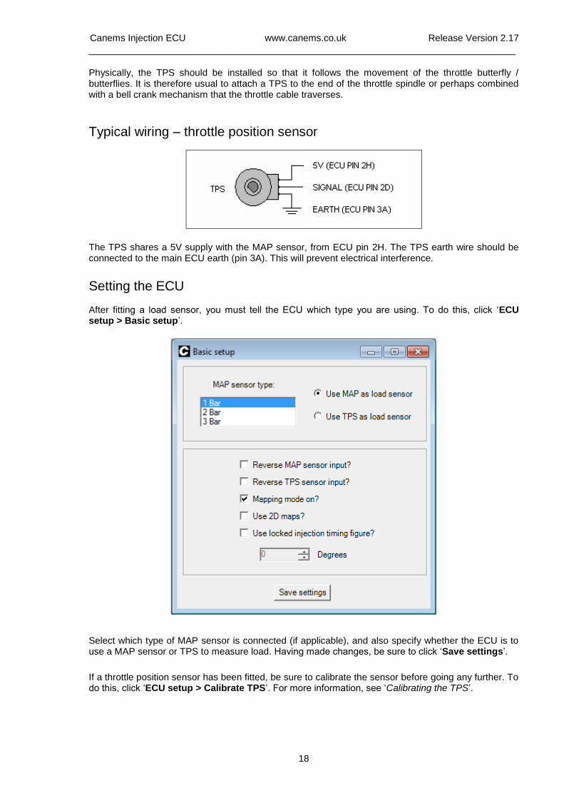
Physically, the TPS should be installed so that it follows the movement of the throttle butterfly / butterflies. It is therefore usual to attach a TPS to the end of the throttle spindle or perhaps combined with a bell crank mechanism that the throttle cable traverses.
Typical wiring – throttle position sensor
The TPS shares a 5V supply with the MAP sensor, from ECU pin 2H. The TPS earth wire should be connected to the main ECU earth (pin 3A). This will prevent electrical interference.
Setting the ECU After fitting a load sensor, you must tell the ECU which type you are using. To do this, click ‘ECU setup > Basic setup’.
Select which type of MAP sensor is connected (if applicable), and also specify whether the ECU is to use a MAP sensor or TPS to measure load. Having made changes, be sure to click ‘Save settings’.
If a throttle position sensor has been fitted, be sure to calibrate the sensor before going any further. To do this, click ‘ECU setup > Calibrate TPS’. For more information, see ‘Calibrating the TPS’.
Canems Injection ECU www.canems.co.uk Release Version 2.17
___________________________________________________________________________
19
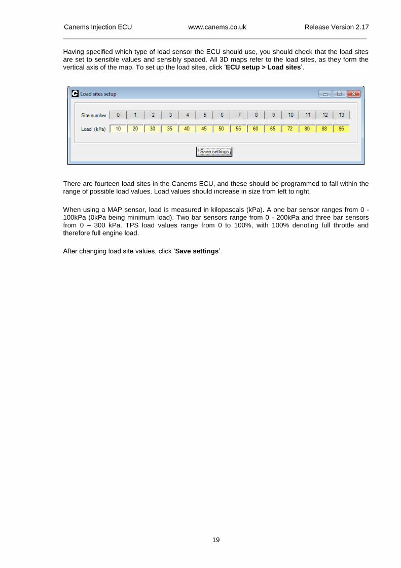
Having specified which type of load sensor the ECU should use, you should check that the load sites are set to sensible values and sensibly spaced. All 3D maps refer to the load sites, as they form the vertical axis of the map. To set up the load sites, click ‘ECU setup > Load sites’.
There are fourteen load sites in the Canems ECU, and these should be programmed to fall within the range of possible load values. Load values should increase in size from left to right.
When using a MAP sensor, load is measured in kilopascals (kPa). A one bar sensor ranges from 0 - 100kPa (0kPa being minimum load). Two bar sensors range from 0 - 200kPa and three bar sensors from 0 – 300 kPa. TPS load values range from 0 to 100%, with 100% denoting full throttle and therefore full engine load.
After changing load site values, click ‘Save settings’.
Canems Injection ECU www.canems.co.uk Release Version 2.17
___________________________________________________________________________
20
Fueling
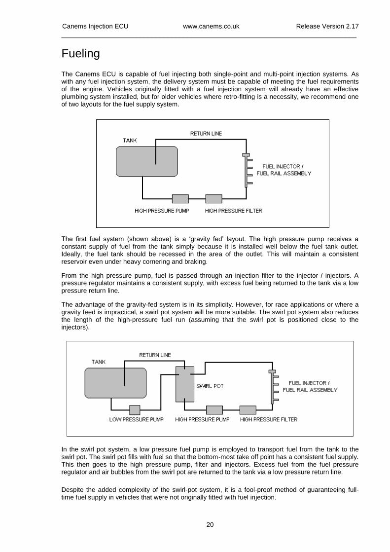
The Canems ECU is capable of fuel injecting both single-point and multi-point injection systems. As with any fuel injection system, the delivery system must be capable of meeting the fuel requirements of the engine. Vehicles originally fitted with a fuel injection system will already have an effective plumbing system installed, but for older vehicles where retro-fitting is a necessity, we recommend one of two layouts for the fuel supply system.
The first fuel system (shown above) is a ‘gravity fed’ layout. The high pressure pump receives a constant supply of fuel from the tank simply because it is installed well below the fuel tank outlet. Ideally, the fuel tank should be recessed in the area of the outlet. This will maintain a consistent reservoir even under heavy cornering and braking.
From the high pressure pump, fuel is passed through an injection filter to the injector / injectors. A pressure regulator maintains a consistent supply, with excess fuel being returned to the tank via a low pressure return line.
The advantage of the gravity-fed system is in its simplicity. However, for race applications or where a gravity feed is impractical, a swirl pot system will be more suitable. The swirl pot system also reduces the length of the high-pressure fuel run (assuming that the swirl pot is positioned close to the injectors).
In the swirl pot system, a low pressure fuel pump is employed to transport fuel from the tank to the swirl pot. The swirl pot fills with fuel so that the bottom-most take off point has a consistent fuel supply. This then goes to the high pressure pump, filter and injectors. Excess fuel from the fuel pressure regulator and air bubbles from the swirl pot are returned to the tank via a low pressure return line.
Despite the added complexity of the swirl-pot system, it is a fool-proof method of guaranteeing full-time fuel supply in vehicles that were not originally fitted with fuel injection.
Canems Injection ECU www.canems.co.uk Release Version 2.17
___________________________________________________________________________
21
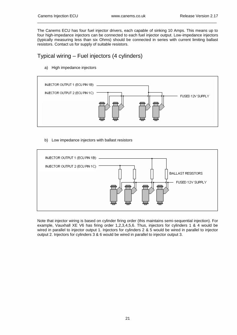
The Canems ECU has four fuel injector drivers, each capable of sinking 10 Amps. This means up to four high-impedance injectors can be connected to each fuel injector output. Low-impedance injectors (typically measuring less than six Ohms) should be connected in series with current limiting ballast resistors. Contact us for supply of suitable resistors.
Typical wiring – Fuel injectors (4 cylinders)
a) High impedance injectors
b) Low impedance injectors with ballast resistors
Note that injector wiring is based on cylinder firing order (this maintains semi-sequential injection). For example, Vauxhall XE V6 has firing order 1,2,3,4,5,6. Thus, injectors for cylinders 1 & 4 would be wired in parallel to injector output 1. Injectors for cylinders 2 & 5 would be wired in parallel to injector output 2. Injectors for cylinders 3 & 6 would be wired in parallel to injector output 3.
Canems Injection ECU www.canems.co.uk Release Version 2.17
___________________________________________________________________________
22
Injector opening times
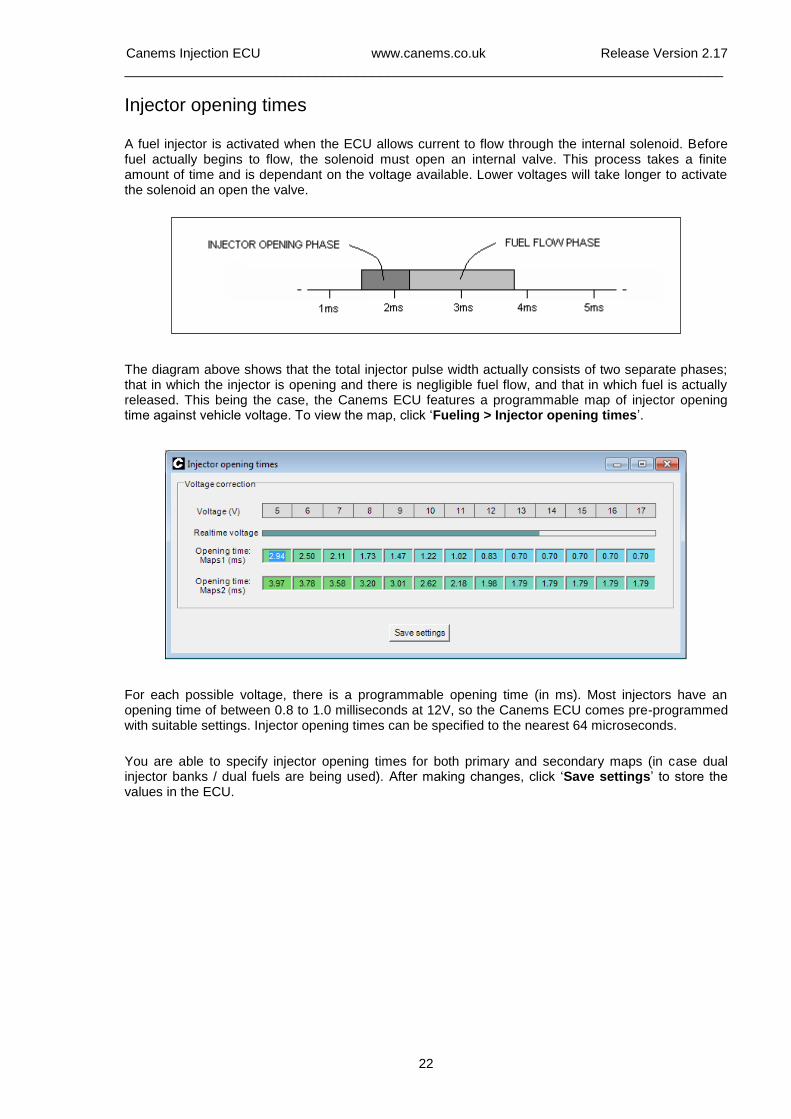
A fuel injector is activated when the ECU allows current to flow through the internal solenoid. Before fuel actually begins to flow, the solenoid must open an internal valve. This process takes a finite amount of time and is dependant on the voltage available. Lower voltages will take longer to activate the solenoid an open the valve.
The diagram above shows that the total injector pulse width actually consists of two separate phases; that in which the injector is opening and there is negligible fuel flow, and that in which fuel is actually released. This being the case, the Canems ECU features a programmable map of injector opening time against vehicle voltage. To view the map, click ‘Fueling > Injector opening times’.
For each possible voltage, there is a programmable opening time (in ms). Most injectors have an opening time of between 0.8 to 1.0 milliseconds at 12V, so the Canems ECU comes pre-programmed with suitable settings. Injector opening times can be specified to the nearest 64 microseconds.
You are able to specify injector opening times for both primary and secondary maps (in case dual injector banks / dual fuels are being used). After making changes, click ‘Save settings’ to store the values in the ECU.
Canems Injection ECU www.canems.co.uk Release Version 2.17
___________________________________________________________________________
23
Priming, cranking and after-start settings
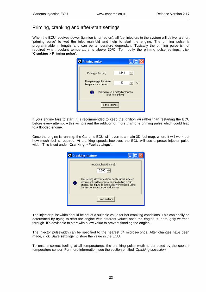
When the ECU receives power (ignition is turned on), all fuel injectors in the system will deliver a short ‘priming pulse’ to wet the inlet manifold and help to start the engine. The priming pulse is programmable in length, and can be temperature dependant. Typically the priming pulse is not required when coolant temperature is above 30ºC. To modify the priming pulse settings, click ‘Cranking > Priming pulse’.
If your engine fails to start, it is recommended to keep the ignition on rather than restarting the ECU before every attempt – this will prevent the addition of more than one priming pulse which could lead to a flooded engine.
Once the engine is running, the Canems ECU will revert to a main 3D fuel map, where it will work out how much fuel is required. At cranking speeds however, the ECU will use a preset injector pulse width. This is set under ‘Cranking > Fuel settings’.
The injector pulsewidth should be set at a suitable value for hot cranking conditions. This can easily be determined by trying to start the engine with different values once the engine is thoroughly warmed through. It’s advisable to start with a low value to prevent flooding the engine.
The injector pulsewidth can be specified to the nearest 64 microseconds. After changes have been made, click ‘Save settings’ to store the value in the ECU.
To ensure correct fueling at all temperatures, the cranking pulse width is corrected by the coolant temperature sensor. For more information, see the section entitled ‘Cranking correction’.
Canems Injection ECU www.canems.co.uk Release Version 2.17
___________________________________________________________________________
24
Once the engine has fired, the ECU will enter a condition known as ‘after start enrichment’. The aim of this is to richen the mixture so that the transition from cranking to running can be performed smoothly.
To view the after start enrichment settings, click ‘Fueling > After start enrichment’. This will display the screen to the right.
The after start enrichment amount is a programmable percentage enrichment. 0% implies no enrichment, whereas 100% would double the normal amount of fuel.
The number of crankshaft rotations for which this enrichment is applied can also be specified. During this period, the fuel enrichment will gradually decay so that by the end of the after start enrichment period the ECU will be operating solely from the main fuel maps.
With correct settings, there should be a smooth transition between cranking and running conditions. As with other values, click ‘Save settings’ to store new settings in the ECU memory.
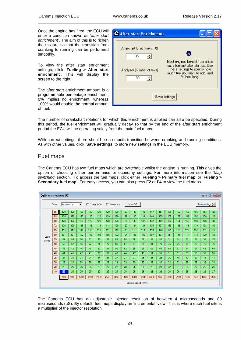
Fuel maps
The Canems ECU has two fuel maps which are switchable whilst the engine is running. This gives the option of choosing either performance or economy settings. For more information see the ‘Map switching’ section. To access the fuel maps, click either ‘Fueling > Primary fuel map’ or ‘Fueling > Secondary fuel map’. For easy access, you can also press F2 or F4 to view the fuel maps.
The Canems ECU has an adjustable injector resolution of between 4 microseconds and 80 microseconds (µS). By default, fuel maps display an ‘incremental’ view. This is where each fuel site is a multiplier of the injector resolution.
Canems Injection ECU www.canems.co.uk Release Version 2.17
___________________________________________________________________________
25
To set the resolution, click ‘Fueling > Injector resolution / MSPB’. Here you can specify the multiplier (actually measured in microseconds per bit, or MSPB). For large fuel injectors you will typically use a small MSPB figure. This increases the accuracy with which you are able to control fueling.
Note that fuel maps can only accept a value of between 0 and 255, so if you use small injectors and a small MPSB value you may actually run short of fuel under full power. To correct this, increase the MPSB value and tick ‘Rescale fuel maps to suit new resolution’; this will automatically correct your fuel maps without you needing to start from scratch on your mapping work.
As an example of fuel injector operation, if your MSPB figure is set to 64 microseconds, a fuel site with the incremental value ‘54’ would actually hold the injector open for
54 x 64 = 3456 µS (or 3.456 milliseconds)
This figure excludes the injector opening time and any acceleration enrichments which are also added on to calculate the total injector pulse width.
In the Canems ECU, fuel is normally injected once per crankshaft revolution. Therefore, if a single injector supplies fuel to a single cylinder, the total injector pulse width per 720º cycle is double the figure shown above. Canems can also cater for single point injection cars however, which may require more than one injection pulse per crankshaft revolution.
To program the fuel map, move to the site you want to alter using the arrow keys on your keyboard. Alternatively, you can use the cursor to select a site. You can then either type in a numerical value and press ‘Enter’ or use the ‘Page Up’ and ‘Page Down’ keys to increase or decrease the fuel quantity. Remember that every increment will add to the total injector flow time, and therefore enrichen the air fuel mixture.
To adjust more than one site at a time, you can click and drag over the sites you need to change. This will highlight them in yellow. You can then enter a new value, subtract a certain amount or add a certain amount.
Like all other maps, when you have finished making changes, click ‘Save settings’ to permanently store the changes in the ECU memory.
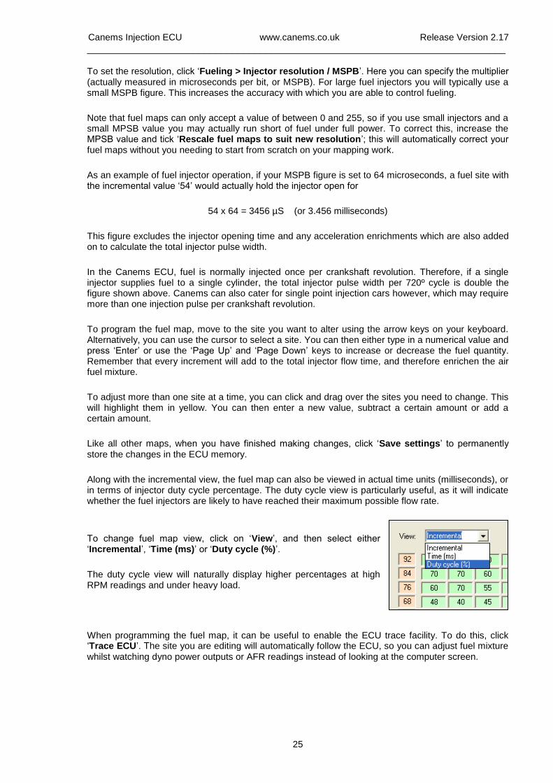
Along with the incremental view, the fuel map can also be viewed in actual time units (milliseconds), or in terms of injector duty cycle percentage. The duty cycle view is particularly useful, as it will indicate whether the fuel injectors are likely to have reached their maximum possible flow rate.
To change fuel map view, click on ‘View’, and then select either ‘Incremental’, ‘Time (ms)’ or ‘Duty cycle (%)’.
The duty cycle view will naturally display higher percentages at high RPM readings and under heavy load.
When programming the fuel map, it can be useful to enable the ECU trace facility. To do this, click ‘Trace ECU’. The site you are editing will automatically follow the ECU, so you can adjust fuel mixture whilst watching dyno power outputs or AFR readings instead of looking at the computer screen.
Canems Injection ECU www.canems.co.uk Release Version 2.17
___________________________________________________________________________
26
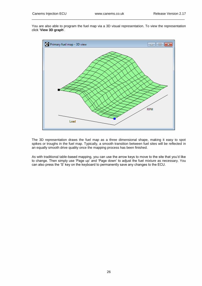
You are also able to program the fuel map via a 3D visual representation. To view the representation click ‘View 3D graph’.
The 3D representation draws the fuel map as a three dimensional shape, making it easy to spot spikes or troughs in the fuel map. Typically, a smooth transition between fuel sites will be reflected in an equally smooth drive quality once the mapping process has been finished.
As with traditional table-based mapping, you can use the arrow keys to move to the site that you’d like to change. Then simply use ‘Page up’ and ‘Page down’ to adjust the fuel mixture as necessary. You can also press the ‘S’ key on the keyboard to permanently save any changes to the ECU.
Canems Injection ECU www.canems.co.uk Release Version 2.17
___________________________________________________________________________
27
Acceleration
The main fuel maps should be programmed to provide adequate fueling for a smooth driving style under all speed and load conditions. However, under rapid acceleration or aggressive driving, extra fuel enrichment may be required. This is the equivalent of a pump jet on a carburettor.
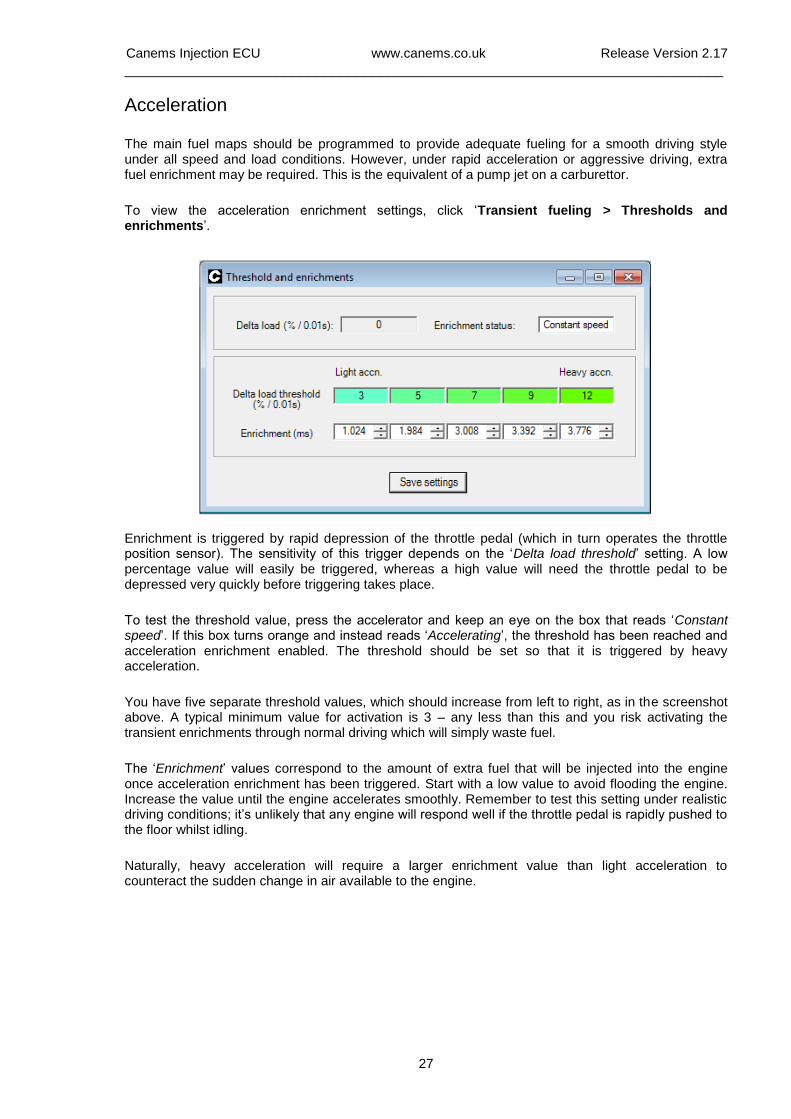
To view the acceleration enrichment settings, click ‘Transient fueling > Thresholds and enrichments’.
Enrichment is triggered by rapid depression of the throttle pedal (which in turn operates the throttle position sensor). The sensitivity of this trigger depends on the ‘Delta load threshold’ setting. A low percentage value will easily be triggered, whereas a high value will need the throttle pedal to be depressed very quickly before triggering takes place.
To test the threshold value, press the accelerator and keep an eye on the box that reads ‘Constant speed’. If this box turns orange and instead reads ‘Accelerating’, the threshold has been reached and acceleration enrichment enabled. The threshold should be set so that it is triggered by heavy acceleration.
You have five separate threshold values, which should increase from left to right, as in the screenshot above. A typical minimum value for activation is 3 – any less than this and you risk activating the transient enrichments through normal driving which will simply waste fuel.
The ‘Enrichment’ values correspond to the amount of extra fuel that will be injected into the engine once acceleration enrichment has been triggered. Start with a low value to avoid flooding the engine. Increase the value until the engine accelerates smoothly. Remember to test this setting under realistic driving conditions; it’s unlikely that any engine will respond well if the throttle pedal is rapidly pushed to the floor whilst idling.
Naturally, heavy acceleration will require a larger enrichment value than light acceleration to counteract the sudden change in air available to the engine.
Canems Injection ECU www.canems.co.uk Release Version 2.17
___________________________________________________________________________
28
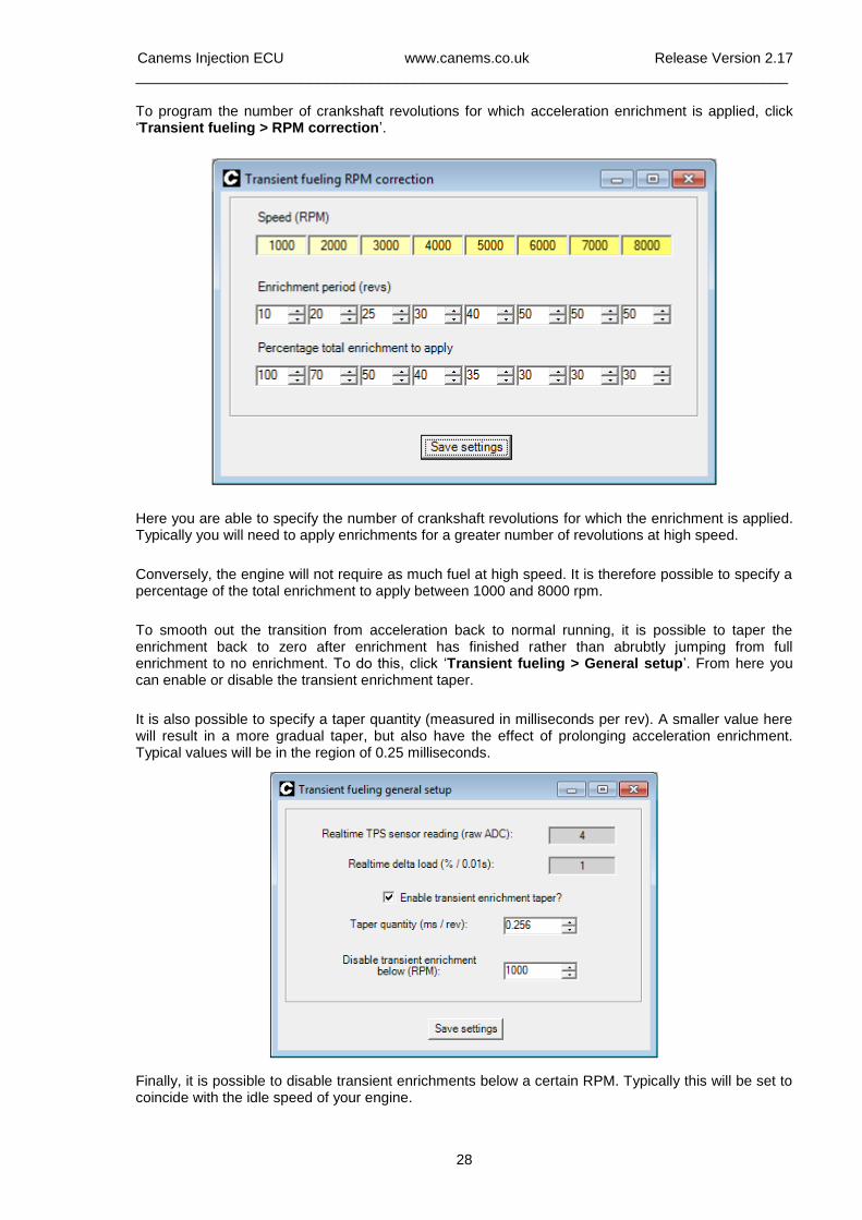
To program the number of crankshaft revolutions for which acceleration enrichment is applied, click ‘Transient fueling > RPM correction’.
Here you are able to specify the number of crankshaft revolutions for which the enrichment is applied. Typically you will need to apply enrichments for a greater number of revolutions at high speed.
Conversely, the engine will not require as much fuel at high speed. It is therefore possible to specify a percentage of the total enrichment to apply between 1000 and 8000 rpm.
To smooth out the transition from acceleration back to normal running, it is possible to taper the enrichment back to zero after enrichment has finished rather than abrubtly jumping from full enrichment to no enrichment. To do this, click ‘Transient fueling > General setup’. From here you can enable or disable the transient enrichment taper.
It is also possible to specify a taper quantity (measured in milliseconds per rev). A smaller value here will result in a more gradual taper, but also have the effect of prolonging acceleration enrichment. Typical values will be in the region of 0.25 milliseconds.
Finally, it is possible to disable transient enrichments below a certain RPM. Typically this will be set to coincide with the idle speed of your engine.
Canems Injection ECU www.canems.co.uk Release Version 2.17
___________________________________________________________________________
29
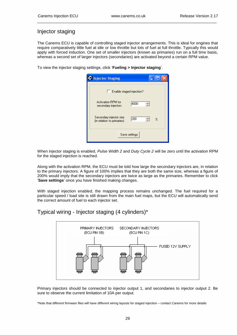
Injector staging
The Canems ECU is capable of controlling staged injector arrangements. This is ideal for engines that require comparatively little fuel at idle or low throttle but lots of fuel at full throttle. Typically this would apply with forced induction. One set of smaller injectors (known as primaries) run on a full time basis, whereas a second set of larger injectors (secondaries) are activated beyond a certain RPM value.
To view the injector staging settings, click ‘Fueling > Injector staging’.
When injector staging is enabled, Pulse Width 2 and Duty Cycle 2 will be zero until the activation RPM for the staged injection is reached.
Along with the activation RPM, the ECU must be told how large the secondary injectors are, in relation to the primary injectors. A figure of 100% implies that they are both the same size, whereas a figure of 200% would imply that the secondary injectors are twice as large as the primaries. Remember to click ‘Save settings’ once you have finished making changes.
With staged injection enabled, the mapping process remains unchanged. The fuel required for a particular speed / load site is still drawn from the main fuel maps, but the ECU will automatically send the correct amount of fuel to each injector set.
Typical wiring - Injector staging (4 cylinders)*
Primary injectors should be connected to injector output 1, and secondaries to injector output 2. Be sure to observe the current limitation of 10A per output.
*Note that different firmware files will have different wiring layouts for staged injection – contact Canems for more details
Canems Injection ECU www.canems.co.uk Release Version 2.17
___________________________________________________________________________
30
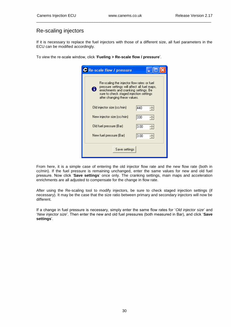
Re-scaling injectors
If it is necessary to replace the fuel injectors with those of a different size, all fuel parameters in the ECU can be modified accordingly.
To view the re-scale window, click ‘Fueling > Re-scale flow / pressure’.
From here, it is a simple case of entering the old injector flow rate and the new flow rate (both in cc/min). If the fuel pressure is remaining unchanged, enter the same values for new and old fuel pressure. Now click ‘Save settings’ once only. The cranking settings, main maps and acceleration enrichments are all adjusted to compensate for the change in flow rate.
After using the Re-scaling tool to modify injectors, be sure to check staged injection settings (if necessary). It may be the case that the size ratio between primary and secondary injectors will now be different.
If a change in fuel pressure is necessary, simply enter the same flow rates for ‘Old injector size’ and ‘New injector size’. Then enter the new and old fuel pressures (both measured in Bar), and click ‘Save settings’.
Canems Injection ECU www.canems.co.uk Release Version 2.17
___________________________________________________________________________
31
Ignition The Canems ECU supports distributorless or distributor-based ignition for engines of up to eight cylinders. The ECU can operate ignition independently from fuel injection, so programmable ignition can be achieved whilst still running carburettors.
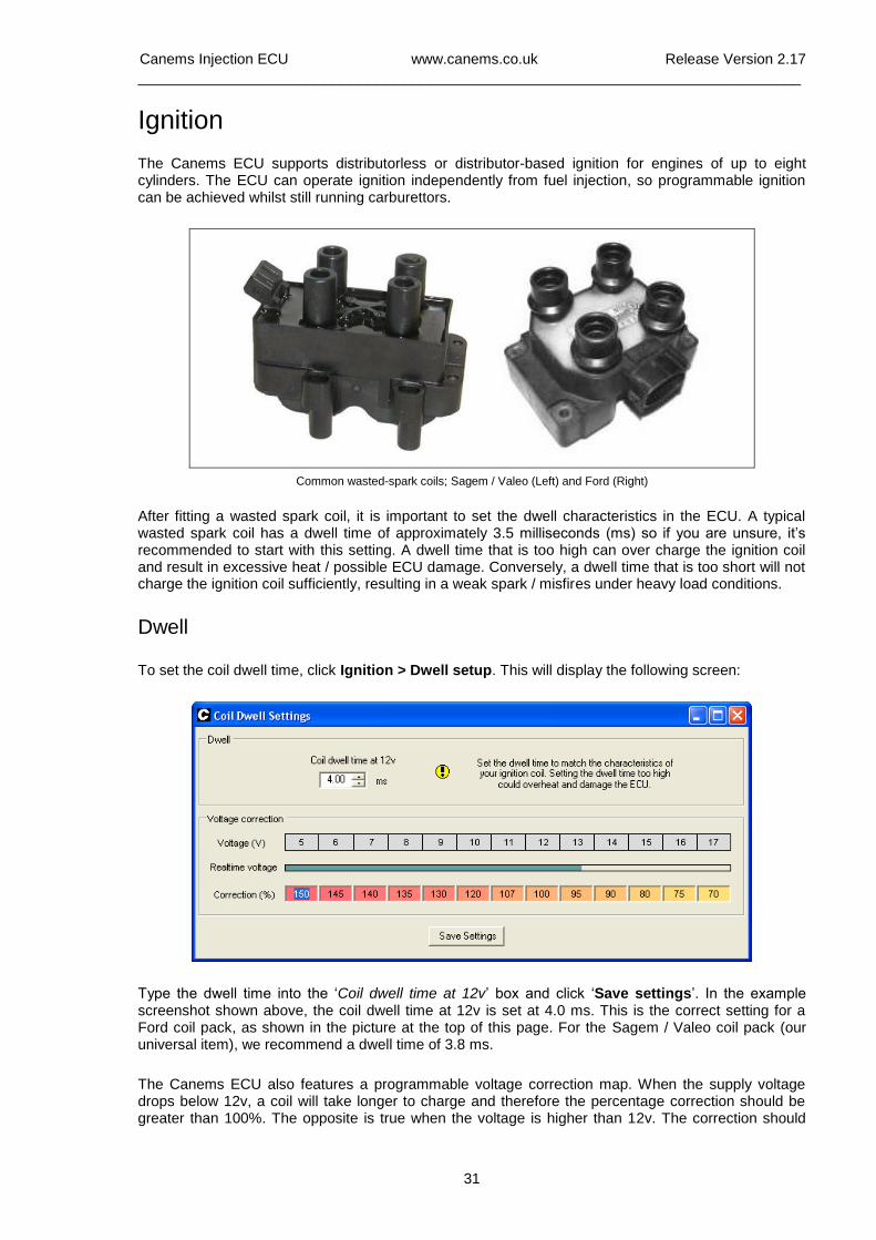
Common wasted-spark coils; Sagem / Valeo (Left) and Ford (Right)
After fitting a wasted spark coil, it is important to set the dwell characteristics in the ECU. A typical wasted spark coil has a dwell time of approximately 3.5 milliseconds (ms) so if you are unsure, it’s recommended to start with this setting. A dwell time that is too high can over charge the ignition coil and result in excessive heat / possible ECU damage. Conversely, a dwell time that is too short will not charge the ignition coil sufficiently, resulting in a weak spark / misfires under heavy load conditions.
Dwell
To set the coil dwell time, click Ignition > Dwell setup. This will display the following screen:
Type the dwell time into the ‘Coil dwell time at 12v’ box and click ‘Save settings’. In the example screenshot shown above, the coil dwell time at 12v is set at 4.0 ms. This is the correct setting for a Ford coil pack, as shown in the picture at the top of this page. For the Sagem / Valeo coil pack (our universal item), we recommend a dwell time of 3.8 ms.
The Canems ECU also features a programmable voltage correction map. When the supply voltage drops below 12v, a coil will take longer to charge and therefore the percentage correction should be greater than 100%. The opposite is true when the voltage is higher than 12v. The correction should
Canems Injection ECU www.canems.co.uk Release Version 2.17
___________________________________________________________________________
32
always be set to 100% at 12v. The ECU comes pre-programmed with a typical voltage-correction map, which should be sufficient for virtually all types of ignition coil.
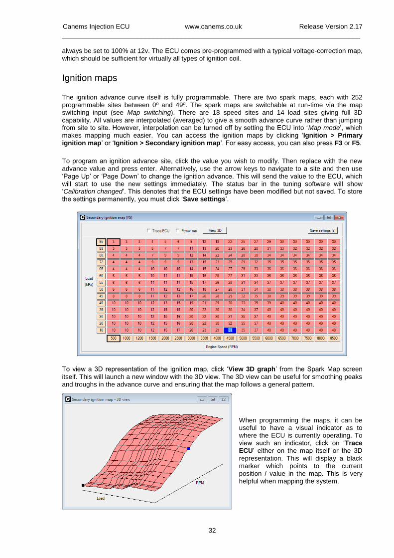
Ignition maps
The ignition advance curve itself is fully programmable. There are two spark maps, each with 252 programmable sites between 0º and 49º. The spark maps are switchable at run-time via the map switching input (see Map switching). There are 18 speed sites and 14 load sites giving full 3D capability. All values are interpolated (averaged) to give a smooth advance curve rather than jumping from site to site. However, interpolation can be turned off by setting the ECU into ‘Map mode’, which makes mapping much easier. You can access the ignition maps by clicking ‘Ignition > Primary ignition map’ or ‘Ignition > Secondary ignition map’. For easy access, you can also press F3 or F5.
To program an ignition advance site, click the value you wish to modify. Then replace with the new advance value and press enter. Alternatively, use the arrow keys to navigate to a site and then use ‘Page Up’ or ‘Page Down’ to change the ignition advance. This will send the value to the ECU, which will start to use the new settings immediately. The status bar in the tuning software will show ‘Calibration changed’. This denotes that the ECU settings have been modified but not saved. To store the settings permanently, you must click ‘Save settings’.
To view a 3D representation of the ignition map, click ‘View 3D graph’ from the Spark Map screen itself. This will launch a new window with the 3D view. The 3D view can be useful for smoothing peaks and troughs in the advance curve and ensuring that the map follows a general pattern.
When programming the maps, it can be useful to have a visual indicator as to where the ECU is currently operating. To view such an indicator, click on ‘Trace ECU’ either on the map itself or the 3D representation. This will display a black marker which points to the current position / value in the map. This is very helpful when mapping the system.
Canems Injection ECU www.canems.co.uk Release Version 2.17
___________________________________________________________________________
33
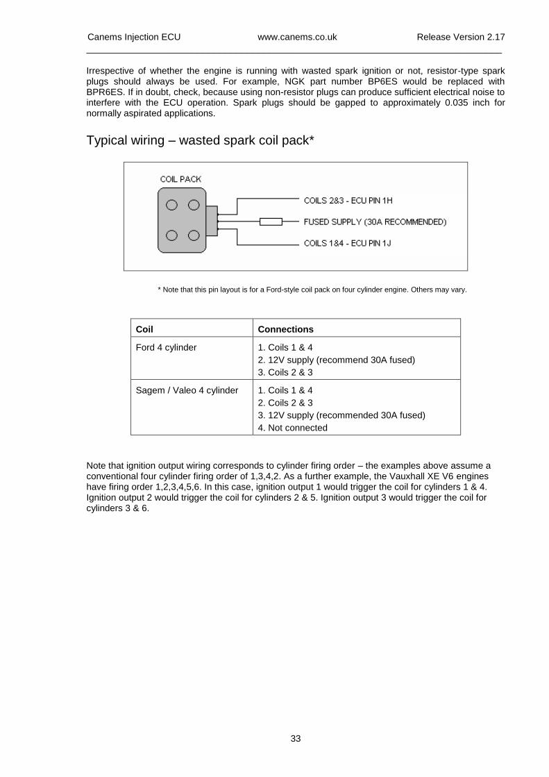
Irrespective of whether the engine is running with wasted spark ignition or not, resistor-type spark plugs should always be used. For example, NGK part number BP6ES would be replaced with BPR6ES. If in doubt, check, because using non-resistor plugs can produce sufficient electrical noise to interfere with the ECU operation. Spark plugs should be gapped to approximately 0.035 inch for normally aspirated applications.
Typical wiring – wasted spark coil pack*
* Note that this pin layout is for a Ford-style coil pack on four cylinder engine. Others may vary.
Coil
Connections
Ford 4 cylinder
1. Coils 1 & 4
2. 12V supply (recommend 30A fused)
3. Coils 2 & 3
Sagem / Valeo 4 cylinder
1. Coils 1 & 4
2. Coils 2 & 3
3. 12V supply (recommended 30A fused)
4. Not connected
Note that ignition output wiring corresponds to cylinder firing order – the examples above assume a conventional four cylinder firing order of 1,3,4,2. As a further example, the Vauxhall XE V6 engines have firing order 1,2,3,4,5,6. In this case, ignition output 1 would trigger the coil for cylinders 1 & 4. Ignition output 2 would trigger the coil for cylinders 2 & 5. Ignition output 3 would trigger the coil for cylinders 3 & 6.
Canems Injection ECU www.canems.co.uk Release Version 2.17
___________________________________________________________________________
34
Coolant temperature sensing
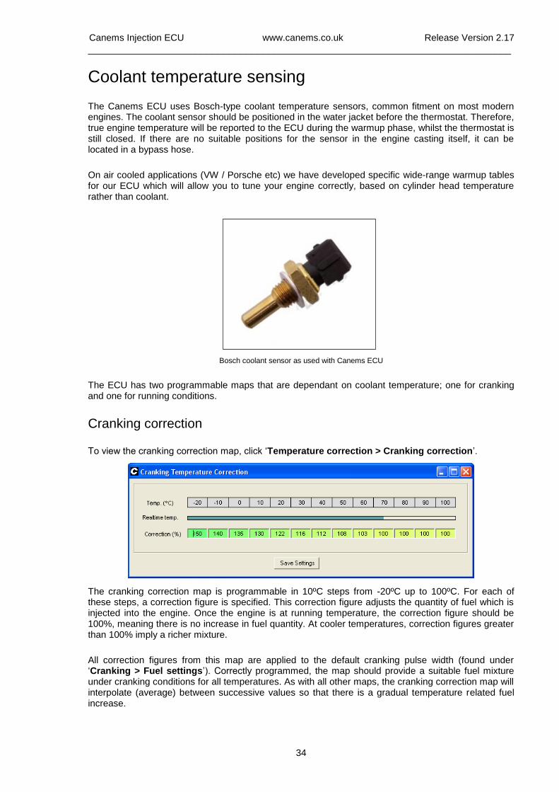
The Canems ECU uses Bosch-type coolant temperature sensors, common fitment on most modern engines. The coolant sensor should be positioned in the water jacket before the thermostat. Therefore, true engine temperature will be reported to the ECU during the warmup phase, whilst the thermostat is still closed. If there are no suitable positions for the sensor in the engine casting itself, it can be located in a bypass hose.
On air cooled applications (VW / Porsche etc) we have developed specific wide-range warmup tables for our ECU which will allow you to tune your engine correctly, based on cylinder head temperature rather than coolant.
Bosch coolant sensor as used with Canems ECU
The ECU has two programmable maps that are dependant on coolant temperature; one for cranking and one for running conditions.
Cranking correction
To view the cranking correction map, click ‘Temperature correction > Cranking correction’.
The cranking correction map is programmable in 10ºC steps from -20ºC up to 100ºC. For each of these steps, a correction figure is specified. This correction figure adjusts the quantity of fuel which is injected into the engine. Once the engine is at running temperature, the correction figure should be 100%, meaning there is no increase in fuel quantity. At cooler temperatures, correction figures greater than 100% imply a richer mixture.
All correction figures from this map are applied to the default cranking pulse width (found under ‘Cranking > Fuel settings’). Correctly programmed, the map should provide a suitable fuel mixture under cranking conditions for all temperatures. As with all other maps, the cranking correction map will interpolate (average) between successive values so that there is a gradual temperature related fuel increase.
Canems Injection ECU www.canems.co.uk Release Version 2.17
___________________________________________________________________________
35
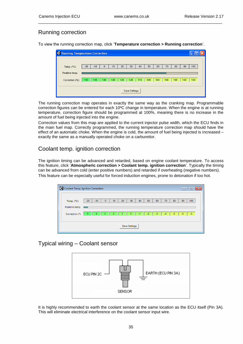
Running correction
To view the running correction map, click ‘Temperature correction > Running correction’.
The running correction map operates in exactly the same way as the cranking map. Programmable correction figures can be entered for each 10ºC change in temperature. When the engine is at running temperature, correction figure should be programmed at 100%, meaning there is no increase in the amount of fuel being injected into the engine.
Correction values from this map are applied to the current injector pulse width, which the ECU finds in the main fuel map. Correctly programmed, the running temperature correction map should have the effect of an automatic choke. When the engine is cold, the amount of fuel being injected is increased – exactly the same as a manually operated choke on a carburettor.
Coolant temp. ignition correction
The ignition timing can be advanced and retarded, based on engine coolant temperature. To access this feature, click 'Atmospheric correction > Coolant temp. ignition correction'. Typically the timing can be advanced from cold (enter positive numbers) and retarded if overheating (negative numbers).
This feature can be especially useful for forced induction engines, prone to detonation if too hot.
Typical wiring – Coolant sensor
It is highly recommended to earth the coolant sensor at the same location as the ECU itself (Pin 3A). This will eliminate electrical interference on the coolant sensor input wire.
Canems Injection ECU www.canems.co.uk Release Version 2.17
___________________________________________________________________________
36
Air temperature sensing
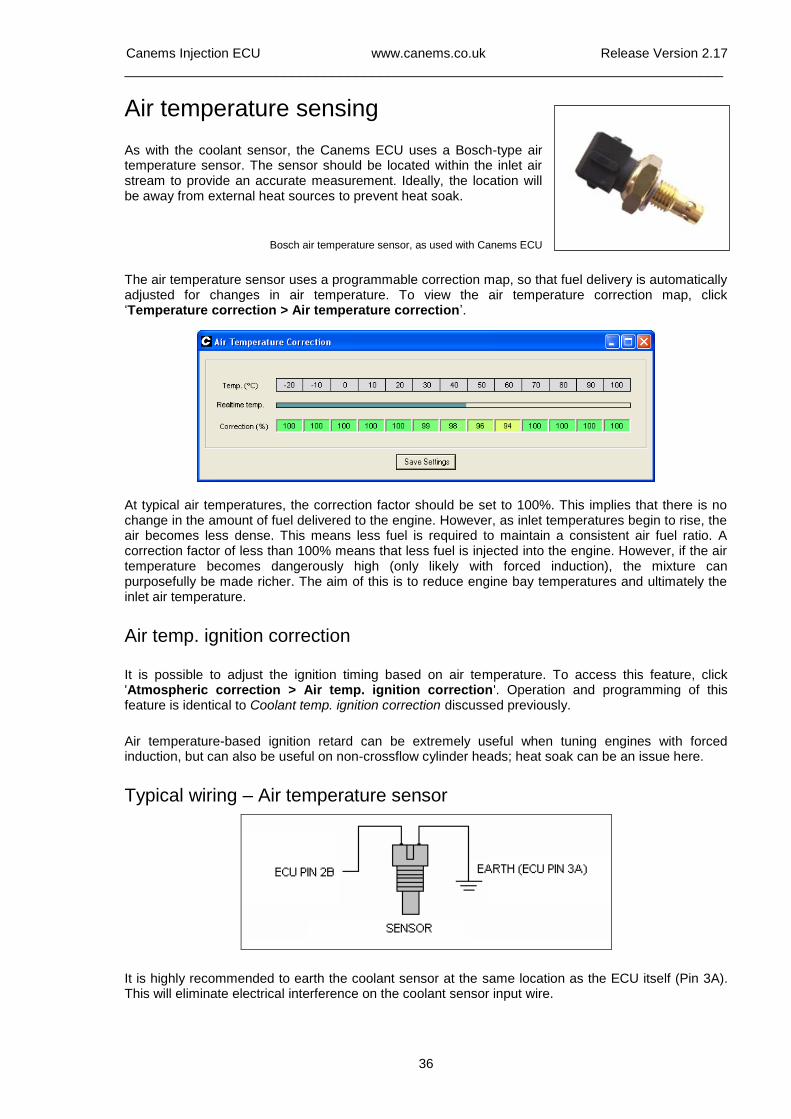
As with the coolant sensor, the Canems ECU uses a Bosch-type air temperature sensor. The sensor should be located within the inlet air stream to provide an accurate measurement. Ideally, the location will be away from external heat sources to prevent heat soak.
Bosch air temperature sensor, as used with Canems ECU
The air temperature sensor uses a programmable correction map, so that fuel delivery is automatically adjusted for changes in air temperature. To view the air temperature correction map, click ‘Temperature correction > Air temperature correction’.
At typical air temperatures, the correction factor should be set to 100%. This implies that there is no change in the amount of fuel delivered to the engine. However, as inlet temperatures begin to rise, the air becomes less dense. This means less fuel is required to maintain a consistent air fuel ratio. A correction factor of less than 100% means that less fuel is injected into the engine. However, if the air temperature becomes dangerously high (only likely with forced induction), the mixture can purposefully be made richer. The aim of this is to reduce engine bay temperatures and ultimately the inlet air temperature.
Air temp. ignition correction
It is possible to adjust the ignition timing based on air temperature. To access this feature, click 'Atmospheric correction > Air temp. ignition correction'. Operation and programming of this feature is identical to Coolant temp. ignition correction discussed previously.
Air temperature-based ignition retard can be extremely useful when tuning engines with forced induction, but can also be useful on non-crossflow cylinder heads; heat soak can be an issue here.
Typical wiring – Air temperature sensor
It is highly recommended to earth the coolant sensor at the same location as the ECU itself (Pin 3A). This will eliminate electrical interference on the coolant sensor input wire.
Canems Injection ECU www.canems.co.uk Release Version 2.17
___________________________________________________________________________
37
Oxygen sensing / feedback
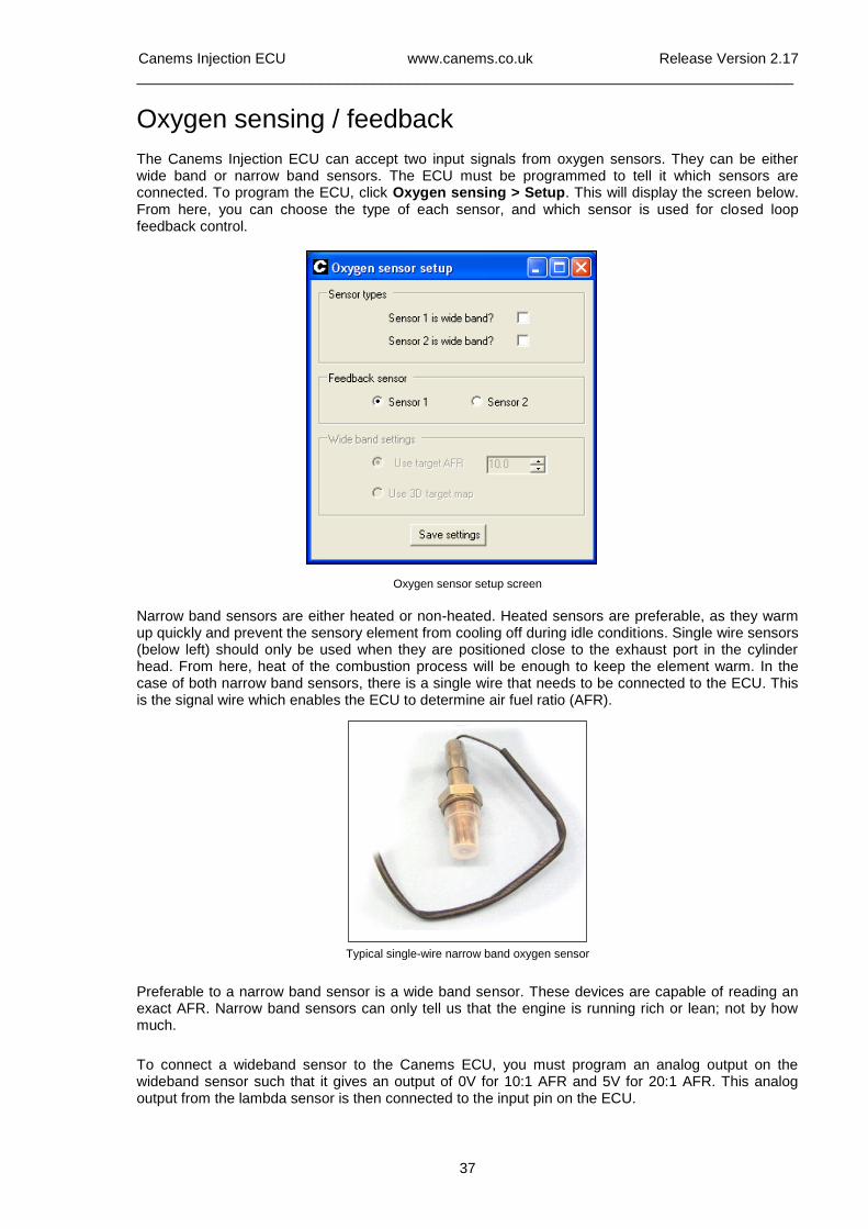
The Canems Injection ECU can accept two input signals from oxygen sensors. They can be either wide band or narrow band sensors. The ECU must be programmed to tell it which sensors are connected. To program the ECU, click Oxygen sensing > Setup. This will display the screen below. From here, you can choose the type of each sensor, and which sensor is used for closed loop feedback control.
Oxygen sensor setup screen
Narrow band sensors are either heated or non-heated. Heated sensors are preferable, as they warm up quickly and prevent the sensory element from cooling off during idle conditions. Single wire sensors (below left) should only be used when they are positioned close to the exhaust port in the cylinder head. From here, heat of the combustion process will be enough to keep the element warm. In the case of both narrow band sensors, there is a single wire that needs to be connected to the ECU. This is the signal wire which enables the ECU to determine air fuel ratio (AFR).
Typical single-wire narrow band oxygen sensor
Preferable to a narrow band sensor is a wide band sensor. These devices are capable of reading an exact AFR. Narrow band sensors can only tell us that the engine is running rich or lean; not by how much.
To connect a wideband sensor to the Canems ECU, you must program an analog output on the wideband sensor such that it gives an output of 0V for 10:1 AFR and 5V for 20:1 AFR. This analog output from the lambda sensor is then connected to the input pin on the ECU.
Canems Injection ECU www.canems.co.uk Release Version 2.17
___________________________________________________________________________
38
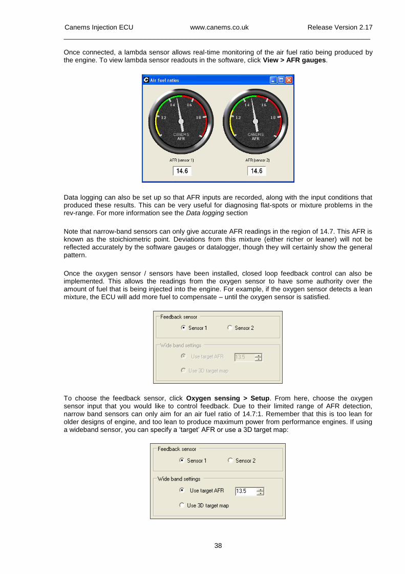
Once connected, a lambda sensor allows real-time monitoring of the air fuel ratio being produced by the engine. To view lambda sensor readouts in the software, click View > AFR gauges.
Data logging can also be set up so that AFR inputs are recorded, along with the input conditions that produced these results. This can be very useful for diagnosing flat-spots or mixture problems in the rev-range. For more information see the Data logging section
Note that narrow-band sensors can only give accurate AFR readings in the region of 14.7. This AFR is known as the stoichiometric point. Deviations from this mixture (either richer or leaner) will not be reflected accurately by the software gauges or datalogger, though they will certainly show the general pattern.
Once the oxygen sensor / sensors have been installed, closed loop feedback control can also be implemented. This allows the readings from the oxygen sensor to have some authority over the amount of fuel that is being injected into the engine. For example, if the oxygen sensor detects a lean mixture, the ECU will add more fuel to compensate – until the oxygen sensor is satisfied.
To choose the feedback sensor, click Oxygen sensing > Setup. From here, choose the oxygen sensor input that you would like to control feedback. Due to their limited range of AFR detection, narrow band sensors can only aim for an air fuel ratio of 14.7:1. Remember that this is too lean for older designs of engine, and too lean to produce maximum power from performance engines. If using a wideband sensor, you can specify a ‘target’ AFR or use a 3D target map:
Canems Injection ECU www.canems.co.uk Release Version 2.17
___________________________________________________________________________
39
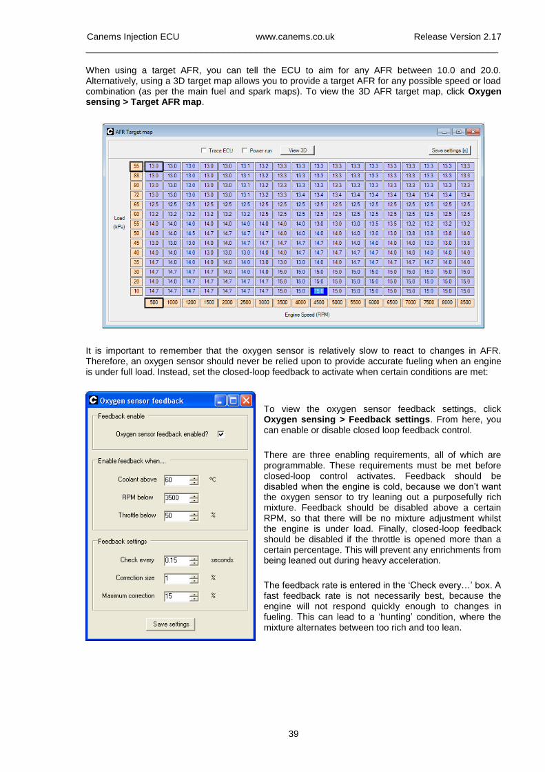
When using a target AFR, you can tell the ECU to aim for any AFR between 10.0 and 20.0. Alternatively, using a 3D target map allows you to provide a target AFR for any possible speed or load combination (as per the main fuel and spark maps). To view the 3D AFR target map, click Oxygen sensing > Target AFR map.
It is important to remember that the oxygen sensor is relatively slow to react to changes in AFR. Therefore, an oxygen sensor should never be relied upon to provide accurate fueling when an engine is under full load. Instead, set the closed-loop feedback to activate when certain conditions are met:
To view the oxygen sensor feedback settings, click Oxygen sensing > Feedback settings. From here, you can enable or disable closed loop feedback control.
There are three enabling requirements, all of which are programmable. These requirements must be met before closed-loop control activates. Feedback should be disabled when the engine is cold, because we don’t want the oxygen sensor to try leaning out a purposefully rich mixture. Feedback should be disabled above a certain RPM, so that there will be no mixture adjustment whilst the engine is under load. Finally, closed-loop feedback should be disabled if the throttle is opened more than a certain percentage. This will prevent any enrichments from being leaned out during heavy acceleration.
The feedback rate is entered in the ‘Check every…’ box. A fast feedback rate is not necessarily best, because the engine will not respond quickly enough to changes in fueling. This can lead to a ‘hunting’ condition, where the mixture alternates between too rich and too lean.
Canems Injection ECU www.canems.co.uk Release Version 2.17
___________________________________________________________________________
40
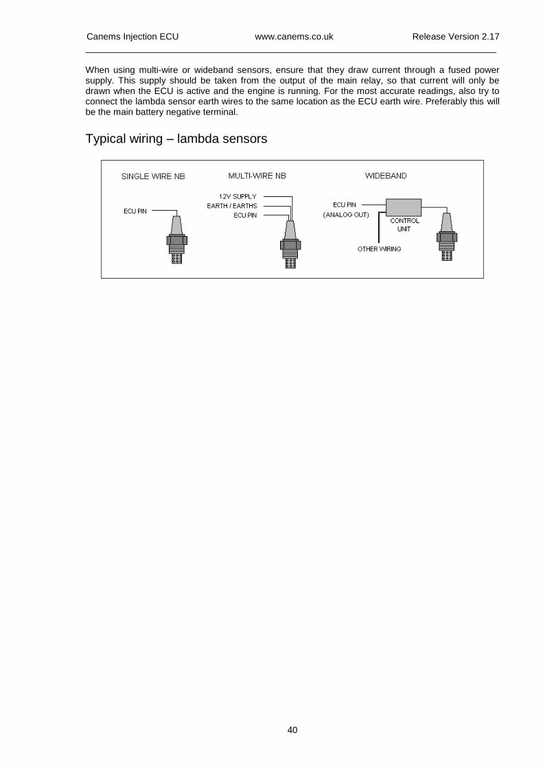
When using multi-wire or wideband sensors, ensure that they draw current through a fused power supply. This supply should be taken from the output of the main relay, so that current will only be drawn when the ECU is active and the engine is running. For the most accurate readings, also try to connect the lambda sensor earth wires to the same location as the ECU earth wire. Preferably this will be the main battery negative terminal.
Typical wiring – lambda sensors
Canems Injection ECU www.canems.co.uk Release Version 2.17
___________________________________________________________________________
41
Barometric pressure correction
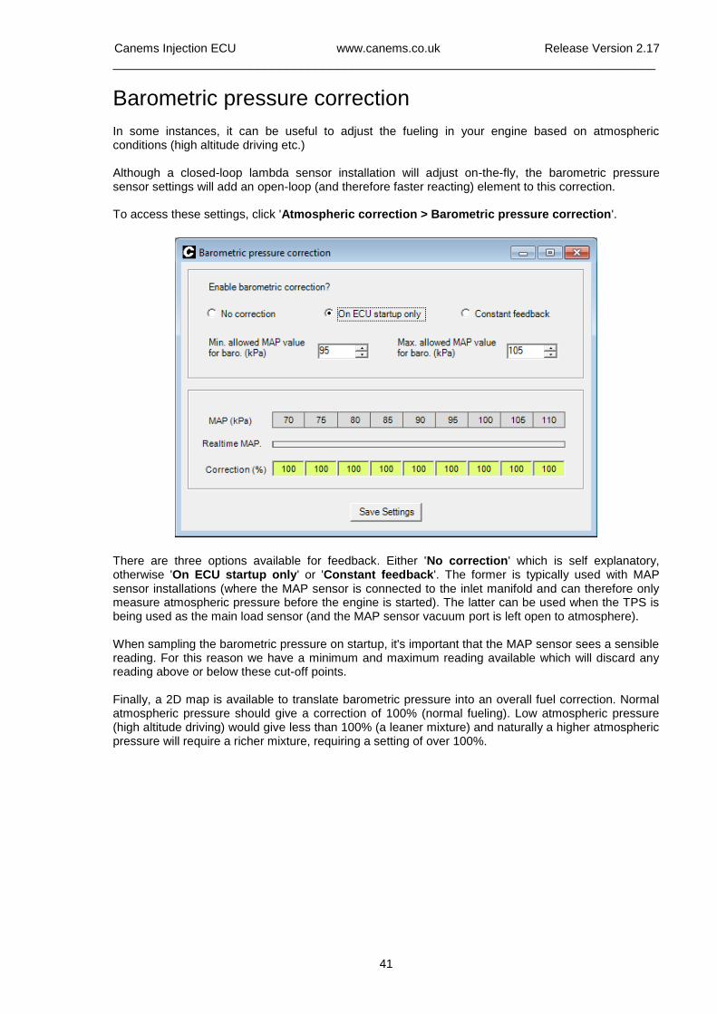
In some instances, it can be useful to adjust the fueling in your engine based on atmospheric conditions (high altitude driving etc.) Although a closed-loop lambda sensor installation will adjust on-the-fly, the barometric pressure sensor settings will add an open-loop (and therefore faster reacting) element to this correction. To access these settings, click 'Atmospheric correction > Barometric pressure correction'. There are three options available for feedback. Either 'No correction' which is self explanatory, otherwise 'On ECU startup only' or 'Constant feedback'. The former is typically used with MAP sensor installations (where the MAP sensor is connected to the inlet manifold and can therefore only measure atmospheric pressure before the engine is started). The latter can be used when the TPS is being used as the main load sensor (and the MAP sensor vacuum port is left open to atmosphere). When sampling the barometric pressure on startup, it's important that the MAP sensor sees a sensible reading. For this reason we have a minimum and maximum reading available which will discard any reading above or below these cut-off points. Finally, a 2D map is available to translate barometric pressure into an overall fuel correction. Normal atmospheric pressure should give a correction of 100% (normal fueling). Low atmospheric pressure (high altitude driving) would give less than 100% (a leaner mixture) and naturally a higher atmospheric pressure will require a richer mixture, requiring a setting of over 100%.
Canems Injection ECU www.canems.co.uk Release Version 2.17
___________________________________________________________________________
42
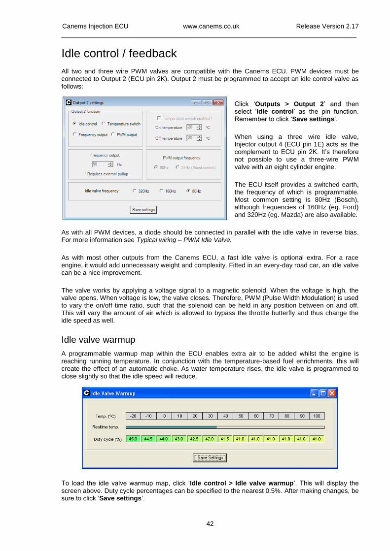
Idle control / feedback All two and three wire PWM valves are compatible with the Canems ECU. PWM devices must be connected to Output 2 (ECU pin 2K). Output 2 must be programmed to accept an idle control valve as follows:
Click ‘Outputs > Output 2’ and then select ‘Idle control’ as the pin function. Remember to click ‘Save settings’.
When using a three wire idle valve, Injector output 4 (ECU pin 1E) acts as the complement to ECU pin 2K. It’s therefore not possible to use a three-wire PWM valve with an eight cylinder engine.
The ECU itself provides a switched earth, the frequency of which is programmable. Most common setting is 80Hz (Bosch), although frequencies of 160Hz (eg. Ford) and 320Hz (eg. Mazda) are also available.
As with all PWM devices, a diode should be connected in parallel with the idle valve in reverse bias. For more information see Typical wiring – PWM Idle Valve.
As with most other outputs from the Canems ECU, a fast idle valve is optional extra. For a race engine, it would add unnecessary weight and complexity. Fitted in an every-day road car, an idle valve can be a nice improvement.
The valve works by applying a voltage signal to a magnetic solenoid. When the voltage is high, the valve opens. When voltage is low, the valve closes. Therefore, PWM (Pulse Width Modulation) is used to vary the on/off time ratio, such that the solenoid can be held in any position between on and off. This will vary the amount of air which is allowed to bypass the throttle butterfly and thus change the idle speed as well.
Idle valve warmup
A programmable warmup map within the ECU enables extra air to be added whilst the engine is reaching running temperature. In conjunction with the temperature-based fuel enrichments, this will create the effect of an automatic choke. As water temperature rises, the idle valve is programmed to close slightly so that the idle speed will reduce.
To load the idle valve warmup map, click ‘Idle control > Idle valve warmup’. This will display the screen above. Duty cycle percentages can be specified to the nearest 0.5%. After making changes, be sure to click ‘Save settings’.
Canems Injection ECU www.canems.co.uk Release Version 2.17
___________________________________________________________________________
43
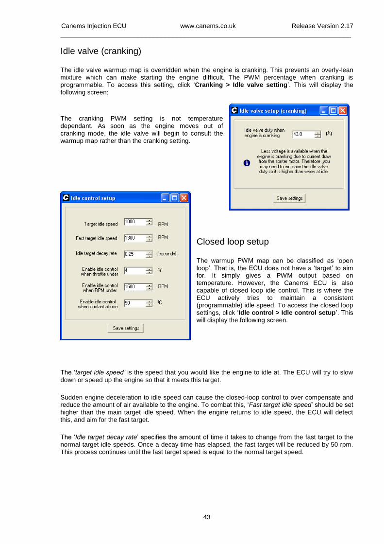
Idle valve (cranking)
The idle valve warmup map is overridden when the engine is cranking. This prevents an overly-lean mixture which can make starting the engine difficult. The PWM percentage when cranking is programmable. To access this setting, click ‘Cranking > Idle valve setting’. This will display the following screen:
The cranking PWM setting is not temperature dependant. As soon as the engine moves out of cranking mode, the idle valve will begin to consult the warmup map rather than the cranking setting.
Closed loop setup
The warmup PWM map can be classified as ‘open loop’. That is, the ECU does not have a ‘target’ to aim for. It simply gives a PWM output based on temperature. However, the Canems ECU is also capable of closed loop idle control. This is where the ECU actively tries to maintain a consistent (programmable) idle speed. To access the closed loop settings, click ‘Idle control > Idle control setup’. This will display the following screen.
The ‘target idle speed’ is the speed that you would like the engine to idle at. The ECU will try to slow down or speed up the engine so that it meets this target.
Sudden engine deceleration to idle speed can cause the closed-loop control to over compensate and reduce the amount of air available to the engine. To combat this, ‘Fast target idle speed’ should be set higher than the main target idle speed. When the engine returns to idle speed, the ECU will detect this, and aim for the fast target.
The ‘Idle target decay rate’ specifies the amount of time it takes to change from the fast target to the normal target idle speeds. Once a decay time has elapsed, the fast target will be reduced by 50 rpm. This process continues until the fast target speed is equal to the normal target speed.
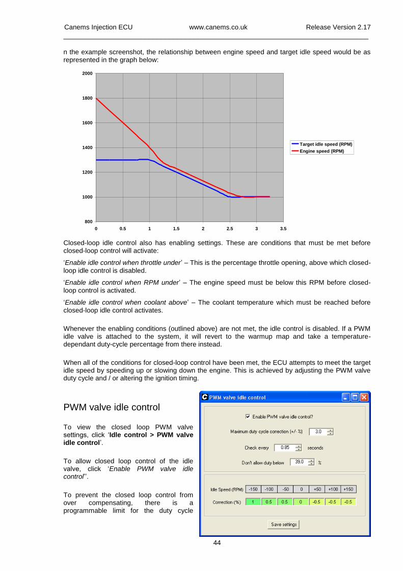
Canems Injection ECU www.canems.co.uk Release Version 2.17
___________________________________________________________________________
44
n the example screenshot, the relationship between engine speed and target idle speed would be as represented in the graph below:
800
1000
1200
1400
1600
1800
2000
0 0.5 1 1.5 2 2.5 3 3.5
Target idle speed (RPM)
Engine speed (RPM)
Closed-loop idle control also has enabling settings. These are conditions that must be met before closed-loop control will activate:
‘Enable idle control when throttle under’ – This is the percentage throttle opening, above which closed-loop idle control is disabled.
‘Enable idle control when RPM under’ – The engine speed must be below this RPM before closed-loop control is activated.
‘Enable idle control when coolant above’ – The coolant temperature which must be reached before closed-loop idle control activates.
Whenever the enabling conditions (outlined above) are not met, the idle control is disabled. If a PWM idle valve is attached to the system, it will revert to the warmup map and take a temperature-dependant duty-cycle percentage from there instead.
When all of the conditions for closed-loop control have been met, the ECU attempts to meet the target idle speed by speeding up or slowing down the engine. This is achieved by adjusting the PWM valve duty cycle and / or altering the ignition timing.
PWM valve idle control
To view the closed loop PWM valve settings, click ‘Idle control > PWM valve idle control’.
To allow closed loop control of the idle valve, click ‘Enable PWM valve idle control’’.
To prevent the closed loop control from over compensating, there is a programmable limit for the duty cycle
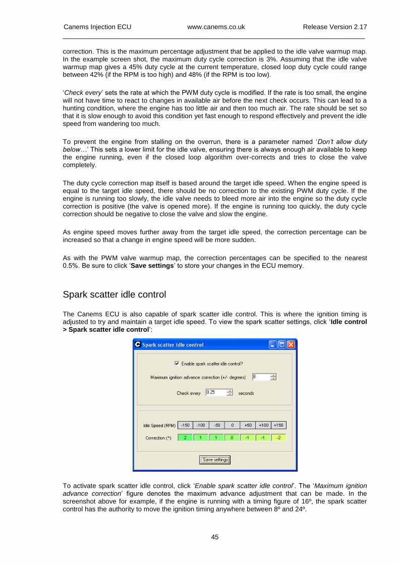
Canems Injection ECU www.canems.co.uk Release Version 2.17
___________________________________________________________________________
45
correction. This is the maximum percentage adjustment that be applied to the idle valve warmup map. In the example screen shot, the maximum duty cycle correction is 3%. Assuming that the idle valve warmup map gives a 45% duty cycle at the current temperature, closed loop duty cycle could range between 42% (if the RPM is too high) and 48% (if the RPM is too low).
‘Check every’ sets the rate at which the PWM duty cycle is modified. If the rate is too small, the engine will not have time to react to changes in available air before the next check occurs. This can lead to a hunting condition, where the engine has too little air and then too much air. The rate should be set so that it is slow enough to avoid this condition yet fast enough to respond effectively and prevent the idle speed from wandering too much.
To prevent the engine from stalling on the overrun, there is a parameter named ‘Don’t allow duty below…’ This sets a lower limit for the idle valve, ensuring there is always enough air available to keep the engine running, even if the closed loop algorithm over-corrects and tries to close the valve completely.
The duty cycle correction map itself is based around the target idle speed. When the engine speed is equal to the target idle speed, there should be no correction to the existing PWM duty cycle. If the engine is running too slowly, the idle valve needs to bleed more air into the engine so the duty cycle correction is positive (the valve is opened more). If the engine is running too quickly, the duty cycle correction should be negative to close the valve and slow the engine.
As engine speed moves further away from the target idle speed, the correction percentage can be increased so that a change in engine speed will be more sudden.
As with the PWM valve warmup map, the correction percentages can be specified to the nearest 0.5%. Be sure to click ‘Save settings’ to store your changes in the ECU memory.
Spark scatter idle control
The Canems ECU is also capable of spark scatter idle control. This is where the ignition timing is adjusted to try and maintain a target idle speed. To view the spark scatter settings, click ‘Idle control > Spark scatter idle control’:
To activate spark scatter idle control, click ‘Enable spark scatter idle control’. The ‘Maximum ignition advance correction’ figure denotes the maximum advance adjustment that can be made. In the screenshot above for example, if the engine is running with a timing figure of 16º, the spark scatter control has the authority to move the ignition timing anywhere between 8º and 24º.
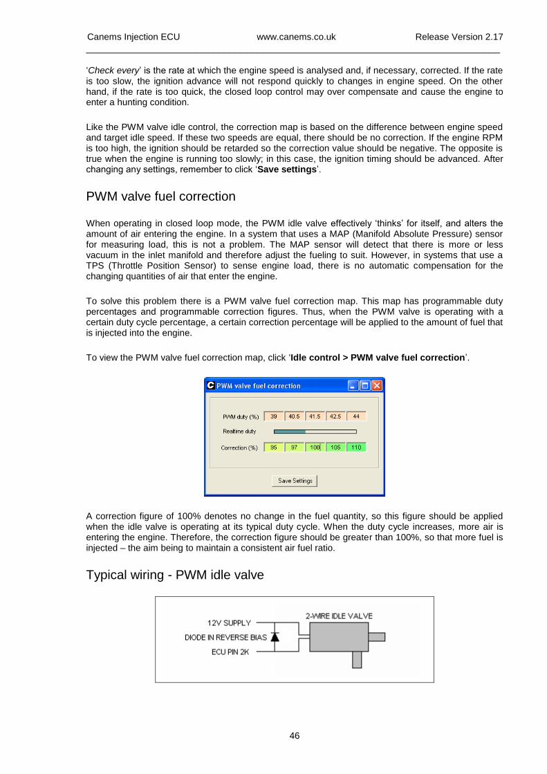
Canems Injection ECU www.canems.co.uk Release Version 2.17
___________________________________________________________________________
46
‘Check every’ is the rate at which the engine speed is analysed and, if necessary, corrected. If the rate is too slow, the ignition advance will not respond quickly to changes in engine speed. On the other hand, if the rate is too quick, the closed loop control may over compensate and cause the engine to enter a hunting condition.
Like the PWM valve idle control, the correction map is based on the difference between engine speed and target idle speed. If these two speeds are equal, there should be no correction. If the engine RPM is too high, the ignition should be retarded so the correction value should be negative. The opposite is true when the engine is running too slowly; in this case, the ignition timing should be advanced. After changing any settings, remember to click ‘Save settings’.
PWM valve fuel correction
When operating in closed loop mode, the PWM idle valve effectively ‘thinks’ for itself, and alters the amount of air entering the engine. In a system that uses a MAP (Manifold Absolute Pressure) sensor for measuring load, this is not a problem. The MAP sensor will detect that there is more or less vacuum in the inlet manifold and therefore adjust the fueling to suit. However, in systems that use a TPS (Throttle Position Sensor) to sense engine load, there is no automatic compensation for the changing quantities of air that enter the engine.
To solve this problem there is a PWM valve fuel correction map. This map has programmable duty percentages and programmable correction figures. Thus, when the PWM valve is operating with a certain duty cycle percentage, a certain correction percentage will be applied to the amount of fuel that is injected into the engine.
To view the PWM valve fuel correction map, click ‘Idle control > PWM valve fuel correction’.
A correction figure of 100% denotes no change in the fuel quantity, so this figure should be applied when the idle valve is operating at its typical duty cycle. When the duty cycle increases, more air is entering the engine. Therefore, the correction figure should be greater than 100%, so that more fuel is injected – the aim being to maintain a consistent air fuel ratio.
Typical wiring - PWM idle valve
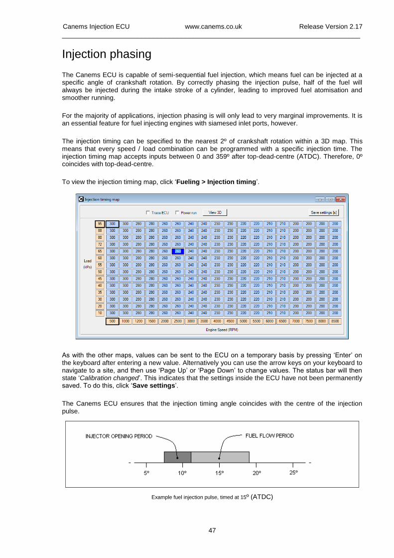
Canems Injection ECU www.canems.co.uk Release Version 2.17
___________________________________________________________________________
47
Injection phasing
The Canems ECU is capable of semi-sequential fuel injection, which means fuel can be injected at a specific angle of crankshaft rotation. By correctly phasing the injection pulse, half of the fuel will always be injected during the intake stroke of a cylinder, leading to improved fuel atomisation and smoother running.
For the majority of applications, injection phasing is will only lead to very marginal improvements. It is an essential feature for fuel injecting engines with siamesed inlet ports, however.
The injection timing can be specified to the nearest 2º of crankshaft rotation within a 3D map. This means that every speed / load combination can be programmed with a specific injection time. The injection timing map accepts inputs between 0 and 359º after top-dead-centre (ATDC). Therefore, 0º coincides with top-dead-centre.
To view the injection timing map, click ‘Fueling > Injection timing’.
As with the other maps, values can be sent to the ECU on a temporary basis by pressing ‘Enter’ on the keyboard after entering a new value. Alternatively you can use the arrow keys on your keyboard to navigate to a site, and then use ‘Page Up’ or ‘Page Down’ to change values. The status bar will then state ‘Calibration changed’. This indicates that the settings inside the ECU have not been permanently saved. To do this, click ‘Save settings’.
The Canems ECU ensures that the injection timing angle coincides with the centre of the injection pulse.
Example fuel injection pulse, timed at 15º (ATDC)
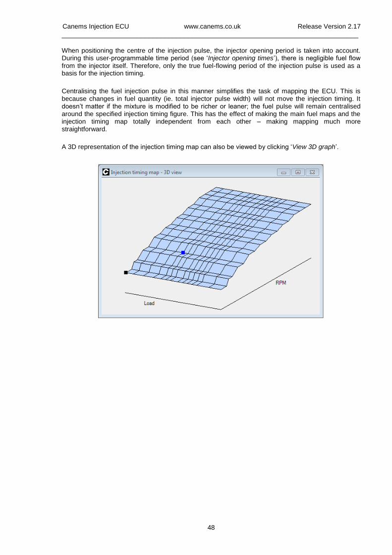
Canems Injection ECU www.canems.co.uk Release Version 2.17
___________________________________________________________________________
48
When positioning the centre of the injection pulse, the injector opening period is taken into account. During this user-programmable time period (see ‘Injector opening times’), there is negligible fuel flow from the injector itself. Therefore, only the true fuel-flowing period of the injection pulse is used as a basis for the injection timing.
Centralising the fuel injection pulse in this manner simplifies the task of mapping the ECU. This is because changes in fuel quantity (ie. total injector pulse width) will not move the injection timing. It doesn’t matter if the mixture is modified to be richer or leaner; the fuel pulse will remain centralised around the specified injection timing figure. This has the effect of making the main fuel maps and the injection timing map totally independent from each other – making mapping much more straightforward.
A 3D representation of the injection timing map can also be viewed by clicking ‘View 3D graph’.
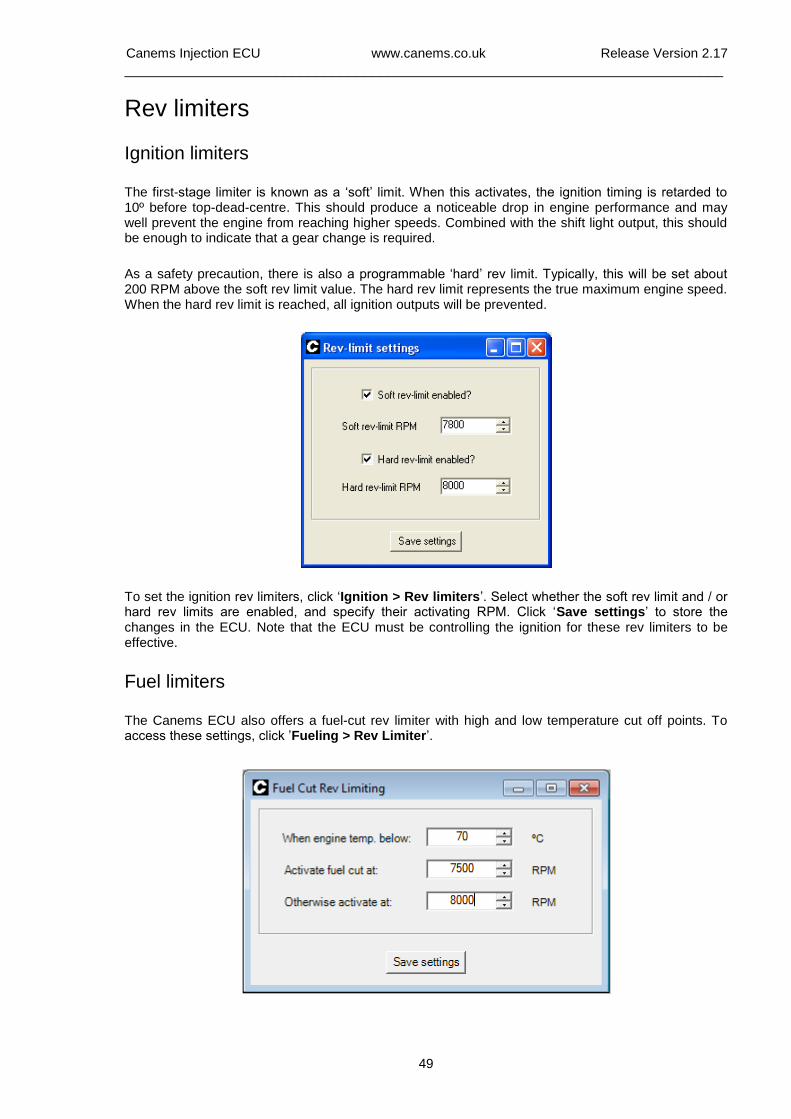
Canems Injection ECU www.canems.co.uk Release Version 2.17
___________________________________________________________________________
49
Rev limiters
Ignition limiters
The first-stage limiter is known as a ‘soft’ limit. When this activates, the ignition timing is retarded to 10º before top-dead-centre. This should produce a noticeable drop in engine performance and may well prevent the engine from reaching higher speeds. Combined with the shift light output, this should be enough to indicate that a gear change is required.
As a safety precaution, there is also a programmable ‘hard’ rev limit. Typically, this will be set about 200 RPM above the soft rev limit value. The hard rev limit represents the true maximum engine speed. When the hard rev limit is reached, all ignition outputs will be prevented.
To set the ignition rev limiters, click ‘Ignition > Rev limiters’. Select whether the soft rev limit and / or hard rev limits are enabled, and specify their activating RPM. Click ‘Save settings’ to store the changes in the ECU. Note that the ECU must be controlling the ignition for these rev limiters to be effective.
Fuel limiters
The Canems ECU also offers a fuel-cut rev limiter with high and low temperature cut off points. To access these settings, click ’Fueling > Rev Limiter’.
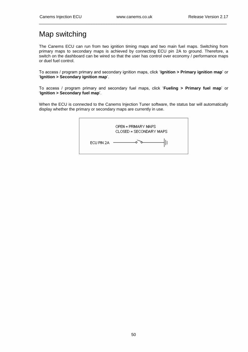
Canems Injection ECU www.canems.co.uk Release Version 2.17
___________________________________________________________________________
50
Map switching The Canems ECU can run from two ignition timing maps and two main fuel maps. Switching from primary maps to secondary maps is achieved by connecting ECU pin 2A to ground. Therefore, a switch on the dashboard can be wired so that the user has control over economy / performance maps or duel fuel control.
To access / program primary and secondary ignition maps, click ‘Ignition > Primary ignition map’ or ‘Ignition > Secondary ignition map’.
To access / program primary and secondary fuel maps, click ‘Fueling > Primary fuel map’ or ‘Ignition > Secondary fuel map’.
When the ECU is connected to the Canems Injection Tuner software, the status bar will automatically display whether the primary or secondary maps are currently in use.
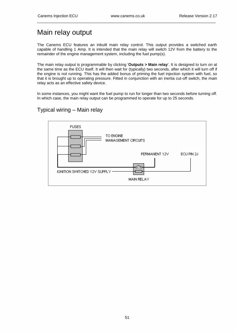
Canems Injection ECU www.canems.co.uk Release Version 2.17
___________________________________________________________________________
51
Main relay output
The Canems ECU features an inbuilt main relay control. This output provides a switched earth capable of handling 1 Amp. It is intended that the main relay will switch 12V from the battery to the remainder of the engine management system, including the fuel pump(s).
The main relay output is programmable by clicking 'Outputs > Main relay'. It is designed to turn on at the same time as the ECU itself. It will then wait for (typically) two seconds, after which it will turn off if the engine is not running. This has the added bonus of priming the fuel injection system with fuel, so that it is brought up to operating pressure. Fitted in conjunction with an inertia cut-off switch, the main relay acts as an effective safety device.
In some instances, you might want the fuel pump to run for longer than two seconds before turning off. In which case, the main relay output can be programmed to operate for up to 25 seconds.
Typical wiring – Main relay
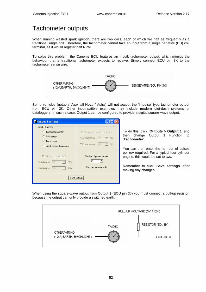
Canems Injection ECU www.canems.co.uk Release Version 2.17
___________________________________________________________________________
52
Tachometer outputs
When running wasted spark ignition, there are two coils, each of which fire half as frequently as a traditional single coil. Therefore, the tachometer cannot take an input from a single negative (CB) coil terminal, as it would register half RPM.
To solve this problem, the Canems ECU features an inbuilt tachometer output, which mimics the behaviour that a traditional tachometer expects to receive. Simply connect ECU pin 3K to the tachometer sense wire.
Some vehicles (notably Vauxhall Nova / Astra) will not accept the ‘impulse’ type tachometer output from ECU pin 3K. Other incompatible examples may include modern digi-dash systems or dataloggers. In such a case, Output 1 can be configured to provide a digital square-wave output.
To do this, click ‘Outputs > Output 1’ and then change Output 1 Function to ‘Tachometer’.
You can then enter the number of pulses per rev required. For a typical four cylinder engine, this would be set to two.
Remember to click ‘Save settings’ after making any changes.
When using the square-wave output from Output 1 (ECU pin 3J) you must connect a pull-up resistor, because the output can only provide a switched earth:
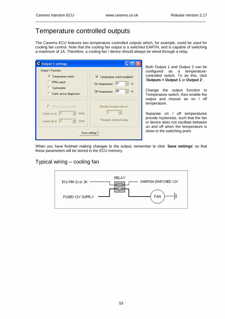
Canems Injection ECU www.canems.co.uk Release Version 2.17
___________________________________________________________________________
53
Temperature controlled outputs
The Canems ECU features two temperature controlled outputs which, for example, could be used for cooling fan control. Note that the cooling fan output is a switched EARTH, and is capable of switching a maximum of 1A. Therefore, a cooling fan / device should always be wired through a relay.
Both Output 1 and Output 2 can be configured as a temperature-controlled switch. To do this, click ‘Outputs > Output 1 or Output 2’.
Change the output function to Temperature switch, then enable the output and choose an on / off temperature.
Separate on / off temperatures provide hysteresis, such that the fan or device does not oscillate between on and off when the temperature is close to the switching point.
When you have finished making changes to the output, remember to click ‘Save settings’ so that these parameters will be stored in the ECU memory.
Typical wiring – cooling fan
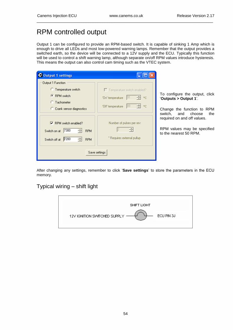
Canems Injection ECU www.canems.co.uk Release Version 2.17
___________________________________________________________________________
54
RPM controlled output
Output 1 can be configured to provide an RPM-based switch. It is capable of sinking 1 Amp which is enough to drive all LEDs and most low-powered warning lamps. Remember that the output provides a switched earth, so the device will be connected to a 12V supply and the ECU. Typically this function will be used to control a shift warning lamp, although separate on/off RPM values introduce hysteresis. This means the output can also control cam timing such as the VTEC system.
To configure the output, click ‘Outputs > Output 1’.
Change the function to RPM switch, and choose the required on and off values.
RPM values may be specified to the nearest 50 RPM.
After changing any settings, remember to click ‘Save settings’ to store the parameters in the ECU memory.
Typical wiring – shift light
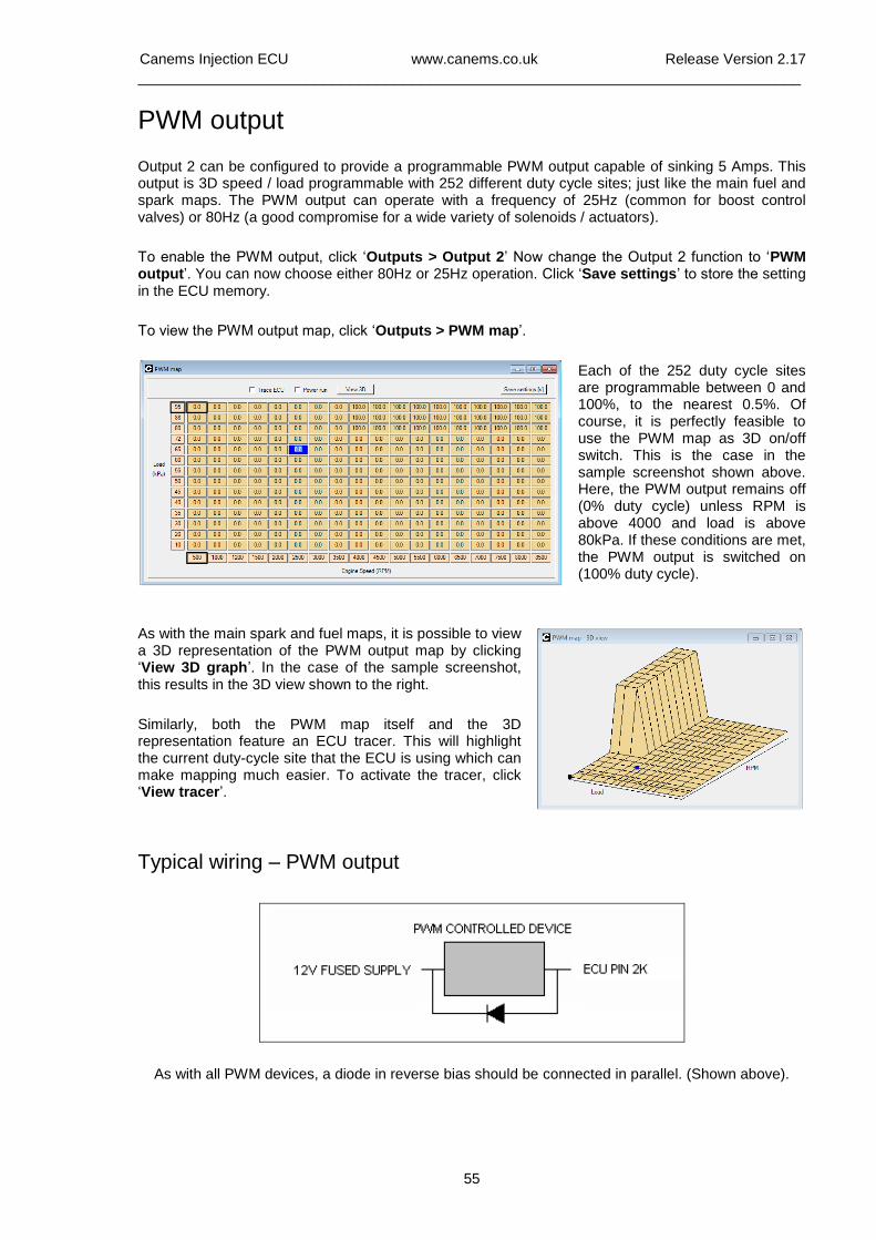
Canems Injection ECU www.canems.co.uk Release Version 2.17
___________________________________________________________________________
55
PWM output
Output 2 can be configured to provide a programmable PWM output capable of sinking 5 Amps. This output is 3D speed / load programmable with 252 different duty cycle sites; just like the main fuel and spark maps. The PWM output can operate with a frequency of 25Hz (common for boost control valves) or 80Hz (a good compromise for a wide variety of solenoids / actuators).
To enable the PWM output, click ‘Outputs > Output 2’ Now change the Output 2 function to ‘PWM output’. You can now choose either 80Hz or 25Hz operation. Click ‘Save settings’ to store the setting in the ECU memory.
To view the PWM output map, click ‘Outputs > PWM map’.
Each of the 252 duty cycle sites are programmable between 0 and 100%, to the nearest 0.5%. Of course, it is perfectly feasible to use the PWM map as 3D on/off switch. This is the case in the sample screenshot shown above. Here, the PWM output remains off (0% duty cycle) unless RPM is above 4000 and load is above 80kPa. If these conditions are met, the PWM output is switched on (100% duty cycle).
As with the main spark and fuel maps, it is possible to view a 3D representation of the PWM output map by clicking ‘View 3D graph’. In the case of the sample screenshot, this results in the 3D view shown to the right.
Similarly, both the PWM map itself and the 3D representation feature an ECU tracer. This will highlight the current duty-cycle site that the ECU is using which can make mapping much easier. To activate the tracer, click ‘View tracer’.
Typical wiring – PWM output
As with all PWM devices, a diode in reverse bias should be connected in parallel. (Shown above).
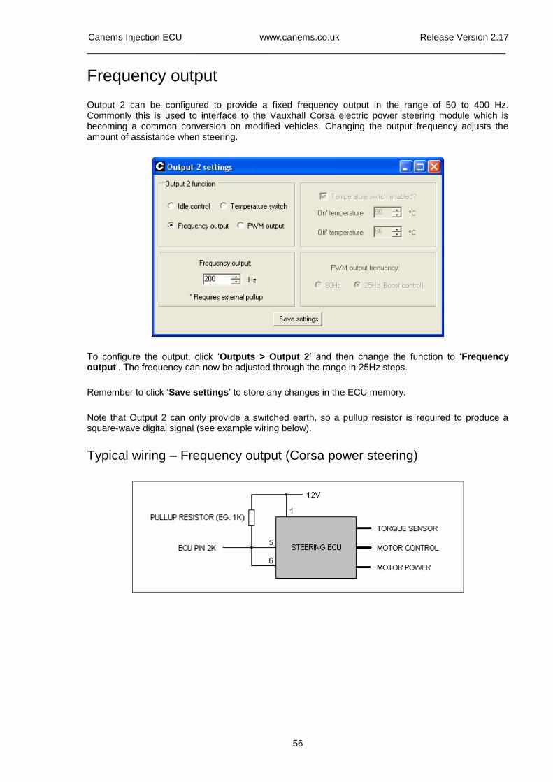
Canems Injection ECU www.canems.co.uk Release Version 2.17
___________________________________________________________________________
56
Frequency output
Output 2 can be configured to provide a fixed frequency output in the range of 50 to 400 Hz. Commonly this is used to interface to the Vauxhall Corsa electric power steering module which is becoming a common conversion on modified vehicles. Changing the output frequency adjusts the amount of assistance when steering.
To configure the output, click ‘Outputs > Output 2’ and then change the function to ‘Frequency output’. The frequency can now be adjusted through the range in 25Hz steps.
Remember to click ‘Save settings’ to store any changes in the ECU memory.
Note that Output 2 can only provide a switched earth, so a pullup resistor is required to produce a square-wave digital signal (see example wiring below).
Typical wiring – Frequency output (Corsa power steering)

Canems Injection ECU www.canems.co.uk Release Version 2.17
___________________________________________________________________________
57
Knock sensing
Available upon request. This input is attached to ECU pin 3E.
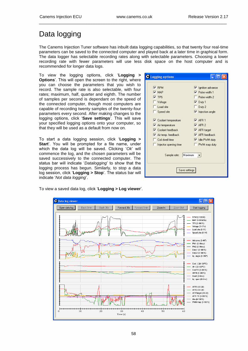
Canems Injection ECU www.canems.co.uk Release Version 2.17
___________________________________________________________________________
58
Data logging
The Canems Injection Tuner software has inbuilt data logging capabilities, so that twenty four real-time parameters can be saved to the connected computer and played back at a later time in graphical form. The data logger has selectable recording rates along with selectable parameters. Choosing a lower recording rate with fewer parameters will use less disk space on the host computer and is recommended for longer data logs.
To view the logging options, click ‘Logging > Options’. This will open the screen to the right, where you can choose the parameters that you wish to record. The sample rate is also selectable, with four rates; maximum, half, quarter and eighth. The number of samples per second is dependant on the speed of the connected computer, though most computers are capable of recording twenty samples of the twenty-four parameters every second. After making changes to the logging options, click ‘Save settings’. This will save your specified logging options onto your computer, so that they will be used as a default from now on.
To start a data logging session, click ‘Logging > Start’. You will be prompted for a file name, under which the data log will be saved. Clicking ‘Ok’ will commence the log, and the chosen parameters will be saved successively to the connected computer. The status bar will indicate ‘Datalogging’ to show that the logging process has begun. Similarly, to stop a data log session, click ‘Logging > Stop’. The status bar will indicate ‘Not data logging’.
To view a saved data log, click ‘Logging > Log viewer’.

Canems Injection ECU www.canems.co.uk Release Version 2.17
___________________________________________________________________________
59
After opening the Log Viewer, click ‘Open data log’ and select the data log file that you wish to view. By default, the Log Viewer shows the first minute of the data log. If the data log is longer than this, the view can be moved forwards by either thirty seconds or five minutes by clicking ‘Forward 30s’ or ‘Forward 5min’, respectively. Similarly, the data log view is moved backwards in time by clicking either ‘Back 30s’ or ‘Back 5min’.
The level of detail in the viewer can also be controlled, so that it is possible to ‘zoom in’ on an area of particular interest. To do this, click ‘Zoom in’ successively. Clicking ‘zoom out’ naturally has the opposite effect.
Data logs from the ECU can be converted to a comma delimited file (.csv) which makes it easy to import the data into third-party analysis software such as Microsoft Excel®. To do this, simply click 'Logging > Export to CSV' clicking on the log file will open your chosen spreadsheet software. You can then build your own charts or even write macros to analyse the performance of your engine.
Digi-dash support & External data logging
The Canems ECU is able to communicate with Race Technology dashboards & data loggers. 21 bytes of data are available from the ECU, including engine RPM, throttle angle, manifold pressure, both air-fuel ratio readings, battery voltage, temperatures etc.
For more information and suitable setup files / data configuration for Race Technology products, please contact Canems or visit the following link location:
http://www.race-technology.com/wiki/index.php/ECUType/CanemsECU
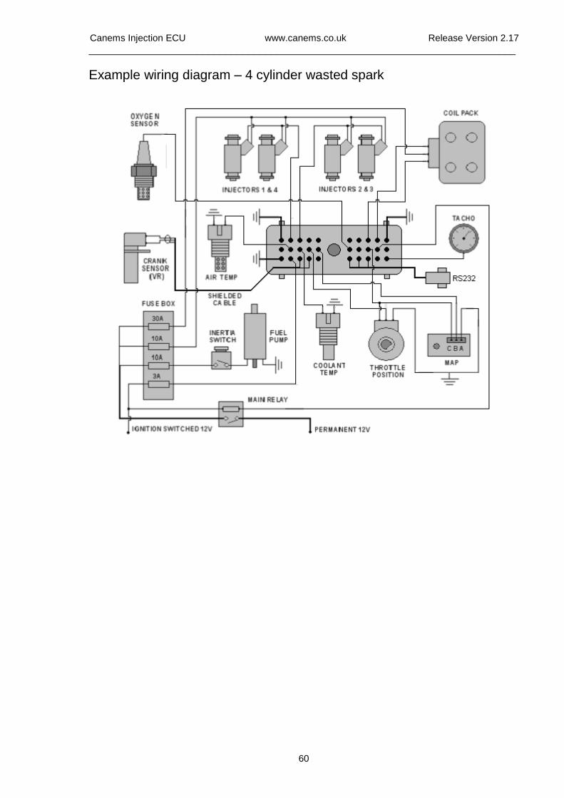
Canems Injection ECU www.canems.co.uk Release Version 2.17
___________________________________________________________________________
60
Example wiring diagram – 4 cylinder wasted spark
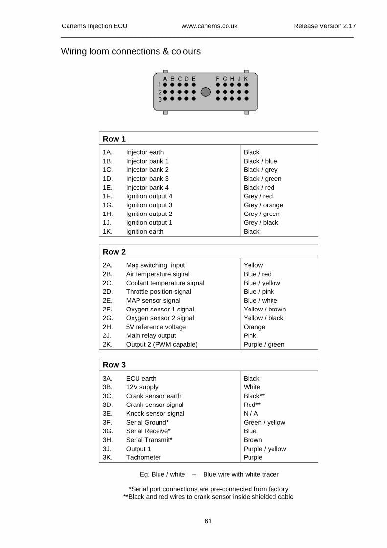
Canems Injection ECU www.canems.co.uk Release Version 2.17
___________________________________________________________________________
61
Wiring loom connections & colours
Row 1
1A. Injector earth
1B. Injector bank 1
1C. Injector bank 2
1D. Injector bank 3
1E. Injector bank 4
1F. Ignition output 4
1G. Ignition output 3
1H. Ignition output 2
1J. Ignition output 1
1K. Ignition earth
Black
Black / blue
Black / grey
Black / green
Black / red
Grey / red
Grey / orange
Grey / green
Grey / black
Black
Row 2
2A. Map switching input
2B. Air temperature signal
2C. Coolant temperature signal
2D. Throttle position signal
2E. MAP sensor signal
2F. Oxygen sensor 1 signal
2G. Oxygen sensor 2 signal
2H. 5V reference voltage
2J. Main relay output
2K. Output 2 (PWM capable)
Yellow
Blue / red
Blue / yellow
Blue / pink
Blue / white
Yellow / brown
Yellow / black
Orange
Pink
Purple / green
Row 3
3A. ECU earth
3B. 12V supply
3C. Crank sensor earth
3D. Crank sensor signal
3E. Knock sensor signal
3F. Serial Ground*
3G. Serial Receive*
3H. Serial Transmit*
3J. Output 1
3K. Tachometer
Black
White
Black**
Red**
N / A
Green / yellow
Blue
Brown
Purple / yellow
Purple
Eg. Blue / white – Blue wire with white tracer
*Serial port connections are pre-connected from factory
**Black and red wires to crank sensor inside shielded cable
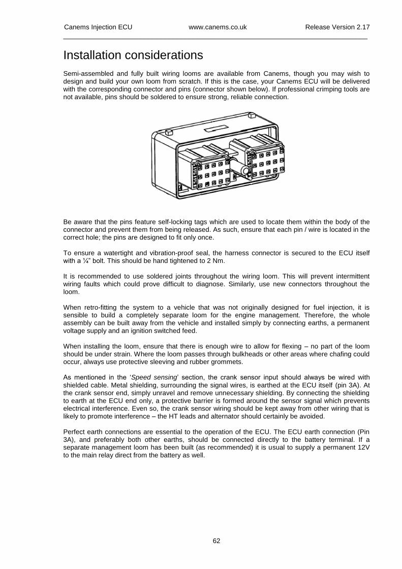
Canems Injection ECU www.canems.co.uk Release Version 2.17
___________________________________________________________________________
62
Installation considerations Semi-assembled and fully built wiring looms are available from Canems, though you may wish to design and build your own loom from scratch. If this is the case, your Canems ECU will be delivered with the corresponding connector and pins (connector shown below). If professional crimping tools are not available, pins should be soldered to ensure strong, reliable connection.
Be aware that the pins feature self-locking tags which are used to locate them within the body of the connector and prevent them from being released. As such, ensure that each pin / wire is located in the correct hole; the pins are designed to fit only once. To ensure a watertight and vibration-proof seal, the harness connector is secured to the ECU itself with a ¼” bolt. This should be hand tightened to 2 Nm. It is recommended to use soldered joints throughout the wiring loom. This will prevent intermittent wiring faults which could prove difficult to diagnose. Similarly, use new connectors throughout the loom. When retro-fitting the system to a vehicle that was not originally designed for fuel injection, it is sensible to build a completely separate loom for the engine management. Therefore, the whole assembly can be built away from the vehicle and installed simply by connecting earths, a permanent voltage supply and an ignition switched feed. When installing the loom, ensure that there is enough wire to allow for flexing – no part of the loom should be under strain. Where the loom passes through bulkheads or other areas where chafing could occur, always use protective sleeving and rubber grommets. As mentioned in the ‘Speed sensing’ section, the crank sensor input should always be wired with shielded cable. Metal shielding, surrounding the signal wires, is earthed at the ECU itself (pin 3A). At the crank sensor end, simply unravel and remove unnecessary shielding. By connecting the shielding to earth at the ECU end only, a protective barrier is formed around the sensor signal which prevents electrical interference. Even so, the crank sensor wiring should be kept away from other wiring that is likely to promote interference – the HT leads and alternator should certainly be avoided. Perfect earth connections are essential to the operation of the ECU. The ECU earth connection (Pin 3A), and preferably both other earths, should be connected directly to the battery terminal. If a separate management loom has been built (as recommended) it is usual to supply a permanent 12V to the main relay direct from the battery as well.
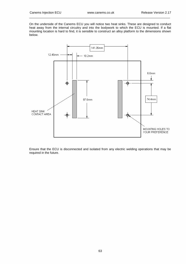
Canems Injection ECU www.canems.co.uk Release Version 2.17
___________________________________________________________________________
63
On the underside of the Canems ECU you will notice two heat sinks. These are designed to conduct heat away from the internal circuitry and into the bodywork to which the ECU is mounted. If a flat mounting location is hard to find, it is sensible to construct an alloy platform to the dimensions shown below.
Ensure that the ECU is disconnected and isolated from any electric welding operations that may be required in the future.
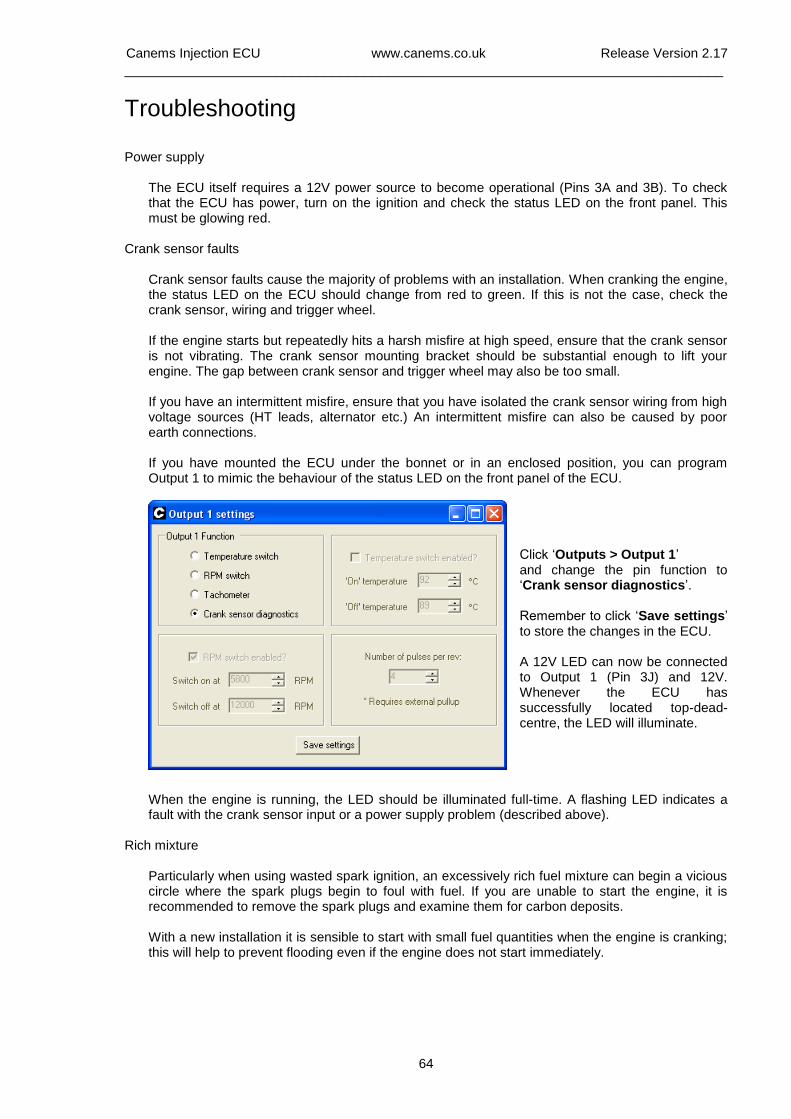
Canems Injection ECU www.canems.co.uk Release Version 2.17
___________________________________________________________________________
64
Troubleshooting Power supply
The ECU itself requires a 12V power source to become operational (Pins 3A and 3B). To check that the ECU has power, turn on the ignition and check the status LED on the front panel. This must be glowing red.
Crank sensor faults
Crank sensor faults cause the majority of problems with an installation. When cranking the engine, the status LED on the ECU should change from red to green. If this is not the case, check the crank sensor, wiring and trigger wheel. If the engine starts but repeatedly hits a harsh misfire at high speed, ensure that the crank sensor is not vibrating. The crank sensor mounting bracket should be substantial enough to lift your engine. The gap between crank sensor and trigger wheel may also be too small. If you have an intermittent misfire, ensure that you have isolated the crank sensor wiring from high voltage sources (HT leads, alternator etc.) An intermittent misfire can also be caused by poor earth connections. If you have mounted the ECU under the bonnet or in an enclosed position, you can program Output 1 to mimic the behaviour of the status LED on the front panel of the ECU.
Click ‘Outputs > Output 1’ and change the pin function to ‘Crank sensor diagnostics’. Remember to click ‘Save settings’ to store the changes in the ECU. A 12V LED can now be connected to Output 1 (Pin 3J) and 12V. Whenever the ECU has successfully located top-dead-centre, the LED will illuminate.
When the engine is running, the LED should be illuminated full-time. A flashing LED indicates a fault with the crank sensor input or a power supply problem (described above).
Rich mixture Particularly when using wasted spark ignition, an excessively rich fuel mixture can begin a vicious circle where the spark plugs begin to foul with fuel. If you are unable to start the engine, it is recommended to remove the spark plugs and examine them for carbon deposits. With a new installation it is sensible to start with small fuel quantities when the engine is cranking; this will help to prevent flooding even if the engine does not start immediately.