Embed Size (px)
Citation preview
!].
%.
L
RMD 5536-F
.... H7o-q._V77
CASE FI L_COPY
VACUUM IGNITION CHARACTERISTICS
OF OXYGEN D_RIDE/DIBORANE
AND FL_TDiBORANE
T,
Thiokol C he-m_-c-aq C o rpo r ation
Reaction Motors Division
Final Rep0rt RMD 5536-F
February 1970
National Aeronautics,_,_a.,_p,_,_SpaceAdministration
Jet Propulsion Laboratory
Pasadena, California

SPECIAL NOTICE
When U. S. Government drawings, specifications, or other data are
used for any purpose other than a definitely related Government procurement
operation, the Government thereby incurs no responsibility nor any obligation
whatsoever, and the fact that the Government may have formulate4, furnished,
or in any way supplied the said drawings, specifications, or other data, is
not to be regarded by implication or otherwise, or in any manner licensing
the holder or any other person Or corporation, or conveying any rights or
permission to manufacture, use, or sell any patented invention that may in
any way be related thereto.
w
RMD 5536-F
VACUUM IGNITION CHARACTERISTICS
OF OXYGEN DIFLUORIDE/DIBORANE
AND FLOX/DIBORANE
T. F. Seamans
-- -i_ I Submitted by:
Approved by:
T. F. SEAMANS
Chief
Combustion and Physics Research
E. EIGER
Director
Research and Engineering
THIOKOL CHEMICAL CORPORATION
Reaction Motors Division
Denville, Nex_ Jersey
RMD 5536-F
FOREWORD
This report is the final report covering work performed by Thiokol
Chemical Corporation, Reaction Motors Division, Denville, New Jersey,
under National Aeronautics and Space Administration Contract NAS 7-660,
Phase II.
The technical manager of the program was Mr. Robert W. Rox_ley,
Liquid Propulsion Section, Jet Propulsion Laboratory, Pasadena,
California 91103. The NASA Project Manager was Dr. Robert S. Levine,
OART, NASA Headquarters, Washington, D. C.
The Phase II technical program described herein was conducted during
the period 15 January 1969 through 14 December 1969. The Phase I
technical program was conducted during the period 15 February 1968 through
15 October 1968 and the results are given in Interim Final Report
RMD 5534-FI, "Vacuum Ignition Characteristics of Flox/Diborane and
Oxygen Difluoride/Diborane", dated March 1969. The Phase Iprogram
stressed-the i_iox/BzH6 propellant combination whereas the Phase n program
stressed the OFz/BzH6 combination.
The Program Manager of the programs was Mr. Thomas F. Seamans
and the Principal Investigator was Mr. George R. Mistier. Other
contributors were Dr. josephine D. Readio and Messrs. B. M. Fagan,
H. W. Romaine and J_ Taylor, Jr.
-=--
U
- ii -
RMD 5536-F
ABSTRACT
The vacuum ignition characteristics of OFz/BzH6, primarily, and
Flox/B2H6 have been investigated in I00 lbf thrust rocket engines to
determine potential problem areas and define design concepts required to
insure reliable vacuum starting of space engines. The engine and
operating parameters investigated were design chamber pressure, dribble
volume/injector configuration, propellant valve type, valve/injector
coupling, run tank ullage, propellant lead/lag, oxidizer temperature, fuel
temperature and hardware temperature. Ignition spikes occurred with the
OFz/BzH 6 combination but only under conditions of an oxidizer lead. No
ignition spikes were observed under any conditions _ith the Flox/BzH6
combination. Cocking of the solenoid valve poppets just prior to the start of
normal poppet transfer allows a low "pre-flow" of the propellants into the
chamber. Initial ignition is very fast and occurs in the vapor phase _hen one
or both of the propellants is in the pre-flow period. Propellant
concentrations, and temperature, are very low. The initial ignition
produces a x_eak flame that acts as a pilot flame for the oncoming bulk flows.
Main ignition occurs when the full mass flow of the lagging propellant occurs.
Combustion residues are formed by both oxidizers with diborane. The
residues contain amorphous elemental boron, HzO and at least two other
components one or both of which are borates though not BzO3 nor H3BO 3.
z
.,o
- 111 -
The reverse of this page is blank.

U
t_
RMD 5536-F
Ig
II.
III.
IV.
Yo
TABLE OF CONTENTS
INTRODUCTION
SUMMARY
EXPERIMENTAL SYSTEM
A. Test Hardware
1. Thrust Chambers
2. Injectors
3. Propellant Valves
a. Valcor Solenoid Valves
b. Conax Explosive Valves
c. Hydraulics Research Bipropellant Valve
4. Valve/Injector Coupling and Dribble Volumes
5. Valve Timing
6. Run Tank Ullage
B. Test System
1. Diborane System
2. Oxidizer System
3. Helium Pressurizing Systems
4. Vacuum Ignition Test Module
5. Temperature Conditioning Systems6. Vacuum/Scrubber System
C. Ins trum entation
RESULTS
A. Ignition Test Results
B. Combustion Residue
DISCUSSION OF RESULTS
A. Effects of the Programmed Variables
I. Effect of Temperature
g. Effect of Propellant Lead/Lag
3. Effect of Valvo/Injector Coupling
Page No.
3
7
8
14
14
17
2O
23
Z5
27
27
31
32
32
34
34
34
37
43
43
43
57
57
57
59
63
- V -
RMD 5536-F
I
VI.
VII.
VIII.
TABLE OF CONTENTS (cont'd)
4. Effect of Run Tank UHage
5. Effect of Injector Configuration
6. Effect of Design Chamber Pressure
7. Bipropellant Valve Tests
8. Explosively Actuated Valve Test
9. OF z- Flox Comparis on
B. Start-Up Processes
C. Problem Areas Encountered
l,
Z.
3.
4.
Oxidizer Valve Freeze-Up
Contamination
Propellant Valves
Post-Ignition Chamber and Manifold POPS
CONCLUSIONS
REC OMMENDA TIONS
REFERENCES
APPENDIX A.
APPENDIX B.
Injector Drax_'ings
Distribution List
1Da g_ e
65
65
66
66
7O
74
76
78
78
79
80
80
83
85
87
A-I
B-1
No:
I
I
B
k • , : Z_
- vi -
RMD 5536-F
Figure No.
4
5
6
7
8
9
10
II
lZ
13
I4
15
16
17
LIST OF FIGURES
Title
Thrust Chamber/Injector Assemblies
Sketch of Propellant Entry Detector Components
and Residue Sampling Probes
Water Flow Check - Valcor Valve and 9 Pair
Doublet Injector
Water Flow" Check - Valcor Valve and 1 Pair
Doublet Injector
Face View" of Injector Assemblies
Back View of an Injector Assembly
Valcor Technical Data for Solenoid Valve
Series 272-C
i
Drawing of Valcor Solenoid Valve Series 272-C
Valve Coil Current and Fuel Manifold Pressurevs. Time
Typical Valve Current Traces
Page 6 of Conax Explosive Valves Bulletin No. 6200
Conax Draw'ing of Explosive Valves P/N 1802-130
Views of Hydraulics Research Valve P/N 48000880
and Connecting Lines
Sketches of Valve/Injector Coupling Configurations
Electrical Lead/Lag Timing of Solenoid PropellantValves
Schematic of Vacuum Ignition Test System for
Phase II Program
Flox System Pressurization Curves
Pa_ e No.
9
I0
11
12
13
13
15
16
18
19
21
22
Z4
26
28
30
33
- Vll -
i
RMD 5536-F
Figure No.
18
19
20
ZI
22
23
24
25
26
27
29
30
3I
32
Title
Vacuum Ignition Test Module
Thrust Chamber Assembly Mounted in Bath
Pressure vs. Altitude
Front View Test Stand S1ZC Installation
IR Spectrum of Black Powder Residue from
OFz/BzH 6 Run 108 (Low Concentration in KBr
Pellet)
IR Spectrum of Black Powder Residue from
OFz/BzH 6 Run 108 (High Concentration in KBr
PelIet)
IR Spectrum of Light Gray Powder Residue from
OFz/BzH 6 Run 108
IR Spectrum of Powder Residue from OFz/BzH sRun I 15
IR Spectrum of Powder Residue from OFz/BzH 6Run 116
IR Spectrum of Air-Exposed, Gray Residue fromOFz/BzH 6 Run 124
IR Spectrum of Powder Residue from Flox/BzH6Run 122.
IR Spectrum of Boron Nitride
Test Hardware following Explosive Valve Failure
Injector and Explosive Valves after Run 78
Explosive Valve Used in Run 78 and New Valve
- viii -
Page No.
35
36
38
39
46
47
48
49
5O
5I
52
54
71
72
73
RMD 5536-F
Table No.
I,
II.
HI.
IV.
V.
VI.
VII.
VIII.
XI.
XII.
LIST OF TABLES
Design Parameters of Hydraulics Research
Bipropellant Valve P/N 48000880
Dribble Volumes of Injector/Valve (Valcor
Solenoid) Combinations
Ullage Volumes of Feed System Configurations
Instrumentation for Vacuum Ignition Tests
Summary of Test Run Conditions
Summary of Test Data
Comparison of "Warm" and "Cold" OFz/BzHs
Ignition Tests
Data Summary of a Test Series Sho_ing Lead/Lag
Effects
Comparison of Oxidizer and Fuel Start-Up Events
Data Summary of OFz/BzH6 Runs Sho_+ing Valve/
Injector Coupling Effects and Run Tank Ullage
Effects
Comparison of Runs Differing in Propellant Valves
Reproducibility of Flox/BzH6 Tests
Page No.
Z3
25
Z9
42
'44
45
58
61
6Z
64
67
75
- ix -

--- RMD 5536-F
= :
F "
I. INTRODUCTION
The high energy propellant combination, oxygen difluoride/diborane,
offers attractive characteristics for improving the mission capability of
future spacecraft. These characteristics (high density, hypergoIic ignition,
excellent performance even at low chamber pressures, and storabIe in space
for extended periods) are especially desirable for high response, lox_ thrust
reaction control system engines for interplanetary missions.
The program described in this report is concerned _ith the vacuum
ignition characteristics of oxygen difluoride/diborane, primarily, and of
Flox/diborane, secondarily. The less expensive 70 percent Fz/30 percent
02 Flox mixture, v_hose overall composition closely matches that of OFz, has
been considered as a substitute for OF 2 in pre-flight hard,'are testing and
evaluation.
The present program is a continuation of the initial study of vacuum
ignition of these propellants conducted in 1968. Reference I is the final
report covering that Phase I effort.
The purpose of the present twelve month technical program is to
further define vacuum starting characteristics and potential problem areas in
vacuum ignition of space engines using oxygen difluoride/diborane and
Flox/diborane propellant combinations.
The program consists of three technical tasks as follows:
TASK I - VACUUM IGNITION OF OFz/B2H 6
The primary effort of the program and of this task _.as an experimental
investigation of the vacuum ignition of 100-1bf thrust rocket engines using the
OFz/BzH 6 propellant combination. The engine and operating parameters
investigated _ere design chamber pressure, dribble volume/injector
configuration, propellant valve type, valve/injector coupling, run tank ullage,
propellant lead/lag, oxidizer temperature, fuel temperature and hardxvare
temperature. A correlative effort to define the physical and chemical
mechanisms _'hich control starting under the test conditions and to define
design concepts and operational procedures required to insure reliable
vacuum starting of OFz/B2H 6 space engines _as performed.
TASK II - INTERCHANGEABILITY OF OFz AND FLOX
This task consists of experimental and analytical studies to determine
the effects on engine ignition characteristics _'hen Flox is substituted for the
OF z. From the tests and supporting analyses, changes in design concepts
- 1 -
RMD 5536-F
and hardware required for reliable starting of space engines when Flox is
substituted for OF z _ere determined.
TASK III - HIGH SPEED MOTION PICTURES
• ' The l_U_lSZ§'e"of this %ask-_._s _to {hx;estigate"te_hniques :{6r taking Use-ful
high speed m0ti0n pictures:of the injection and ignition processes that would
be adequate to aIlom engineering analysis of the physical/chemical processes
involved. Preliminary sketches were prepared to show' thrust chamber
modifications to accept a viewingw'indow. Requirements and procedures toobtain the desired motion pictures w'ere defined.
It was intended at the program outset that the scope of _'ork of this
task would be extended to include the actual taking of the movies. However,
due to a decision during the present program by Corporate management to
phase out the Reaction Motors Division, a program extension to permit
movie-taking was not possible. No further effort was expended in this area.
The results of Tasks I and II of the program are discussed in detail in
the following sections. m!I
-_____
U
B
m
I
w
te-_•
=:z
m
% i
r
!
= _
.,...
RMD 5536-F
II. SUMMARY - " ....
The purpose of the program reported herein _'as to define vacuum
starting characteristics and potential problem areas in vacuum ignition of
space engines using oxygen difluoride/diborane and Flox/diborane as
propellants. :
This report is the final report of a twelve-month program which
consisted of three technical tasks as follo_'s. The primary effort of the
program and of Task lwas an experimental investigation of the Vacuum
ignition characteristics of a I00 Ibf thrust engine using the oxygen difluoride/
diborane propellant combination. The engine and operating parameters
investigated were design chamber pressure, dribble volume/injector
configuration, propellant valve t#pe, valve/injector coupling, run tank
ullage, propellant lead/lag, oxidizer temperature, fuel temperature and
hardware temperature. A correlative effort to define the physical and
chemical mechanisms which control starting under the test conditions and to
define design concepts and operational procedures required to insure reliable
vacuum starting of OFz/BzH s space engines _'as performed.
Task II consisted of experimental and analytical studies to determine
the extent to which results obtained using OF z may be applied to similar
engines using Flox as oxidizer. From the tests and supporting analyses,
changes in design concepts and hardware required for reliable starting of
space engines when Flox is substituted for OF z were determined.
The purpose of Task III was to investigate techniques for taking useful
high speed motion pictures of the injection and ignition processes that would
be adequate to allow engineering analysis of the physical/chemical processes
involved. Requirements and procedures were defined and preliminary
sketches were prepared in anticipation of an increased scope of work which
would provide for the necessary hard, are rework and the actual taking of
the movies. Ho_'ever, due to a decision during the program by Corporate
management to phase out the Reaction Motors Division, a program extension
to permit movie-taking was not possible.
Ignition tests x_.ere conducted with 100-1bf thrust engines at simulated
altitudes in excess of 250,000 ft. The test hardware consists of t_o thrust
chambers; two injectors, three types of propellant valves, tv$0valve/injector
couplings and two run tank ullages. The tw'o thrust chambers differ
primarily in design chamber pressure: I00 psia e/rid 20 psia. Botl_ chambers
have a contraction ratio of 6.25 and an L* of 25 inches.
Two impinging stream injectors were used to evaluate effects of
dribble volume. One injector is a nine element doublet injector
-3-
RMD 5536-F
representative of flight-type hardw'are. The other is a single element
doublet with about one-third the internal volume of the nine pair injector.
Both injectors mate interchangeably with the two thrust chambers.
The bulk of the tests were conducted with light weight, straight
through, solenoid operated, poppet type propellant valves with metal-to-metal
sealing. A few tests were made with a flight-type torque motor operated,
bipropellant valve and with light weight, positive sealing, explosivelyactuated valves.
Two types of valve/injector coupling were tested. In one, the valves
(solenoid) were thermally conditioned with the respective propellant to
assure conditioning of the initially flow'ing propellant to the desired
temperature. Short stand-off tubes with drilled inserts to minimize internal
volumes were used between the propellant valves and the injectors. In the
second configuration, the line lengths were reduced to minimize dribble
volume. In this case the valves were no longer conditioned with the
respective propellant but rather with the injector/chamber.
Primary instrumentation consisted of an optical propellant entry
detector, an optical ignition sensor, and high response, flush mounted
piezoelectric pressure transducers in the thrust chambers and in each
injector manifold. Frequenc_r response _as well in excess of 25 kHz.
Seventy-six vacuum ignition test runs were conducted during this
Phase II program for a total of 124 tests including the Phase I effort. For
the various tests, engine hardware was conditioned to 70 °, 0 °, -I00", -Z00 °
and -Z50°F. Propellant conditioning was as follows: OF z at -170 °, -200 °
and -3Z0°F, Flox at -250 ° and -3Z0°F and BzH s at -10 °, -100 °, -Z00 ° and
-250°F. Propellant lead/lags (electrical) included a range from 13 msecfuel lead to I4 msec oxidizer lead.
With the solenoid propellant valves, the valve poppets cock as the
magnetic flux builds up prior to the start of normal poppet transfer. With the
metal-to-metal sealing, this cocking of the poppets opens small leakage paths
through which propellants pass and then flash vaporize. A very low
"pre-flox_" results which, in the present case, has a duration of 4-8 msec
prior to the start of normal poppet transfer.
Initial ignition is very fast. It apparently occurs in the vapor phase
_'hen one or both of the propellants is in the pre-flow period. Propellant
concentrations at such times are very low as is temperature.
The initial ignition produces a weak pilot flame. The flame then
increases in intensity as the mass input into the thrust chamber increases
provided a reasonable balance betw'een fuel and oxidizer is maintained.
l
I
J
11
I
i$
j
-4-
L
i
= .
z
RMD 5536-F
When the mass input of one propellant lags markedly, the pilot flame
remains weak and "main ignition" is delayed.
Main ignition, or the time _hen significant chamber pressure--and
therefore thrust--begins to develop, occurs when the full mass flow of the
lagging propellant occurs.
Ignition spikes were observed only with OF2 as the oxidizer and, in
these cases, only with an (electrical) oxidizer lead. No ignition spikes wereindicated with fuel leads nor with simultaneous valve signals. With
70/30 Flox as the oxidizer with B2H6, no ignition spikes were observed
under any conditions.
Solid combustion residues were found in the thrust chambers following
each run _ith either OFz/BzH 6 or Flox/B2H6. In selected runs, samples ofthe residues were collected and maintained under an inert atmosphere until
analyzed. In one run, the residue was exposed to air for two days before
being examined. The samples were analyzed by infrared spectroscopy,
X-ray diffraction and flame test. It_as found that similar species are
present in the residues formed by either OF z or Floxwith BzH6. The residues
consist of various concentrations of at least amorphous elemental boron, HzO,
and two other compounds one or both of which are borates (BO3 =, B407=).
Neither H3BO 3 nor BzO3 is present in the residues but BN may be present.
The composition of the residues depends to some extent on the lagging
tail-off propellant.
The factors that promote short delays to main ignition are those
factors that cause rapid, hard-liquid filling of the injector manifolds. These
include flow control by systemAP, high design chamber pressure, small
injector dribble volumes and fast acting propellant valves. Temperature
was found to have no significant effect on delays to main ignition.
The first test with the torque motor operated bipropellant valve ran
normally. Ignition transients with OFz/B2H6 _,ere smooth as expected under
the zero-lead condition. Although the bipropellant valve reached the full
open position more quickly than the solenoid valves under the respective run
conditions, the time to hard liquid filling of the injector manifolds was
slightly longer and therefore the delay to main ignition x_'as also slightly
longer. In the second run, a malfunction occurred in the valve. Following
the run, neither the oxidizer side nor the fuel side sealed properly. The
symptoms and post-run findings are not fully explained.
A test with explosively actuated valves was made with the valves at
below design-point temperatures. Although the fuel-side valve operated
normally, the oxidizer-side valve failed due to reaction of the OFz with the
fuel-rich squib combustion products which blew-by the shear ram into the
do_'nstream cavity of the valve.
-5-
RMD 5536-F
In the midst of the many tests with the solenoid propellant valves, the
oxidizer valve failed to open upon voltage application in tx_,osuccessive runs.
The cause is attributed to a straw-colored material which froze during
temperature conditioning causing the valve to hang up. The material _as
found only in the valve and was insufficient for analysis. After a thorough
cleaning, no further incidents occurred. The nature and origin of the
material is unknown but should be investigated so as to prevent any
recurrence during a space mission.
D
,m
B
i
J
L
--_c._
I
m
m
i":k_̧ _.........
w
r
W
RMD 5536-F
IIl. EXPERIMENTAL SYSTEM
The experimental system for the work reported herein was basicallythe same as that used for the previous study which concentrated on the
Flox/B2H 6 propellant combination (Ref. I). Several improvements to the
system _ere made and additional test hardware was used. For
completeness, a detailed description of the experimental system used in the
present study follows. The experimental system consists of test hardware,
test system and instrumentation system.
A. TEST HARDWARE
The test hard, are includes two thrust chambers, t_o injectors, three
types of propellant valves, two valve/injector couplings and two run tank uliages.
1. Thrust Chambers
Chambers and nozzles were designed for a thrust of 100 lbs under
space conditions. At I00 psia chamber pressure, a Flox/BzS6mixture ratio
of 3 and an exit area ratio of 25, the vacuum specific impulse is approximately
410 sec. The engines were designed for a specific impulse of 400 which
corresponds to a total flowrate of 0.25 lb/sec at an O/F of 3.
To evaluate the expected effect of design chamber pressure on
ignition, two nozzle-chamber combinations were used: one designed for
I00 psia and the second for 20 psia chamber pressure. Each has a
contraction ratio of approximately 6.25 and an L $ of approximately 25 inches.
The nozzles have a 90 degree convergent angle. Throat diameters are
approximately 0.8 and 1.75 in. , respectively. The rounded throat contours
are follomed by only short expansion sections since thrust measurements and
specific impulse were not required. The nozzle flange contains bolt holes
and an O-ring groove to seal to the vacuum system. The upper chamber
flange was designed to hold two Kisiier pressure transducers flush'mounted
in the chamber _all and to bolt to the injector.
For the present study, the two thrust chambers were modified to
accept a "Propellant Entry Detection" system. Each chamber xvas re-worked
at the injector end to mount two small-diameter, interchangeable windows
which are diametrically opposed. One window permits light tO :be beamed
across the injector face. The other permits a light guide to conduct:the
incident light beam to a light detec_or-(see Sec. Hi. C belov_). Propeiiani i
entry is indicated when the beam intensity:is attenuated by passage of thepropellants through the beam,
RMD 5536-F
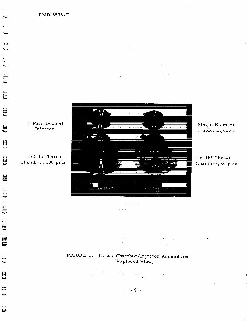
The thrust chambers were also modified to contain probes to
collect condensed-phase combustion residue. Two types of probes were
fabricated. One provides a surface area of .062 square inches and mounts
flush with the chamber wall. The other protrudes 0.8 inches into the
chamber and provides twelve times the surface area.
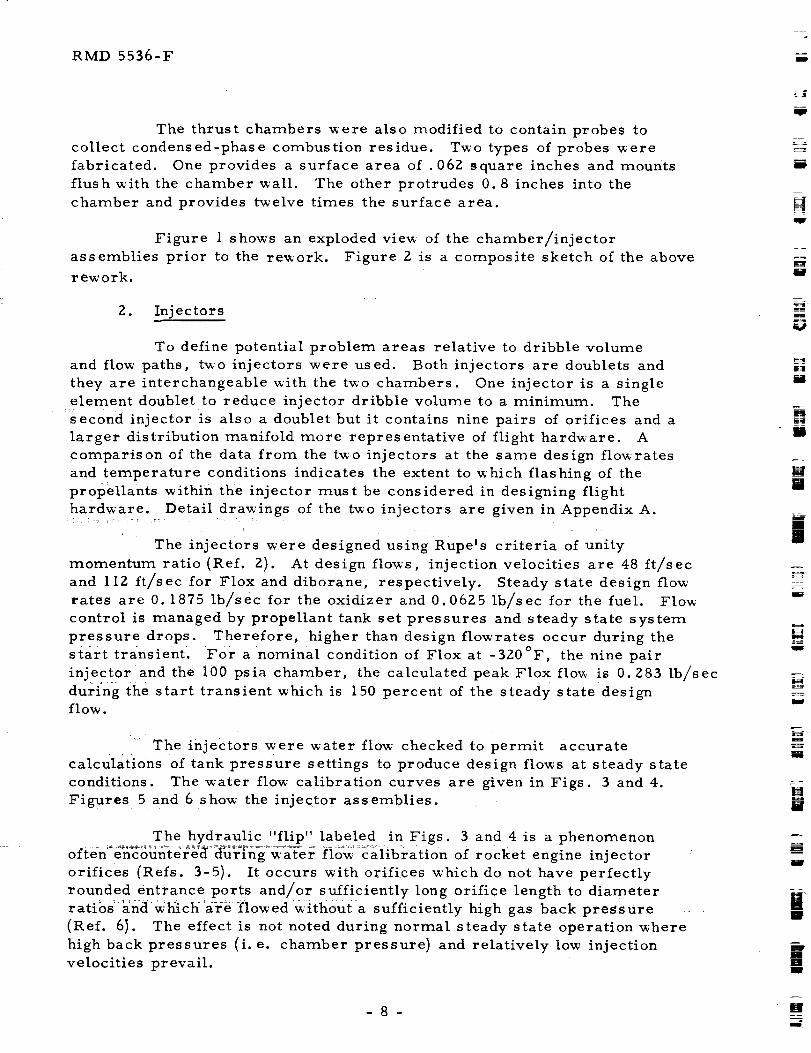
Figure 1 shows an exploded view of the chamber/injector
assemblies prior to the rem ork. Figure 2 is a composite sketch of the above
rework,
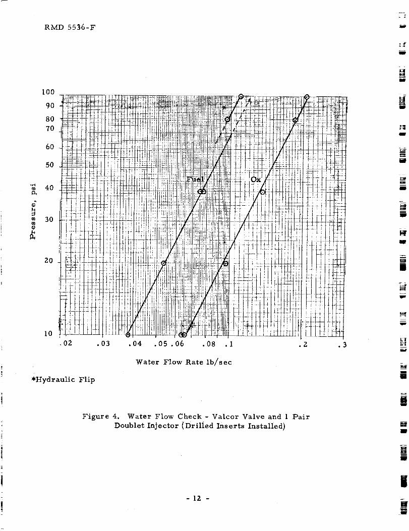
2. Injectors
To define potential problem areas relative to dribble volume
and flow paths, t_'o injectors were used. Both injectors are doublets and
they are interchangeable with the txvo chambers. One injector is a single
element doublet to reduce injector dribble volume to a minimum. The
second injector is also a doublet but it contains nine pairs of orifices and a
larger distribution manifold more representative of flight hardware. A
comparison of the data from the two injectors at the same design flox_rates
and temperature conditions indicates the extent to which flashing of the
Pr0PeHants within the injector must be considered in designing flight
hardware. Detail drawings of the two injectors are given in Appendix A.
The injectors were designed using RupeWs criteria of unity
momentum ratio (Ref. 2). At design flows, injection velocities are 48 ft/sec
and 112 ft/sec for Flox and diborane, respectively. Steady state design flow
rates are 0.1875 lb/sec for the oxidizer and 0.06Z5 lb/sec for the fuel. Flow
control is managed by propellant tank set pressures and steady state system
pressure drops. Therefore, higher than design flowrates occur during the
start transient. For a nominal condition of Flox at -320°F, the nine pair
inject0r and the 100 psia chamber, the calculated peak Flox flo_ is 0.283 lb/sec
during the start transient which is i50 percent of the steady state designflow.
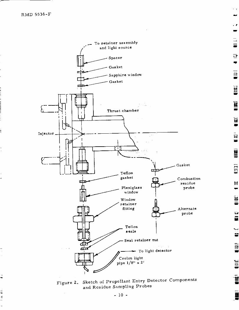
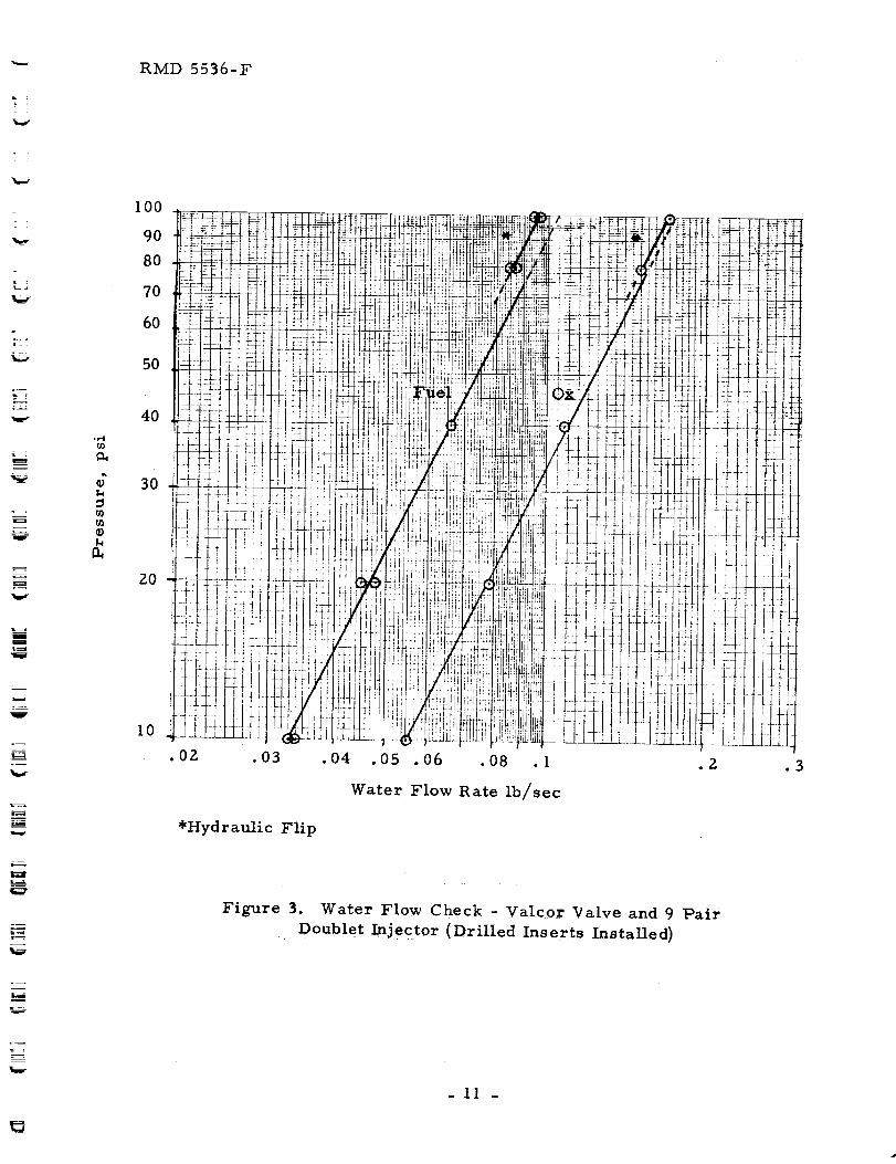
: The injectors were water flow checked to permit accurate
calculations of tank pressure settings to produce design flows at steady state
conditions. The water flow calibration curves are given in Figs. 3 and 4.
Figures 5 and 6 show the injector assemblies.
The hydraulic "flip" labeled in Figs. 3 and 4 is a phenomenon
often=encohntdre_a d_r]_ng+v,'ater fio_ calibration of rocket engine injector
orifices (Refs. 3-5). It occurs with orifices which do not have perfectly
rounded entrance ports and/or sufficiently long orifice length to diameter
ratios anti'which 'are flowed withouta sufficiently high gas back pressure
(Ref. 61 . The effect is not noted during normal steady state operation where
high back pressures (i.e. chamber pressure) and relatively tow injection
velocities prevail.
-8-
m
H
i
[]
m
Im
IMm
RMD 5536-F
9 Pair Doublet
Inj e ctorm Single Element
Doublet Injector
100 lbf Thrust
Chamber, 100 psia
100 Ibf Thrust
i Chamber, 20 psia
FIGURE I. Thrust Chamb_r/Inj e cto r As s emblies
( Exploded Viev,)
....... _ 9
RMD 5536-F
__ To retainer assembly
and light source
Spacer
Gasket
Sapphire x_ indo_'
Gasket
• | ,
T ul t hambe ,nJ.c,or1I _.._ .... \,_ .i ¸
t::.:L_ji ,,_ _o:,,o<
T ,.ou.
Teflon I
: /_- .eal. [
_ _ _Seal retainer nut
I /I_ I I! Crolon light
t '_ 'J pipe l/8"xZ'
Figure 2. Sketch of Propellant Entry Detector Components
and Residue Sampling Probes
- 10
RMD 5536-F
I00
90
8O
70
6O
5O
:_: FI
40 __L:;
30 F;L.4-.
Fq
L 1.. F!
_ ! F-!
LI
10 . _-+
.OZ
• __ ff }*+; -t_+i;-
t +-' [ F ', ;P:
i|! .........-+-_-- _7]:-!
'4 ..... J£[i
! !! Iff! ltil I111
I I I I.
1
...._m::t:i7+ , _ !1ii
-i_f Ui17II t[!i-k tt.... *
•03 .04
Water Flow Rate Ib/sec
*Hydraulic Flip
.3
Figure 3. Water Flow Check- Valcor Valve and 9 Pair
Doublet Injector (Drilled Inserts Installed)
-II
RMD 5536-F
!
oi-I
17}
k
,O2 .1
Water Flow Rate lb/sec
*Hydraulic Flip
Figure 4. Water Flow Check - Valcor Valve and 1 Pair
Doublet Injector (Drilled Inserts Installed)
- 12 -
RMD 5536-F
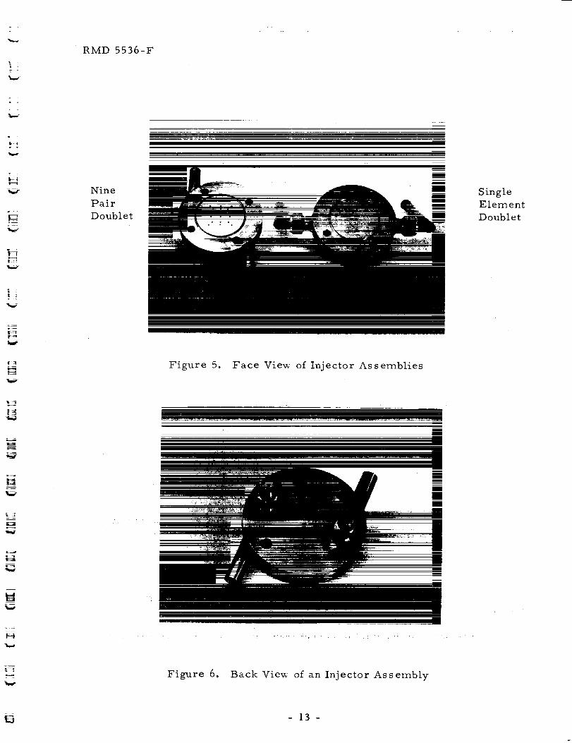
Nine
Pair
Doublet
Figure 5. Face View' of Injector Assemblies
mm
" mm
Single
Element
Doublet
Figure 6. Back View of an Injector Assembly
-13-
RMD 5536-F
Each injector has provisions for flush-mounting high response
Kistler piezoelectric pressure transducers in the fuel and oxidizer injector
manifolds (see injector drawings in Appendix A). Some sealing problems
were encountered during the program in both the fuel and oxidizer sides.
The repeated insertion and removal of the transducers/adapters between the
t_o injectors apparently degraded the 7 mm threads and sealing surfaces to
the point where reliable sealing could not be accomplished. This is notuncommon in situations where lubrication is not permitted and "like" or
"similar" metal threads are in conjunction. To correct the problem, the
7 mm threaded holes in the injectors w'ere enlarged and rethreaded to accept
7/16 x 20 bolts whichhad been re_orked to contain the Kistler pressure
transducers. Deads0ft copper gaskets were provided to seal the bolts in the
injectors. Because Of the construction of the oxidizer manifold, puddled
welding formed part of the sealing surface and minute irregularities
prevented a proper seal. Sealingw'as accomplished when a thin lead gasket
was substituted for the copper. Sealing w'as further improved when the
transducer holder/injector manifold static seals were changed from lead
gaskets to captive teflon sleeves. The teflon seals performed well under
temperature cycling from 70°F to -Z50°F whereas the lead gaskets cold
flowed and leaked.
3. Propellant Valves
Three types of propellant valves were used during the course of
the program: Valcor solenoid valves, Conax explosive valves and a
Hydraulics Research torque-motor bipropellant valve.
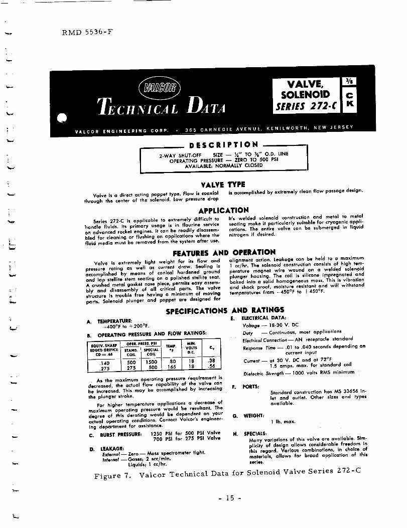
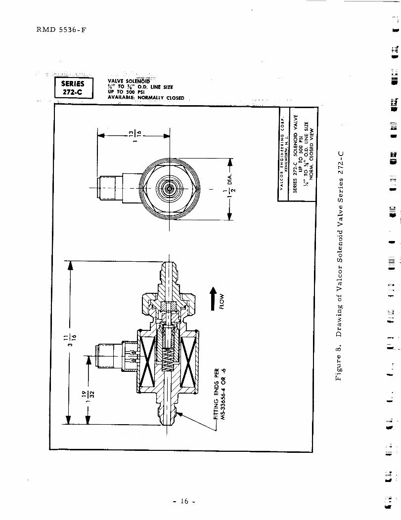
a) Valcor Solenoid Valve
The great majority of tests performed under both phases of
the program used two identical propellant valves manufactured by Valcor
Engineering Corporation and designated P/N V27200-214. These light
w'eight, compact, 1/4-inchvalves are straight-through, solenoid operated,
poppet type valves incorporating steilite seats and stainless steel seals. Thevalves have low' pressure drops and are designed for very corrosive fluids
and for immersion in liquid nitrogen. Figures 7 and 8 give, respectively,
the manufacturer's technical data and a sectional drawing of a typical series
272 valve. '
Typical valve opening times (poppet transfer times)
experienced during the program are 2.5 to 4.5 msec with this period
starting some II-14msec after application of 24 VDC. Generally, evidence
of slight propellant flow' was observed by the injector manifold piezoelectric
transducers prior to the start of poppet transfer. This low flow resulted
from cocking of the valve poppets.
-14-
_- RMD 5536-F
_ 1
DESCRIPTION!
2-WAY SHUT-OFF SIZE -- _" TO _" O.D. LINE J
OPERATING PRESSURE _ ZERO TO 500 PSI IAVAILABLE= NORMALLY CLOSED
VALVE TYPEValve is a direct acting poppet type. Flow |s coaxial is accomplished by extremely clean flow passage design.
through the center of the solenoid. Low pressure drop
APPLICATIONSeries 272-C is applicable to extremely difficult to It's welded solenoid construction and meta) to metal
handle fluids. Its primary usage is in flourine service seating make it particularly suitable for cryogenic appli-on advanced rocket engines. It can be readily disassem- cations. The entire valve can be submerged in liquidbled for cleaning or flushing on applications where the nitrogen if desired.fluid media must be removed from the system after use.
FEATURES AND OPERATIONValve is extremely light weight for its flow and
pressure rating as well as current draw. Sealing Isaccomplished by means of conical hardened groundand lap stellite stem seating on a polished stellite seat.A crushed metal gasket nose piece, permits easy assem-bly and disassembly of all critical parts. The valvestructure is trouble free having a minimum of moving
parts, Solenoid plunger and poppet are designed for
SPECIFICATIONSA. TEMPERATURE:.
--40OAF to + 200°F.
B. OPERATING PRESSURE AND FLOW RATINGS:
EQU/V. SHARP OPEL PRESS. PSi TEMP. MIN,
EDGED ORIFICE STAND. SPECIAL *F VOLTS C v
CD _ .65 COIL COIL D.C.
,140 500 1500 80 t8 .38•275 275 500 165 18 .56
As the maximum operating pressure requirement isdecreased, the actual flow capability of the valve canbe increased. This may be accomplished by increasingthe plunger stroke.
For higher temperature applications a decrease ofmaximum operating pressure would be resultant. Thedegree of this derating would be dependent on youractual operating conditions. Contact Valcar's engineer-
ing department for assistance.
C. BURST PRESSURE: 1250 PSI for 500 PSi Valve700 PSI for 275 PSI Valve
D. LEAKAGE:
External _ Zero -- Mass spectrometer tight.Internal--Gases; 2 scc/mln.
Liquids; 1 co/hr.
Figure 7.
alignment action. Leakage can be held to a maximum1 cc/hr. The solenoid construction consists of high tem-perature magnet wire wound on a welded solenoidplunger housing. The coil is sillcone impregnated andbaked into a solid homogeneous mass. This is vibrationand shock proof, moisture resistant and will withstandtemperatures from --450°F to -I-450°F.
AND RATINGSE. ELECTRICAL DATA:
Voltage -- 18-30 V. DC
Duty -- Continuous, most applications
Electrical Connection--AN receptacle standard
Response Time _ .01 tO .040 seconds depending oncurrent input
Current _ at 30 V. DC and at 72°F
1.5 amps. max. for standard coil
Dielectric Strength_ 1000 volts RMS minimum
F. PORTS:
Standard construction has MS 33656 in-
let and outlet. Other sizes and typesavailable.
G. WEIGHT:
1 lb. max.
H. SPECIALS:
Many variations of this valve are available. Sim-p_icity of design allows considerable freedom Inthis regard. Various combinations, in choice of
materials, allows for broad application of thisseries.
Valcor Technica[ Data for Solenoid Valve Series 272-C
-15-
RMD 5536-F
I SERIES272-C VALVE SOLE_IOID-
_" TO _" O.D. LINE SIZEUP TO 500 PSIAVAILABLE: NORMALLY CLOSED
_N
/
I
C1¢ ',OLU '
_o
z c3LU¢_ .LLI
O_ U_-\.
L)I
r,1
0
@r_
o
,-..1
"U
0
o
O
0o
0
N?
A
o
J
w
z _
I
[]
t
w
I
u
g
I
zt
w
- 16-
._ RMD 5536-F
r •
t
= .
w
z
Ideally, with a new lightly coined metal-to-metal poppet and
seat and proper axial alignment, the sealing line interface is circular. When
the solenoid is energized the coil current starts to build up. At some point
when the magnetic flux is still not great enough to overcome the unbalanced
pressure and spring load forces, the _oppet adjusts radially to the magnetic
field causing the sealing surface to become elliptical. This provides two
small leakage paths shortly before the flux buildup reaches the point where
the poppet starts to transfer axially, lifting off the seat. in the present
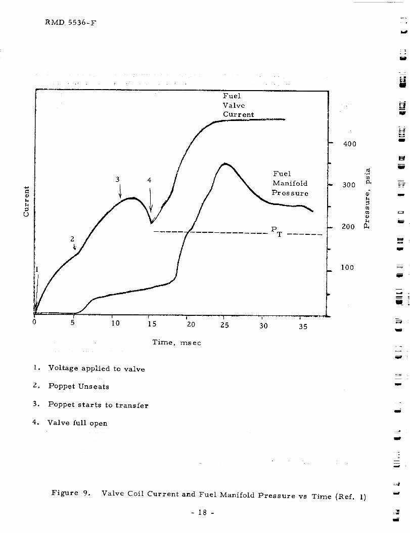
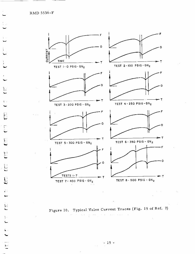
case, poppet cocking generally occurred 6-7 msec after voltage application.
The occurrence of this cocking or radial motion of the poppet prior to valve
opening can be determined from valve current traces such as Fig. 9 (Ref. l)
and Fig. I0 (Ref. 7). However, this phenomenon has been little recognized.
The effect of the cocking with metal-to-metal poppets and seats is transient
leakage, or a slight "pre-flow". The effect with metal-to-plastic or
metal-to-elastomer seals may be absorbed by the elasticity of the materials
with no resultant leakage.
A major problem of valves that rely on metal-to-metal seals
is, of course, leakage which develops or worsens with repeated use. By
Run 59, the leakage rate had become unacceptable and so the valves were
disassembled and examined. The fuel valve poppet was badly scored. The
oxidizer valve poppet was also scored, the seat was etched and the last two
turns of the poppet seating spring were broken. The poppets were refaced
and the seats were lapped. However, the results were not satisfactory as
the fuel valve leaked both gas and liquid. A new poppet was fabricated from
copper in an effort to trade-off operational life for better sealing. The
copper poppet reduced the leakage rate to an acceptable minimal level. The
stainless steel poppet for the oxidizer valve was reworked and performed
properly for a few runs but it too had to be replaced with a copper poppet.
As expected, the operational life of the copper poppets was
considerably shorter than that of the original stainless steel poppets. New
copper poppets were installed in the fuel valve prior to Runs 59, 74, I00 and
I09 and in the oxidizer valve prior to Runs 67, 74, 79, 88, 94, 100 and 109.
In addition as an overhaul, new stellite seat/poppet guide/housing
assemblies and poppet return springs were installed in both valves prior toRun I00.
b) Conax Explosive Valves
Explosively actuated valves (Conax Corporation P/N 1802- 130)
were used in order to determine the effect of zero propellant leakage
(positive sealing) on the starting transient, i.e. in the absence of any
pr e-flow arising from poppet cocking.
-17-
RMD 5536-F
O
[9
3 4
Fuel
Valve
Current
Fuel
Manifold
Pr es sure
2
PT
0 5 10!
15I .......... i .......... I................1 .... =-:
20 25 30 35
Time, msec
1. Voltage applied to valve
Z. Poppet Unseats
3. Poppet starts to transfer
4. Valve full open
400
300
200
100
¢1or-4
0-,
d
m
m
=
J
t-t
I
w
B
m
z
J
= l
J
I
Figure 9. Valve Coil Current and Fuel Manifold Pressure vs Time (Ref. 1)
-18-i
RMD 5536-F
_m,,¢
=
k !E=
_.J
i F
ODIL/" TIME _--T
TEST I- 0 PSIG" GN2
0
T
TEST 3-200 PSIG- GN2
F
0
T
TEST 2-100 PSIG-GN 2
/
¢---T
TEST 4-250 PSIG-GN2
F
0
T
TEST 5-300 PSIG- GN2 TEST 6- 350 PSIG- GN 2
.i-,.
i f
_'0
TEST 7- 400 PSIG- GN2
_--T
TEST 8- 500 PSIG - GN 2
Figure 10. Typical Valve Current Traces (Fig. 19 of Ref.=.=
7)
19-
RMD 5536-F
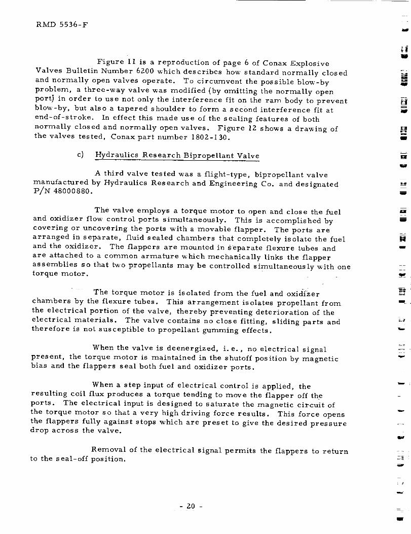
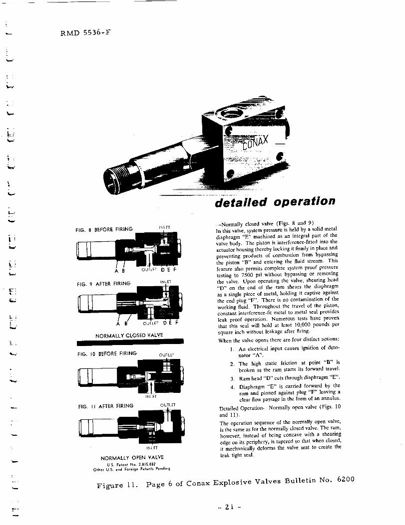
Figure II is a reproduction of page 6 of Conax Explosive
Valves Bulletin Number 6200 _hich describes how standard normally closed
and normally open valves operate. To circumvent the possible blow-by
problem, a three-way valve was modified (by omitting the normally open
port_ in order to use not only the interference fit on the ram body to prevent
blow-by, but also a tapered shoulder to form a second interference fit at
end-of-stroke. In effect this made use of the sealing features of both
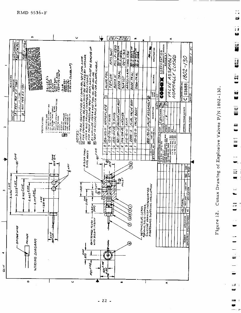
normally closed and normally open valves. Figure 12 shows a drawing of
the valves tested, Conax part number 1802-130.
c) Hydraulics Research Bipropellant Valve
A third valve tested was a flight-type, bipropellant valve
manufactured by Hydraulics Research and Engineering Co. and designated
P/N 4S000S80.
The valve employs a torque motor to open and close the fuel
and oxidizer flow control ports simultaneously. This is accomplished by
covering or uncovering the ports with a movable flapper. The ports are
arranged in separate, fluid sealed chambers that completely isolate the fuel
and the oxidizer. The flappers are mounted in s'eparate flexure tubes and
are attached to a common armature which mechanically links the flapper
assemblies so that two propellants may be controlled simultaneously with one
torque motor.
The torque motor is isolated from the fuel and oxidizer
chambers by the flexure tubes. This arrangement isolates propellant from
the electrical portion of the valve, thereby preventing deterioration of the
electrical materials. The valve contains no close fitting, sliding parts and
therefore is not susceptible to propellant gumming effects.
When the valve is deenergized, i.e., no electrical signal
present, the torque motor is maintained in the shutoff position by magnetic
bias and the flappers seal both fuel and oxidizer ports.
When a step input of electrical control is applied, the
resulting coil flux produces a torque tending to move the flapper off the
ports. The electrical input is designed to saturate the magnetic circuit of
the torque motor so that a very high driving force results. This force opens
the flappers fully against stops which are preset to give the desired pressure
drop across the valve.
Removal of the electrical signal permits the flappers to return
to the seal-off position.
- 20 -
p_
m
[:Jm_zJ
m
_____
U
mJ
zM
g
H
I
m
= =
m
-1:
RMD 5536-F
i rt-_
r
L
i
detailed operation
FIG. g BEFORE FIRING _NLET
A B OUTLET D E F
FIG. c) AFTER FIRING INLET
A OUTLET D E F
NORMALLY CLOSED VALVE
FIG. I0 BEFORE FIRINGOUTLET
iNLET
FIG. II AFTER FIRING OUTLET
)NLET
NORMALLY OPEN VALVE
U.S. Pa+en+ No. 2,81S,882
Ofher U.S. and Foreign Pa'ten'ts Pending
--Normally closed valve (Figs. 8 and 9)
In this valve, system pressure is held by a solid metal
diaphragm "E" machined as an integral part of the
valve body. The piston is interference-fitted into the
actuator housing thereby locking it firmly in place and
preventing products of combustion from bypassing
the piston "B" and entering the fluid stream. This
feature also permits complete system proof pressure
testing to 7500 psi without bypassing or removing
the valve. Upon operating the valve, shearing head
"D" on the end of the ram shears the diaphragm
as a single piece of metal, holding it captive against
the end plug "F". There is no contamination of the
working fluid. Throughout the travel of the piston,
constant interference-fit metal to metal seal provides
leak proof operation. Numerous tests have proven
that this seal will hold at least I0,000 pounds per
square inch without leakage after firing.
When the valve opens there are four distinct actions:
1. An electrical input causes ignition of deto-
nator "A'.
2. The high static friction at point "B" is
broken as the ram starts its forward travel.
3. Ram head "D" cuts through diaphragm "E".
4. Diaphragm "E" is carried forward by the
ram and pinned against plug "F" leaving a
clear flow passage in the form of an annulus.
Detailed Operation--Normally open valve (Figs. 10
and 11).
The operation sequence of the normally open valve,
is the same as for the normally closed valve. The ram,
however, instead of being concave with a shearing
edge on its periphery, is tapered so that when closed,
it mechanically deforms the valve seat to create the
leak tight seal.
Figure 11. Page 6 of Conax Explosive Valves Bulletin No. 6200
..Z1-
RMD 5536-F
og
ooo
Z
,.-4
11)
m
@
NN
O
hi)
N
N
(3
_d
w_
w
I
m
M
I
w
I
Ill_
K_
_W
W
U
L
J
=
- 22 -J
H
= =
r_
_==
RMD 5536-F
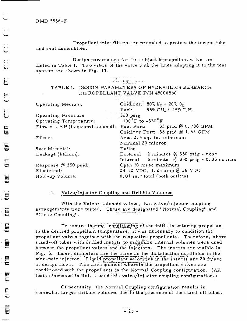
Propellant inlet filters are provided to protect the torque tube
and seat assemblies.
Design parameters for the subject bipropellant valve are
listed in Table I. Two vie_s of the valve with the lines adapting it to the test
system are shown in Fig. 13.
TABLE I. DESIGN PARAMETERS OF HYDRAULICS RESEARCH
BIPROPELLANT VAoLVE P/N 48000880
Operating Medium:
Operating Pressure:
Operating Temperature:
Flow vs. AP (isopropyl alcoholl:
Filter:
Seat Material:
Leakage (helium):
Response @ 350 psid:
Electrical:
Hold-up Volume:
Oxidizer: 80°7oF z + P.0% 0 z
Fuel: 55% CH 4 + 45% CzH6
350 psig+100°F to -320°F
Fuel Port: 32 psid @ 0. 736 GPM
Oxidizer Port: 36 psid @ 1.6Z GPM
Are_2.5 sq. in. minimumNominal Z0 micron
Teflon
External 2 minutes _ 350 psig - none
internal 6 minutes @ 350 psig - 0.36 cc max
Open I0 msec maximum
Z4-32 VDC, I.Z5 amp @ 28 VDC
0.01 in. 3 total (both outlets)
4. Valve/Injector Coupling and Dribble Volumes
With the Valcor solenoid valves, two valve/injector coupling
arrangements were tested. These are designated "Normal Coupling" and
"Close Coupling".
To assure thermal=cond_tion{n-g:of the initially entering propellant
to the desired propellant temperature, it was necessary to condition the
propellant valves together xvith the respective propellants. Therefore, short
stand-off tubes with drilled inserts to mln/mize internal volumes x_'ere used
bet_'een the propellant valves and the injec/_ors. The inserts are visible in
Fig. 6. Insert diameters are the same as the distribution manifolds in the
nine-pair inj ec_0r: : Li:quid_ro-pe-lTant-ve%citi:es :in-:ihe ins:er_s _ are Z0 ft/s ec
at design flows. This arr angeme_w_e)_e]nthe propellant valves are
conditioned with the propellants is the Normal Coupling configuration. (All
tests discussed in Ref. I used this valve/injector coupling configuration.)
Of necessity, the Normal Coupling configuration results insomew'hat larger dribble volumes du_to the presence of the stand-off tubes.
,23 -
RMD 5536-F
I
Q
_k_
u
m
lg
[]J
B
U
Figure 13. Vie_"s of Hydraulics Research Valve P/N 48000880
and Connecting Lines
L_
m
r_
24-J
K_
r=:=_•
RMD 5536-F
To examine this effect, the valve and injectors were reworked to minimize
the line length, yet maintain the capability for interchanging the injectors
and valves. The rework reduced the feed line length by about 49%. This
configuration is the Close Coupling arrangement. An important consequence
is that the valve is no longer conditioned with the propellant but rather with
the injector/chamber.
Sketches of the two valve/injector configurations are given in
Fig. 14.
Dribble volume is defined as the propellant volume between the
downstream side of the closed propellant valve and the downstream face of
the injector. Dribble volumes for the two injectors in each of the two
valve/injector coupling configurations are given in Table II.
TABLE If. DRIBBLE VOLUMES OF INJECTOR/VALVE (VALCOR
SOLENOID) COMBINA TIONS
NORMAL VALVE/INJECTOR COUPLING
CLOSE VALVE/
INJECTOR COUPLING
I-Pair 9 -Pair i-Pair 9- Pair
Injector Injector Injector Injector
cu. in. cu. in. cu. in. cu. in.
Ox Prop to Injector .055
Oxidizer Injector .026
Oxidizer Dribble Volume .081
Fuel Prop to Injector
Fuel Injector
Fuel Dribble Volume
• 064
.031
.095
•055 .029 .029
•083 .026 .083
•138 :'055 .If2
.064 .034 .034
.090 .031 .090
• 154 _ . I2£
5. Valve Timing
With a fixed input voltage, the opening time of a solenoid poppet
valve varies directly with inlet pressure and temperature. The inlet pressure
adds to the force required to open the valve and the temperature changes the
resistivity of the copper coil affecting the energy available to move the
solenoid core. The characteristics of the individual Valcor propellant
valves were such that under the normal inlet pressures and temperatures
(-320°F Oxvalve and -I00°F fuel valve), the valve opening times were
simultaneous with simultaneously applied electrical voltage.
-25-
RMD 5536-F
i
M
I
Vaicor
Propellant
Valves
3.65
Valve
Seat
Location
[]
g
U
U
W
I. 90
(Normal Coupling)
Injector
(Close Coupling)
J
IIW -
Figure 14. Sketches of Valve/Injector Coupling Configurations
-Z6 -
U
•-- RMD 5536-F
IE
_4
_7
In the Phase I program (Ref. I) and in the initial runs of the
present program, a fixed electrical lead x_as obtained x_ith an additional time
delay (nominally ii msec) caused by a relay closure in series _ith the
opposite propellant valve. This method had t_'o shortcomings, however.
First, propellant leads other than thenominal II msec could not be obtained
at a given temperature and, §e60_d, a constant lead could not be obtained at
various temperatureS.
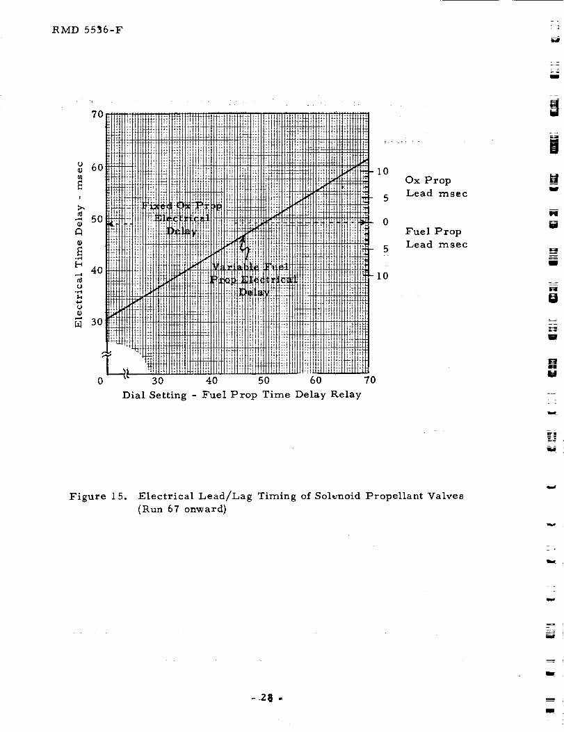
The valve timing system was revised prior to Run 67 to provide a
continuous range of lead/lags. This was accomplished by introducing a fixed
lag in the oxidizer valve circuit and a variable lag in the fuel valve circuit.
Figure 15 gives a plot of time delay relay setting in the fuel valve circuit
versus electrical lead/lag. Figure 15 was used to set a target electrical
lead. The resulting actual electricai lead.as determined from valve
current traces (Sec. III.C).
6. Run Tank Ullage
In the Phase I program, fuel manifold pressures in excess of tank
set pressure _ere indicated under certain conditions (Ref. I, pg. 481 . As
one means for investigation, provisions xvere made to test a second level of
run tank ullage. Specifically, a second pair of run tanks with t_ice the
volume of the first pair were fabricated and fitted to be interchangeable x_ith
the original pair.
In addition, a fuel pre-fill tank _'as added to the fuel system to
permit partial loading of the fuel run tank. Previously, the fuel tank had to
be completely filled for each run and the propellant was fully expelled each
time. (More details of the test system and its operation are given in the
follo_'ing section). Because the run tanks x_'ere small, in order to limit the
quantity of "exposed" propellants in each run, and even though all line
volumes _ere kept as small as practical, the total ullage volumes in the
system_ere•relatively large. Therefore, doubling the run tank volume did
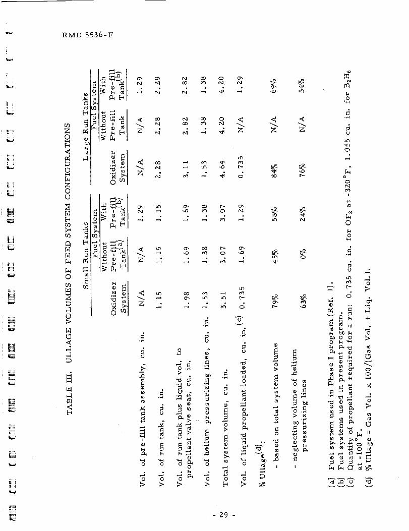
not double the ullage volume. Table ILl summarizes theullage volumes of
the various feed system configurations.
B. TEST SYSTEM
The test system used in the present program is the same one used in
the Phase I program (Ref. I) but with a few additions to improve versatility
and/or reliability. For completeness, a full description of the test systemfollox_ s.
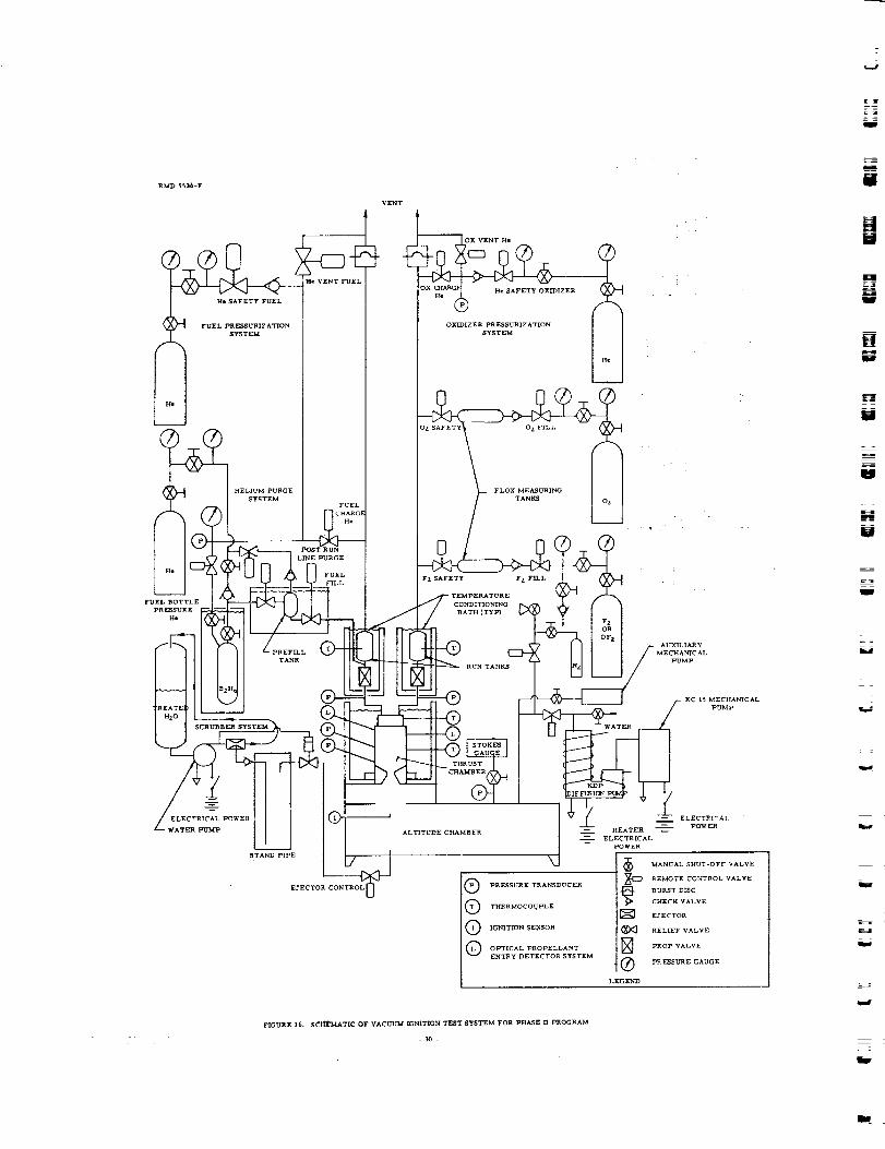
The schematic of the system used in the present program is given in
Fig. 16. The system consists of several subsystems: BzH6 system; Oz, F z
and OF z systems; helium pressurizing systems; temperature conditioning
' Z7 -
RMD 55_6-F
7O
u 60_)
I
•-- 50tl)
.r"l
[.-t40
u
uID
_ 30
=
H I.......
lll?,.iIH_l_÷If÷h,, tttlq_r,H,,f_:,,It_t_dt'_titttt H_÷tHtHttf_tfli_tli_ltl
_IHIItlt,,, _1,ttH,t,,,tttti!titt!t,,,,ttI_,,E Hdt_lttt_,,t_7,_!!__ _ax t _ _t
: _ l 1 J. ill *1
...... _, ,!t t l f < { " II i-i_
,_i_J_ ",<,i 'i ' ' Ni *I _ 'tt r f!li ti!_1
I I i l t _i ' i_ tt I I r I l llh " i' t it Hitti ttj_t_
"_ : . ]illt II = li
iitiilllttl_,,*H,,, i;.,:,,___N_
_1 i ill 1 t i ll£ i 1 _ ttt II
_iltiitti i _ :mititi_i-_iiitfii _iit' i'; Iitit_Hmiitil!Imttit_:lfifffllltittllli H_fnmi_i!,l+t_t+itl i +,i I llll_ifittl l,flHi!l+_
tiiitffl_P_........ t ,.ttHiitit_t
• |t L HlIIIII,,,,,, ,30 4O 50 60
Dial Setting - Fuel Prop Time Delay Relay
10
10
7O
Ox Prop
Lead msec
Fue 1 P rop
Lead msec
N
w
I
l
HHU
u
Figure 15. Electrical Lead/Lag Timing of Solvnoid Propellant Valves
(Run 67 onward)
W
W
- .Z_ .
I _
=
u
r_
RMD 5536-F
O
O
0[D
F_
f4[4
0
[4
0l>
0
,-1,-1
0
o;_1m
oN
0
o_ co t'_ oO o o_eq oo _ tx.1. e_l
Z M M _ 4 Z
tt_
o_ L_ 0 x O0 I_- 0 _
,_ L_ 0_ O0 1_" 0_
'_ ttl O0 0"_
.,-I
o
o
t_
r_
!
o
o
0
*r-_l
U
oo
o ,-_ o
0 0 _'_0 0
0 0 0
u_
u'5 i'--
ov
o
_do
0
o
0
0
b'l
4-:,
0
- 29 -
_-4
o
0
.el
°_,-__ v
o
0
0
cO
t_
1",-
o
0
o
0
0
o
!
u_
2;
o
0
0 o
0 ._
.,-4
o
0
I
0
°r-I
o
u'3
o
0
o
!
I%i
0
0"..t--I
0 "
• _ 0
,._ _>
_ _
b_ _ 0_oo _
o _ oo
"l:J 0 "_0
m _ 0 m
4-_
°ta0
RMD 5$$&-F
CTRI POWER
WATER PU'_P
STAND PIPE
EJECTOR
VENT
__IDOX VENT He• IZER
OXIDIZER PRESSURIZATION
SYSTEM
FLOX MEASURING
TANKS
F Z SAFETT
CONDITIONING
BATH (TYP)
AUXILIARY
MECHANICAL
PUMP
KC 15 MECHANICAL
PUMP
ALTITUDE CHAMBER
Q RESSURE TRANSDUCER
Q THERMOCOUPLE
Q IGb_IT_N SENSOR
Q OPTICAL PROPELLANT
ENTRY DETECTOR SYSTEM
-- ELECTRICAl.
POWER
HEATER
ELECTRICAL
POWER
MANUAL S_JT-OFFVALVE
REMOTE CONTROL VALVE
BURST B_CCHECK VALVE
EJECTOR
_<_ RELIEF VALVE
] PROP VALVE
Q pRESSURE GAUGE
LEGEND
FIGURE 16. SC_I_MATIC OF VACUUM IGNITION TEST SYSTEM FOR PHASE H PROGRAM
- 30 -
= =
l.t
W
!
E
f
L_
L_
=
i
m
L .
RMD 5536-F
systems and a vacuum/scrubber system. Each component_as meticulously
cleaned and degreased prior to assembly. The techniques varied to suit the
individual components and included vapor degreasing, acid baths, solvent
flushing, hot detergent water flushing, rinsing and vacuum drying. Welded or
brazed joints _,ere used wherever possible and Voi-Shan conical flared fitting
seals _ere used with AN flared fitting connectors. Following assembly with
cleaned lines and fittings, the system was leak checked with helium and the
oxidizer subsystem was passivated with fluorine gas.
The test system is described in greater detail in the following
paragraphs.
I. Diborane System
This system provides the proper amount of diborane in the fuel
propellant tank for approximately 200 msec of steady state operation. Such
short runs are sufficient since the study is concerned with events and
processes up to and including ignition but notsteady state operation or
performance. The reasons for limiting the run tank capacity to one run's
worth of propellant were (a) to limit the quantity of "exposed" propellant in
the event of a failure or malfunction, and (b) to simplify overall system
operation especially _hen changing the test hard,'are from one configuration
to another. The original diborane system consisted of (1) a diborane storage
tank with suitable gas side and liquid side hand valves to permit transfer of
the diborane into the test run tank, (Z) a remotely operated cryogenic fuel
fill valve and (3) a run tank and propellant valve.
The original run tank was sized to hold the needed amount of
diborane for a run at 0°F which was the warmest fuel temperature to be
tested. At the much lower temperatures, which constituted the bulk of the
testing, the tank held an excess of diborane since the loading system did not
permit partial loading of the run tank. To provide partial filling, a _pre-fill
tank was added to the system together m ith an additional stop valve and a
pressurizing valve. The pre-fill tank assembly, with a volume of
I. Z87 cu. in. , allows partial filling of either of the diborane run tanks
tested (Table III, Sec. HI.A. 6_.
Each of the three diborane subsystems is maintained at -I00°F
with crushed dry ice in separate conditioning baths (Fig. I6_. Prior to
loading propellant, the system is evacuated from the altitude chamber to the
closed liquid transfer hand valve located onthe diborane storage tank. Thepre-fill tank is then loaded and Subsequently transferred to the run tank.
This technique provides vacuum fill of the diborane up to the propellant
valve seat, thus eliminating trapped gases which could influence start
transients. Follo_'ing each run, the run tank, propellant valve and injector
are purged with helium automatically. Subsequently, the fill lines, pre-fiI1
tank and loading valves are also purged with helium.
-31 -
RMD 5536-F
Z. Oxidizer System
The oxidizer system is used to provide the proper amount of
either liquid OF z or liquid Flox in the oxidizer propellant tank. If Flox is
desired, the 70/30 mixture is made from gaseous fluorine and oxygen. If
OF z is desired, the fluorine cylinder is replaced by a cylinder of OF z and the
O z cylinder is kept closed.
The oxidizer system, then, consists of regulated sources of oxygen
and fluorine (or OFz) gas which are bled into separate measuring tanks
(Fig. 16_. The volumes of the tanks and the lines between the remotely
operated valves are known (F z and OF z system, 138.22 cu. in.; O z system,
62.00 cu. in._. Therefore the desiredw.eights of fluorine and oxygen in the
measuring tanks are readily obtained from the measured gas temperatures
and the set pressures. The run tank and propellant valve are maintained at
-320°F in an insulated conditioning bath filled with liquid nitrogen. Prior to
a run, the prop valve, run tank and oxidizer manifold up to the oxygen and
fluorine safety valves are evacuated. Then, the safety valves are opened
allowing the gases to condense into the run tank. Since the fluorine and
oxygen are condensed into a closed system, the problem of unequal boil-off
changing the Flox percentage composition is avoided. It is expected that the
turbulence caused by the condensation process, natural convection, the high
miscibility of O z and F z and the short time between preparation of the
mixture and firing of the engine (approximately 10 minutes) prevent any
significant stratification of the oxidizer mixture in the run tank. The
operation is monitored by visually observing the measuring tank pressures
on absolute pressure gauges. Because the regulator delivery pressure on
the fluorine bottle is limited, the fill operation is repeated. The t_o
charge/condense cycles provide the proper amount of 70/30 Flox for
Z00 msec of steady state operation. Figure 17 shows the pressure vs
temperature settings required to produce the desired Floxweight in the run
tank. After each run the manifold, run tank and propellant valve are purged
with helium. This system provides the vacuum fill of Flox up to the
propellant valve seat thus eliminating the problem of entrapped gases which
could influence start transients. The same system and methods apply for
OF z except that only the fluorine measuring tank is used.
3. Helium Pressurizing Systems
Separate helium systems pressurize the propellant tanks to the
levels required for steady state desig n flow under the various test conditions.
Helium is used rather than nitrogen because it is less soluble in diborane
(Ref. 8_. Separate systems are used for the oxidizer and fuel tanks to
provide safety through isolation, and flexibility of control. Referring to
Fig. I6, both systems are identical. Each contains a regulated helium
supply, safety valve, charge valve, vent valve and check valve to prevent
back flow into the supply.
m
mr_
g
W
==J
U
m
J
g
w
W
RMD 5536-F
L
6O
.v-I
5O
4O
3O0 ZO 60 80
Temperature OF
Figure 1 7. Flox System Pre ssurization Curves
I00
OZ
FZ
OFz
RMD 5536-F "
A similar arrangement provides the helium required for the purge
of the diborane loading system.
4. Vacuum Ignition Test Module
Most of the comp6ner_ts of the fuel and oxidizer pressurizing
systems, Flox mixing system, the run tanks, propellant valves, and
conditioning baths for the propellant tanks and valves and the diborane
pre-fill tank are mounted on a three foot square by one-half inch thick
aluminum plate. This assembly is called the Vacuum Ignition Test Module.
Figure 18A sho_s a top vie_ of the module in the process of being assembled
for the Phase I program. Figure 18B shox_s a front vie_ of the module _ith
the diborane conditioning bath removed to expose the diborane propellant
tank and solenoid propellant valve.
5. Temperature Conditionin G Systems
The conditioning of the propellants is described in Secs. IIl. B. I
and 2, above, for the fuel and oxidizer, respectively.
The injector/chamber assemblyxYas thermally conditioned to
+70 ° -I00 ° -200 ° and -250°F for the various runs For the -100°F runs
crushed dry ice was placed in the chamber cpndStioning bath and the runs
_ere made after the engine temperatures stabilized at the -100°F dry ice
temperature. The +70°F runs usually required no conditioning since
hard_are temperature in the test stand _as nominally 68°F. For the -Z00 °O
and-250 F runs, advantage x_as taken of the long thermal time constant of
the heavyweight assembly. For these runs, the hard, are
_'as first chilled to -I00 ° _ith dry ice. Additional cooling _'as accomplished
x¥ith liquid nitrogen chilling the dry ice and hardx_'are to about -220° or
-265°F. The engine was fired at -200 ° or -250 ° , as desired, as it warmed
up to restabilize at -I00 °.
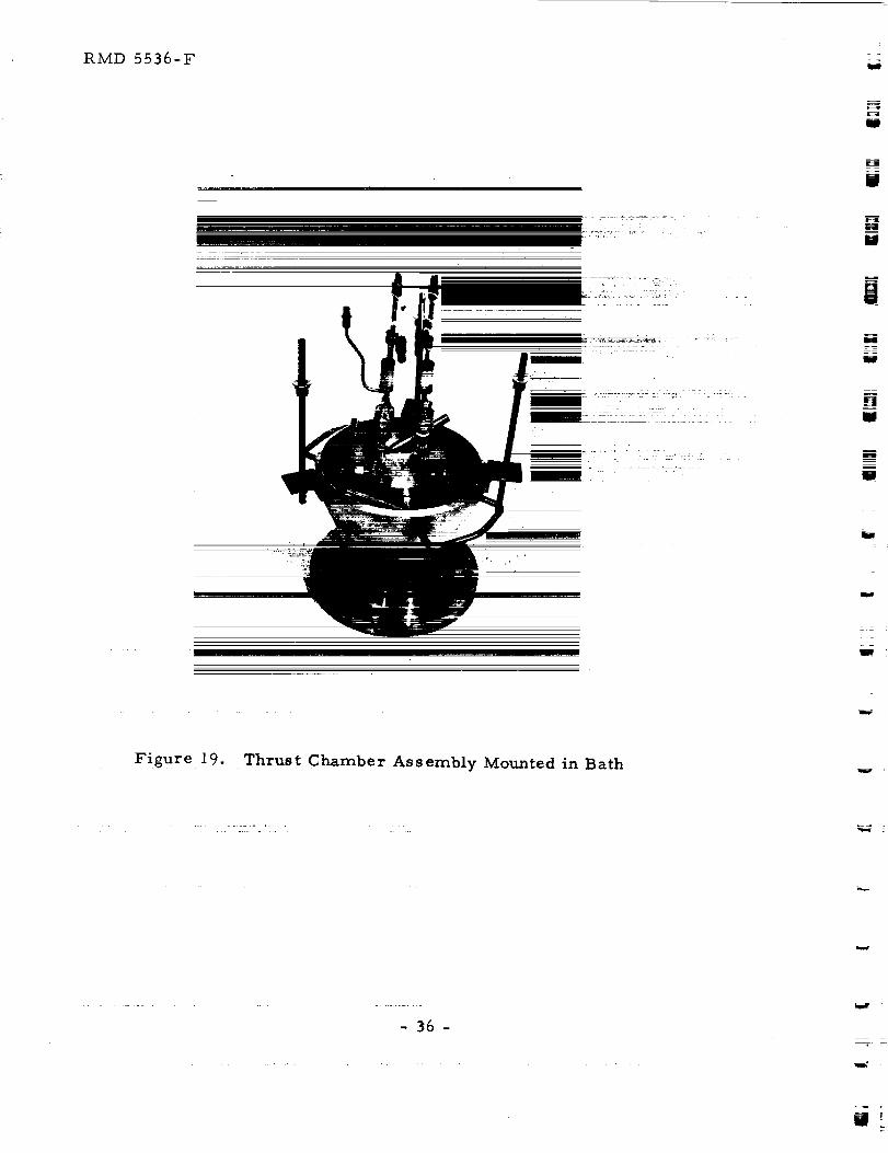
Figure 19 shows the run tanks and solenoid prop valves (decoupled
from the upstream system and without their conditioning baths) connected to
the injector/chamber assembly _hich is mounted in the thrust chamber
conditioning bath. The base flange bolts directly to the altitude simulation
sys tern.
6. Vacuum/Scrubber Sys tern
The vacuum system for the Phase I program x_as designed to
provide an initial pressure altitude in excess of 250,000 ft. It has sufficient
volume to contain the products of combustion of the 0. Z second run plus
1.8 seconds of helium purge at a resulting pressure less than 6 psia.
Calculations sho_ that flo_' is choked in the nozzle throughout the ignition
= =
W
W
g
U
W
-Z
W
%rap :
_4
- 34-
m_
RIVLD 5536-F
L_
i i
_J
L,
.8A. Top Vie_v
18B. Front View
FIGURE 18. Vacuum Ignition Test Module (In Process of Assembly)
- 35-
RMD 5536-F
J
m
!U
WN
m
W
u
w
z
, =
Figure 19. Thrust Chamber Assembly Mounted in Bath
- 36 -
W_
%_.,
--!w-
L
| f
L.4
LJ
L__*
--:r_
RMD 5536-F
delay period and for the duration of the test run. The thrust chamber bath
attaches to a IZ inch length of 8 inch diameter stainless steel pipe x_'hich is
x_,elded to a 5 foot length of I8 inch diameter carbon steel pipe. A 6 inch
Kinney diffusion pump Model KDP-6 is backed by a Kinney mechanical pump
KC-I5. The pumps are isolated from the vacuum chamber during a run by a
4 inch vacuum valve to minimize ingestion of propellant and combustion
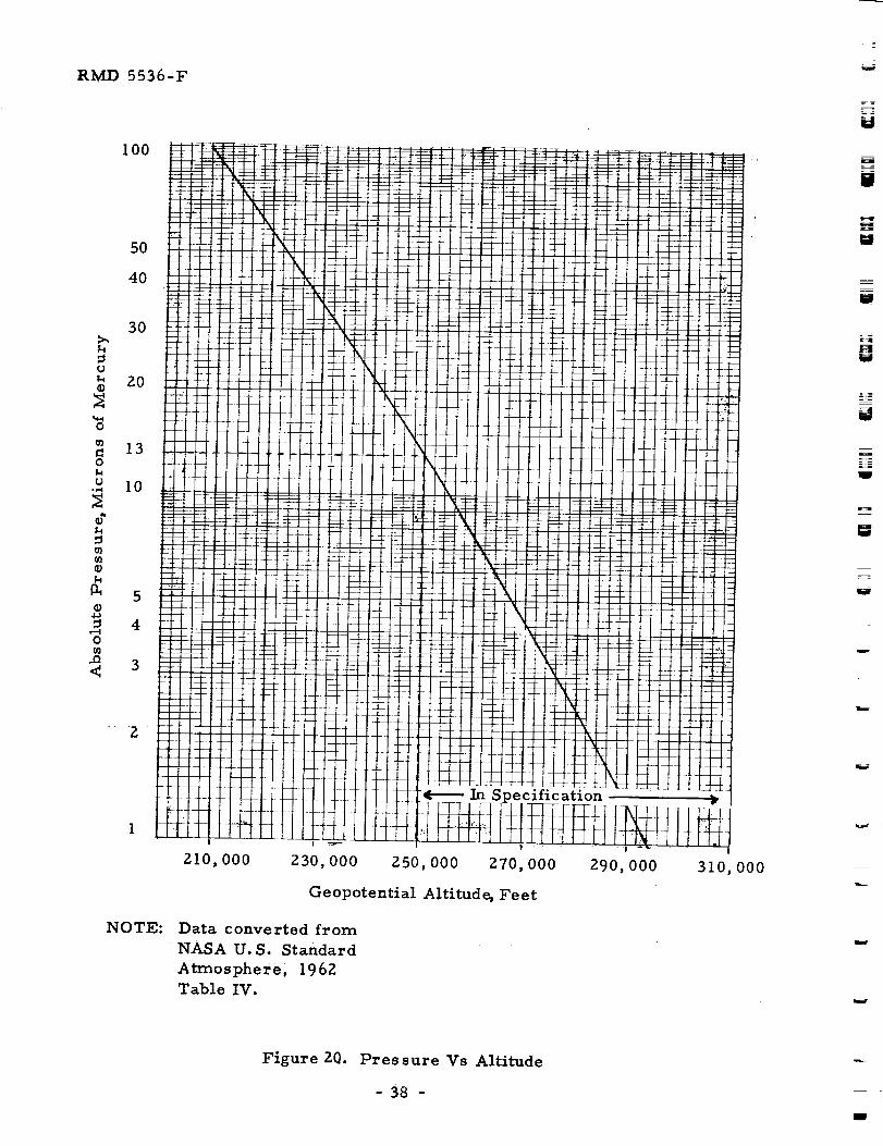
products. The ultimate vacuum attained during test conditions _'as 2 microns
_hich corresponds to a pressure altitude of 282,000 feet. (Figure 20 shox_'s
the relation bet_'een pressure in microns and geopotential altitude in feet.)
Folloxving each altitude ignition test run, the vacuum chamber x_'as
alternately pressurized to 15 psia x_'ith nitrogen and pumped to about 7 psia
by a _'ater ejector system (Fig. 16). Approximately 97 percent of the
gaseous exhaust products _ere removed from the vacuum chamber in this
manner. The gases were entrained in the ejector stream and discharged
into a treated _ater supply. A standpipe and pressure-s_itch-operated stop
valve were added to the scrubber system for the present program to prevent
water back-up into the altitude chamber in the event that the discharge
pressure of the x_'ater pump falls off. Such an incident occurred previously
and resulted in some difficulty in de-contaminating the vacuum facility.
An auxiliary roughing pump was also installed for the present
program to evacuate the altitude chamber before opening the 4-inch vacuum
valve to the KDP-6 diffusion pump and the KC-15 mechanical pump. This
addition _as made to reduce contamination of the high vacuum pumping
system.
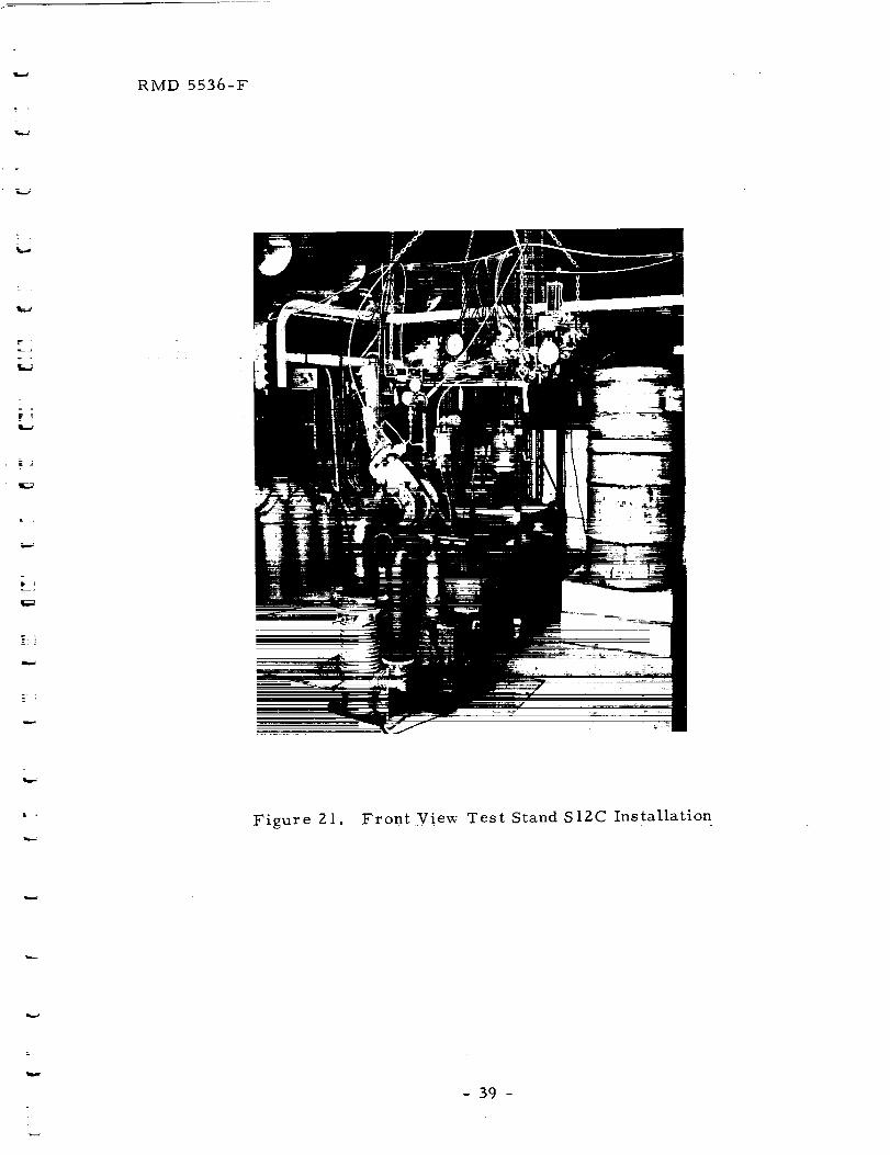
Figure 21 shows a front vie_ of the OFz/BzH 6 altitude ignition test
system installed in Test Stand S12 Bay C during the Phase I program. The
photo shox_s the vacuum ignition test module suspended from an overhead
hoist and supported by four frame posts. The thrust chamber bath assemblyis mounted on the altitude chamber and connected to the module. The
diffusion pump and mechanical pump are in the foreground and the diborane
tank is on the right.
C. INSTRUMENTATION
In addition to conventional instrumentation required for propellant
pressurization and system monitoring, special instrumentationw'as employed
to determine ignition delays and monitor pressure transients during the
ignition delay period. This instrumentation included an optical system to
detect propellant entry into the thrust chamber, a light detector to detect
ignition and high response pressure transducers and recording equipment.
Chamber pressure was measured by two Model 603A Kistler
piezoelectric pressure transducers and t_o Model 566 Kistler charge
- 37-
R_ 5536-F
100
5O
4O
3O>,
o*" 20
0
= 130
u IO-r,,I
0")
_ 5
_ 40
"_ 3<
Z
NOTE:
ZlO, 000 Z30,000 Z50,000 270,000
Geopotential Altitude, Feet
Data converted from
NASA. U.S. Standard
Atmosphere; 1962
Table IV.
290,000 310,000
Figure ZO. Pressure Vs Altitude
- 38 -
l I
ira._̧
RMD 5536-F
Figure 21. Front Vie_* Test Stand S12C Installation
- 39 -
RMD 5536-F
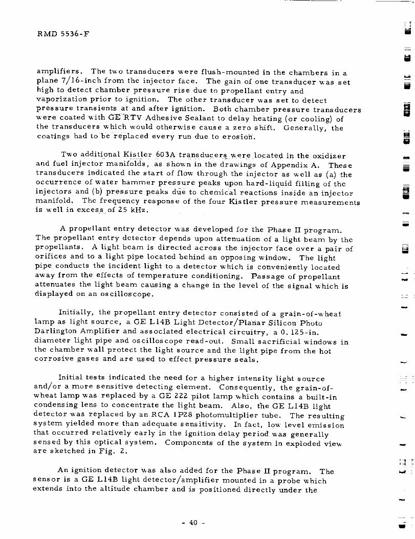
amplifiers. The two transducers were flush-mounted in the chambers in a
plane 7/16-inch from the injector face. The gain of one transducer was set
high to detect chamber pressure rise due to propellant entry and
vaporization prior to ignition. The other transducer was set to detect
pressure transients at and after ignition. Both chamber pressure transducers
x_ere coated with GERTV Adhesive Sealant to delay heating (or cooling) of
the transducers which would otherwise cause a zero shift. Generally, thecoatings had to be replaced every run due to erosion.
Two additional Kistler 603A transducers were located in the oxidizer
and fuel injector manifolds, as shown in the drawings of AppendixA. These
transducers indicated the start of flow through the injector as well as (a) the
occurrence of water hammer pressure peaks upon hard-liquid filling of the
injectors and (b) pressure peaks due to chemical reactions inside an injector
manifold. The frequency response of the four Kistler pressure measurementsis well in excess of Z5 kHz.
A propellant entry detector was developed for the Phase II program.
The propellant entry detector depends upon attenuation of a light beam by the
propellants. A light beam is directed across the injector face over a pair of
orifices and to a light pipe located behind an opposing window. The light
pipe conducts the incident light to a detector which is conveniently located
away from the effects of temperature conditioning. Passage of propellant
attenuates the light beam causing a change in the level of the signal which isdisplayed on an oscilloscope.
Initially, the propellant entry detector consisted of a grain-of-wheat
lamp as light source, a GE L14B Light Detector/Planar Silicon Photo
Darlington Amplifier and associated electrical circuitry, a 0. 1Z5-in.
diameter light pipe and oscilloscope read-out. Small sacrificial _'indows in
the chamber x_all protect the light source and the light pipe from the hot
corrosive gases and are used to effect pressure seals.
Initial tests indicated the need for a higher intensity light source
and/or a more sensitive detecting element. Consequently, the grain-of-
wheat lamp was replaced by a GE 222 pilot lamp which contains a built-in
condensing lens to concentrate the light beam. Also, the GE L14B light
detector was replaced by an RCA 1PZ8 photomultiplier tube. The resultingsystem yielded more than adequate sensitivity. In fact, low level emission
that occurred relatively early in the ignition delay period was generally
sensed by this optical system. Components of the system in exploded vieware sketched in Fig. i.
An ignition detector was also added for the Phase II program. The
sensor is a GE L14B light detector/amplifier mounted in a probe which
extends into the altitude chamber and is positioned directly under the
i
U
m
U
[]N
l
_uW
m
g
g
m
- =
w
RMD 5536-F
! ][ ]
=i ]
m
do_'n-firing rocket engine. The light detector element is protected from the
direct effects of the ignition and combustion by a four inch length of pyrex
glass tubing.
To maintain high response, the signals of the four Kistler transducers
and both optical detectors were displayed on oscilloscopes and recorded
photographically by Polaroid cameras. Fuel manifold pressure, oxidizer
manifold pressure, low sensitivity chamber pressure and propellant entry
_,ere displayed on one Tektronix dual-beam oscilloscope by using two type
C-A plug-in amplifiers _hich permit simultaneous display of four
parameters. High sensitivity chamber pressure, ignition and propellant
entry _'ere displayed on a second Tektronix dual-beam oscilloscope. Joint
display of the propellant entry detector signal provided a common reference
point for both oscilloscope records and eliminated potential errors due to
scope triggering level tolerances. Oscilloscope s_'eep rates _ere
i0 msec/cm up to Run 6Z and 5 msec/cm thereafter. The s_eep_as
triggered by the voltage signal to the leading propellant valve.
Propellant valve voltage and current _ere monitored on a direct print
recording oscillograph. Altitude chamber pressure was measured prior to
each run _'ith a Stokes-McLeod gauge and continuously monitored _ith a
strain gauge transducer and digital read-out. Visual gauges mounted on the
storage gas bottles gave supply and regulated pressures. Separate absolute
pressure visual gauges gave the pressure in each of the two calibrated Flox
and OF z tanks. System temperatures were measured by copper-constantan
thermocouples and monitored _'ith a seven position manual s_'itch and digital
r ead -out.
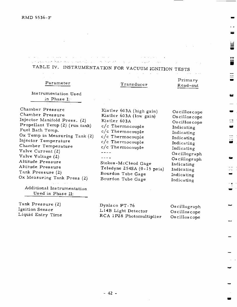
Table IV provides a listing of parameters measured, type of
transducer used and method of read-out. The location of much of the
system monitoring instrumentation is indicated in Fig. 16.
w
- 41 -
RMD 5536-F
l
• _ ".. _ - :: 3-_; : _ '_ " " _ $ " _ • ' - ' ' t " ' '_ "_" " '
TABLE IV. INSTRUMENTATION FOR VACUUM IGNITION TESTS
Primary
Par amete r T rans duc e r Read- out
Instrumentation Used
in Phase I:
Chamber Pressure
Chamber Pressure
Injector Manifold Press. (2)
Propellant Temp (2) (run tank)
Fuel Bath Temp.
Ox Temp in Measuring Tank (2)
Injector Temperature
Chamber Temperature
Valve Current (Z)
Valve Voltage (2)
Altitude Pressure
Altitude Pressure
Tank Pressure (2)
Ox Measuring Tank Press (2)
Additional Ins trumentation
Used in Phase II:
Kistler 603A (high gain)
Kistler 603A (low gain)Kis tler 603A
c/c Thermocouple
c/c Thermocouple
c/c Thermocouple
c/c Thermocouple
c/c The rmocouple
Stokes-McCleod Gage
Teledyne 254SA (0-15 psia)
Bourdon Tube Gage
Bourdon Tube Gage
Oscilloscope
Oscilloscope
Os cillos cope
Indicating
Indicating
Indicating
Indicating
Indicating
Os cillogr aph
Oscillograph
Indicating
Indicating
Indicating
Indicating
Tank Pressure (2)
Ignition Sens or
Liquid Entry Time
Dynis co PT-76
LI4B Light Detector
RCA IP28 Photomultiplier
Oscillograph
Os cillos cope
Os cillos cope
l
m
J
u
g
Z
L_
t_N
w
w
- 4Z -I
RMD 5536-F
%..
L_
IV. RESULTS
A. IGNITION TEST RESULTS
Seventy-six vacuum ignition test runs were conducted during the
Phase II test program (Runs 49-124). Sixty-three of these runs were made
with OFz/BzH 6, five _ith Flox/BzH6, three with OFz alone and five _ith BzH6
alone. All runs were initiated at a pressure altitude in excess of
250,000 feet. Table V is a summary of the test conditions and gives in
addition a remark describing the results of each run.
Detailed data summaries of valve opening times, injector manifold
pressurization events, and the various chamber data are given for
meaningful runs with the solenoid propellant valves in Table VI. Results of
tests using two other types of valves are given and discussed in detail in
Secs. V.A.7 and 8.
B. COMBUSTION RESIDUE
The fact that a combustion residue is for_ned and deposited out is
readily apparent from the propellant entry detector. The transmission of
the windows is decreased 80-90% by the deposit from a single run. For this
reason, the chambers were cleaned before all runs except for those marked
"Nth Start" in Table V. In four OFz/BzH 6 runs and one Flox/BzH 6 run,
samples of the solid material remaining in the thrust chamber were analyzed
by various techniques including infrared, X-ray diffraction and flame test.
The samples analyzed came from OFz/BzH 6 Runs 108, I15, 116 and IZ4 and
Flox/BzH 6 Run 122. With the exception of Run 124, all samples were taken
from a sample plug located in the thrust chamber barrel section two inches
from the face of the injector. The plug extended 0.8 in. into the chamber
and provided an exposed surface area of 0.74 sq. in. After a run, the
sample plug _as maintained in a dry nitrogen atmosphere at all times during
removal from the engine, transfer to the laboratory area, removal of the
sample from the plug and preparation of the sample for the respective
analysis. In the case of Run 124, which was the last of the program, the
engine _as removed from the test system and brought to the laboratory area
_here the hardware remained exposed to air over aweekend. Subsequently,
gray residue was scraped from the face of the 9-pair injector and examined
by infrared spectroscopy, X-ray diffraction and flame test. Only this
Run 124 sample _as subjected to air-exposure.
For the infrared spectra, the samples were mixed with KBr and
formed into a pellet. The spectra are given in Figs. 22 through 28.
- 43 -

llI
mBi
II
iii
m
II
I
I
Jl
nI _
I
hiI
IHI
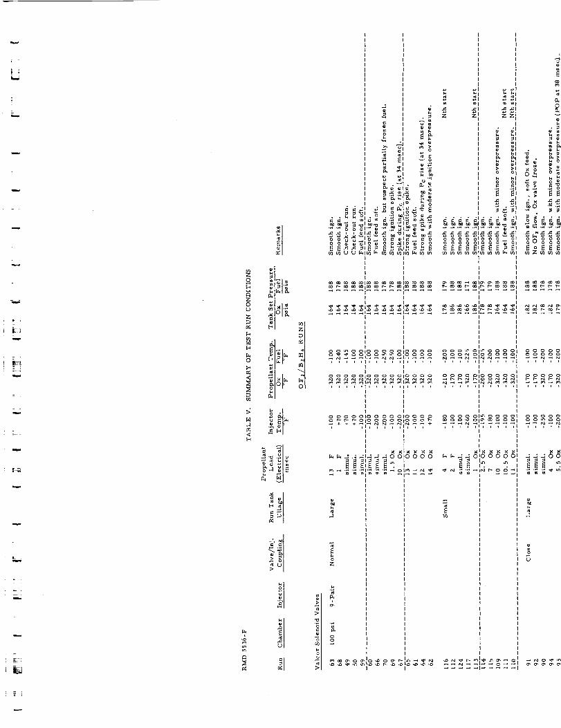
| ;L_
=
_ +w
--+
+
h
U
0
<
<
o,--1
Z
;1
-: _ ._ ._ .._ ._I 0
. _ z _ _z I
_+ .,_ ,._
'_-_ _i _ _ _ "_m _JI _ _ _
_o' ._ . ....... o._ ._ ._ ._ ._ ._ ._1._ ._ ._ _ '_1
, "_11 • _" ._ ._ _ " "1.-_ " _ ._ "'1 -_ e, ._ .-,
_1o _ 01o o0 ol
| I I I
t I l II I I |
| I I I| I I I
I I I II I
, , , I I1, I I , 111 I , I , , + , +1, I I _ ,t , , I I ,I I I II I I I
i l l i ill l l , 11, i , l i i , , i11 l l i ,I l i , l +
I I I I1 1 I I
I I I II I I II I I I
o° o o oolo o_oo o o oo o_ ol o o
l I I II I I I
I I t II I I I
• II • ._: ; _1_ _Ix NI
_I_:_ _'. , _°" ,.,_ _. : __I _ _ _ _ _ _I +o m
,-1 m _1
i :Z
i
°I 0-'.... :l_-" =-+', ....

mm
r_
U
_m
mm
m_mM
Im
zII
L_ul
II
u
u
ibl
W
mm
_LL
iI
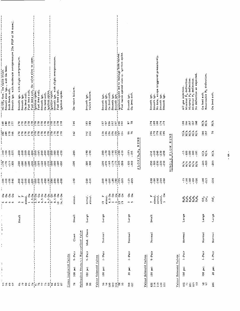
I 0
0 o ,.'_ ooo • _ o-_._=i _o oo,_ °'_I_=,_o_S_ _c_ "_'_ °°_
I II II I
I II |
H:I_{i_ r.- r- r.-.I-- r- r- r_ r- r.- t-- r.- r.-ir_ r.- r-- _-
....... _i_ _r'-_'G-_ r'-
1
°o°o°_ o°°oo°o°°_°._°8°°°o°o°oo o_o
I t
_>°e_° °o°°o°°_,°_°o°°'°o°o°goo-_o-; i t i i t i i i]1 I i i lit I i
I I
I II II I
: I 1O0 0 0 000 0 0100 0 001000 0
oo0-_ ooooo,oo _-_oa o o7.. ..... _,,_, _ _ _ .,_,I I
I I
I I
o,o ; ; ci_'_010;_;
iI
..... _°_>,_0_-_o _- _0_0_o_® _ o__" _" _ _" I I
ooi
ooi
4
oo
6
_. o _
i i
o oo o
oo
,_: ,-:
m
m
p
_-_
. _ .r._ o
Z
I
I X
II
II
I
II
II
oo oo
4 _
h
tlii
_._ ='_, _=I_ _'., _.
0
_T_ z
N
_o
i)
o _ u o
._,_m_,'_ _ '_ o_.._ ®
_:i_ _,_ o
ZZZZZ --
,,,, ZZ Z
ZZZZZ , ,
.... _ 7g ff
__ oo o
J J
Z Z Z
•_, -_
u
_u _u

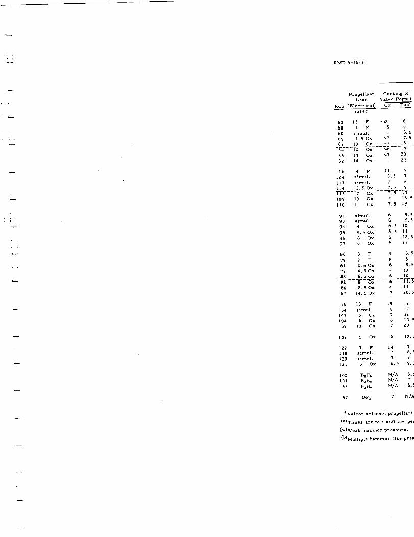
RMD 5536-F
o
l
Propellant Cocking of
Lead
Run (Electrical) Ox Fuel
ms ec
63 13 F _Z0 6
68 I F 8 6
60 s imul. 6. 5
69 I. 50x _7 7. 5
67 I0 Ox _7 16
-_%--- Fz--7_'_---'_---i-9--"65 13 Ox _7 Z0
6Z 14 Ox - Z3
116 4 F II 7
IZ4 s imul. 6. 5 7
117 simul. 7 6
114 Z.5Ox 7.5 9
I 15 7 Ox 7.5 [3-'-"
109 l0 Ox 7 16. 5
II0 II Ox 7.5 19
91 s irnul. 6 5. 5
90 simul. 6 5. 5
94 4 Ox 6. 5 I0
95 5.5Ox 6.5 II
96 6 Ox 6 1Z. 5
97 6 Ox 6 I 3
86 3 F 9 5. 5
79 Z F 8 6
81 Z.5Ox 6 8.5
77 4. 50x I0
88 6.50x 6 lZ
8-2- 8 Ox g---[f_
84 8.50x 6 14
87 14.50x 7 20.5
56 13 F 19 7
54 sirnul. 8 7
103 5 Ox 7 IZ
I04 6 Ox 8 13. 5
58 13 Ox 7 ZO
108 5 Ox 6 10, =-
IZZ 7 F 14 7
118 s imul. 7 6. c
120 simul. 7 7
121 3 Ox 6.5 9.. E
I02 BzH6 N/A 6. !
I01 BzH6 N/A 7
53 B,H6 N/A 6. !
57 OFz 7
*Valcor solenoid propellant
(a)Times are to a soft low pe_
(W)Weak hammer pressure.
(h) Multiple hammer-like pres

i
M
i
m
M
I
NN
m
m
J
m
i
L_
mm
i
m
mm
----m----mm
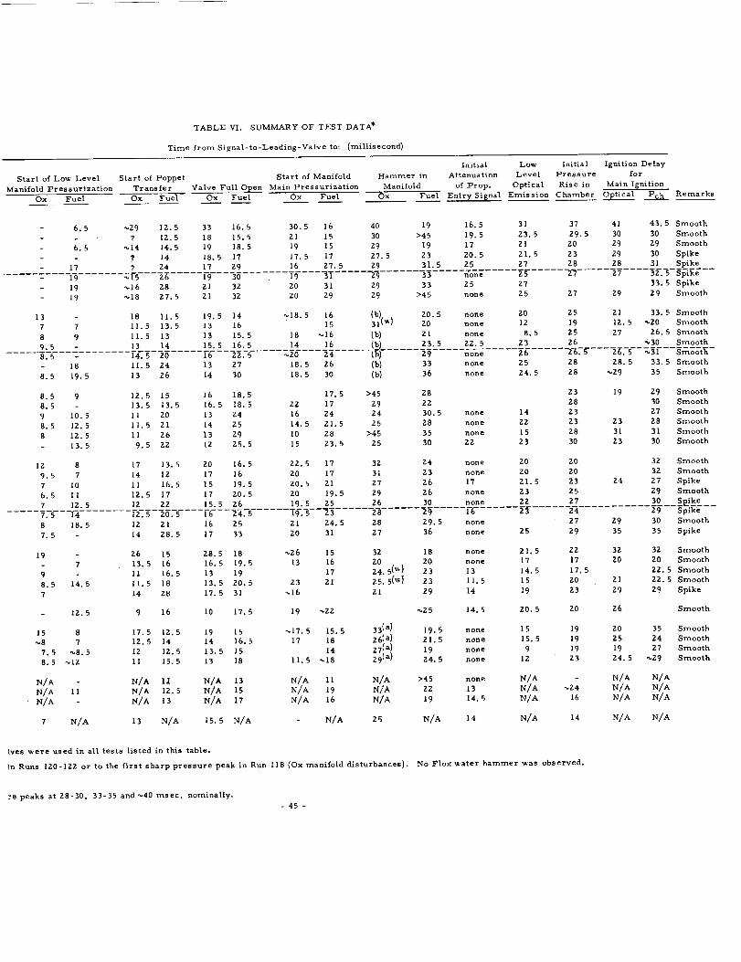
TABLE VI. SUMMARY OF TEST DATA*
Time from Signal-to-Leading-Valve to: (millisecond)
Start of Loxv Level Start of Poppet Start of Manifold
Manifold Pressurization Transfer Valve Full Open Main Pressurization
Ox Fuel Ox Fuel Ox Fuel Ox Fuel
Initial Lo_w Initial
Hammer in Attenuation Level Pressure
Manifold of Prop. Optical Rise in
Ox Fuel Entry Signal Emission Chamber
6.5 _29 12.5 33 16.5 30.5 16 40 19 16.5 31 37
- _ ? 12.5 18 15.5 2t 15 30 >45 19.5 23.5 29.5
6.5 _14 14.5 19 18.5 19 15 29 19 17 21 20
? 14 18.5 17 17.5 t7 27.5 23 20.5 21.5 23
17 ? 24 17 29 16 27.5 29 31.5 25 27 28
19 _15 2_ 19 30 19 31 29 33 none 25 27
Ignition Delay
for
Main Ignition
Optical Pch Remarks
41 43.5 Smooth
30 30 Smooth
29 29 Smooth
29 30 Spike
28 31 Spike
27 32.5 Spike
13
7
8
9.5
19 _16 28 21 32 20 31 29 33 25 27
19 _18 27.5 21 32 20 29 29 >45 none 25 27 29
18 11.5 19.5 14 _18.5 16 (b) 20.5 none 20 25 21
7 11.5 13.5 13 16 15 31 (_) 20 none 12 19 12.5
9 11.5 13 13 15.5 18 _16 (b) 21 none 8.5 25 27
13 14 15.5 16.5 14 16 (b) 23.5 22.5 23 26
8.5 14.5 20 16 22.5 _20 24 ]g_ ..... _ ..... _o_g ..... 2ff ..... -2_7_---_. 5
- 18 11.5 24 13 27 18.5 26 (_ 33 none 25 28 28.5
8.5 19.5 13 26 14 30 18.5 30 (_ 36 none 24.5 28 _29
8.5 9 12.5 15 16 18.5 17.5 >45 28 23 19
8.5 13.5 13.5 16.5 18.5 22 17 29 22 28
9 10.5 11 20 13 24 16 24 24 30,5 none 14 23
8,5 12.5 11.5 21 14 25 14.5 21.5 25 28 none 22 23 23
8 12.5 11 26 13 29 10 28 >45 35 none 15 28 31
13.5 9.5 22 12 25.5 15 23.5 25 30 22 23 30 23
12 8 17 13.5 20 16.5 22.5 17 32 24 none 20 20
9,5 7 14 12 17 16 20 17 31 23 none 20 20
7 I0 11 16.5 15 19.5 20.5 21 27 26 17 21.5 23 24
6.5 II 12.5 17 17 20.5 20 19.5 29 26 none 23 25
7 12.5 12 22 15.5 26 19.5 25 26 30 none 22 27
7.5 14 12.5 20.5 16 24.5 _% 5 23 28 29 _ 23 24
8 18.5 12 21 16 25 21 24.5 28 29.5 none 27 29
7.5 14 28.5 17 33 20 31 27 36 none 25 29 35
19 26 15 28.5 18 _26 15 32 18 none 21.5 22 32
- 7 13.5 16 16.5 19.5 13 16 20 20 none 17 17 20
9 II 16.5 13 19 17 24.5 (_) 23 13 14.5 17.5
8.5 14.5 11.5 18 13.5 20.5 23 21 25.5( W} 23 11.5 15 20 21
7 14 28 17.5 31 _16 2t 29 14 19 23 29
- 12.5 9 16 10 17.5 19 _22 _25 14.5 20.5 20 Z6
15 8 17.5 12.5 19 15 _17,5 15.5 33 (_ 19.5 none 15 19 20
_8 7 12.5 14 14 16.5 17 18 26(a) 21.5 none 15.5 19 25
7.5 _8.5 I2 12.5 13.5 15 14 27 (a) 19 none 9 19 19
8.5 _12 11 15.5 13 18 11.5 _18 29 (a) 24.5 none 12 23 24.5
N/A - N/A I: N/A 13 N/A 11 N/A >45 none N/A - N/A
N/A II N/A 12.5 N/A 15 N/A 19 N/A 22 13 N/A _24 N/A
N/A - N/A 13 N/A 17 N/A 16 N/A 19 14.5 N/A 16 N/A
7 N/A 13 N/A 15.5 N/A N/A 25 N/A 14 N/A 14 N/A
Ires _.ere used in all tests listed in this table,
in Runs 120-122 or to the first sharp pressure peak in Run 118 (Oxmanifold disturbances}, No Flox_ater hammer _'as observed.
33. 5 Spike29 Smooth
33.5 Smooth
"_20 Smooth
26.5 Smooth
"_30 Smooth
"_31 Smooth
33.5 Smooth
35 Smooth
Z9 Smooth
30 Smooth
27 Smooth
28 Smooth
31 Smooth
30 Smooth
3Z Smooth
32 Smooth
27 Spike29 Smooth
30 Se_k_ __29 Spike30 Smooth
35 Spike
32 Smooth
20 Smooth
22.5 Smooth
22.5 Smooth
29 Spike
Smooth
35 Smooth
24 Smooth
27 Smooth
_29 Smooth
N/A
N/A
N/A
N/A
:e peaks at 28-30, 33-35 ands40 msec, nominally.
- 45 -

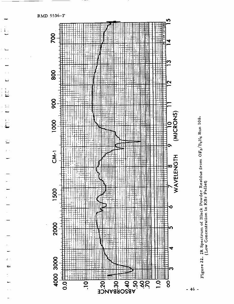
r
j -
RAiD 5536-F
OO
OO00
OOO
U
OOO O
O
O
m
CO
O O_ oooo o II3_'NV_OS_V'
OrwU
V
o
N
O
- 46 -
ok
m._0
u
_u
,4
°_,_

/N
mmm'
W
•W i
mira
n
f
f
d
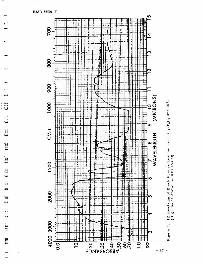
RMD 5536-F
i
F
w
_4
w
= =
m
00D,,
00O0
00O_
OOO
O0
000O4
000
000-e o o
O '--
u_
Z0
_do
0
0
o_
_._
U0
m_0 ._
_ 0
d
47-
I.l
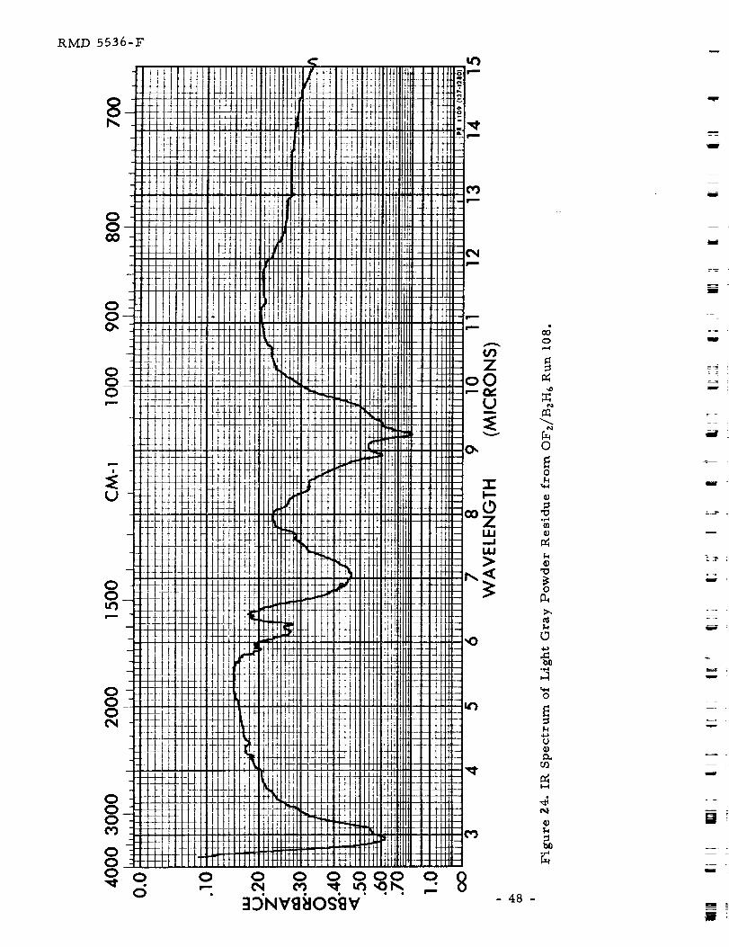
RMD 5536-F
I
=_
u
T
3 'NW OSgV
O
m,=l
2N
O
o
°m,l
¢)
OD.
t_
.p,l
O
I-I
u¢)
D_
I.,-I
e_
¢)
l
m
m
i
= =
i
i ;
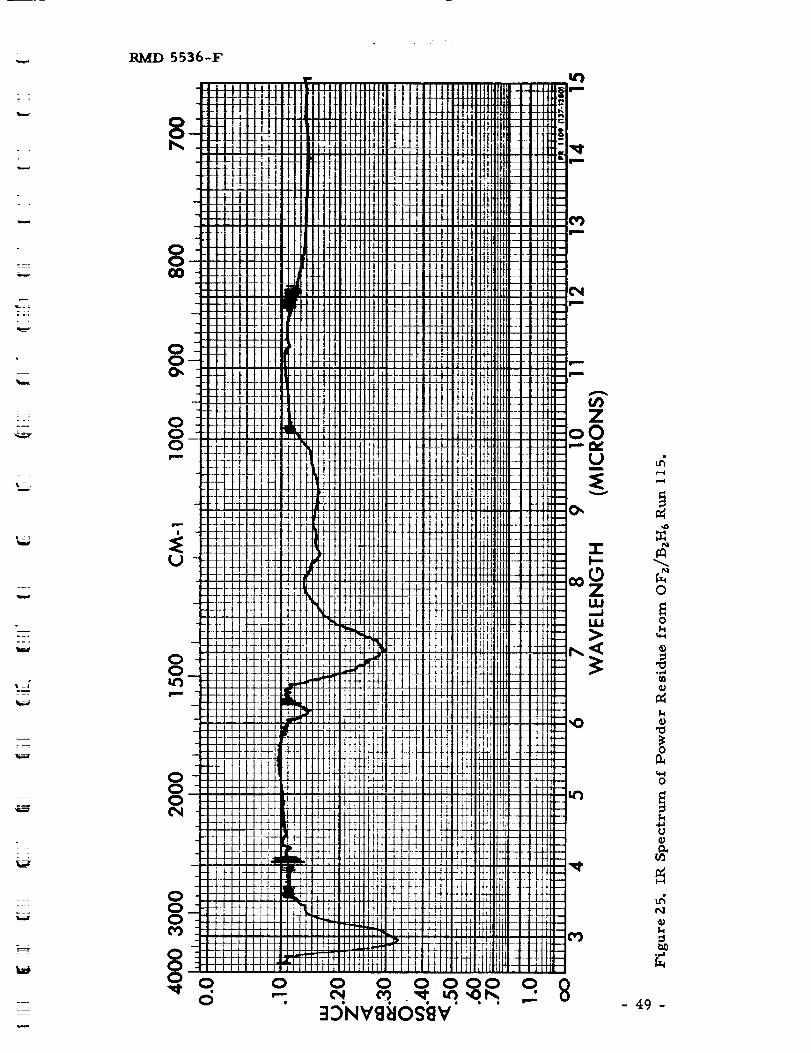
=
.=.
T_
===
w
L_
=:
w_
w
RIVtD 5536-F
OOO,
000
00
o0O o
.o
oI""
O Oew (_)
w,)
From
('Wm
l
U9Z
oO,--iv
L)m
:Ev
-rF-
_OZU.l
u.l>
,O
_4,"4
N
N
O
Ok
W
n:J
o
o
u
(n
N
b_
- 49 -
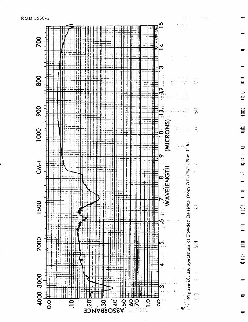
RMD 5536-F
OO
OO
OO
OOO
U
OO
000
000
000 0,_. .
0.
I
i
= =
w
m
w
_ °
m
m
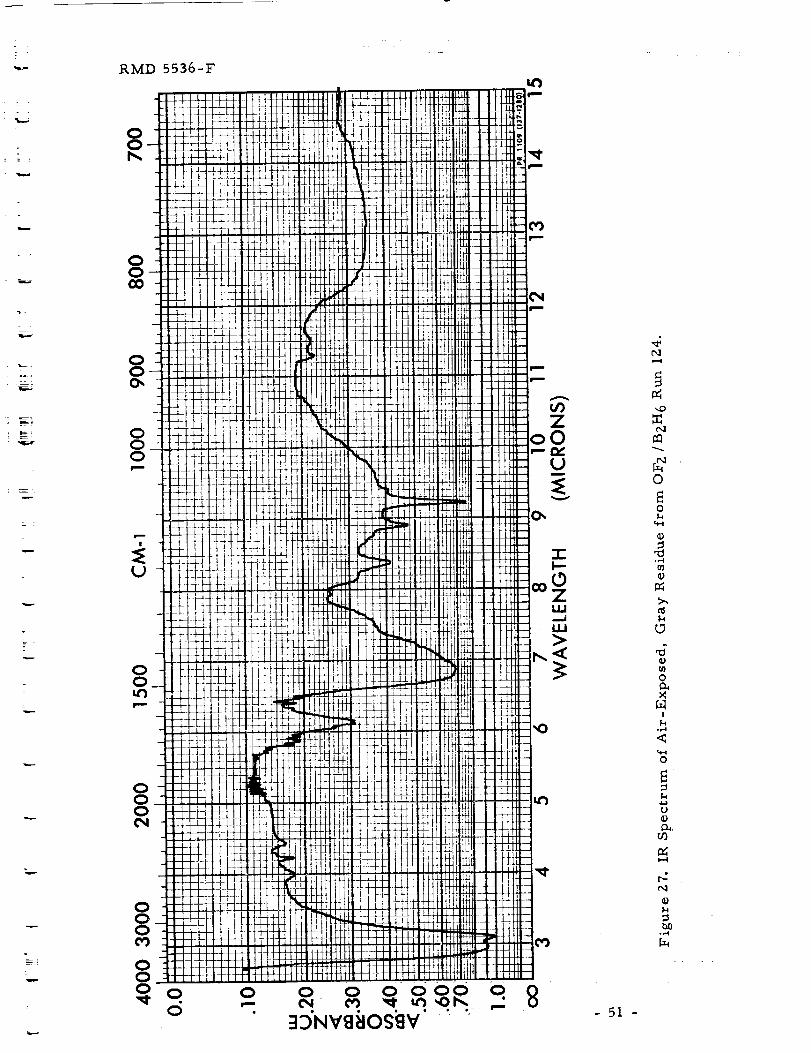
--i
w
RMD 5536-F
OO
OOO0
OOO_
OOO
OO
OOO
OOO O
O
O o o _ooo o3jNV88OS_]V - 51 -
,,o
O
O
a_
¢)
O
!
.i-4
O
I--I
r-:t-,.l
°_"1
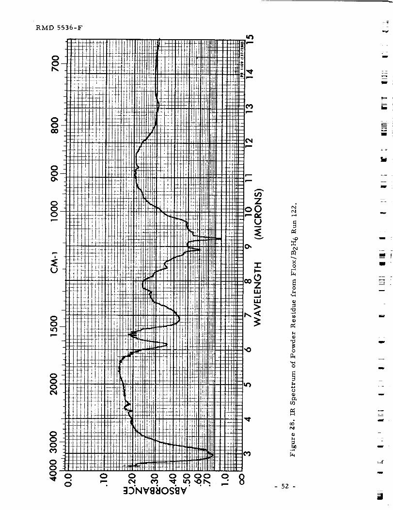
RMD 5536-F
OO
L
I!
o g g 8ggR.q 8:IDNVI]_IOg_V " " '-
NO
,--,I
O
",I=I
'O
o
o
I-4
- 52 o
l
i
:
B
II
=
I
i :
m
i
i
aaron,
u
RMD 5536-F
5
r--
L_
l.ag
Upon removal of the sample plug from the engine following Run 108,
the deposit on the plug was roughly 50% gray - 50% black. However, despite
the nitrogen environment, the sample changed by the following morning to
approximately 5"/0 gray - 95% black. Figures Z2 and 23 are IR spectra of the
black material at two concentrations in the pellets. Figure 24 is a spectrum
of the gray powder. It is seen that all three spectra have significant
absorptions at Z. 9, 6. Z, 7.0, 8.9 and 9. Z microns. The spectra of the gray
material differs from the black material in that the 7.0 micron peak is more
pronounced relative to the other absorptions.
The IR spectra of samples from Runs 115 and 116 are given in Figs. 25
and 26 respectively. Both spectra indicate that the samples contain mostly
the component having the absorption at 7.0 microns. In the Run 116
spectrum, no absorptions above 8.5 microns are present.
The IR spectrum of the air-exposed sample from Run 124 is given in
Fig. 27. The spectrum is quite similar to that of the light gray powder
residue from Run 108 (Fig. 24). The differences are (a) that several
additional absorption bands are readily seen in the spectrum of the air-
exposed sample that are only marginally distinguishable in the earlier
spectrum and (b) that the band at 7.0 microns repeatedly seen in the earlier
spectra is shifted toward shorter wavelengths and is more pronounced in the
air-exposed sample. The new bands that are easily seen in Fig. Z7 are thoseat 4.0, 4. Z, 4.4. 8.4, 11.3 and 11.5 microns.
The IR spectrum of the residue from Flox/BzH 6 Run 122 is given in
Fig. 2.8. Similar absorptions are seen in this spectrum as in that of the
air-exposed, OFz/BzH 6 material. Differences are only that the bands at 7.0
and 8.4 microns are less pronounced in the spectrum of the Flox/BzH 6 residue.
From the IR spectra, it appears that the samples contain at least three
components, one of which is HzO as indicated by the absorptions at Z. 9 and
6.2. microns. The other components are less certain at present. Neither
H_BO_ (boric acid) nor BzO 3 is observed in the spectra. However, boron
nitride BN may be present. For comparative purposes, the IR spectrum ofBN is given in Fig. 29.
A sample of the air-exposed residue from OFz/BzH6 Run 124 wasmixed with concentrated sulfuric acid and introduced into a flame. A
positive flame test (green color) for borates (BOs =, B407 =) was obtained.
The IR spectra, however, indicate that neither H3BO s (boric acid) nor BzO sis present in any of the samples.
The gray air-exposed residue of Run 124 was also examined on an
X-ray diffractometer. Two strong, sharp peaks were obtained at 6.10 and
3. Z0 _. In addition, weak, broad peaks were obtained at 5.47, 2.91 and
- 53-
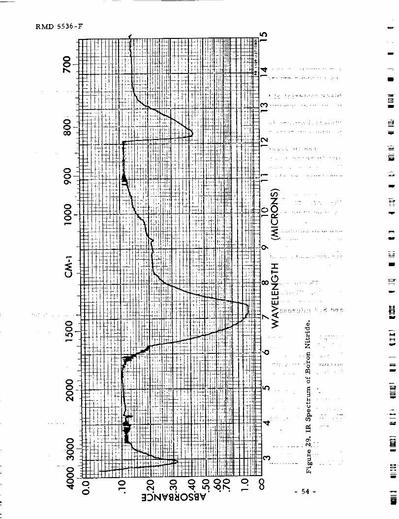
RMD 5536-F
OOO_
OOO
U
OO
OO'O
- 54-
w
I
I
I
I
l
u
I
I
"--4
L
--m
RMD 5536-F
2.24 _. The latter peaks are unidentified but the t_o strong ones are
characteristic of BzO 3 and H3BO s although other lines from these crystals
were not observed. It is possib_le that Comp0unds invoiving B, O and F
would have similar d-spacings as BzO 3 and H3BO 3 both of which have been
ruled out by the IR results.
The residues from OFz/BzH 6 Runs 108, 115 and 116 were examined by
X-ray powder diffraction with a Debye-Scherrer camera. Theblack powder
residue from Run I08 exhibited strong peaks at 6. 17 and 3.24 A which agree
reasonably well with the two strong peaks obtained from the Run 124 sample
with the X-ray diffractometer. No other lines were detected in the Run I08
sample but a strong amorphous band at 15-25 ° 2 0 was observed and suggests
the presence of elemental, non-crystalline boron. The amorphous band was
the only characteristic given By theRun I15 residue, however, the Run If6
residue gave the same powder pattern as the black Run 108 residue. From a
geometrical standpoint, then, the Run 115 residue differs from the residues
of Runs 108 and I16 and the latter two are the same.
Summarizing the various analytical results gives:
a) Similar species are present in the residues formed by either
OF z or Flox with BzH 6.
b) The residues consist of various concentrations of at least
amorphous elemental boron, HzO , and two other components
one or both of _hich are borates (BOs- , B407=).
c) Neither H3BO 3 nor BzO 3 is present in the samples but BN may
be present.
d) From a geometrical viewpoint, the samples of Runs 108
(black residue), i16 and 124 appear similar and the Run If5
sample is different.
One would expect that the composition of the residues from the various
runs would differ since tail-off floras _ere different. On an idealized basis,
the lagging propellant to "run-out" and the duration of flow of that propellant
after the other propellant stops is as follows:
OFz/BzH6 Run I08:
OFz/BzH 6 Run If5:
OFz/BzH 6 Run 116:
OFz/BzH6 Run IZ4:
Flox/BzH 6 Run IZ2:
BzH 6 for 83 ms ec
BzH 6 for 147 msec
OFz for 216 msec
BzH 6 for 78 ms ec
BzH 6 for 71 msec
=_
-55 -
RMD 5536-F
These values _'ere calculated based on step-function mass flo_'rate profiles
with steady design flowrates based on design chamber pressure but allowing
for actual tank set pressures and propellant temperatures. It is to be
recalled that in the present test system, the total propellant loaded into each
run tank is injected into the thrust chamber in eacl_ run and is follo_'ed
automatically by a short helium purge. The large tail-off changes indicated
above _ere obtained by simply loading less than and more than the normal
amount of OFz in its run tank for the respective runs.
The fact that the Run 115 residue differs geometrically from all others
appears due to its very long fuel tail-off which left primarily elemental
amorphous boron and the component having the absorption at 7.0 microns.
The absence of absorptions above 8.5 microns in the Run If6 residue
apparently is linked to the long oxidizer tail-off of this run.
m
m
I
m
u
m
v
- 56-
W
_u
w
w
m
m
H
I
V
m
gl
RMD 5536-F
•L i
L--
l J
• =
m_
Z
.._
V. DISCUSSION OF RESULTS
In this
first. Then,
described in
necessary to
and, finally,
program are
section, the effects of the programmed variables are discussed
the mechanisms that control start-up in the test system are
some detail. Some design concepts and operational procedures
ensure reliable start-ups in space-ambient engines are given
the problem areas that _ere encountered during the present
des c ribed.
A. EFFECTS OF THE PROGRAMMED VARIABLES
The parameters investigated are: hardware and propellant
temperatures, propellant lead/tag, type of valve/injector coupling, run tank
ullage volume, injector configuration, design chamber pressure, type of
propellant valve, and oxidizer (OF z and Flox). These are discussed in the
following paragraphs.
I. Effect of Temperature
In the Phase I program (Ref. 1), it was found that ignition delays
of OFz/BzH 6were insensitive to temperature. In those tests, hox_'ever,
either the propellant temperatures were constant and hardware temperature
was varied or hardv_are temperature was constant and the propellant
temperatures varied. Because of the unexpected nature of that finding,
tests were conducted in the present program in _hich both hard,'are
temperature and propellant temperatures were varied together. Table VII
summarizes the pertinent warm and cold runs. Again, it is found that the
ignition delays ("Main Chamber Ignition") are essentially constant.
Although temperature does not affect the overall ignition delay
time, the table shows that temperature does affect the rate and type of
filling of the injector manifolds. In the cold runs, water hammer pressure
peaks in the manifold pressure traces indicate hard liquid filling of both the
fuel and oxidizer manifolds. This is to be expected as the vapor pressures
of the propellants, even at the injector temperature, are _ell below the tank
set pressures. For example, the vapor pressures of BzH 6 and OFz at -200°F
are approximately I. I and 46 psia, respectively, x_hile the corresponding
tank set pressures for the cold runs were approximately I78 psia for both
propellants.
In the three warm runs, hard liquid filling again occurred in the
fuel manifold as one would expect (vapor pressure of 38 psia at -100°F
versus a tank set pressure of 188 psia). It is noteworthy, however, that the
time required to achieve hard liquid filling of the fuel manifold is consistently
longer in the warmer runs.
- 57 -
RMD 5536-F
_
zo u
o
_ O
I ! I
L_ _]
I I I
I 0 0 0
un 0 _ 00'_ _ _'_
I I I
0 0 0
I I I
ooO
0
0
0
n__C_ .,4
C}" 0_
_ .,-_
r_ U'
,
"l:J,-_ ._
n_J
u_ _ _
O
m
op.tO _ "
_ _ 0
O
o
<
0_<
0
0O_
<
o
H
<
I I I
o]
0 0 00 _ 0
I ! I
0 0 00 I_- 0
I I I
_"L 0 0 0
0 i_" 0
I I I
,==.i
0 _e_ _ 0
o
4-)
0 o
_ .,_
0 _ _
0 0
o U _ I:_
_ 0 _ _ ,-_o ._
e_
u_
O
m0
_-_
0¢3
O
0,1
O
O
IM
O,1
O
4-)
E)
,.I:1
0
I0._
n_
b.I)o,-i
000;.--,
0
p._u
0
m
O
m _4_
t.-i
O _
U _
NI
4_O
Z
_J
.!O
O
t-i
@
_2
4.1
1.4
©
,.el
4-1m
or4
_d
i:mi
o
0
o
7- 01_ .,.._0 4_
"_. _
°_ N
4o _
t:_ I:m
_ ,r-i4_
O _
o_.-i
_._
2-
i
N
I
I
- 58-
RM_D 5536-F
i :
In the case of the oxidizer manifold, hard liquid filling generally
did not occur in the warm runs. As Table VII indicates, the injector (and
chamber_ was conditioned to -100°F while the OF z run tank was conditioned
to -170°F. The vapor pressure of OF z is 490 psia at the former, warmer
temperature but approximately If5 psia at -170°F. Since the OF z tank set
pressure in these "warm" runs was approximately 180 psia, water hammer
pressure peaks could occur only for effective propellant and injector
temperatures of -150°F or below. This temperature was not reached in two
of the warm runs but evidently was in the third (Run 94).
Other evidence that Run 94 was in fact colder than the other two
comes from the oxidizer valve current traces. The decreased resistance of
the solenoid valve coil with decreasing temperature results in a valve current
deflection that varies with coil temperature. The valve current deflection in
Run 94 is noticeably greater than in Runs 9I and 96, indicating therefore thatthe valve is colder in Run 94.
The effect of temperature on tliborane manifold filling was observed
previously and is discussed in some detail in the Phase I report (Secs. V.B.Z
and 6 of Ref. 1}.
For completeness, other previously observed temperature effects
on OFz/BzH 6 start transients are summarized below.
Temperature-caused high frequency oscillations in the OF z
manifold were observed in Phase I and are discussed inSec. V.A.2.b of the
Phase I report (Ref. 1I. This "cool-down" phenomenon was not observed in
two runs of Phase II having otherwise appropriate temperature conditions,
i.e. OF z at -320°F and the injector at +70°F (Runs 62 and 68). However,
these runs had the large rather than the small ullage run tanks. The
significance of this difference is not apparent at present.
It was found also that in runs with warm BzH 6 (i.e. -10°F) strong
reactions occurred in the OF z manifold prior to ignition (Sec. V.B. 6 of
Ref. I}. These reactions sometimes caused a momentary interruption of
the oxidizer flow due to the pressures generated in the manifold and resulted
in delayed ignition in the thrust chamber.
2. Effects of Propellant Lead/Lag
In the Phase I program (Ref. I) only one ignition spike was
observed. It occurred in one of the OFz/BzH 6 runs and, furthermore, it
occurred in the only run made with an OFz lead (Run 37). To determine
whether the OF z lead was significant, tests with varying leads mere conducted
in the present program. One series was OFz/BzH 6 Runs 74 through 88 (but
excluding No. 78 which was a test of explosively actuated valves,
- 59 -
RMD 5536-F
Sec. V.A. 8 below' I. This series _as made with the 100 psia chamber, nine
element injector, small ullage run tanks and close valve/injector coupling
(Table V 1. The temperature conditioning objective was -200°F for the
propellants and the hardware.
Eight meaningful runs _,ere obtained in this series and they
covered electrical leads from 3 msec fuel to 14. 5 msec oxidizer. (The other
runs suffered from a "soft" fuel or oxidizer feed which indicates less than the
full, proper flowrate into the thrust chamber, see Sec. V.A. 3, below). The
eight meaningful runs are given for convenience in Table VIII which sho_s
that t_o of the eight runs had electrical fuel leads while the other six runshad electrical oxidizer leads.
Both fuel lead runs exhibited smooth start transients but,
significantly, four of the six oxidizer lead runs exhibited ignition spikes inthe thrust chamber.
Table VIII also shows that the minimum ignition delay occurred
with a slight oxidizer lead (electrical) and that the ignition delays with all
other reasonable leads (i.e. 3 msec F to 8.5 msec Ox) _ere nearly
constant.
The ignition delays referred to above are the delays that precede
a rise of chamber pressure to a substantial level. Evidence of chemical
reactions prior to a substantial rise in chamber pressure is frequently
observed by the optical instrumentation. The first occurrence of optical
emission is given in Table VIII in the column labeled "Low Level Optical
Emission". In every case, this initial emission occurs prior to hard liquid
filling of the injector by either the fuel or oxidizer and sometimes occurs
prior to the start of manifold main pressurization by one of the propellants.
In other _-ords, reactions with emission can occur in the thrust chamber
when the flow of one propellant is two-phase through the injector orifices
while the other is only low level vapor flov_ that arises from poppet cocking
(Sec. III.A. 3. a).
The reactions that produce the low level emission apparently act
as a pilot flame _'hich allows essentially immediate, full reactions upon
hard liquid filling of injector manifolds by both propellants (compare
"Ignition Delay" times to "Hammer in Manifold" times in Table VIII). In
this case, then, "Main Ignition" occurs when the full mass flow of both
propellants into the chamber occurs.
Since main ignition depends upon attainment of full mass flow of
both propellants, it is of interest to consider the valve and fluid mechanical
events that occur during start-up. A comparison of these events for the OFz
and BzH6 in the subject eight runs is given in Table IX. Although the times
- 60 -
RMD 5536-F
_ I_" h- _ _ _ _
o_ °1_I
t::: t:,. _
u>
,,-.i
- 61 -
ou
.+,-i
P_
l,-i
_0
0
fJ
.,-t
.+-.i
i
0",
O3
lit
+J
.,;,..,i
Oo0 0
0
'_ 0
tl
_-_-
0
RMD 5536-F
of the events are not perfectly reproducible, it is clear that a longer time is
required to achieve full mass flow of the OF z than of the BzH 6 in the subject
hardware configuration under the specific operating conditions. It follows
from the preceding, then, that the minimum delay to main ignition will occur
with a short oxidizer lead. This is found to be the case (Run 81, Table VIII)
however the difference is quite small.
TABLE IX. COMPARISON OF OXIDIZER AND FUEL START-UP EVENTS _
Time from Signal to:
Ox Valve Fuel Valve
msec msec
Cocking of Valve Poppet
Start of Low Level Manifold Pressurization
Start of Poppet Transfer
Valve Full Open
Start of Manifold Main Pressurization
Hammer in Manifold
6-7 5.5-6
7-8 6.5-8
11-14 IZ-14
15-17 15-17
18-ZI 15-17
'_27 -Z9 "_22 -24
_Engine Configuration and Temperatures: I00 psia chamber,
small ullage run tanks, close valve/injector coupling,
Tin j = TOF z = TBzH6 = -200°F.
(Serected runs from 77 to 88)
9-pair injector,
Referring again to the effect of propellant lead/lag on the
character of the start transients, further evidence that an OF z lead can
produce undesirable pressure transients is seen in the first block of tests in
Table VI. In this series, which differed from the series discussed above in
temperatures, valve/injector coupling and run tank ullage (Table V), four of
the five runs with oxidizer leads resulted in ignition spikes. Two fuel lead
runs and one no-lead run exhibited smooth start transients.
In the one non-spiking oxidizer-lead run (Run 62), the injector was
conditioned to ÷70°F which resulted in massive flashing of the incoming
propellants (Ref. I, p. 48) and consequently a lower rate of massflow
increase into the thrust chamber. Although no spiking occurred, there _'as
a moderate (140 psia) initial overpressure in this run.
In all other series of runs, ignition spiking generally did not occur
regardless of the propellant lead condition. In total, of the Z30Fz/BzH6 runs
having an electrical oxidizer lead in Table VI, nine or 39°_0exhibited ignition
spikes. As in the Phase I program, no ignition spikes were observed in the
Flox/BzH6 runs.
- 6Z -
RMD 5536-F
¢ -_v
L_
%_,
3. Effect of Valve/Injector Coupling
In the "normal" valve/injector coupling configuration
(Sec. III.A.4), short stand-off tubes are used to isolate the injector which is
thermally conditioned in one bath from the propellant valves _hich are
thermally conditioned in two additional baths. This method assures that the
initially flowing propeilant is at the desired propellant temperature. The
stand-off tubes, however, unavoidably cause somewhat larger dribble
volumes.
To reduce dribble volumes, the stand-off tubes were minimized,
resulting in the configuration designated "close" valve/injector coupling. In
this configuration, the valves are no longer conditioned with the propellant
but rather with the injector. Since the injector was generally conditioned to
a warmer temperature than the propellants, difficulties in obtaining hard-
liquid filling up to the valve seats increased. Under these conditions of
warm valve/injector and cold propellants, the propellants that condensed in
the run tanks during the initial loading phase would run down the feed lines
from the tanks and vaporize in the _'arm propellant valves. If the vapors
then rise into the run tanks and re-condense, a heat pipe action is set up
which gradually cools the valves to a degree that allows hard-liquid filling
up to the valve seat. This process is time-consuming, however. Another
practical consideration is that valve static leakage apparently was greater
with OF z vapor than with OF z liquid. A long hold time to accommodate the
vaporization-condensation cooling process could cause propellant loss and
vacuum degradation when using the solenoid metal-seated propellant valves.
A consequence of this valve conditioning problem is that a number of runs
exhibited improperly soft fuel or oxidizer feeds as determined from injector
manifold pressure traces. The evidence is a lack of water hammer pressure
peaks under conditions where hard-liquid filling should have occurred.
Although ignition nevertheless occurred, initial propellant massflow rates
differed and therefore these runs are not included in the data summaries of
Table VI.
Considering only runs exhibiting hard-liquid filling, several runs
with normal and close valve/injector coupling are compared in Blocks I and
II of Table X. In the table runs with similar lead/lags are paired where
possible. All runs were made with the I00 psi chamber and nine-element
doublet injector. The temperatures of injector, OF z and BzH 6were all
nominally -Z00°F for the BlockI tests. In the Block II tests, the OF z run
tank was conditioned to -320°F. The BzH 6 tank and injector were
conditioned to various temperatures from -I00 to -250°F (Table V).
From the viewpoint of dribble volume alone, ignition delays to
main ignition should be shorter with the close valve/injector coupling due to
its smaller dribble volume. The Block I tests follow this trend, however,
- 63 -
LJ
W
I
U
u
I
_d
I
II
Iil
M
I
m
RMD 5536-F
the Block II tests do not. In both cases the differences are small and, in
fact, are generally within reproducibility.
Regarding spiking tendencies, spikes occurred with close coupling
in the Block I tests and with the normal coupling in the Block LI tests. In
short, the coupling configurations tested had little effect on start-ups
provided the tests were initiated with hard liquid filling of the feed systems
up to the valve seats.
4. Effects of Run Tank Ullage
The very small run tanks used in the Phase I program were
replaced for some tests in the present program by run tanks of twice the
volume. However, because line volumes were large by comparison, as
discussed in Sec. III. A. 6, the resulting change in ullage volume was
relatively s mall.
Several tests with the t_o ullage voh_nes are summarized in
Table X under Block III, As in the case of the valve/injector coupling
configurations, there is little difference in the ignition delays to main
ignition with the large and small ullage systems. Furthermore, no
consistent significant effect on manifold filling characteristics by either
propellant was observed.
5. Effect of Injector Configuration
Only very limited tests were conducted in the Phase II program
with the single-element doublet injector in the 100 lbf thrust engines since it
is considered to be a poorer performing injector than the nine-element one
and its effect with Flox as oxidizer was determined previously (Ref. 1).
Runs 65 (9-pair) and 58 (1-pair) were made _'ith the same
hardware configurations, except for injectors, and with the same propellant
lead, 13 msec OFz (Table V). Injector temperatures in both cases were
approximately -200°F which, from vapor pressure vs. tank pressure
considerations, leads to hard liquid filling of both the OF z and BzH 6 injectormanifolds.
The test data for Runs 65 and 58 in Table VI show as expected that
hard liquid filling occurs faster in the case of the 1-pair injector which has
the smaller dribble volume. Filling times based on water-hammer pressure
peaks (comparatively weak with the 1-pair injector) for OF z and B2H 6 were
2I vs. 29 msec and 29 vs. 33 msec, respectively, for the I-pair and 9-pair
injectors. Low level optical emission was observed earlier with the l-pair
injector (I9 msec vs. 27) and ignition delay for main ignition was shorter
(29 msec vs. 33.5). This result agrees _ith the previous finding which was
based on Flox as the oxidizer.
- 65 -
RMD 5536-F
Other runs which are comparable (except for temperatures) are
Runs 54 and 60 (zero propellant lead) and Runs 56 and 63 (13 msec electrical
fuel leadl. As expected, the response of the l-pair injector is faster.
6. Effects of Design Chamber Pressure
The earlier finding that ignition delays increase with decreasing
design chamber pressure (Ref. l) was corroberated in the present program.
Previously, the nine-element injector was used whereas, in the present case,
the single-element injector was used with the 20 and 100 psi design Pch
chambers (Runs 108 vs. I03 and I04). Based on the optical ignition detector,
ignition delay for main ignition increased from 21 to 26 msec.
7. Bipropellant Valve Tests
Two tests were made with the Hydraulics Research torque-motor
bipropellant valve described inSec. III.A. 3. c. The valve was used in
conjunction with the 100 psi chamber, 9-pair injector and large ullage run
tanks (Runs 98 and 99, Table V). The valve was thermally conditioned with
the injector, however it was also subjected to the propellant vaporization-
condensation cycle discussed above in Sec. V.A. 3.
The first run of the pair proceeded normally. It may be compared
to Run 90 _hich used the solenoid valves but which otherwise was made under
the same conditions including an electrical lead/lag of zero. Pertinent data
are compared in Table XI. The table shows that full liquid filling of the
injector manifolds, as indicated by water hammer pressure oscillations,
takes slightly longer in the case of the bipropellant valve despite the fact that
this valve reaches full open first. Since attainment of injector hard liquid
filling takes longer, the delay to main ignition is also longer in the case of
the bipropellant valve. The difference, however, is small. The start-up
transients in both cases _'ere smooth.
Run 99 was intended as a duplicate of Run 98 to gain further
experience with the bipropellant valve. In the second run, however,
apparently a double malfuncti0n occurred although the two may stem from the
same cause. A description of the test follows.
The test hardware and both propellants were being conditioned at
-200°F in preparation for Run 99. The fuel, whichhad been loaded into the
prefill tank, was in process of being transferred into the fuel run tank when
a loud metallic click wa's heard over the intercom system. The click occurred
at approximately If0 seconds into the 120 second transfer sequence. At the
completion of the fuel loading, the transducers were read-out on the digital
voltmeter to determine if all conditions were normal. However, the digital
voltmeter readings were intermittent and erratic. The meter would not
- 66 -
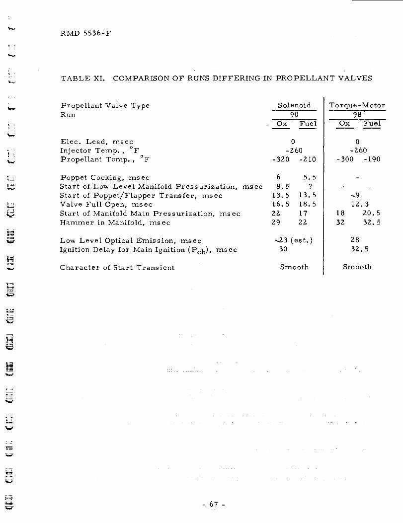
RMD 5536-F
TABLE XI. COMPARISON OF RUNS DIFFERING IN PROPELLANT VALVES
.:7
v
Propellant Valve Type
Run
Elec. Lead, msec
Injector Temp., °F
Propellant Temp. , oF
Poppet Cocking, msec
Start of Low Level Manifold Pressurization,
Start of Poppet/Flapper Transfer, msec
Valve Full Open, msec
Start of Manifold Main Pressurization, msec
Hammer in Manifold, msec
Low Level Optical Emission, msec
Ignition Delay for Main Ignition (Pch), msec
Character of Start Transient
ms ec
Solenoid
90
Ox Fuel
0
-260
-320 -210
6 5.5
8.5 9
13.5 13.5
16.5 18.5
22 17
29 22
_23 (est.)30
Smooth
Torque -Motor
98
Ox Fuel
0
-260
-300 -190
"_9
12.3
18 20.5
32 32. 5
Smooth
- 67 -
RMD 5536-F
provide the proper display from the internal calibration signal and the results
of the read-out were questionable. The decision was made to continue since
the B2H 6 was already loaded.
The oxidizer was loaded into the run tank by remotely observing
the visual gauge on the OF z measuring tank. At the completion of the loading
process the digital voltmeter seemed to be working again. All readings were
approximately correct except that the altitude chamber pressure reading was
0.560 psia instead of the normal 0.000. The OF z was conditioned to -200°F.
The run was conducted following the usual sequence. At the
completion of the test run, the altitude pressure reading was Z1.95 psia.
normal run produces pressures of 2-3 psia.
A
The photographed oscilloscope data traces indicate a normal
looking oxidizer manifold trace. However all other traces are not normal.
The chamber pressure traces deflect downward rather than upward, the fuel
manifold trace looks as though there was a "gas flow only" condition and both
the propellant entry detector and tho ignition detector show erraticc ombus tion.
The pressure of the helium cylinder which is used to pressurize
the liquid OFz showed a loss of approximately 200 psi.
The conditioning bath material was removed from the chamber/
valve assembly and the hardware was examined for signs of failure. There
was none externally visible. The system was scrubbed and maintained at
vacuum condition overnight.
The following day it was determined that both sides (fuel and
oxidizer I of the valve leaked. This was done by applying an upstream
pressure and observing the altitude chamber pressure. The valve was then
removed from the system and examined. It was confirmed that both the
oxidizer and fuel ports leaked through. Visual examination of the outlet ports
showed a circular metallic obstruction between the flapper and the seat in the
oxidizer port. The size and shape of the obstruction seemed such that it was
too big to have entered the valve from the outside, The valve was actuated
causing the obstructing piece to fall away from the seat inside of the valve.
The oxidizer side then sealed properly. The fuel side of the valve still
leaked through. Following the finding, the technician reported that the valve
had exhibited an erratic sealing condition on the fuel side _hen it was checked
out on arrival but that the condition cleared up after one or two cycles and the
valve then performed properly.
Based upon the above information it is believed that the fuel port
remained open during the major portion of the fuel loading operation for
m
i
iw
a
II
i
- 68 -
___. RMD 5536-F
=
Run 99 and that the fuel was charged directly into the altitude chamber. The
loud metallic click heard over the speaker system x_as the fuel port suddenly
sealing. The valve opened normally at the fire signal but failed to shut do_'n
properly because of the obstruction in the oxidizer flapper/seat area. This
allo_'ed oxidizer pressurizing gas (helium) to continue to charge the altitude
chamber until the safety valves x_ere shut off in the shut down sequence. It
is not kno_'n at present whether the erratic closing of the fuel side of the valve
is related to the foreign metal piece whichprevented proper closing of theoxidizer side of the valve.
L .
V
E_7
m
i
m
The valve was returned to the manufacturer for their evaluation of
the cause of failure. Their findings as reported via telecon are summarized
as follows (Ref. 9):
i) The oxidizer seat and flapper were in "like-new" condition.
ii)
iii)
No foreign material (such as described above) was noticed in
the oxidizer side of the valve. However, the valve had been
reworked several times to put in new torque tubes prior to the
present testing with OFz/BzH 6. It is possible that a piece of
foreign material may have been overlooked in the subsequent
disassembly.
The fuel seat and flapper w'ere partially eroded making sealing
impos s ible.
iv) The fuel seat and flapper were covered with a reddish
crystalline material similar in appearance to iron rust.
It is not known what reaction could have taken place between BzH 6
and the seat and flapper material to form the resultant red deposit. The seat/
flapper material is made from a mixture of 96% tungsten carbide and 4% cobalt,
the latter being used as a binder. Since the deposit w'as not analyzed,
positive identification is not possible.
The manufacturer indicated that North American Aviation Co. had
a similar experience with an identical make valve using NzO 4 and MMH.
Analysis of the contaminant proved it to be iron rust.
In the present case, however, iron rust seems unlikely as the
causitive agent of failure since the valve employs 20 micron filters in the
inlet ports and the fuel seat material was actually corroded. Furthermore,
the corrosion cannot be attributed to the OF z since the oxidizer seat and
flapper remained in like-new condition.
L--
69-
RMD 5536-F
1
transient,
a run was conducted using tto explosively actuated Conax valves.
valves are described in some detail in Sec. III. A.3. b.
Explosively Actuated Valve Test
To determine the effect of zero propellant leakage on the starting
i.e. in the absence of any pre-flow arising from poppet cocking,The
In the subject run (Run 78), the propellants (OF z and B2H6) t ere
conditioned at -Z00°F in small ullage run tanks contained in separate
conditioning baths. The Conaxvalves (close coupled), nine-pair injector and
I00 psia chamber were conditioned at -I00°F (Table V). ....
The explosive valves were initiated simultaneously _'ith 24V DC
fused for 5 amperes. There t as a loud report closely followed by the sound
of falling shrapnel. Examination of the hardware shot'ed that the oxidizer valve
body plug had blot n out. The resultant reaction drove the valve body back
pivoting on the tubing from the oxidizer run tank. This resulted in the fitting
connecting the valve to the injector to pull free from the valve body. The
injector feed line was bent at the injector face and the weld was broken. In
addition, the coaxial cables were pulled loose from the Connectors to the
oxidizer injector manifold transducer and from the lot' sensitivity chamber
pressure transducer. The protective burst disc in the oxidizer feed line (set
for I000 psi) had ruptured. There was no other damage. Figure 30 shot's
the hardtare, _ith the chamber conditioning bath removed, on the day
folloting the test.
The test data shot ed that the oxidizer manifold and the lot'
sensitivity chamber pressure traces vanished one millisecond after
actuation of the fire signal. Propellant entrytas indicated at I msec,
ignition detection and start of chamber pressure rise (from the high
sensitivity chamber pressure trace) occurred at 1.5 msec. The ignition
detector trace also shot'ed that the combustion flame started to extinguish
at 32 msec and t as completely out by 44 msec.
The damage was very local. Figure 31 shows two viet's of the
injector and the explosive valves used for the test. Figure 32 shot's a
comparison between a new valve and=the damaged v a!ve. The c aus e of th e
failure is attributed to fuel rich squib combustion products blot'ing by the
shear ram into the downstream cavity of the valve. Shearing of the integral
valve body diaphragm caused the OF z and the squib combustion by-products
to mix in the valve body and resulted in a detonation which blet' out the valve
body plug as described above.
It must be pointed out that the Conax valves were designed for a
minimum operating temperature of -65°F whereas they were conditioned to
-I00°F for the run. Furthermore, vaporization-condensation cooling
during the OF z loading operation reduced the temperature to about -150°F.
I
W
l
w
u
U
g
a_
=
lib
IIR
R_
t_
W
m
W
RMD 5536-F
.r4
t_
or-4
O
)4
C
O
o
4_
t_

W
W
m
m
Bw
g
d
I
w
Iff
ImI
li
vl
i
=
RMD 5536-F
| ?T
L_
-7
w
Figure 31. Injector and Explosive Valves after R,m 78

J
w
u
R
i
i
B
I
I
W
I
/, _:_x ¸ :_ _ _ _ - _ _ _-_ ; : _ _±z__ :_ _ : : " . :
NI
Mi
H
w
m _
u
U
_UW
=
=_
I
= _
n
I
I
RMD 5536-F
t :
i °
t__
L_
Figure 32. Explosive Valve Used in Run 78 and New Valve
w

m
ira#
UE
U
U
_m
..,....
=
W_
: RMD 5536-F
:
=
F i
±
L_ i_cc_
r_t _
L--
--Z.
--=
z
Two candidate solutions to the problem a_e offered: (a) redesign
the charge composition to produce oxidizer rich combustion blov,-by products
which are less reactive with OF z and retain the present hardware
configuration, or (bI redesign the valve to prevent blox_'-by by utilizing a
design such as the Rolldex-Rolling Metal Diaphragm Explosively Actuated
Valve being developed by the Elkton Division of Thiokol Chemical Corporation
for the Jet Propulsion Laboratory (Ref. 10).
No further testing of explosive valves was conducted.
9. OFz- Flox Comparis on
Five runs were made in the present program with Flox as the
oxidizer in place of the OFz (Runs 118 to IZ2). These runs are discussed
first and then these and other Flox runs from the Phase I program are
compared with similar OF z runs.
The first run, Run I18, _'as made under the same conditions as
Run I0 from the Phase I program (Ref. i) to check reproducibility. The
results of these two runs are given in Table XII. The Run I0 data includes
additional valve opening data which is reported for the first time.
Table XII shows that the duplicate runs repeated quite well despite
a lapsed time of 15 months between them. It is true that the "Ignition Delay"
for Run 10 is listed as 24 msec in Table XII but as ZZ msec in Reference 1.
The small change is due to a slightly different definition of ignition delay in
the two places.
The effects of propellant lead/lag at near isothermal conditions
(approximately -ZS0°F) were examined in Runs IZ0 to IZZ (Table V). As
stated in Table VI, the start transients were smooth in all cases including
the Flox-lead case. This was expected based on the results of the Phase I
program in which no ignition spikes occurred in any of the F[ox runs.
The most striking difference between Flox and OFz as oxidizer
is the lack of ignition spikes with the former but the occurrence of ignition
spikes with the latter, especially with an oxidizer lead.
Manifold filling characteristics also differ between the two
oxidizers due to their physical properties. Hard liquid filling of the injector
occurs quickly under the test conditions with OF z and the injector at -200°F
or below. On the other hand, in F[ox Runs IZ0-12Z the hardware and
propellant temperatures (approximately -Z50°F), the Flox tank set pressure and
the vapor pressures of 02 and F z are such that the O z component would be
liquid--following an initial, brief flashing phase--but the Fz component
would be at or somex_'hat above boiling point conditions. Therefore, water
- 74 -

I
J
a=_a
I
U
U
iu
UHu
H
W
W
aS_
w
t_a
i[]l ]!
_i_ imlF
TIu
_L-W
w
U [
U ¸
RMD 5536-F
%.._-
L
_L.j
L_
,w_f
E
TABLE XII. REPRODUCIBILITY OF FLOX/BzH 6 TESTS
Valve Signal
Cocking of Valve Poppet
Start of Lo_ Level Manifold
Pressurization
Start of Poppet Transfer
Valve Full Open
Start of Manifold Main
Pressurization
First Main Pressure Peak in
Manifold
Ignition Delay for Main Ignition
Character of Start Transient
Time from Signal-to-Leading
Valve to: (millisecond)
Run I0 Run I 18
_ Oxm
Fuel Ox Fuel
0 0 0 0
7 5 7 6.5
7.5 6 _.8 7
12 IZ. 5 12.5 14
16 16 14 16.5
18 17 17 18
Z6 (a) 23. 5(b) Z6 (a) Zl. 5(b)
24 24
Smooth Smooth
Notes: Engine configuration:
Temperatures:
(a)
(b)
100 psia chamber, 9-pair injector, small
ullage tanks, normal valve/injector coupling,
s olenoid propellant valves.
Tin j = -100°F, TFlox = -320°F and
TBzH6 = -100°F.
Times are to first sharp pressure peaks (Oxmanif01d
disturbances). No Flox_'ater hammer %vas observed.
Times are to start of fuel _ater hammer in injector manifold.
L_
- 75 -
RMD 5536-F
hammer pressure peaks would not be expected.
observed (Table VI).
B. START-UP PROCESSES
Only soft low peaks were
A descriptive accounting of the physical and chemical processes that
occur during start-up under the test conditions is given below. First, the
fluid mechanical aspects are discussed and then the chemical aspects.
Upon application of voltage, a magnetic field begins to form in each
solenoid propellant valve. At some point when the magnetic flux is still not
great enough to overcome the unbalanced pressure and spring load forces,
the poppet adjusts radially to the magnetic field. With the metal-to-metal
seats, this cocking of the poppets opens Small leakage paths through which
propellants pass into the injector manifolds. Since the pressure is low'
(<13 microns), the propellants flash vaporize and slightly pressurize the
manifolds. This very low "pre-flow" starts 6-7 msec following application of
voltage and lasts until l 1-14 msec at which time axial transfer of the poppets
starts. The solenoid valves are full open at 15-17 msec.
With start of poppet transfer, liquid propellant begins to flow into the
injector manifolds where it undergoes vaporization to a degree that depends
on the propellant temperature and the valve/injector temperature(s). As the
manifold filling proceeds and the manifold walls cool due to the vaporization,
propellant passes through the injector orifices first as a vapor, then as a
vapor/liquid two-phase mixture, and finally, provided the temperatures and
tank pressure are appropriate, as all liquid flow. The emerging liquid enters
the low-pressure environment of the thrust chamber and undergoes further
atomization due to internal boiling in the liquid (Ref. 11) and droplet
vaporization (Ref. 12).
For hard-liquid filling of the injector manifolds, the vapor pressure of
the propellant at its effective temperature in the manifold must be less than
the static pressure in the manifold, or approximately the tank pressure
(minus system pressure drops to the injector). This condition is easily met
in the case of the nine-element injector with both BzH 6 and OF z at effective
temperatures of -100 ° and -I70°F or below, respectively. In the case of
Flox, effective temperatures of less than -260 to -Z70°F would be required
for the more volatile component F z.
Under the appropriate conditions, hard liquid filling occurred in the
following range of times (nine-element injector, I00 psia chamber, and
solenoid propellant valves) :
W
Iw
D
IIw
W
L-u i
U
W
m
L=J
U
LJ
U
E
zz_IW
IW
J
76-
,i=
t !
= =
F,
i L
%=-
RMD 5536-F
Propellant
Times to hard-liquid........filling."
From Signal From Start of
to Respective Valve Poppet Transfer
ms ec ms ec
OFz 24-31 _I I- 19
BzH6 19-Z9 5-13
The longest times occurred with the "warm" temperature conditions,
i.e. TOF z = -170°F, TBzH6 = -100°F and Tinj. = -100°F.
The optical instrumentation added for the present program revealed an
important characteristic of the subject propellant systems that was not
detected previously. In the Phase I program (Ref. I), ignition was taken as
that time at which chamber pressure began to develop to significant levels,
indicating the start of significant thrust generation. The added
instrumentation in the Phase II program shows repeatedly the occurrence of
optical emission well ahead of any significant pressure rise.
Of the two optical detectors added (Sec. III. C), the RCA IPZ8
photomultiplier tube in the propellant entry detector system was markedly
more sensitive to optical emission than the ignition sensor detector.
Nevertheless, the field of view of the iP28 was limited by the small field of
the light pipe/window assembly. Despite this, generally the IP28 indicated
the start of visible emission (the tube is insensitive to infrared) x_'ellahead of
any signal from the ignition sensor (Table VI). In fact, usually though not
always the ignition sensor indicated ignition at the same time as the chamber
pressure transducer (Table VI).
The IP28 data says that, generally, visible emission starts very nearly
with the start of manifold main pressurization by the second propellant.
However, in a number of cases, the lPZ8 data shows that visible emission
starts prior to the start of manifold main pressurization by the second
propellant (Table VI). In other words, "first ignition" occurs during the
period of pre-flow of one propellant, i.e. during the very low flox_'that occurs
due to poppet cocking just prior to the start of normal poppet transfer in the
lagging valve. Furthermore, in a fe_' cases, visible emission _as detected
during the pre-flow period of both propellants. In these cases, tx_o of which
were OFz/BzH 6 runs (Nos. 94 and 117, Table Vl) and one x_as Flox/BaH 6 (I18),
first ignition occurred under conditions of very low' gas densities as w'ell as
low temperatures.
Due to the frequency with which visible emission was detected during
the pre-flow of at least one propellant and since these cases encompassed
both oxidizers, all hardware configurations, all temperature levels, the full
- 77 -
RMD 5536-F
range of propellant lead/lags, and both spiking and non-spiking runs, and in
view' of the limited field of view of the IPZ8 detector, it is concluded that
"first ignition" occurs essentially spontaneously upon contact of the low
pressure, low' temperature gaseous fuel and oxidizer and that this first
ignition results in a weak pilot flame. The flame then increases in intensity
as the mass input into the thrust chamber increases provided a reasonable
balance between fuel and oxidizer is maintained. When the mass input of one
propellant lags markedly, the pilot flame remains weak and "main ignition" is
delayed.
Main ignition is defined as the time at which pressure starts to i-ise to
significant levels and corresponds closely to the definition used in Phase I.
Examination of Table VI reveals that main ignition occurs very closely with
hard liquid filling of the injector manifold by the second propellant. The first
indication of pressure rise in the thrust chamber frequently corresponds to
hard liquid filling by the first propellant, however, this result clearly
depends upon the sensitivity of the pressure transducer.
In summary, the striking feature of the vacuum ignition of OFz/BzH 6
and Flox/BzH 6 is the very rapid ignition of the first low' pressure, low
temperature propellant vapors and the attendant formation of a pilot flame to
"ignite" the bulk flow" which follows. The cocking of the solenoid valve
poppets may well be a desirable feature which, by permitting the establishment
of a weak, short-duration pilot flame, promotes smooth starts.
C. PROBLEM AREAS ENCOUNTERED
In this section, problems that were encountered during the program are
listed and briefly discussed. Some were Significant, e.g. freeze-up of the
oxidizer solenoid valve. Others were not harmful but might be in flight-
w'eight hardware, e.g. manifold POPS.
1. Oxidizer Valve Freeze-Up
In two instances (Runs 9Z and 93), the oxidizer solenoid Valve
failed to open upon voltage application. The instances are described in the
following paragraphs.
Preparations for OFz/BzH6 Run 92 were made in the usual way.
This run w'as to be the fourth run following a hardware change from small to
large ullage run tanks. The first three runs proceeded Without incident. In
Run 92, when voltage was applied to the oxidizer solenoid valve, it did not
open although the fuel valve functioned normally. The OF, was then vented
and the area cleared of personnel for about an hour. Upon return, the valve
functioned and sealed properly. A few helium gas runs w'ere made and the
valve seemed to operate in a normal manner. The following day a repeat
- 78 -
W
W
W
W
W
W
W
D
g
U F
JJ7
m_m
m
J
_" RMD 5536-F
i
J
L .
D
= =
run (#93} was attempted but with the same result. The valve was then
removed from the system and disassembled. The poppet and seat were found
to be wet with a straw-yellow fluid which appeared oily. The valve parts had
an OF z odor. The fluid material, which was insufficient for analysis,
evaporated slowly leaving an amber film on the surfaces. The poppet was
etched and scored and had a small nick on the sealing surface. The valve was
cleaned and reassembled with a new poppet (Sec. III. A. 3. a) prior to Run 94.
It is believed that the straw-colored liquid froze in the valve during
temlSerature conditioning and/or propellant loading causing the valve to hang
up. The system was checked for evidence of contaminating fluid elsewhere
although none was found. The nature and source of the contaminant is
unknow'n. As a precautionary measure, however, the OF z supply tank, which
was nearly empty, was replaced and the system was thoroughly flushed and
cleaned. No further action to identify the contaminant was taken due to other
pressures of the program. No other incidents of this nature occurredthereafter.
2. Contamination
In the first run of the Phase II program (Run 49, Table V), some
metal degradation occurred. Examination of the hardware after the run
showed that the lead gasket seal and the Kistler pressure transducer adapter
bolt end in the oxidizer manifold had been slightly burned. Also the pressure
transducer had failed. The injector itself was essentially unharmed except
that the transducer adapter bolt sealing surface was somewhat degraded.
It is now believed that the parts had become contaminated during
the assembly process. The cleaning technique used for the first run of the
Phase II program was changed in one detail from the procedure used during
the Phase I program. The last cleaning step prior to assembly w'as to flush
the parts with Vythene and dry them with Nz. The Vythene was contained in
a small beaker. The test pieces were placed in the beaker and agitated. It
is suspected that the Vythene or the beaker may have contained some
dissolved organic material.
The test pieces for a duplicate run included a new lead gasket and a
blank adapter bolt (one not drilled out for a transducer 1. The pieces were
flushed with jets of container-fresh Vythene (as had been the procedure for
the Phase I tests) dried with N z and assembled. The second run (Run 50) was
conducted successfully. The Phase I cleaning procedure was reinstituted to
prevent a reoccurrence of component contamination.
- 79 -
RMD 5536-F
3. Propellant Valves
The present program did not include as an objective an exhaustive
evaluation of various candidate propellant valves. Nevertheless, as
discussed in detail in preceding sections, three types of propellant valves
were tested and each had its shortcomings. The solenoid valves which were
used for 12I runs during the two consecutive programs suffered primarily
from degradation of the metal-to-metal seals. The problem w'as
circumvented to a large extent by using soft copper poppets but these had to be
replaced at relatively frequent intervals (Sec. HI.A. 3. a). An additional
characteristic of the solenoid valves is the short "pre-flow'" that occurs due to
cocking of the valve poppets just prior to axial transfer (Sec. III. A. 3. a).
However, this characteristic may be advantageous, rather than detrimental,
to start transients since ignition of the weak flows provides a pilot flamefor the bulk flow's that quickly follow.
The bipropellant valve tested operated normally in one run but
suffered a malfunction in the second run. The particular unit had been
reworked several times by the manufacturer prior to the present testing so
that the malfunction was presumably an unfortunate, isolated instance.
The explosively actuated valves tested performed satisfactorily
in the fuel side even at sub-design point temperatures. In the oxidizer side,
however, the fuel-rich squib products came in contact w'ith the oxidizer due
to blow-by and resulted in valve failure. The blow-by problem must be
resolved in order for explosively actuated valves to be satisfactory for OFzS ervic e.
Since each of the three types of valves exhibited significant
shortcomings, the need for improved, highly reliable, flight weight valves for
space storable applications is obvious.
4. Post-Ignition Chamber and Manifold POPS
In tw'o runs, "POPS" occurred shortly after ignition during
otherwise steady combustion. Both runs were made under cold conditions
(Runs 95 and 97, Table V) ....
In Run 95, a "POP" occurred in the thrust chamber during
otherwise steady combustion approximately 10.5 ms ec after ignition.
Evidence of the disturbance is seen also in both injector manifold pressure
traces. The disturbance in the OFz manifold occurred simultaneously with
the chamber disturbance but the fuel manifold disturbance was slightly
delayed. A second, separate disturbance occurred in the OF z manifold
approximately 2 msec after the first disturbance. No evidence of this second
damped oscillatory disturbance is seen in either the fuel manifold or the
chamb er.
= =
W
W
W
z_ !
u
_ =
i.J Z
J
- 80 - U

RMD 5536-F
A very similar, though slightly stronger, damped oscillatory
disturbance also occurred in Run 97. This disturbance occurred only in the
oxidizer manifold during otherwise steady conditions approximately 8.5 ms ec
after ignition. The cause of these oscillations is unknown but the potential
of causing damage in flight-weight hardware remains.
|
t
-81 -
The reverse of this page is blank.

lira
im
ii
_i
lib
Ill
lib
U
m
U
M
U
1,1
_I
_q
_ J
rma
RMD 5536-F
T :.
VI. CONCLUSIONS
L .
r
--=
The follox_ing conclusions are dra_'n based on the results of the
inves tigation.
Cocking of the solenoid valve poppets as the magnetic flux builds up
opens small leakage paths through the metal-to-metal seals prior to the
start of normal poppet transfer. The poppet cocking results in a "pre-flow"
which, in the present case, has a duration of 4-8 msec prior to the start of
poppet transfer.
Initial ignition is very fast. It occurs in the vapor phase when one or
both of the propellants is in the pre-flow period. Propellant concentrations
are very low and temperature is also very low.
The initial ignition produces a weak flame that acts as a pilot flame for
the oncoming bulk flows. Main ignition, or the time when significant
chamber pressure--and therefore thrust--begins to develop, occurs when the
full mass flow of the lagging propellant occurs.
It is necessary that the propellant valves be thermally conditioned _vith
the propellants in order (a) to obtain and maintain hard liquid filling up to the
valve seats in a sun-soaked, zero "g" environment, or (b) to avoid propellant
freezing, BzH 6in particular, if the valves are in shade.
With the OFz/BzH sProPellant system, oxidizer leads (electrical) can
result in ignition spikes. On the other hand, no spikes were observed with
fuel leads or with simultaneous valve signals. With 70/30 Flox as the
oxidizer, no ignition spikes were observed under any conditions.
Shorter delays to main ignition are favored by high design chamber
pressures due to the higher initial propellant flows which result from the
higher tank pressures.
Short delays to main ignition _ere also favored by the single element
injector due to the shorter manifold filling times which result from the
smaller dribble volume than in the nine element injector.
Based on infrared spectra and X-ray diffraction, similar species are
present in the combustion residues formed by BzH 6 with either OF 2 or
70/30 Flox. These species are amorphous elemental boron, HzO and at least
two other components one or both of which are borates (BO3 _, _407=). The
composition of the residues depends to some extent on the lagging tail-off
propellant.
-83-
The reverse of this page is blank.

up
lira
W
J
m
W
_ z
u
bi
lID
b '
w
U
W
mm
RMD 5536-F
VII. RECOMMENDATIONS
L
i ,
|_
Several factors pertinent to vacuum ignition of OFz/BzH 6 in space-
ambient engines that were uncovered during the course of this investigation
and that require further study are enumerated below:
I. An instance of oxidizer valve freeze-up occurred and was traced to
a yellow liquid that coated the valve parts. The origin of the material is
unexplained at present and its composition is unknown. As the valve became
completely inoperative without any warning, the basic cause should be
determined so as to prevent any re-occurrence during a mission.
2. With the solenoid propellant valves, "first ignition" and formation
of a pilot flame occurred during the "pre-flow" of at least one of the
propellants. The pilot flame then permitted rapid reaction of the oncoming
bulk propellants. The weak pilot flame may play an important role in
providing smooth starts. This aspect should be evaluated as the need for a
brief pre-flow might be a requirement for satisfactory start characteristics.
3. Each of the three flight-type valves tested exhibited shortcomings
of various degrees as discussed in Sec. V.C.3. Improved valves with high
reliability are required for the space-storable propellants considered in
this investigation.
II
LJ
I !
! Jt.a
- 85 -
The reverse of this page is blank.

m
m
lJ
|m
u
m
!
M_
B
U
Ng
[]rmJ
HU
i,=_iu
H
tl
M
W
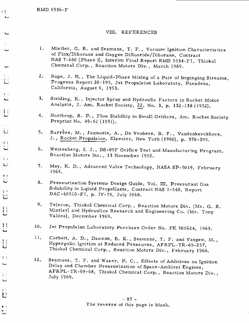
RMD 5536-F
VIII. REFERENCES
: 7
i!
| ]
| _:
2
Z
Io
_o
3_
.
.
.
.
8_
,
I0.
iI.
IZ.
Mistier, G. R. and Seamans, T. F., Vacuum Ignition Characteristics
of Flox/Diborane and Oxygen Difluoride/Diborane, Contract
NAS 7-660 (Phase I), Interim Final Report RMD 5534-FI, Thiokol
Chemical Corp., Reaction Motors Div., March 1969.
Rupe, J. H. , The Liquid-Phase Mixing of a Pair of Impinging Streams,
Progress Report 20-195, Jet Propulsion Laboratory, Pasadena,
California, August 6, 1953.
Stehling, K., Injector Spray and Hydraulic Factors in Rocket Motor
Analysis, J. Am. Rocket Society, 22, No. 3, p. 132-138 (195Z).
Northrup, R. P. , Flow Stability in Small Orifices, Am. Rocket Society
Preprint No. 49-51 (1951).
Barr_re, M., Jaumotte, A., De Veubere, B. F., Vandenkerckhove,
J., Rocket Propulsion, Elsevier, Ne_ York (1960), p. 370-395.
Weisenberg, I. J., DS-89F Orifice Test and Manufacturing Program,
Reaction Motors Inc., 13 November 1952.
May, K. D., Advanced Valve Technology, NASA SP-5019, February
1965.
Pressurization Systems Design Guide, Vol. III, Pressurant Gas
Solubility in Lqiuid Propellants, Contract NAS 7-548, Report
DAC-60510-F1, p. IV-75, July 1968.
Telecon, Thiokol Chemical Corp., Reaction Motors Div. (Mr. G. R.
Mistier) and Hydraulics Research and Engineering Co. (Mr. Tony
Valdez), December 1969.
Jet Propulsion Laboratory Purchase Order No. FK 505624, 1969.
Corbett, A. D., Dawson, B. E., Seamans, T. F. and Vanpee, M.,
Hypergolic Ignition at Reduced Pressures, AFRPL-TR-65-257,
Thiokol Chemical Corp., Reaction Motors Div., February 1966.
Seamans, T. F. and Waser, P. C., Effects of Additives on Ignition
Delay and Chamber Pressurization of Space-Ambient Engines,
AFRPL-TR-69-68, Thiokol Chemical Corp., Reaction Motors Div.,
July 1969.
- 87 -
The reverse of this page is blank.

II
I •
I •
m
I
_m
II
l
mm
um
[]m
ID

iJ
w
L ,
L_
RMD 5536-F
APPENDIX A
INJEC TOR DRAWINGS
A-1

i
_+__
i
i
a
a
i
I
I
i
+ []I
-- z
,iiml
: [
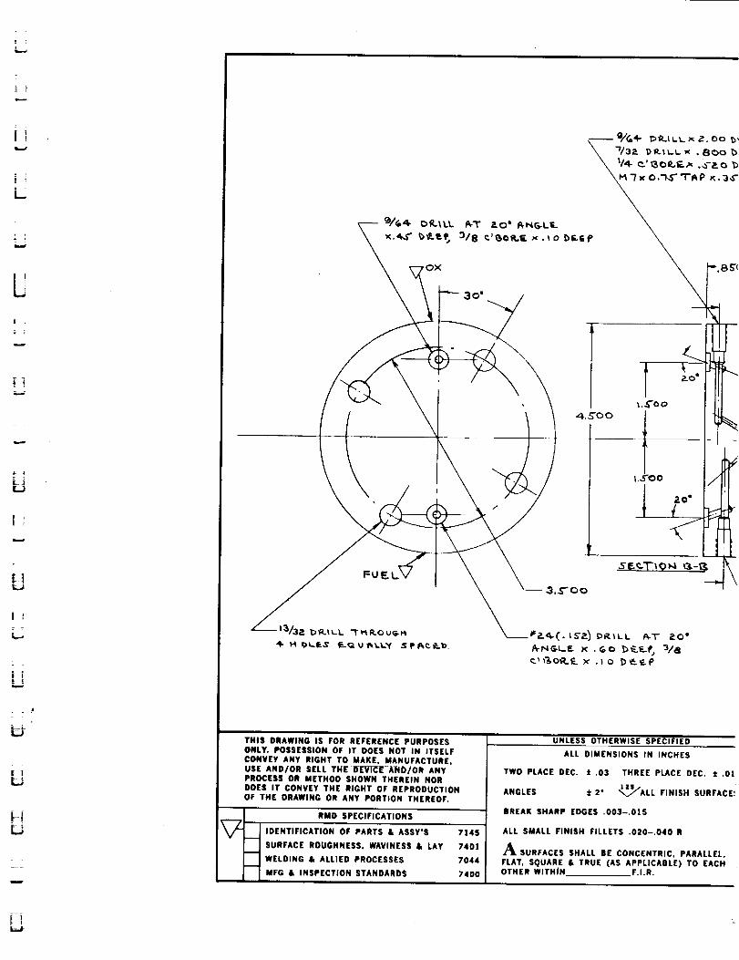
U
u
THIS DRAWING IS FOR REFERENCE PURPOSESONLY. POSSESSION OF IT DOES NOT IN ITSELF
CONVEY ANY RIGHT TO MAKE. MANUFACTURE,USE AND/OR SELL THE OLrVl_l_ AND/OR ANYPROCESS OR METHOD SHOWN THEREIN NORDOES IT CONVEY THE RIGHT OF REPRODUCTIONOF THE DRAWING OR ANY PORTION THEREOF.
i_ RMD SPECIFICATIONS
IDENTIFICATION OF PARTS & ASSY'S 7145
SURFACE ROUGHNESS, WAVINESS & LAY 7401
WELDING & ALLIED PROCESSES 7044
MFG & INSPECTION STANDARDS 7400
UNLESS OTHERWISE SPECIFIED
ALL DIMENSIONS IN INCHES
TWO PLACE DEC. :1: .03 THREE PLACE DEC. :1:.Ol
ANGLES ::IL2" "_/ALL FINISH SURFACE!
BREAK SHARP EDGES .003-.015
ALL SMALL FINISH FILLETS .O2O-.O4O R
A SURFACES SHALL BE CONCENTRIC, PARALLEL,
FLAT, SQUARE /, TRUE (AS APPLICABLE) TO EACHOTHER WITHIN F.I.R.

I
E
I
W
II
qii
LL_
Ful
I
W
I
II
IN
U
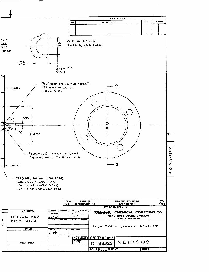
NlrVlllONll
OI|¢IIIPTION
F_E_
DF..F..P
.ce8• o'/e
o- e-tNG. G _._vE.
_)_..T_,tt..Io x ,SiT.E-
©
©
MATERIAL
N t_._t_ I_ _ O0
_TM I_lGo
FINISH
HEAT TREAT
ITEM I PARTO, INO. l IDENTIFYING NO.
O_AWN C_¢CK_m M_V |_*rF rams
F.l, _les _N_m |_. svmmss
NIL NO
Ssa,_
Nmm-r *:sv. _m_e.
' IiRMD CLASS
NOMENCLATURE ORDESCRIPTION
J QTYREQO
LIST OF MATERIALS
_, CHEMICAL CORPORATIONREACTION MOTORS DIVISION
DENVILL[. NEW JENII[Y
I i'_,.) "E.e_,T 0 if., - ..3 | NG LE b (_ U fl I.E..T"
SiZE CODE IDENT
C 83323 x__no,_ o__
SCALE_1 WEIGHT I SHmET
4--
i
i
×P.70
0
i

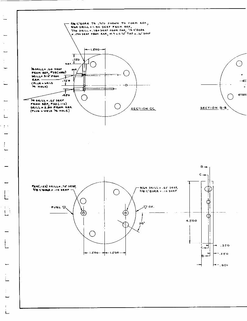
iu.,.
|L..
t
©
.ff

U
Q=_
U
m_m
rl
um
ml
kl
m
im
ill
m
rail
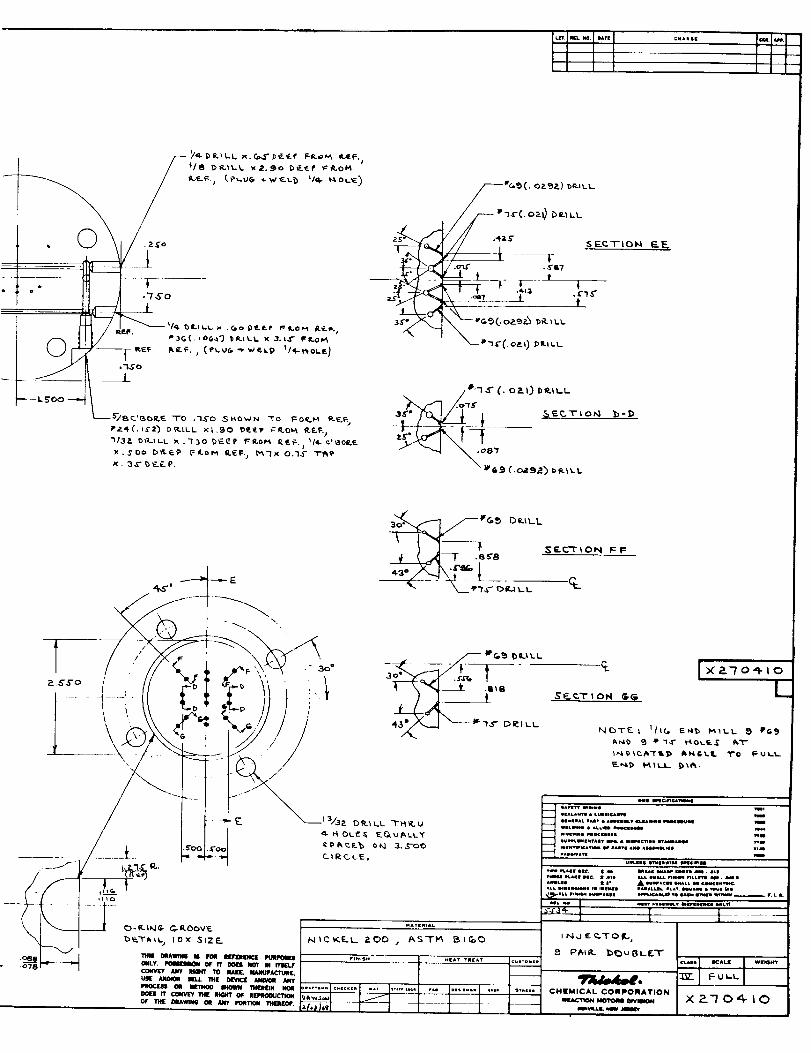
<
/_--- w l_(, o:_t)Oe._LL
.o-_C .s's7
__I_L___ ;__ _t
*'_(. o,.0 D_-iLL
"_ r""l /.o'_$
//

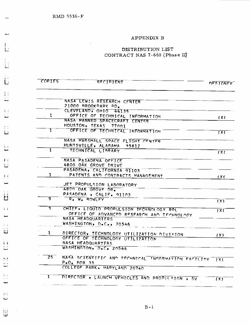
RMD 5536-F
APPENDIX B
DIS TRIBU TION LIS T
CONTRACT NAS 7-660 (Phase Ill
R_CTPT_NT D_TGNFr
= =
= =
- i
1
NASA LEWIS RESEARCH CFNTER
21000 _ROOKPARK PD,
CLE_ , 35
OFFICE OP TECHNICAL INFORMATIONNASA MANNED SPACECPAFT CENTER
HOUSTON, TEXAS 77001
OFFICE OF TF_HNICAL INFORMATION
(X(
(X(
Z ]
NASA _ARSHALL SmACF FLIGHT C=NTF_HUNTSVTLLE_ ALABAMA _5812
1 TECHNICAL LIBRARY (X(
NASA PASADENA OFFICF4800 OAK GROVE DRIVE
PASADENA, CALIFORNIA 91103
1 PATENTS _N_ ?ONTPaCTS MANAG_MFNT {X(
U
JFT PROPULSION LABORATOPY
PASADENA 9 CALIF, _]lh3
9 R, W, ROWLFY (X)
CHIEF, LIQUID PROPULSION TRCHNOLOGY RDL (X(
OFFICE OF ADVANCmD R_SFARCH ANm TCrHNOI._GY
NASA HEADQUARTERS
r •
WASHINGTON. D,C,, 20546
1 DIRECTOR, TECHNOLOGY UTILIZATION _!VICION (X)OFFICE OF TECHNOLOGY UTILIZATION
NASA HEADQUARTERS
WA.KHINGTON, D,C° 2.n.5_6
----_-5......N-A_-ASCI_-NTI_Ir---AN _ T_C_HNTcA.L !NCh_M_TIC_N _ACTI I_Y
P,O, ROX _(X)
CO[LFG_ PARK, MARYLAND 207_0
l DIRFCTOR , LAUNCH VEHICLES AND PROPI" CTC3N , SV (X)
B-I

= =I
W
u
i
[]
g
im
D
II
Ll
U
hm
: =
u
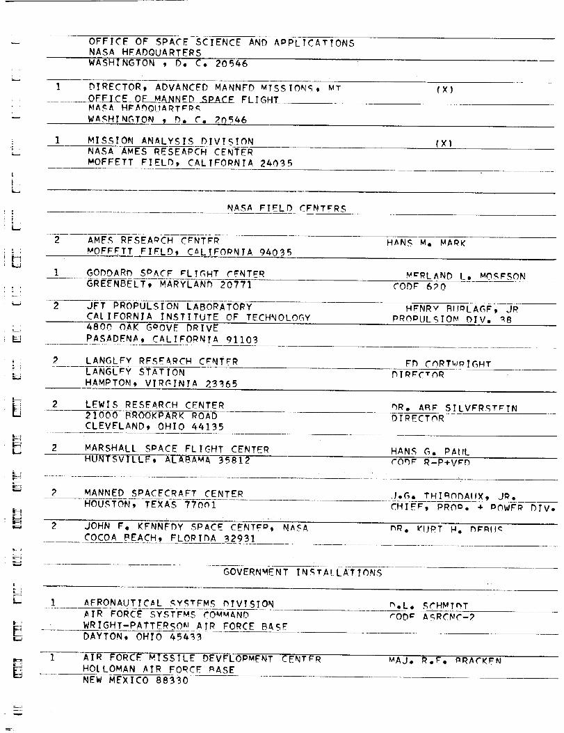
OFFICE OF SPACE SCIENCE AND APPLICATIONSNASA HFADQUARTERSWASHINGTON , D, C. 205k6
1 DIRECTOR9 ADVANCED MANNFD MISSIONg_ MT {X)
__OFFiCE_OF MA_ED__P_A_CE__LIGH_
NASA H_A_OUART_PS
WASHINGTON _ D. C, 20546
I MISSION ANALYSIS DIVISION {X}F NASA AMES RESEARCH CENTER
MOFFETT FIELD, CALIFORNIA 240_5
| ,
L
NASA FIELD CFNT_'RS
2 AMES RFSEAmCH C_NTFR HANS m, MA_K
MOFFFTT FIFLD_ CALIFORNIA 940_5
GODDARD SPACF _LTGHT ?_NTER Y:RLAND L, MOg_SON
'-iGREENBELT, MARYLAN_ 20??] CODE 6_0
2 JFT PROPULSION LABORATORY
CA{ IFORNIA INSTITUTE OF TECHNOLOGYHFNRV F_I_LAG_ .JR
PRC)PULSIOKt {)IV, _B
4800 OAK G_OVE DRIVE
PASADENA, CALIFORNIA 91103
2 LANGLFY RFSEARCH CENTER FD ChRT_.tPIGHT
LANGLEY STATION
HAMPTON_ VIRGINIA 23365DIRECTOR
2 LEWIS RESEARCH CENTER _R, ARE SILVFR%T_TN
21000 BROOKPARK ROAD
CLEVELAND_ OHIO 44135
DIRECTOR
F_
2 _ARSHALL SPACE FLIGHT CENTER HANS G. PAIIL
HUNTSV]_C-L--E%__ ALABAMA 35812 CO_r R-P+VCD
\
2 MANNED SPACECRAFT CENTER .I,G, T_I_O_AIIX, J_,
HOUSTON_ TEXAS ??Oh1 CHIE¢_ PRO_, + DOWF# bfV,
2 JOHN F, KENNEDY SPACE CENTER, NASA mR, _UPT H, m_mlc
COCOA PEACH_ FLORIDA 32931
GOVERNMENT INSTALLATIONS
] AFRONAUTIC_L _YSTFMS _IVISION m.L, SCHMImT
AIR FORCE SYSTEMS COMMAND rOD_ ASRCNC-2
WRIGHT-PATTERSOm AIR FORCE BASE
DAYTON, OHIO 45_33
t_
_Jr_
! •
AIR FORCE MISSILE DEVFLOPMFNT CENTER
HOtLOMAN AIR FORCE mASE
NEW MEXICO 88330
MAJ. _.E. _RACK_N

1 AIR FORCE MISSILE TEST CENTFRPATRICK AIR FORCE BASE, FLORIDA
[.J. !ILLIAN
i
I
SPACE AND MIS_IL_ SYSTEMS ORG.ANIZ_TI_!
AIR FORCF UNIT DOST OFFICE
LOS ANGELES 459 CALIFORNIA 9C)C)45
COL, CLA_
T_CHNIrAL hSTA
CENT_!_il
1 ARNOLD ENGINeeRING DFVFLOmMEKIT C_N_P
ARNOLD AIR FORCE STATION
TULLAHOMA, TENNESSEE 37388
OR. Ho_, h_TSC_
ii
-i BUREAU OF NAVAL WEAmONS
DEPARTMENT OF THE NAVY
WASHINGTON t D, C. 20546
CAMERON STATION, BUILDING
ALEXANDRIA, VIPGINTA 22_14ATTN-_
NE_-UA_-ERS, U.S. _I__
WASHINGTON 25, D.C. 20546
COL.C.K. _TAM_AUGH
AFRST
I
I
ii
PICATINNY ARSENAL
IZTO_;_-JER_EY 07801
I. FORSTEN, CHIEF
LIQUIh PRhmJL£ION
LABORATORY, u
2 AIR FORCE ROCKet P_OPIILqlhN LAbORATOrY RmRo_I_R. _. MAIN
RFSFARCH ANh T_CHNmLOGY DIVISION
AIR FORCE _YSTFMS COMMAND
EDWARDS, ¢ALIFO--_N]T-_3_9
--] .......U._. ARMY MISSILE Cd_'_
REDSTONE AeSENAL
AL ABe-3 5-8-0g-
MR. WALTER WHARTON
I
I
[]
CHINA LAKE
CAt I-FO-RN IA 9___57
COnE A562
CHIFF_ _I_cTLF
_ROPI!LSInN DIV.
II
CPIA-
CHEMICAL PROPULSIO_ INFORMATION _GE_rY TOM REEDY
APPLIE0 PHYSICS LABORATORY
8621 GEORGIA AVENU_ "
_ILVER SPRING, MSRYLAND 209]0
i
IiI
INDUSTRY CONT o ACTORS
[]
II
L.
1 AFRO JET-GENERAL CORPOI_ATIC_N W, L, I_OG_.SP, O, ROX 296AZU.qA_ CALIFORNIA 9]?03
1 AFROJFT-GENFPAL COmPORATI_N _, STIFF
P, O, _OX ]947
TECHNICAL LIBRARY+ BLhG 2_1_, DebT, ?_1_
SACRA_NTO_ CALIFORNIA 95809
] SPACE DiViSION _. MA£_LA_._KI
9200 EAST FLAIR DR, " " " ' '
EL MONTEt CALIFORNIA 91734+:
1 AEROsPAC_ CORPORATION JOHN G. WILDER
240n FAST EL _EGLIN_O BOULEVARD MS-220_
P. O, _OX 95h85
LO_ ANGELEs, CALIFORNIA _0h45
II
k2
ASTROSYSTEMS INTrRNATIONAL_ INC.1275 BLOOMFIEL_ AVeNUe
FAIRFIFL.h_ N_W JFRSY n?OO?
Ao _FNnENHALi_
i . ATLANTIC RESEARCH CORPORATION _R, RAY FRIEDMAN
............FDSALL ROAD AND SHIRLFY HIGHWAY
ALEXANDRIA, VIRGINIA 22314
AVCO SYSTEMS DIVISION HOWARD B, "WIN_LFR
WILMINGTON_ _A_SACHUS_TTS
BEECH AIRCRAFT CORPORATION J, H° _ODG_RS
_OtILDER OIVISIhN
BOX 63]
BOULDER _ COLORADO
BELL AFROSYSTE_S COMPANY W° M° SMITH
,_=+.P,O, BOX I
_UFFALO_ NEW YORK 1_2k0
i- 1
1 H, _, LONDON_FLt COMM. _.
P AZA, S. W.I_AKHINC-TON_ D. C.
I _ENDIX SYST___S DIVISION JOHN M, Bm_FGF_
__FNDIX CORPORATItnN
33r)0 PLYMOI.ITH ROAD • .
ANN ARBOR, MICHIGAN 48105
I <BOE'IN__ANY J, D. A]_-EXANDER
P, O. BOX 3707 .... ' '
._FATTL_, WASHINGTON q812_+= + , ?
] BOEING COMPANY t IBRARY
1625 K ST_F_Tt No _o
WASHINGTC)N_ D, C, ?OOn6
1 I_OrING COMI_ANY .... TED _NthV!
P° O, _OX 168n ' "
r,
= .=
L_
HUNTSVILLEt ALABAMA 35801

MISSILF DIVISION MR, JOlaN C_ATES
CHRYSLER CORPORATION
P. O. _OX #628DETROIT, MTCNIGAN 48231
-_ .......W R[GRT AERONAUTICAL DIVISION
CURTTSS-WRTGHT CORPORATION
WOOD-RIDGE, NEW JERSFY n7075
_* K_'L I.FY
RESEARCH CFNT_R RALPH _ALL
FAIRCHILD HILLER CORPORATION
GFRUANTOWN, MAmYLAND
REPUBLIC AVIATION CORPORATION
FAIRCHIED HILLER CORPORATION
FARMINGDAL_, LONG TSLANh, N_W YOP_
I IBRARV
GFNFRAL DYNAMICS, (,ONVAIR mIVISION
LIBRARY + IN_Om_AT?ON SFRVTC_ (!_@-hn}
_RAN_ mOP_
P, O, BOX 112B
1 M-I-_S_E AND SPACE _YST_MS C_NTER
GENERAL _L_CTRIC COMPANY---- VA_T_O3Tc_rs_A_TErT_C__Y CENTER
P°O, BOX 8555PHILADELPHIA, PA_
F, MEZ_ER
F, Z. SCHULTZ
-] GRUMMAN--/_CI_CRAFT-_ERING CO_m. JOS_mM GAV?N
BETHPAGE, LONG T_LAND
_R, GOmDON HAP_
NFW YOPK ]17!4
] HON'EYWFL L, IN(',
AEROSPACE_ _IV°
26nn RIDAWAY Rr)MINNEAPOLIS, MINN,
] HUGHES AIRCRAFT CO, E, H,_ MEIER 'AFROSPAC.F_ GROUP V,P,ANm DIV, M GR°,CENTIN_LA AND T_'AL_" STI_F_T_ I_E_ARCH 4- r_v, r_Iv°
CUtVFR CITY, CALIF, ()O.21_0
]. WAITER KIIbD_. ANt_ COMPANY, INC, _', J, HANVTLL_.
A__ROSPACF OPF_ATIONS DIR° hF RF_ARCH CNGm°
567 MAIN STREET
_EtLEVILL_ N_Fw JERSEY
1 .......LI NG_i'-EMco-V/3UGHT CC)-RPORA-TIt3N-
P° O° BOX 5907
WARREN G, TRFNT
DAtLAS, T_XAS _6222
] ARTHUR D, LITTLE, INC, LIBRARY
20 ACORN PAR_ . :. _ .=:_............... CA_PRI_G_-. MASSA-CHUSETTS 02140
] LOCKHEED MISSILrS AND SPACE CQ, J. GUILLATTN-T_CHNICACYNFORMATION (,_NT_R .. ,,
P,O, BOX 504
,,m
J
i
m
gm
U
Nm
I
SUNNY-VA---LE-9--CA-[-IF'OR_I i A 9 4 0 8 8
LOCKHEED PROPULSION COMPANY H. L, THACKWFLL
P. O, _OX 111
REDLANDS, CALIFC_PNIA 923T4
THE MAROUARDT CORPORATION
]6555 SATICOY _TPE_T
VAN NUYS _CALIF, 91409
HOWARD MC RARLAND
] RA[TIMORF DIVISION MR, JOHN CALATH_5 (_21AMARTIN MARIETTA CORPORATION
BAITIMORE, MARYLAND 21203
l DENVER DIVISION hR MOR_ANTHALER
MARTIN MARIETTA CORPORATION 8. J, KULLASPe O, _OX 179
DENVER, COLORADO 8n201
]. OR[ ANDO DIVISION J. _rR_
MARTIN MARIETTA COPP,
BOX 5837OR[ ANDO, FLOPIDA
1 A_TROPOWER LAmOPATORY hR. GRORGR MOC
MC DONNELL-DOUGLAS AIRCRAFT COMOANY DIR_CTnR, _ESFARCH
21_I PAULAPINO=
NEWPORT BEACH, CALTFOPNIA 92663
l MCDONN_L-DOU_LAS AIRCRAFT CORD. P.A. H_R/_ARKP. O, BOX 516
MUNICIPAL AIRPORT
ST, LOUIS_ MISSOURI 6_]66
] MIS_ILF AND SPACE SYSTEMS DIVISION MR, R, W, HALL_T
MC DONNELL-DOUGLAS AIPCRAFT COMPANY CHIEF ENGINEER
3000 OCEAN PARK BOULEVARD ADV, SPACE TECH.
SANTA MONICA, CALIF. 90406
1 SPACE+INfORMATION SYSTEMS DIVISION LIBRARY
NOPTH AMERICAN POC_WELL
]221_ LAKEWOOD BOULEVARD
DOWNEY, CALIFORNIA 90241
! - :
- TL_.
ROCKETDYNE (LIBRARY 586-306)
6639 CANOGA AVENUE S;:F..*TIAcoR_CLI_CANOGA PARK, CALIF, 91B04 ......
1 NORTHROP SPACE L_BORATOPIES _R, WILLIAU HOWARD'
_4nI WEST BROADWAY
HAWTHORNE, CALIFORNIA 90250 _ "
I AERONUTRONIC DIVISION h.A. GAPPI_ON
PHIl_CO CORPORATIONFORD RnAD
NEWPORT BEACH, CALIFORNIA 92663

I
1 ASTPO-_LECTRONICS DIVISION Y. BRILLRADIO CORPORATION OF AMERICA
PRINCETON_ NEW JERSEY 08540
ROCKET RESEARCH CORPORATION FOY IulCCULLnUGHt JR.520 SOUTH PORTLAND STPFFT
SEATTLF, WASHINATON 98]08
%UN_TRAND AVIATION P, W, _FYN_LDS7421 IITH STREFT
ROCKFORD, ILLINOIS 61101
I _TANFORD R_SFARCH INSTITHT_ _R, A_RALD MARKSMAN3S3 RAVFNSWOOD AVENU_
MENLO PARK, CALIFORNIA g4025
TRW ROUPT-_W_NC_-_ONF SPACE PARKREDONDO BEACH_ CALIF,
YAPC_nIV_STON
TRW, INCORPORATED
23555 EUCLID AVFNUF
CLFVFLAND, OHIO 44117
90278
1 THIOKOL CHEM'ICAL CORPORATION
-UI-IO-NT.KV-ILLEDIVISION
HUNTSVILLE, ALABAMA 358_7
P. T. ANG_LL
RESEARCH LABORATORIES
UNITED AIRCRAFT CO_P,
400 MAIN ST,FAST HARTFORD, CONN. 06108
JOHN _nODLOE
HAMILTON STANDARD OIVISON
UNITED AIRCRAFT CO_P.
WIND£OR LOCKS9 CONN. 060Q6
FRL_ MAPTIN
UNITED T_CH_I_I_Or_Y CENTER
MR, R, HATCH
587 _ETHILDA AV_NU_Po O, ROX _SB
_UNNYVALE_ CALIFORNIA 94_R8
DR, DAVID ALTMAN
] FLORIDA RESEARCH AND DEVELOPHENT
PRATT AND WHITNEY AIRCRAFT
P. O, _OX 2.69] ..... _........ :WE_T PALMREACH_ FLORIDA 33402 ........
R,Jo C_AR
I VICKER_ !NC,
_OX 3n?............TR_ MI_HI_AN
i
I
i
II
i
F
I +
IIiI+
UI
-==-
I
L_-- ---
5-_ ++
m+l
I! ¸
.:+