Embed Size (px)
Citation preview
RESEARCH INTO ADVANCED CONCEPTS
OF MICROWAVE POWER AMPLIFTCATTON
AND
GENERATION UTTLIZTNG LINEAR BEAM DEVICES
CASE FlCE COPY
School of Electrical Engineering
Cornell University
Semiannual Status Report
December 1969
Research Grant NGL 33-010-047 No. 2
National Aeronautics and Space Administration
Electronics Research Center
Cambridge, Massachusetts
ABSTRACT
This i s an i n t e r i m r e p o r t which summarizes work
d u r i n g t h e p a s t s i x months on a t h e o r e t i c a l s t udy of
some a s p e c t s of t h e i n t e r a c t i o n between a d r i f t i n g s t ream
o f e l e c t r o n s w i t h t r a n s v e r s e c y c l o t r o n motions and an
e l ec t romagne t i c f i e l d . P a r t i c u l a r emphasis i s g iven t o
the p o s s i b l e g e n e r a t i o n and a m p l i f i c a t i o n of m i l l i m e t e r
waves. The r e p o r t i n c l u d e s a d i s c u s s i o n of t h e r e s u l t s
o f a d i g i t a l computer s t udy of t h e s t a r t o s c i l l a t i o n con-
d i t i o n s f o r a s p i r a l i n g f i l a m e n t a r y e l e c t r o n beam i n a
c a v i t y and some of t h e conc lus ions t h a t can b e drawn
from t h i s s t udy .
TABLE OF CONTENTS
ABSTRACT
PAGE
If
I. INTRODUCTION ' 1.
11. START OSCILLATION CONDITIONS FOR A
SPIRALING FILAMENTARY ELECTRON BEAM TN A CAVITY 2
A. Introduction 2
B. Start Oscillation Conditions 5
C. Conclusions 16
REFERENCES
iii
I. ENTRODUCTTON 0
The objective of this research program is to explore
theoretically some aspects of the interaction between
a drifting stream of electrons having transverse cyclo-
tron motions and zn electromagnetic field; particular
emphasis being given to the possible generation and ampli-
fication of millimeter waves. Because of the interest in
possible applications to millimeter wavelengths, this
study .concentrates on electron stream-electromagnetic
a field interactions which involve an uniform, or fast-wave,.
circuit structure.
This interim report discusses the start oscillation
conditions for the interaction between a spiraling fila-
mentary electron beam and a rectangular cavity of square
cross section. Using the computational procedure outlined
in the previous Semiannual Status ~ e ~ o r t l and the Cornell
IBM/360 digital computer, the start oscillation conditions
for a range of electron beam and cavity parameters were
obtained. These results are summarized and briefly analyzed
in this report.
11. START OSCILLATION CONDITIONS FOR A SPIRALTNG
FILAMENTARY ELECTRON BEAM I N A CAVITY
A . I n t r o d u c t i o n
A small s i g n a l , coupled mode theo ry f o r t h e i n t e r -
a c t i o n between a s p i r a l i n g f i l a m e n t a r y e l e c t r o n beam and
t h e c i r c u i t waves of an uniform waveguide has been developed
and d i s c u s s e d i n p rev ious Semiannual S t a t u s Repor t s . 2
This theory has been a p p l i e d t o determining t h e s t a r t
o s c i l l a t i o n c o n d i t i o n s f o r a s p i r a l i n g f i l a m e n t a r y e l e c t r o n
beam i n a r e c t a n g u l a r c a v i t y o f square c ros s s e c t i o n . A
computat ional procedure was developed t o use t h e Corne l l
IBM/360 d i g i t a l computer t o o b t a i n numeri.ca1 r e s u l t s f o r
t h e s t a r t o s c i l l a t i o n c o n d i t i o n s .' The numerical r e s u l t s
f o r t h e s t a r t o s c i l l a t i o n c o n d i t i o n s f o r a range of e l e c t r o n
beam and c a v i t y paramete rs a r e summarized and d i s cus sed i n
t h i s r e p o r t .
The model used t o r e p r e s e n t t h e o s c i l l a t o r has two
major components: t h e c a v i t y and t h e e l e c t r o n beam. The
c a v i t y i s t aken t o be a r e c t a n g u l a r parallelepiped wi th a
square c r o s s s e c t i o n and copper w a l l s . Loss due t o t h e
f i n i t e c o n d u c t i v i t y of t h e copper walls i s t a k e n i n t o account
i n t h e computat ions . The e l e c t r o n beam i s assumed t o be
f i l amen ta ry and t o be s p i r a l i n g around t h e a x i s of t h e
c a v i t y a s it d r i f t s i n t h e presence of an a x i a l d-c magnetic
f i e l d . The o s c i l l a t o r ou tpu t s i g n a l i s t aken from t h e end

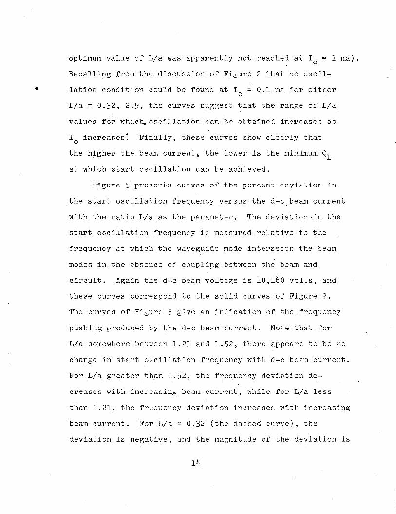
of the cavity at which the electron beam enters; see Figure
1. It is assumed that the electron beam interacts with
the TEIOl and TEOll modes of the cavity.
The significant cavity parameters are its length L
and width a, together with its loss and output coupling.
The cavity loss and coupling will be expressed, as usual,
in terms of Qo and 9,. The significant electron beam
parameters are the d-c beam voltage Vo, the d-c beam current
I09 the axial d-c magnetic flux density Bo, the d-c axial
drift velocity io, the d-c angular velocity Bo, and the d-c
beam radius ro. It should be recalled that relativistic
effects have been included in the analysis and are important
for the interaction between a spiraling filamentary electron
beam and a cavity.
As discussed in the previous Semiannual Status Reports 2
the interaction involves six waves; four electron beam
waves and two circuit waves. The procedure used to deter-
mine the start oscillation conditions is to consider the
device as a one-port amplifier and calculate the gain of
the device for a given set of electron beam and cavity
parameters. A set of parameters which leads to infinite
gain corresponds to a start oscillation condition for the
device. To use the computer to determine the start oscil-
lation conditions, all the cavity and electron beam
parameters are fixed except the cavity coupling parameter
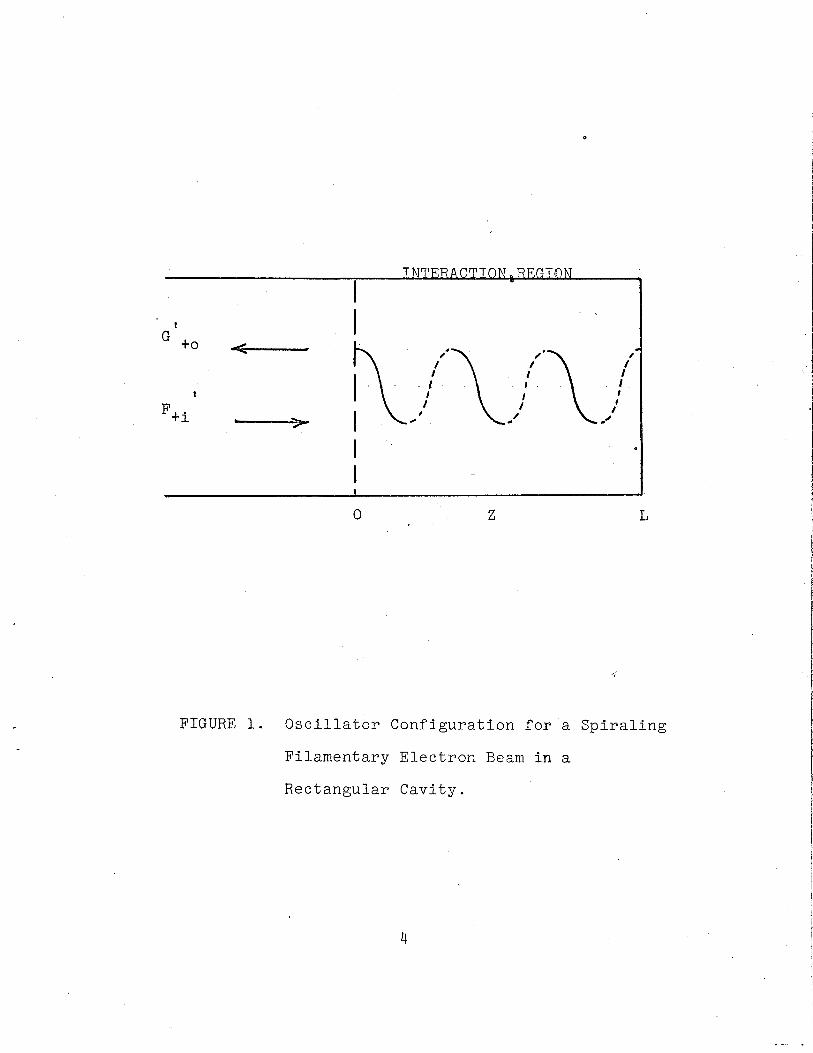
FIGURE 1. Oscillator Configuration for a Spiraling
Filamentary Electron Beam in a
Rectangular Cavity.
Qx and t h e o p e r a t i n g f requency f s . These two paramete rs ,
Qx and f s , a r e t hen a d j u s t e d u n t i l a p o l e i n t h e g a i n i s
ach ieved ( a c t u a l l y , a v o l t a g e g a i n g r e a t e r t h a n 100 has
been cons idered s u f f i c i e n t ) ; a t t h a t p o i n t , t h e s e t o f
paramete rs corresponds t o a s t a r t o s c i l l a t i o n c o n d i t i o n .
B . S t a r t O s c i l l a t i o n Condi t ions
The s ta r t o s c i l l a t i o n c o n d i t i o n s f o r a range of e l e c t r o n
beam and c a v i t y paramete rs have been c a l c u l a t e d . Most of
t h e c a l c u l a t i o n s , however, were f o r a s i n g l e v a l u e of d-c
e l e c t r o n beam v o l t a g e Vo and c a v i t y c r o s s s e c t i o n .
S p e c i f i c a l l y , t h e normal ized d-c a x i a l and angu la r d r i f t *
v e l o c i t i e s were t aken t o be: o = z0/c = 0.01, and
5 = w r / C = 0.20, where w c = eBo/m i s t h e n o n - r e l a t i v i s t i c C 0
c y c l o t r o n frequency; t h e s e correspond t o a d-c e l e c t r o n beam
v o l t a g e of Vo = 10,160 v o l t s . The c a v i t y width and h e i g h t
were t aken t o be 1.6655 cen t ime te r s ; t h i s cor responds t o a
cu to f f f requency i n squa re waveguide of 9.00 GHz f o r t h e
TEIO and TEOl modes. I n a l l c a s e s a l o s s f a c t o r f o r t h e
c a v i t y a p p r o p r i a t e f o r copper w a l l s has been assumed.
The o s c i l l a t o r paramete rs which a r e e a s i e s t t o vary
i n t h e l a b o r a t o r y a r e no t n e c e s s a r i l y t h o s e which a r e most
convenient t o vary i n a computat ional p rocedure . Tn t h e
c a l c u l a t i o n of t h e s ta r t o s c i l l a t i o n c o n d i t i o n s , i t i s most
convenient t o ho ld bo th t h e c a v i t y l e n g t h L and t h e d-c
magnetic f l u x d e n s i t y Bo f i x e d whi le t h e s e a r c h f o r t h e
i n f i n i t e g a i n ~ a i n t i s c a r r i e d o u t . However, f o r a g iven
B t h e r e i s only a narrow range of L va lues f o r which 0
o s c i l l a t i o n can be achieved. Based on publ i shed d a t a f o r
o p e r a t i n g dev i ce s , b u t admi t t ed ly r a t h e r a r b i t r a r i l y , t h e
c a v i t y l e n g t h L was chosen t o be a h a l f guide wavelength a t
a f requency one p e r c e n t above t h e r e l a t i v i s t i c c y c l o t r o n
f requency; t h a t i s , a t a f requency e q u a l t o 1 . 0 1 nu,. Most
o f t h e s t a r t o s c i l l a t i o n d a t a were ob t a ined f o r t h i s cho ice
o f t h e c a v i t y l e n g t h . This c a v i t y l e n g t h i s no t n e c e s s a r i l y
t h e optimum va lue , and a l i m i t e d amount of d a t a ob t a ined
f o r o t h e r c a v i t y l e n g t h s i n d i c a t e s t h a t i t i s no t t h e optimum.
However, t h e major t r e n d s i n t h e d a t a ob ta ined and t h e con-
c l u s i o n s t h a t can be drawn from them a r e be l i eved t o be
v a l i d even though t h e combination of c a v i t y l e n g t h and
magnetic f i e l d used may no t be t h e optimum va lue .
F i n a l l y , i n a l l c a se s t h e ou tpu t c i r c u i t was assumed
t o p r e s e n t a r e s i s t i v e l oad t o t h e o s c i l l a t o r . That i s , i t
was assumed t h a t t h e r e i s no r e a c t i v e ( o r energy s t o r a g e )
element a s s o c i a t e d w i th t h e ou tpu t coupl ing of t h e o s c i l l a t o r .
F igu re 2 p r e s e n t s curves o f t h e d-c beam c u r r e n t I.
v e r s u s t h e loaded c a v i t y QL f o r s t a r t o s c i l l a t i o n . The
d i f f e r e n t curves a r e f o r d i f f e r e n t r ' a t ios of c a v i t y l e n g t h
t o width, L/a. Assoc ia ted w i th each va lue of L/a i s a
p a r t i c u l a r va lue of t h e r e l a t i v i s t i c cyc lo t ron f requency
n w c , a d j u s t e d so t h a t t h e c a v i t y l e n g t h i s equa l t o a h a l f
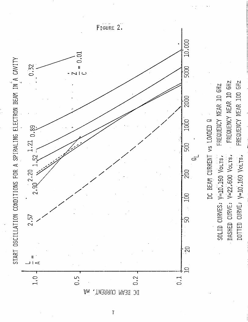
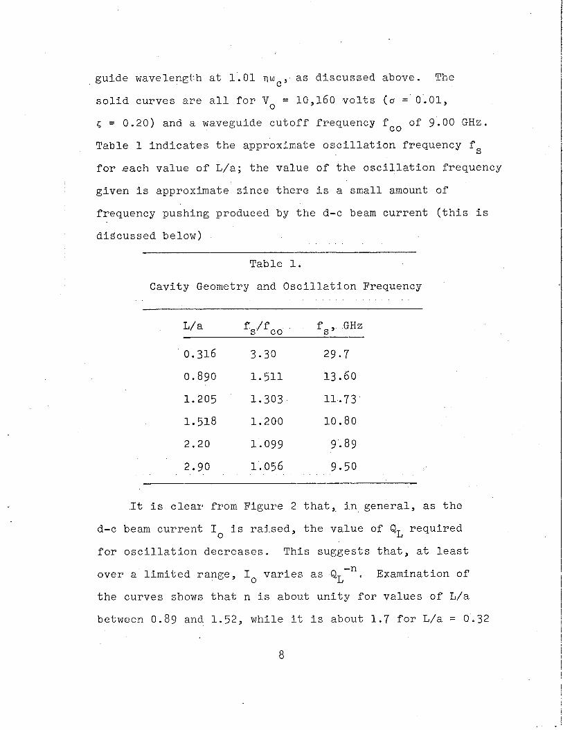
guide wavelength a t 1 . 0 1 q u c , a s d i s cus sed above. The
s o l i d curves a r e a l l f o r Yo = 10,160 v o l t s ( o = 0.01,
5 = 0.20) and a waveguide c u t o f f f requency f c o of 9.00 G H z .
Table 1 i n d i c a t e s t h e approximate o s c i l l a t i o n f requency f s
f o r e a c h v a l u e o f L/a; t h e va lue of t h e o s c i l l a t i o n f requency
g iven i s approximate s i n c e t h e r e i s a smal l amount of
f requency pushing produced by t h e d-c beam c u r r e n t ( t h i s i s
d i s cus sed below)
Table 1.
Cavi ty Geometry and O s c i l l a t i o n Frequency
L/a f s / f co f s , GHZ
It i s c l e a r from F igu re 2 t h a t , i n gene ra l , as t h e
d-c beam c u r r e n t I. i s r a i s e d , t h e v a l u e of QL r e q u i r e d
f o r o s c i l l a t i o n d e c r e a s e s . Th is sugges t s t h a t , a t l e a s t
-n over a l i m i t e d range , I. v a r i e s a s QL Examination of
t h e curves shows t h a t n i s about u n i t y f o r va lues of L / a
between 0.89 and 1 .52 , whi le i t i s about 1 . 7 f o r L/a = 0.32
and dec rease s t o 0.46 a t L/a = 2 . 9 . Although n = 0.77
f o r t h e L/a = 2.2 curve shown, o t h e r d a t a f o r a more n e a r l y
optimum magnetic f i e l d a t t h i s L/a r a t i o y i e l d a va lue o f
n nea r u n i t y . Thus one can conclude t h a t over a range of
paramete rs t h e d-c s t a r t o s c i l l a t i o n beam cu r r en t v a r i e s
-1 approximately as QL . . I n F igu re 2 t h e curves f o r L/a = 0.32, 2.9 a r e t e rmina t ed
a t I. = 0.5 m a because no o s c i l l a t i o n could be found a t
I. = 0 .1 m a , t h e nex t lower beam c u r r e n t i n v e s t i g a t e d . No
a t tempt was made t o vary t h e magnetic f i e l d s l i g h t l y t o s e e
i f o s c i l l a t i o n s could be ob t a ined a t t h e 0.1 ma l e v e l by
op t imiz ing t h e magnetic f i e l d . Because of t h e f i n i t e c a v i t y
l o s s , t h e r e w i l l be a minimum d-c beam c u r r e n t below which no
o s c i l l a t i o n s can be ob t a ined r e g a r d l e s s of op t imiz ing t h e
magnetic f i e l d ; no a t t empt was made t o e s t a b l i s h t h i s
minimum c u r r e n t l e v e l f o r o s c i l l a t i o n .
The d o t t e d curve on F igu re 2 was c a l c u l a t e d f o r a
c u t o f f f requency f c o = 90.0 GHz ( a = 1.6655 mm). The very
s l i g h t d i f f e r e n c e between t h i s curve and t h e cor responding
curve f o r f co = 9.00 GHz i s probably due t o t h e i n c r e a s e d
c a v i t y l o s s a t t h e h ighe r f requency . Data were ob t a ined
only f o r I. = 1 . 0 and 0.5 m a , bu t t h e r e i s no r ea son t o
b e l i e v e t h e curves would d i f f e r s i g n i f i c a n t l y a t 0 . 1 ma.
The almost exac t correspondence between t h e s e two curves
which d i f f e r by a f a c t o r of t e n i n frequency, sugges t s
t h a t t h e d a t a ob t a ined h e r e f o r f c o = 9.00 GHz can be
s c a l e d f o r u s e %hroughout t h e microwave range and t h e l onge r
m i l l i m e t e r wavelength range w i t h reasonable accuracy .
The dashed curve i n F igu re 2 (L/a = 2.57) corresponds t o
a d-c beam v o l t a g e of 22,600 v o l t s ( a = 0.01, 5 = 0 .30) .
The g e n e r a l t r e n d o f t h i s curve i s s i m i l a r t o t h o s e f o r t h e i
lower beam v o l t a g e , bu t t h e d-c beam c u r r e n t r e q u i r e d f o r
s t a r t o s c i l l a t i o n f o r a g iven QL i s reduced. This beam has
the ' same a x i a l d r i f t v e l o c i t y bu t a h i g h e r angu la r v e l o c i t y
t h a n t h e p rev ious beam. For a g iven a x i a l d r i f t v e l o c i t y
t h e r e may be an optimum angu la r v e l o c i t y t o g i v e a minimum
s t a r t o s c i l l a t i o n c u r r e n t f o r f i x e d QL; no a t t empt was made
t o determine t h i s .
A b r i e f i n v e s t i g a t i o n was made of t h e e f f e c t s of
vary ing t h e a x i a l d r i f t v e l o c i t y a t f i x e d angu la r v e l o c i t y ,
5 = 0.20. It was found t h a t a t a d-c beam c u r r e n t of 1 . 0 ma,
i n c r e a s i n g a t o 0.02 caused t h e s t a r t o s c i l l a t i o n QL t o
i n c r e a s e by a f a c t o r of about f i v e f o r L/a = 2.2; whi le a t
o = 0.03, no o s c i l l a t i o n cou ld be found. Th i s sugges t s
t h a t t h e s t a r t o s c i l l a t i o n c o n d i t i o n i s r a t h e r s e n s i t i v e t o
t h e a x i a l d r i f t v e l o c i t y , and t h a t t h e o s c i l l a t i o n can
e x i s t only f o r ve ry low a x i a l d r i f t v e l o c i t i e s ( r e l a t i v e
t o t h e v e l o c i t y o f l i g h t ) .
F igure 3 p r e s e n t s curves of t h e d-c s t a r t o s c i l l a t i o n
beam c u r r e n t I. v e r s u s QL f o r Vo = 10,160 v o l t s , L/a = 2.2
and t h r e e va lues of t h e d-c magnetic f i e l d . The t h r e e
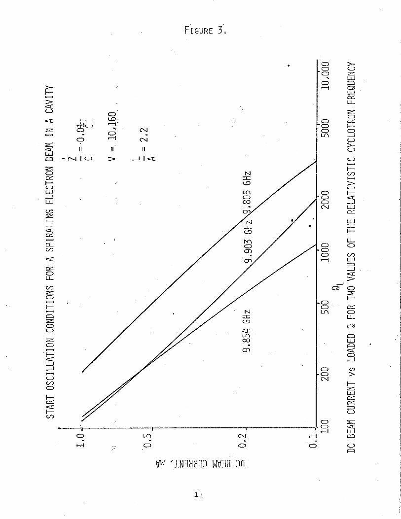
curves are labcled with the relativistic cyclotron
frequency (neBo/2nm) associated with the magnetic field used.
The curve for 9.805 G H z is the one which appears on Figure 2.
It was also determined that no oscillation occurred in
this' range of beam current for a relativistic cyclotron
frequency of 9.756 G H z . Clearly the optimum magnetic field
for this ratio of L/a is one yielding a relativistic
cyclotron frequency in the neighborhood of 9.854 G H z . The
general trends of the three curves shown are similar; this
is regarded as justification for accepting the conclusions
drawn from Figure 2 where data were used which may not in-
clude the optimum magnetic field values. There is some
change in oscillation frequency as the magnetic field is
varied at fixed d-c beam current. However, the percent change
in oscillation frequency is always less than the percent
change in the relativistic cyclotron frequency, and this
percentage chafige in oscillation frequency decreases with
decreasing d-c beam current.
Figure 4 presents curves of L/a versus QL at start
oscillation, with the d-c beam current I. as the parameter.
Again the d-c beam voltage Vo = 10,160 volts, and these
curves correspond to the solid curves of Figure 2. These
curves indicate that for each value of d-c beam current
there is an optimum value of L/a at which QL is a minimum
for start oscillation. The curves suggest that this
optimum value of L/a increases as I incremes (the 0
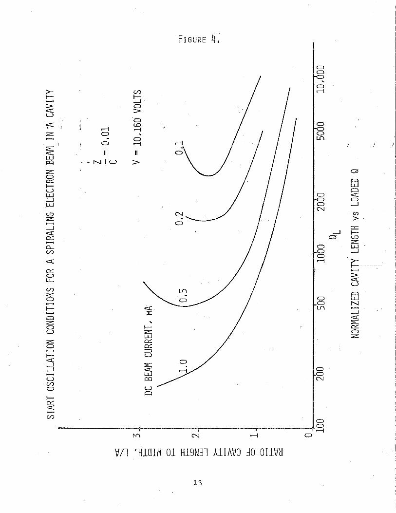
optimum v a l u e of L/a was a p p a r e n t l y no t reached a t To = 1 ma).
R e c a l l i n g from t h e d i s c u s s i o n of F igu re 2 t h a t no o s c i l -
l a t i o n c o n d i t i o n could be found a t To = 0 .1 ma f o r e i t h e r
L/a = 0.32, 2 .9 , t h e curves sugges t t h a t t h e range of L/a
va lues f o r ~ h i c h ~ o s c i l l a t i o n can be ob ta ined i n c r e a s e s as
I. increases : F i n a l l y , t h e s e curves show c l e a r l y t h a t
t h e h i g h e r t h e beam c u r r e n t , t h e lower i s t h e minimum QL
a t which s t a r t o s c i l l a t i o n can be achieved.
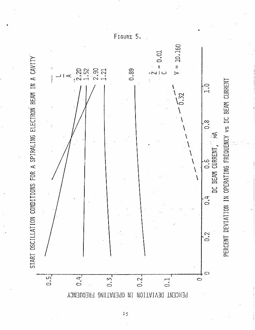
F igu re 5 p r e s e n t s curves o f t h e pe rcen t d e v i a t i o n i n
t h e s ta r t o s c i l l a t i o n f requency v e r s u s t h e d-c beam c u r r e n t
w i t h t h e r a t i o L/a as t h e paramete r . The d e v i a t i o n - i n t h e
s t a r t o s c i l l a t i o n f requency i s measured r e l a t i v e t o t h e
f requency a t which t h e waveguide mode i n t e r s e c t s t h e beam
modes i n t h e absence of coupl ing between t h e beam and
c i r c u i t . Again t h e d-c beam v o l t a g e i s 10,160 v o l t s , and
t h e s e curves correspond t o t h e s o l i d curves of F igu re 2 .
The curves of F igu re 5 g i v e an i n d i c a t i o n of t h e f requency
pushing produced by t h e d-c beam c u r r e n t . Note t h a t f o r
L/a somewhere between 1 . 2 1 and 1 .52, t h e r e appears t o be no
change i n s t a r t o s c i l l a t i o n f requency wi th d-c beam c u r r e n t .
For L/a g r e a t e r t h a n 1.52, t h e f requency d e v i a t i o n de-
c r e a s e s w i t h i n c r e a s i n g beam c u r r e n t ; whi le f o r L/a l e s s
t h a n 1 .21, t h e frequency d e v i a t i o n i n c r e a s e s w i t h i n c r e a s i n g
beam c u r r e n t . For L/a = 0.32 ( t h e dashed c u r v e ) , t h e
d e v i a t i o n i s n e g a t i v e , and t h e magnitude of t h e d e v i a t i o n i s
PERCENT DEVIATION IN OPERATING FREQUENCY
shown. The curves suggest that one could choose an optimum
value for L/z if it was desired to minimize the frequency
pushing produced by the d-c beam current.
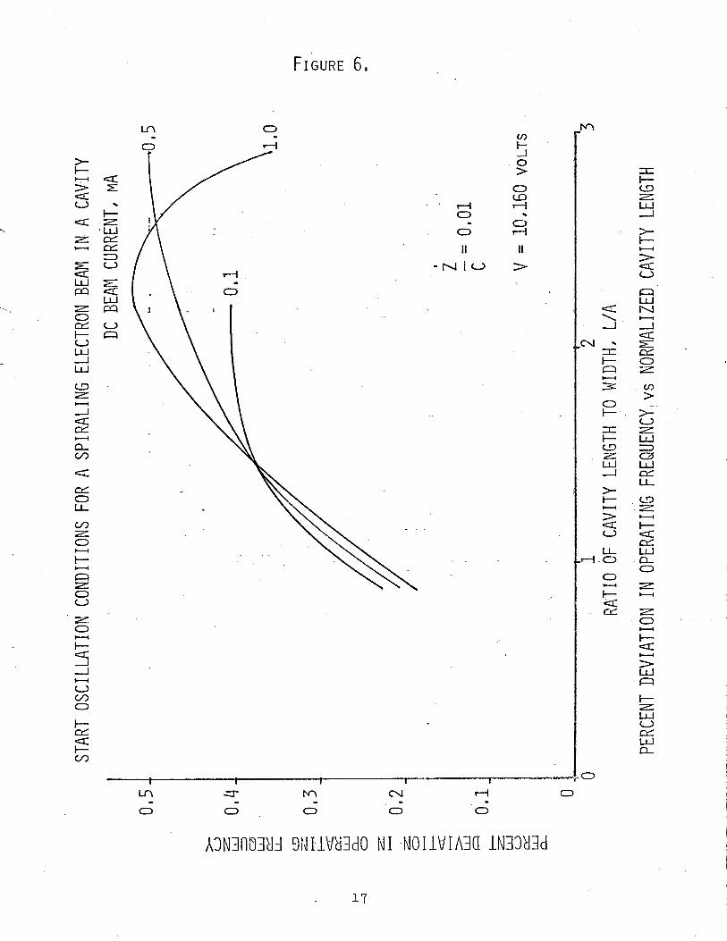
Figure 6 presents curves of the percent deviation in
the start oscillation frequency versus L/a with the d-c
beam current as the parameter. The three curves cross in
the neighborhood L/a = 1.45 indicating that this is the
optimum value of L/a to minimize the frequency pushing
produced by the d-c beam current for the beam and cavity
parameters investigated here. There is some indication
from the curves that as a function of L/a, the percent
deviation in the start oscillation frequency passes through
a maximum, with the maximum increasing with increasing beam
current.
C. Conclusions
Several of the conclusions developed in the course
of the discussion of the previous section are summarized here.
1. The d-c beam current (for fixed d-c beam voltage,
d-c magnetic field, and cavity dimensions) required
for start oscillation varies inversely with QL. Over
a range of beam and cavity parameters, the start
oscillation beam current varies nearly linearly with
l/QL*
2. Most of the data discussed in this report are based on
a particular cavity width and height (1.6655 cm).
16
However, these results should be applicable and scale
directly throughout the microwave and the longer
millimeter wavelength ranges,
3. For given cavity dimensions, the optimum start oscil-
lation conditions (that is, the minimum QL for a given
d-c beam current) are a sensitive function of the d-c'
magnetic field.
4. For each value of d-c beam current, there is an optimum a
value of L/a which minimizes QL at start oscillation.
This value of L/a increases as the d-c beam current
increases. In other words, as the d-c beam current
is increased, the start oscillation frequency fs at
optimum L/a (minimum QL) more nearly approaches the
cutoff frequency fco of the waveguide.
5. The start oscillation frequency fs can either increase
or decrease with increasing d-c beam current, depending
on the L/a ratio used. There is an optimum value of
L/a for which the start oscillation frequency is in-
dependent of the d-c beam current, at least over a
range of current.
REFERENCES
1. P . R . McIsaac, Semiannual S t a t u s Repor t , NASA
Research Grant NGR 33-010-047, No. 2 , J u l y 1969.
2. P . R . McIsaac, Semiannual S t a t u s Repor t s , NASA
Research Grant NGR 33-010-047, December 1967, June
1968, and December 1968.