Embed Size (px)
Citation preview

»Zone Offroad Products • 491 W. Garfield Ave., Coldwater, MI 49036 • 888.998.ZONE • www.zoneoffroad.com
Read and understand all instructions and warnings prior to installation of product and operation of vehicle.Zone Offroad Products recommends this system be installed by a professional technician. In addition to these instructions, profes-sional knowledge of disassembly/ reassembly procedures and post installation checks must be known. Minimum tool requirements include the following: Assorted metric and standard wrenches, hammer, hydraulic floor jack and a set of jack stands. See the "Special Tools Required" section for additional tools needed to complete this installation properly and safely.
»Product Safety Warning
Certain Zone Suspension Products are intended to improve off-road performance. Modifying your vehicle for off-road use may result in the vehicle handling differently than a factory equipped vehicle. Extreme care must be used to prevent loss of control or vehicle rollover. Failure to drive your modified vehicle safely may result in serious injury or death. Zone Offroad Products does not recom-mend the combined use of suspension lifts, body lifts, or other lifting devices.
You should never operate your modified vehicle under the influence of alcohol or drugs. Always drive your modified vehicle at re-duced speeds to ensure your ability to control your vehicle under all driving conditions. Always wear your seat belt.
»technical SuPPort
Live Chat provides instant communication with Zone tech support. Anyone can access live chat through a link on www.zoneoffroad.com .
www.zoneoffroad.com may have additional information about this product including the lat-est instructions, videos, photos, etc.
Send an e-mail to [email protected] detailing your issue for a quick response.
888.998.ZONE Call to speak directly with Zone tech support.
»Pre-inStallation noteS
1. Special literature required: OE Service Manual for model/year of vehicle. Refer to manual for proper disassembly/reassembly procedures of OE and related components.
2. Adhere to recommendations when replacement fasteners, retainers and keepers are called out in the OE manual.
3. Larger rim and tire combinations may increase leverage on suspension, steering, and related components. When selecting combi-nations larger than OE, consider the additional stress you could be inducing on the OE and related components.
4. Post suspension system vehicles may experience drive line vibrations. Angles may require tuning, slider on shaft may require replacement, shafts may need to be lengthened or trued, and U-joints may need to be replaced.
5. Secure and properly block vehicle prior to installation of Zone Offroad Products. Always wear safety glasses when using power tools.
6. If installation is to be performed without a hoist, Zone Offroad Products recommends rear alterations first.
7. Due to payload options and initial ride height variances, the amount of lift is a base figure. Final ride height dimensions may vary in accordance to original vehicle attitude. Always measure the attitude prior to beginning installation.
rev110314
C9157 Installation Instructions2015 Chevy Colorado/GMC Canyon1.5" Body Lift
Difficulty Leveleasy 1 2 3 4 5 difficult
Estimated installation: 4 hours
Special Tools Required4.5" Cut off wheel
Torx socket set
Tire/Wheel Fitment265/65/R17
C9157 Installation - pg. 2
Kit ContentsQty Part
8 3" Diameter body block8 2" Diameter body block2 Front Bumper Bracket1 Lower Facia Bracket - Drv1 Lower Facia Bracket - Pass1 Rear Bumper Bracket - Drv1 Rear Bumper Bracket - Pass1 Parking Brake Bracket1 Bumper Step Spacer2 Steel Bed Spacer1 Loctite2 8-3/8 x 18 Zip Tie
1 Bolt Pack 284 8 14mm x 140mm bolt
8 12mm x 70mm bolt
8 9/16" SAE flat washer
8 1/2" SAE flat washer
1 Bolt Pack 285 2 3/8"-16 x 3/4" bolt
4 3/8"-16 x 1" bolt
14 3/8" SAE washer
6 3/8"-16 lock nut
2 10mm x 30mm flat head bolt
2 10mm x 30mm SHCS
1 7/16"-14 x 1" bolt
2 7/16" SAE washer
1 7/16-14" lock nut
2 5/16"-18 x 1/2" self-tapping bolt
INSTALLATION INSTRUCTIONS1. Park the vehicle on a clean, flat surface and block the rear wheels for safety.
2. Disconnect the positive and negative battery cables.
3. Disconnect the clips holding the electric harness located behind the driver's side inner fender and above the front cab body mount to gain adequate slack.
4. Disconnect the ground wire located on the top of the frame rail near the front of the driver side inner fender well.
5. Make an indexing mark on the steering shaft and disconnect it to prevent bind-ing during the body lift procedure. Ensure the steering wheel is not turned while disconnected.
»front faScia diSaSSembly
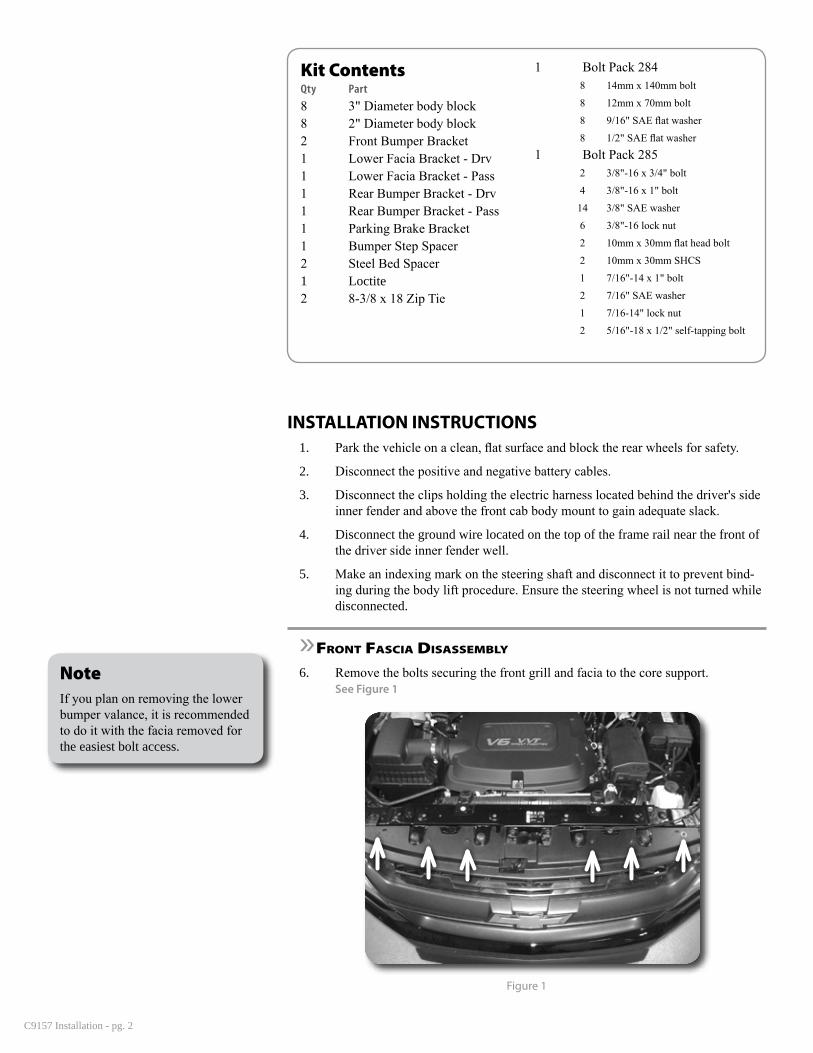
6. Remove the bolts securing the front grill and facia to the core support. See Figure 1
Figure 1
NoteIf you plan on removing the lower bumper valance, it is recommended to do it with the facia removed for the easiest bolt access.
C9157 Installation - pg. 3
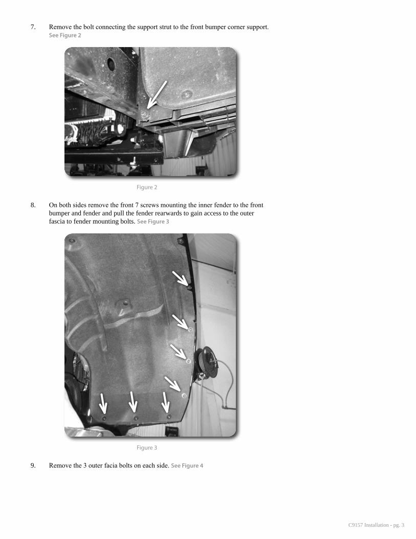
7. Remove the bolt connecting the support strut to the front bumper corner support. See Figure 2
Figure 2
8. On both sides remove the front 7 screws mounting the inner fender to the front bumper and fender and pull the fender rearwards to gain access to the outer fascia to fender mounting bolts. See Figure 3
Figure 3
9. Remove the 3 outer facia bolts on each side. See Figure 4

C9157 Installation - pg. 4
Figure 4
10. Disconnect the fog lights
11. Remove the 2 screws on the bottom of the facia mounting to the frame on each side of the front splash guard.
12. Remove the 2 center fascia mounting bolts. See Figure 5
Figure 5
13. Gently pull out on the front fascia near the inside lower corner of the headlights to release the clips and remove the facia from the vehicle.
14. Remove the 2 bolts per side mounting the front crash bar to the frame. See Figure 6
Figure 6

C9157 Installation - pg. 5
»Parking brake bracket
15. Locate the parking brake running along the driver side frame rail. Take a measurement or mark on the cable, the current brake adjustment based on the amount of threads showing past the adjustment nut. See Figure 7
Figure 7
16. Remove the nut and disconnect the parking brake at the rear distribution block.
17. Using a flat screwdriver release the clips holding the parking brake cable to the body mount on the frame.
18. Remove the cable from the body mount and relocate the cable above the frame.
19. Measure down from the center of the OE cable hole on the body mount 3/4" and drill a 3/8" hole at the mark.
20. Install the parking brake bracket with the provide 7/16" hardware so the tab in the bracket lines up with the drilled hole.
21. Clip the cable to the hole in the bracket and route it through the center body mount similar to original setup and reconnect the cable at the distribution block. Adjust the cable to the setting previously measured.
»cab lift
22. Starting on the passenger side, remove the 3 cab mount bolts and 1 front core support mount bolt. Loosen but do not remove the driver side bolts.
23. Remove the large factory washers from the bolts and place them on the provided 14mm x 140mm bolt with washers.
24. Place a jack with a block of wood to distribute the load near the front cab mount, in a reinforced area of the body and lift the body just high enough to place the provided 3" diameter body blocks between the OE mount and the body.
25. Apply Loctite to the new bolts and thread them a few turns into the body.
26. Lower the jack and remove the bolts from the driver side. Raise the driver side and make sure there is adequate slack on all wires and cables as the body is lifted.
27. Install the remaining cab bolts with the factory washers and Loctite. Lower the jack and torque all cab bolts to 100 ft-lbs.
Step 23 NoteCab mount hardware is located in bolt pack 284.
Step 24 NoteEnsure there is adequate slack in all cables are wires as the body is lifted.
C9157 Installation - pg. 6
»bed lift
Ensure the cab lift procedure is performed before raising the bed to avoid any interfer-ence between the bed and the body.
28. Remove the 4 bed mount bolts on the passenger side of the vehicle. Loosen but do not remove the driver side bolts.
29. Locate the jack towards the passenger side on one of the bed supports and raise the bed enough to install the 2" diameter body lift pucks at each location.
30. Apply Loctite and loosely install the provided 12mm x 70mm bolts and washers at the bed mounts.
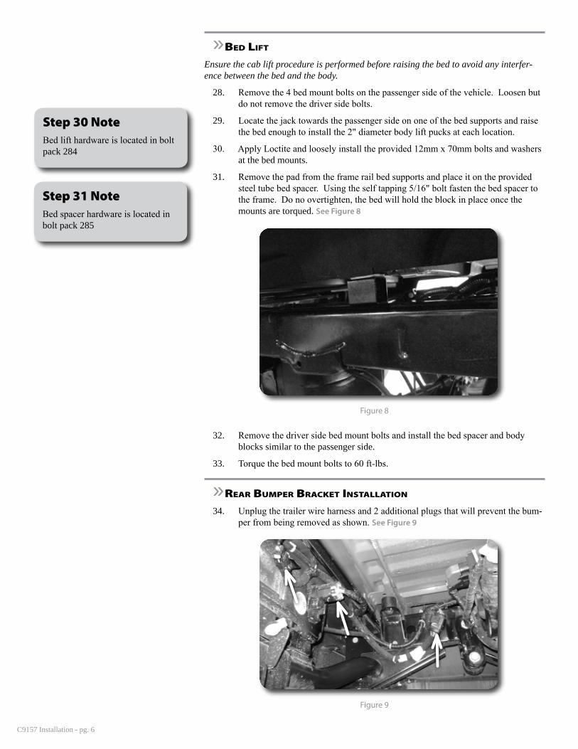
31. Remove the pad from the frame rail bed supports and place it on the provided steel tube bed spacer. Using the self tapping 5/16" bolt fasten the bed spacer to the frame. Do no overtighten, the bed will hold the block in place once the mounts are torqued. See Figure 8
Figure 8
32. Remove the driver side bed mount bolts and install the bed spacer and body blocks similar to the passenger side.
33. Torque the bed mount bolts to 60 ft-lbs.
»rear bumPer bracket inStallation
34. Unplug the trailer wire harness and 2 additional plugs that will prevent the bum-per from being removed as shown. See Figure 9
Figure 9
Step 30 NoteBed lift hardware is located in bolt pack 284
Step 31 NoteBed spacer hardware is located in bolt pack 285

C9157 Installation - pg. 7
35. Remove the 2 bolts on the outside of each frame rail and slide the bumper off of the vehicle.
36. Release the clips on the bumper cover enough to access the bolts to the bumper brackets. Remove the bumper brackets from the bumper by removing the 6 bolts. See Figure 10
Figure 10
37. Remove the factory U-nuts from the factory brackets and transfer them to the provided brackets. See Figure 11
Figure 11
38. Install the new bumper brackets in place of the factory brackets using the factory hardware. Tighten bolts to 60 ft-lbs. See Figure 12
Figure 12

C9157 Installation - pg. 8
39. Place the provided step spacer above the factory hitch. The slots cut in the tube face up and towards the front of the vehicle. See Figure 13
Figure 13
40. Fasten the step spacer to the hitch with the provided 3/8" x 3/4" bolts, nuts, and washer using the outermost holes.
41. Re-install the bumper onto the frame using the factory bolts. Ensure the spare tire winch tubes line up while sliding on the bumper. Torque the bolts to 60 ft-lbs.
42. Reconnect the wire harness and clips disconnected for the bumper removal.
»front faScia inStallation
43. On both sides, using the new front bumper brackets as a template, cut the mate-rial shown in the figure from the frame. Also drill a 7/16" hole at the inside bracket mounting hole. See Figure 14
Figure 14
44. Using the provided 10mm flat head bolt in the outside upper hole and the socket head bolt in the lower hole, attach the bumper brackets to the frame. See Figure 15
Step 40 NoteBed Step hardware is located in bolt pack 285
C9157 Installation - pg. 9
Figure 15
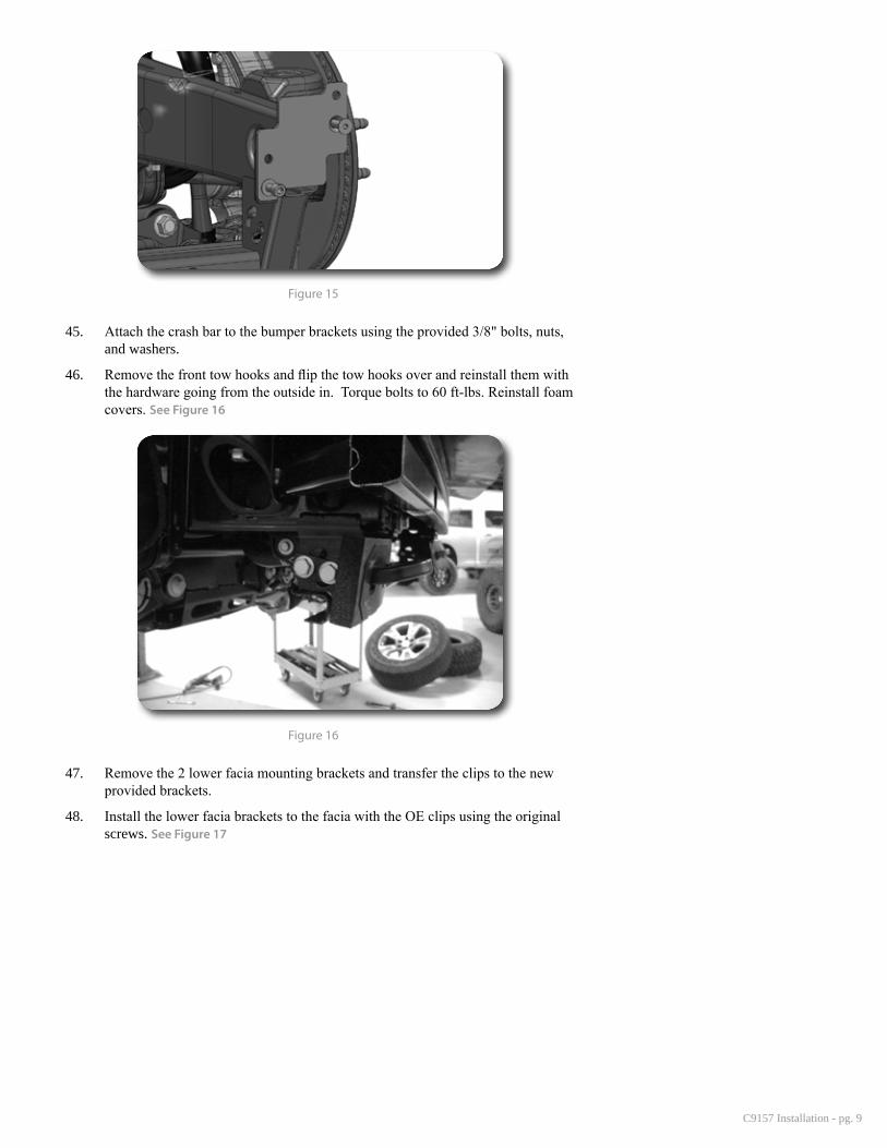
45. Attach the crash bar to the bumper brackets using the provided 3/8" bolts, nuts, and washers.
46. Remove the front tow hooks and flip the tow hooks over and reinstall them with the hardware going from the outside in. Torque bolts to 60 ft-lbs. Reinstall foam covers. See Figure 16
Figure 16
47. Remove the 2 lower facia mounting brackets and transfer the clips to the new provided brackets.
48. Install the lower facia brackets to the facia with the OE clips using the original screws. See Figure 17

C9157 Installation - pg. 10
Figure 17
49. Install the facia back onto the vehicle first by engaging the clips located near the lower inside corner of the headlights.
50. Reinstall the 3 bolts connecting the fender to the fascia on each side.
51. Reinstall the 2 center bolts removed in step 12.
52. Install the original lower bolts through the new lower facia brackets into the frame.
53. Reinstall the inner fender screws.
54. Reinstall the outer support brace bolts.
55. Reinstall the 6 top screws mounting the grill to the core support.
»final StePS
56. Reconnect the ground strap at the driver side frame rail. It may be necessary to permanently release it from a retaining clip to gain enough slack.
57. Reconnect the steering sector shaft using the factory bolt and Loctite. Torque the bolt to 45 ft-lbs.
58. Using the supplied wire ties, attach the electrical harness to the parking brake bracket and frame rail. Re-use the OE mounts as shown. See Figure 18
Figure 18

C9157 Installation - pg. 11
59. Reconnect the battery.
60. Double check all hoses, wires, cables, etc for proper slack and routing.
61. Check all hardware for proper torque.
62. Check for proper tire clearances.
63. Check hardware after 500 miles.