Embed Size (px)
Citation preview
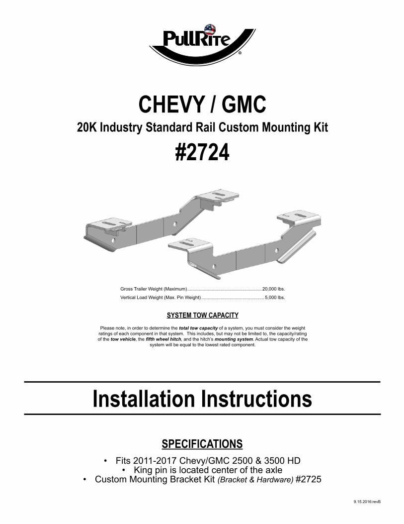
SPECIFICATIONS• Fits 2011-2017 Chevy/GMC 2500 & 3500 HD
• King pin is located center of the axle• Custom Mounting Bracket Kit (Bracket & Hardware) #2725
9.15.2016:revB
Installation Instructions
CHEVY / GMC20K Industry Standard Rail Custom Mounting Kit
#2724
Gross Trailer Weight (Maximum) ..........................................................20,000 lbs.
Vertical Load Weight (Max. Pin Weight) .................................................5,000 lbs.
SYSTEM TOW CAPACITYPlease note, in order to determine the total tow capacity of a system, you must consider the weight
ratings of each component in that system. This includes, but may not be limited to, the capacity/rating of the tow vehicle, the fi fth wheel hitch, and the hitch’s mounting system. Actual tow capacity of the
system will be equal to the lowest rated component.
2 #2724 Custom ISR Installation Instructions (9.15.2016:revB)
TABLE OF CONTENTS
CONTENTS
PLATE ASSEMBLY................................................................................................................................ 3
MOUNTING KIT EXPLODED VIEW ...................................................................................................... 4
MOUNTING KIT PARTS LIST ............................................................................................................... 5
TRUCK PREPARATION ........................................................................................................................ 6
MARKING THE TRUCK BED FOR DRILLING ...................................................................................... 6
LAYOUT METHOD ........................................................................................................................ 6
TEMPLATE METHOD ................................................................................................................... 7
INSTALLATION ..................................................................................................................................... 8
PART 1 — BRACKET PLACEMENT & BED HOLE LOCATIONS ............................................... 8
PART 2 — BRACKET INSTALLATION ........................................................................................ 9
PART 3 — SHIMMING THE BED .............................................................................................. 10
PART 4 — FINAL INSTALLATION PROCEDURES .................................................................. 10
#2724 Custom ISR Installation Instructions (9.15.2016:revB) 3
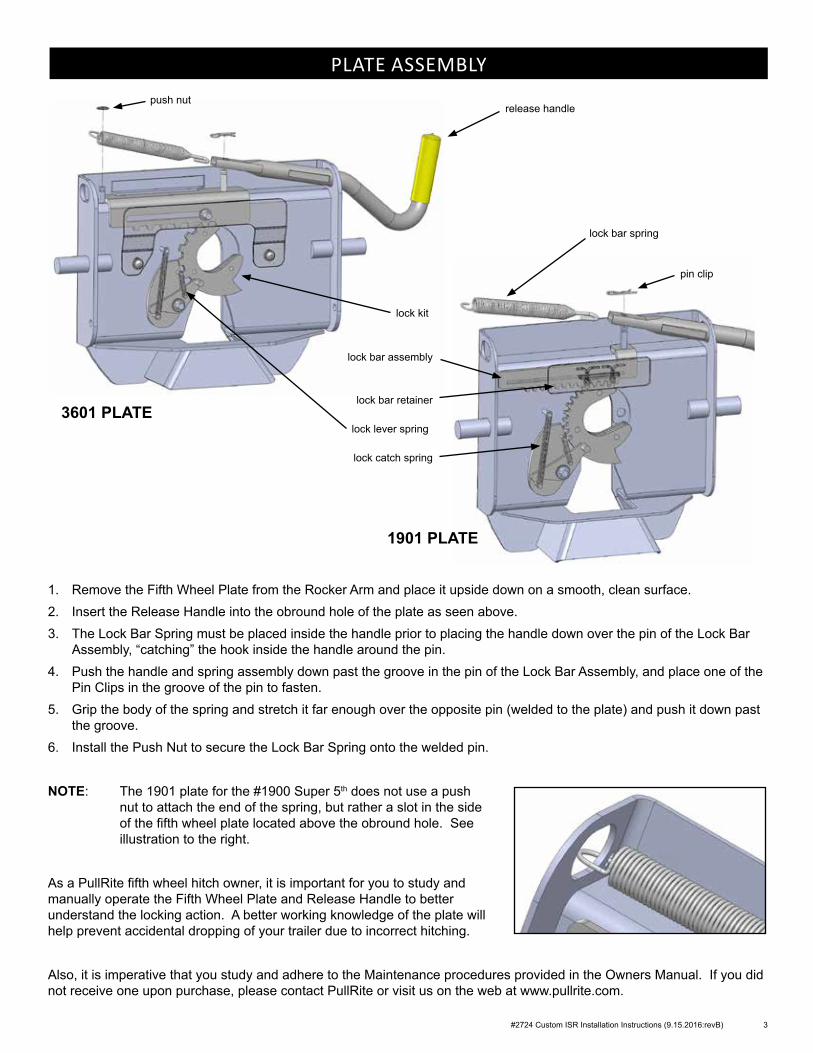
PLATE ASSEMBLY
1. Remove the Fifth Wheel Plate from the Rocker Arm and place it upside down on a smooth, clean surface.2. Insert the Release Handle into the obround hole of the plate as seen above.3. The Lock Bar Spring must be placed inside the handle prior to placing the handle down over the pin of the Lock Bar
Assembly, “catching” the hook inside the handle around the pin.4. Push the handle and spring assembly down past the groove in the pin of the Lock Bar Assembly, and place one of the
Pin Clips in the groove of the pin to fasten.5. Grip the body of the spring and stretch it far enough over the opposite pin (welded to the plate) and push it down past
the groove.6. Install the Push Nut to secure the Lock Bar Spring onto the welded pin.
NOTE: The 1901 plate for the #1900 Super 5th does not use a push nut to attach the end of the spring, but rather a slot in the side of the fifth wheel plate located above the obround hole. See illustration to the right.
As a PullRite fifth wheel hitch owner, it is important for you to study and manually operate the Fifth Wheel Plate and Release Handle to better understand the locking action. A better working knowledge of the plate will help prevent accidental dropping of your trailer due to incorrect hitching.
Also, it is imperative that you study and adhere to the Maintenance procedures provided in the Owners Manual. If you did not receive one upon purchase, please contact PullRite or visit us on the web at www.pullrite.com.
lock bar spring
3601 PLATE
pin clip
release handlepush nut
lock bar assembly
lock catch spring
lock bar retainer
lock kit
lock lever spring
1901 PLATE
4 #2724 Custom ISR Installation Instructions (9.15.2016:revB)
LB
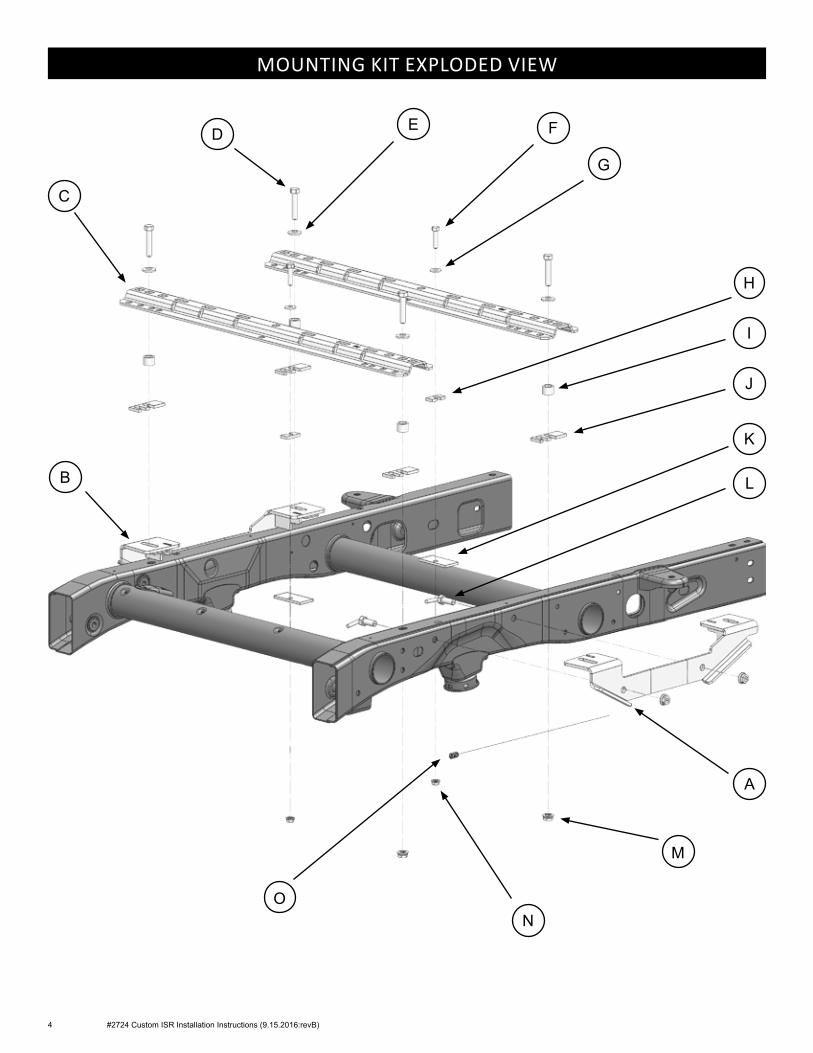
MOUNTING KIT EXPLODED VIEW
A
C
M
O
D
H
E
K
J
I
F
G
N
#2724 Custom ISR Installation Instructions (9.15.2016:revB) 5
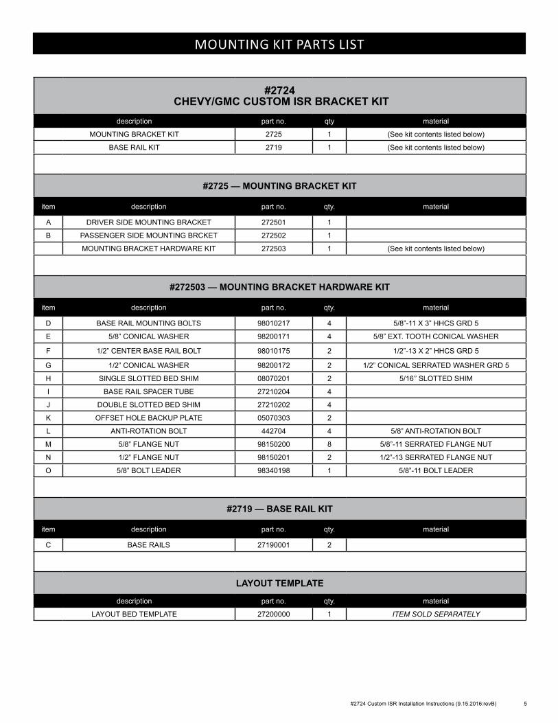
#2724 CHEVY/GMC CUSTOM ISR BRACKET KIT
description part no. qty material
MOUNTING BRACKET KIT 2725 1 (See kit contents listed below)
BASE RAIL KIT 2719 1 (See kit contents listed below)
#2725 — MOUNTING BRACKET KIT
item description part no. qty. material
A DRIVER SIDE MOUNTING BRACKET 272501 1
B PASSENGER SIDE MOUNTING BRCKET 272502 1
MOUNTING BRACKET HARDWARE KIT 272503 1 (See kit contents listed below)
#272503 — MOUNTING BRACKET HARDWARE KIT
item description part no. qty. material
D BASE RAIL MOUNTING BOLTS 98010217 4 5/8”-11 X 3” HHCS GRD 5
E 5/8” CONICAL WASHER 98200171 4 5/8” EXT. TOOTH CONICAL WASHER
F 1/2” CENTER BASE RAIL BOLT 98010175 2 1/2”-13 X 2” HHCS GRD 5
G 1/2” CONICAL WASHER 98200172 2 1/2” CONICAL SERRATED WASHER GRD 5
H SINGLE SLOTTED BED SHIM 08070201 2 5/16’’ SLOTTED SHIM
I BASE RAIL SPACER TUBE 27210204 4
J DOUBLE SLOTTED BED SHIM 27210202 4
K OFFSET HOLE BACKUP PLATE 05070303 2
L ANTI-ROTATION BOLT 442704 4 5/8” ANTI-ROTATION BOLT
M 5/8” FLANGE NUT 98150200 8 5/8”-11 SERRATED FLANGE NUT
N 1/2” FLANGE NUT 98150201 2 1/2”-13 SERRATED FLANGE NUT
O 5/8” BOLT LEADER 98340198 1 5/8”-11 BOLT LEADER
#2719 — BASE RAIL KIT
item description part no. qty. material
C BASE RAILS 27190001 2
LAYOUT TEMPLATE
description part no. qty. material
LAYOUT BED TEMPLATE 27200000 1 ITEM SOLD SEPARATELY
MOUNTING KIT PARTS LIST
6 #2724 Custom ISR Installation Instructions (9.15.2016:revB)
TRUCK PREPARATION
1. Block vehicle wheels. Some vehicles may require you to raise the rear of the truck to install the mounting brackets on the truck frame.
2. You may wish to remove the wheels to give yourself greater working room.
MARKING THE TRUCK BED FOR DRILLING
LAYOUT METHOD
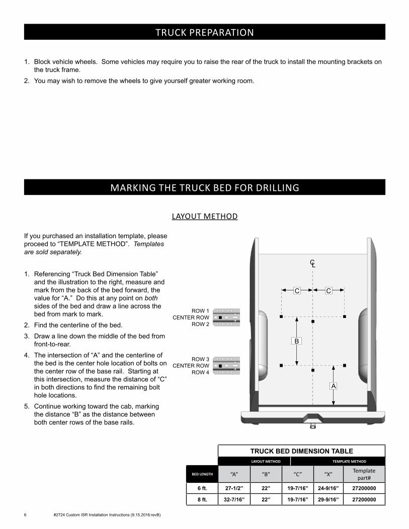
If you purchased an installation template, please proceed to “TEMPLATE METHOD”. Templates are sold separately.
1. Referencing “Truck Bed Dimension Table” and the illustration to the right, measure and mark from the back of the bed forward, the value for “A.” Do this at any point on both sides of the bed and draw a line across the bed from mark to mark.
2. Find the centerline of the bed.3. Draw a line down the middle of the bed from
front-to-rear.4. The intersection of “A” and the centerline of
the bed is the center hole location of bolts on the center row of the base rail. Starting at this intersection, measure the distance of “C” in both directions to find the remaining bolt hole locations.
5. Continue working toward the cab, marking the distance “B” as the distance between both center rows of the base rails.
CL
C
B
A
TRUCK BED DIMENSION TABLELAYOUT METHOD TEMPLATE METHOD
BED LENGTH “A” “B” “C” “X” Template part#
6 ft. 27-1/2” 22” 19-7/16” 24-9/16” 27200000
8 ft. 32-7/16” 22” 19-7/16” 29-9/16” 27200000
ROW 2
C
CENTER ROWROW 1
ROW 4CENTER ROW
ROW 3
#2724 Custom ISR Installation Instructions (9.15.2016:revB) 7
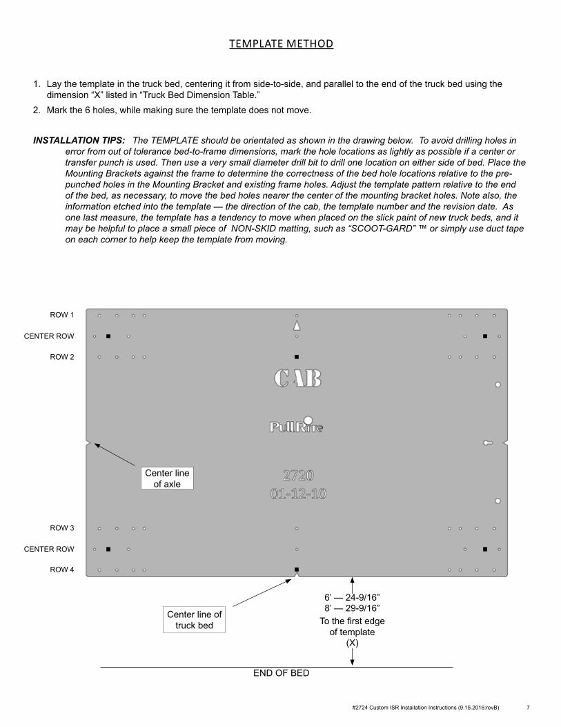
1. Lay the template in the truck bed, centering it from side-to-side, and parallel to the end of the truck bed using the dimension “X” listed in “Truck Bed Dimension Table.”
2. Mark the 6 holes, while making sure the template does not move.
INSTALLATION TIPS: The TEMPLATE should be orientated as shown in the drawing below. To avoid drilling holes in error from out of tolerance bed-to-frame dimensions, mark the hole locations as lightly as possible if a center or transfer punch is used. Then use a very small diameter drill bit to drill one location on either side of bed. Place the Mounting Brackets against the frame to determine the correctness of the bed hole locations relative to the pre-punched holes in the Mounting Bracket and existing frame holes. Adjust the template pattern relative to the end of the bed, as necessary, to move the bed holes nearer the center of the mounting bracket holes. Note also, the information etched into the template — the direction of the cab, the template number and the revision date. As one last measure, the template has a tendency to move when placed on the slick paint of new truck beds, and it may be helpful to place a small piece of NON-SKID matting, such as “SCOOT-GARD” ™ or simply use duct tape on each corner to help keep the template from moving.
TEMPLATE METHOD
ROW 1
ROW 2
ROW 3
ROW 4
END OF BED
Center line of truck bed
Center line of axle
8’ — 29-9/16”To the first edge
of template(X)
6’ — 24-9/16”
CENTER ROW
CENTER ROW
8 #2724 Custom ISR Installation Instructions (9.15.2016:revB)
INSTALLATION
Since most truck beds are not installed square to the frame or are the same distance from the back of the cab, the installer will need to make sure the bed holes line up properly with the center of each mounting bolt hole.
The basic steps in this section are as follows:• Layout the bed holes• Drill the first pilot hole in the bed• Check centering• Adjust the bed hole layout if necessary• Drill the second pilot hole and check centering to ensure bed hole locations are square to the frame; adjust as
needed• Drill remaining pilot holes in the bed; check centering
Detailed Installation Instructions
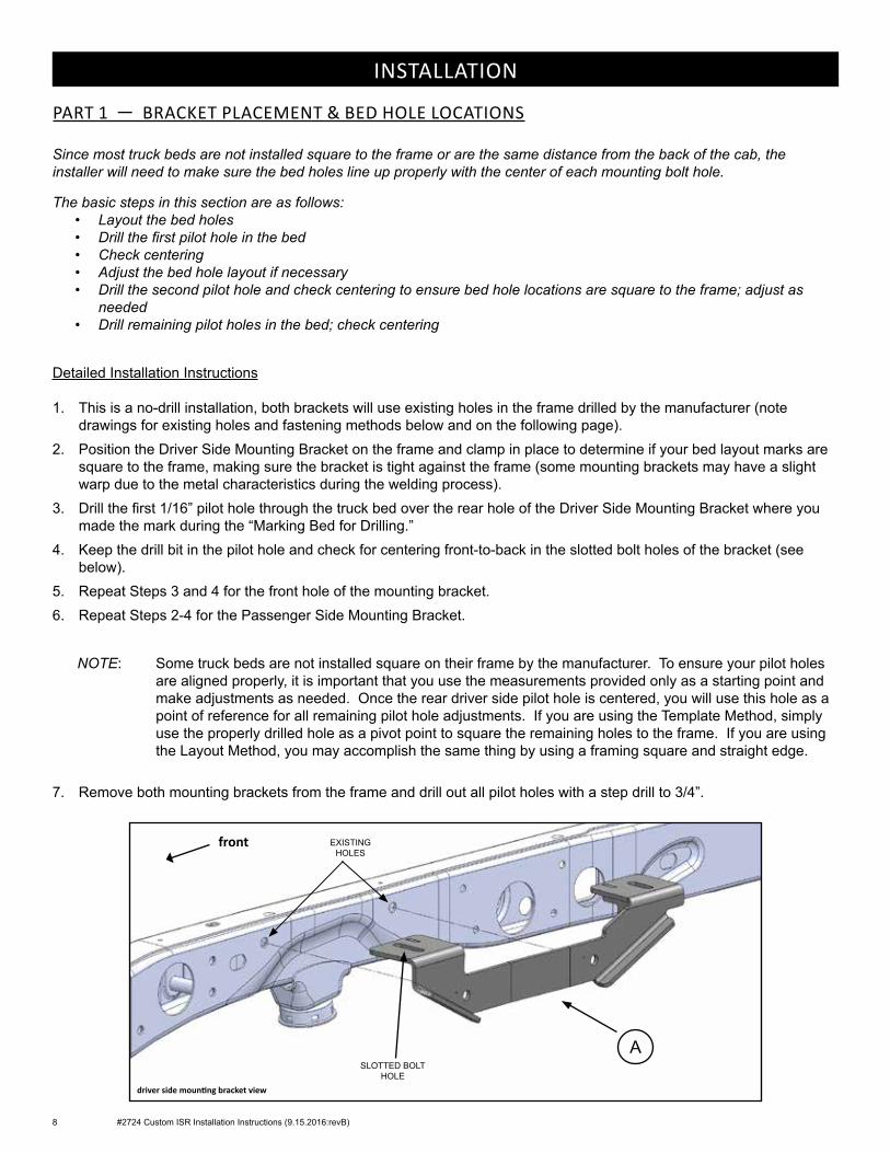
1. This is a no-drill installation, both brackets will use existing holes in the frame drilled by the manufacturer (note drawings for existing holes and fastening methods below and on the following page).
2. Position the Driver Side Mounting Bracket on the frame and clamp in place to determine if your bed layout marks are square to the frame, making sure the bracket is tight against the frame (some mounting brackets may have a slight warp due to the metal characteristics during the welding process).
3. Drill the first 1/16” pilot hole through the truck bed over the rear hole of the Driver Side Mounting Bracket where you made the mark during the “Marking Bed for Drilling.”
4. Keep the drill bit in the pilot hole and check for centering front-to-back in the slotted bolt holes of the bracket (see below).
5. Repeat Steps 3 and 4 for the front hole of the mounting bracket.6. Repeat Steps 2-4 for the Passenger Side Mounting Bracket.
NOTE: Some truck beds are not installed square on their frame by the manufacturer. To ensure your pilot holes are aligned properly, it is important that you use the measurements provided only as a starting point and make adjustments as needed. Once the rear driver side pilot hole is centered, you will use this hole as a point of reference for all remaining pilot hole adjustments. If you are using the Template Method, simply use the properly drilled hole as a pivot point to square the remaining holes to the frame. If you are using the Layout Method, you may accomplish the same thing by using a framing square and straight edge.
7. Remove both mounting brackets from the frame and drill out all pilot holes with a step drill to 3/4”.
PART 1 — BRACKET PLACEMENT & BED HOLE LOCATIONS
driver side mounting bracket view
EXISTING HOLES
A
front
SLOTTED BOLT HOLE
#2724 Custom ISR Installation Instructions (9.15.2016:revB) 9
INSTALLATION
PART 2 — BRACKET INSTALLATION
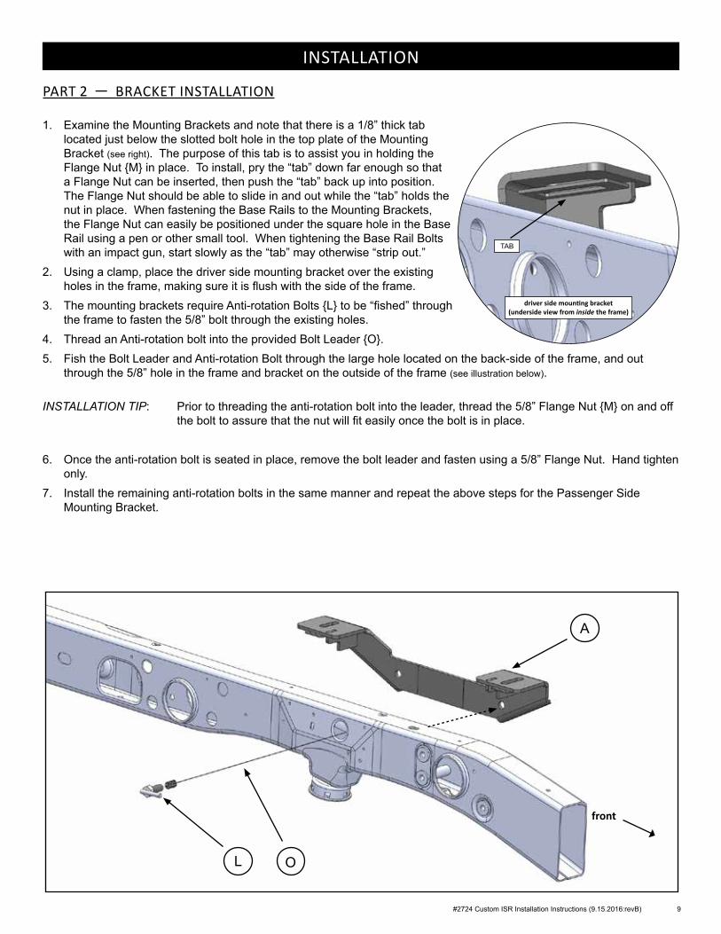
1. Examine the Mounting Brackets and note that there is a 1/8” thick tab located just below the slotted bolt hole in the top plate of the Mounting Bracket (see right). The purpose of this tab is to assist you in holding the Flange Nut {M} in place. To install, pry the “tab” down far enough so that a Flange Nut can be inserted, then push the “tab” back up into position. The Flange Nut should be able to slide in and out while the “tab” holds the nut in place. When fastening the Base Rails to the Mounting Brackets, the Flange Nut can easily be positioned under the square hole in the Base Rail using a pen or other small tool. When tightening the Base Rail Bolts with an impact gun, start slowly as the “tab” may otherwise “strip out.”
2. Using a clamp, place the driver side mounting bracket over the existing holes in the frame, making sure it is flush with the side of the frame.
3. The mounting brackets require Anti-rotation Bolts {L} to be “fished” through the frame to fasten the 5/8” bolt through the existing holes.
4. Thread an Anti-rotation bolt into the provided Bolt Leader {O}.5. Fish the Bolt Leader and Anti-rotation Bolt through the large hole located on the back-side of the frame, and out
through the 5/8” hole in the frame and bracket on the outside of the frame (see illustration below).
INSTALLATION TIP: Prior to threading the anti-rotation bolt into the leader, thread the 5/8” Flange Nut {M} on and off the bolt to assure that the nut will fit easily once the bolt is in place.
6. Once the anti-rotation bolt is seated in place, remove the bolt leader and fasten using a 5/8” Flange Nut. Hand tighten only.
7. Install the remaining anti-rotation bolts in the same manner and repeat the above steps for the Passenger Side Mounting Bracket.
A
L O
front
TAB
driver side mounting bracket (underside view from inside the frame)
10 #2724 Custom ISR Installation Instructions (9.15.2016:revB)
INSTALLATION
TORQUE TABLE3/8” bolt — 31 ft. lbs.1/2” bolt — 75 ft. lbs.5/8” bolt — 151 ft. lbs.3/4” bolt — 266 ft. lbs.
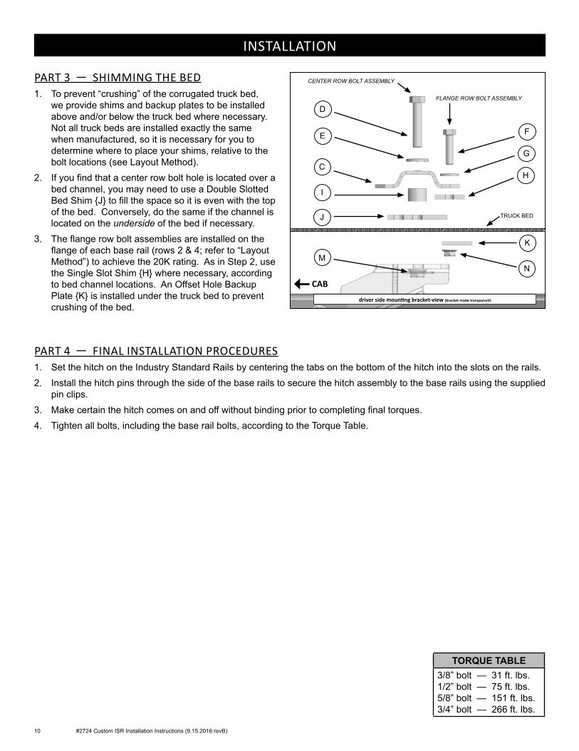
PART 3 — SHIMMING THE BED1. To prevent “crushing” of the corrugated truck bed,
we provide shims and backup plates to be installed above and/or below the truck bed where necessary. Not all truck beds are installed exactly the same when manufactured, so it is necessary for you to determine where to place your shims, relative to the bolt locations (see Layout Method).
2. If you find that a center row bolt hole is located over a bed channel, you may need to use a Double Slotted Bed Shim {J} to fill the space so it is even with the top of the bed. Conversely, do the same if the channel is located on the underside of the bed if necessary.
3. The flange row bolt assemblies are installed on the flange of each base rail (rows 2 & 4; refer to “Layout Method”) to achieve the 20K rating. As in Step 2, use the Single Slot Shim {H} where necessary, according to bed channel locations. An Offset Hole Backup Plate {K} is installed under the truck bed to prevent crushing of the bed.
PART 4 — FINAL INSTALLATION PROCEDURES1. Set the hitch on the Industry Standard Rails by centering the tabs on the bottom of the hitch into the slots on the rails.2. Install the hitch pins through the side of the base rails to secure the hitch assembly to the base rails using the supplied
pin clips.3. Make certain the hitch comes on and off without binding prior to completing final torques.4. Tighten all bolts, including the base rail bolts, according to the Torque Table.
driver side mounting bracket‑view (bracket made transparent)
D
E
C
I
F
TRUCK BED
K
CENTER ROW BOLT ASSEMBLY
FLANGE ROW BOLT ASSEMBLY
G
NM
H
J
CAB

#2724 Custom ISR Installation Instructions (9.15.2016:revB) 11

MANUFACTURED BY:PULLIAM ENTERPRISES, INC.
13790 East Jefferson Blvd.Mishawaka, IN 46545
(574) 259-1520 • (800) [email protected] • www.pullrite.com