Embed Size (px)
Citation preview
Additives & InstrumentsA member of
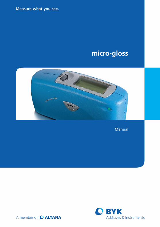
Measure what you see.
micro-gloss
Manual
Engl
ish
micro-gloss
Manual
Patent pending 260 020 398 E 0812
BYK-Gardner GmbHLausitzer Str. 8D-82538 GeretsriedGermanyTel. 0-800-gardner
(0-800-4273637)+49-8171-3493-0
Fax +49-8171-3493-140
BYK - Gardner USA9104 Guilford RoadColumbia, MD 21046USAPhone 800-343-7721
301-483-6500Fax 800-394-8215
301-483-6555
www.byk.com/instruments

2
Dear customer,thank you for having decided for a BYK-Gardnerproduct. BYK-Gardner is committed to providing youwith quality products and services. We offercomplete system solutions to solve your problemsin areas of gloss and physical properties. As thebasis of our worldwide business, we strongly believein total customer satisfaction. Therefore, in additionto our products, we offer many VALUE-ADDEDservices:· Technical Sales Force· Technical & Application Support· Application and Technical Seminars· Repair & Certification Service
BYK-Gardner is part of Altana AG and a directsubsidiary of BYK-Chemie GmbH, a leading supplierof additives for coatings and plastics. Together, weoffer complete and unique solutions for you, ourcustomer.
Thank you for your trust and confidence. If there isanything we can do better to serve your needs, donot hesitate to let us know.
Your BYK-Gardner Team
3
Engl
ishTable of content
1. Safety instructions ................................................................................ 7
2. System description and Delivery notes ............................................ 12
3. Power supply ...................................................................................... 153.1 Power supply battery/accumulator operated ...................................... 153.2 Changing the battery/accumulator ....................................................... 163.3 External power supply ........................................................................... 16
4. Controls ............................................................................................... 17
5. Getting started .................................................................................... 195.1 Turning on and measuring ..................................................................... 195.2 Navigation ............................................................................................... 205.3 Change names/numbers ....................................................................... 215.4 Overview of main menu ......................................................................... 22
6. Calibrate .............................................................................................. 236.1 Autodiagnosis ......................................................................................... 236.2 Calibrate .................................................................................................. 24
6.2.1 Gloss ............................................................................................ 246.2.2 Thickness ..................................................................................... 246.2.3 Change cal. values ...................................................................... 256.2.4 State .............................................................................................. 266.2.5 Scale gloss .................................................................................. 276.2.6 Scale thickness ............................................................................ 27
6.3 Calibrating standards ............................................................................ 286.4 Checking standard ................................................................................. 28
7. Measurement techniques .................................................................. 297.1 Paints and varnishes, plastics and similar material ........................... 297.2 Anodized aluminum and other metal surfaces .................................... 307.3 Measurement of film thickness ............................................................ 31
8. Measurement Modes .......................................................................... 328.1 Sample mode .......................................................................................... 32
Table of content
4
8.2 Statistics ................................................................................................. 338.2.1 Number of measurements .......................................................... 348.2.2 Display ......................................................................................... 358.2.3 Exit block ...................................................................................... 368.2.4 Delete block ................................................................................. 368.2.5 Delete measurement ................................................................... 36
8.3 Continuous .............................................................................................. 378.4 Basic mode ............................................................................................. 38
9. Geometry/sensor ................................................................................ 399.1 Geometry selection ................................................................................ 399.2 Thickness sensor selection .................................................................. 399.3 Sensor setting combi ............................................................................. 40
10. Memory ............................................................................................... 4110.1 Memory ................................................................................................... 4110.2 Select memory ....................................................................................... 4110.3 Create memory ....................................................................................... 4210.4 Delete memory ....................................................................................... 4210.5 Display memory ...................................................................................... 42
11. Difference measurement and Pass/Fail ........................................... 4411.1 Difference ............................................................................................... 4411.2 Measure standard .................................................................................. 4411.3 Select standard ...................................................................................... 4511.4 Create standard ..................................................................................... 4611.5 Change standard .................................................................................... 4711.6 Delete standard ...................................................................................... 47
12. Setup ................................................................................................... 4812.1 Bluetooth® .............................................................................................. 4812.2 Date/time ................................................................................................. 4812.3 Beeper ..................................................................................................... 4812.4 Display time ............................................................................................ 4812.5 Language ................................................................................................ 4912.6 Info ........................................................................................................... 49
Table of content
5
13. Interface .............................................................................................. 5013.1 Installation .............................................................................................. 51
14. Standards ............................................................................................ 52
15. Technical Data .................................................................................... 54
16. Errors and Warning Messages ........................................................... 56
17. Cleaning and Maintenance ............................................................... 58
18. Service and Certification .................................................................. 59
19. Copyright ............................................................................................. 61
Table of content

6
7
1. Safety instructions • Before operating the instrument the first time,
please read the operating instructions and takeparticular notice of the safety instructions.
• If you use the unit and accessories properly,there are no hazards to fear.
• This product is equipped with safety features.Nevertheless, read the safety warnings carefullyand use the product only as described in theseinstructions to avoid accidental injury or damage.
• No claims of product liability or warranty can behonored if the device is not operated inaccordance with the operating instructions.
• Keep these instructions for future reference.
• If you pass this instrument to somebody else,make sure to include these instructions.
Safety instructions
8
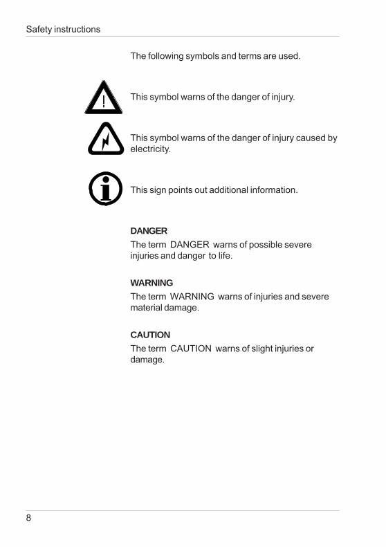
The following symbols and terms are used.
This symbol warns of the danger of injury.
This symbol warns of the danger of injury caused byelectricity.
This sign points out additional information.
DANGERThe term DANGER warns of possible severeinjuries and danger to life.
WARNINGThe term WARNING warns of injuries and severematerial damage.
CAUTIONThe term CAUTION warns of slight injuries ordamage.
Safety instructions
9
Safety instructions
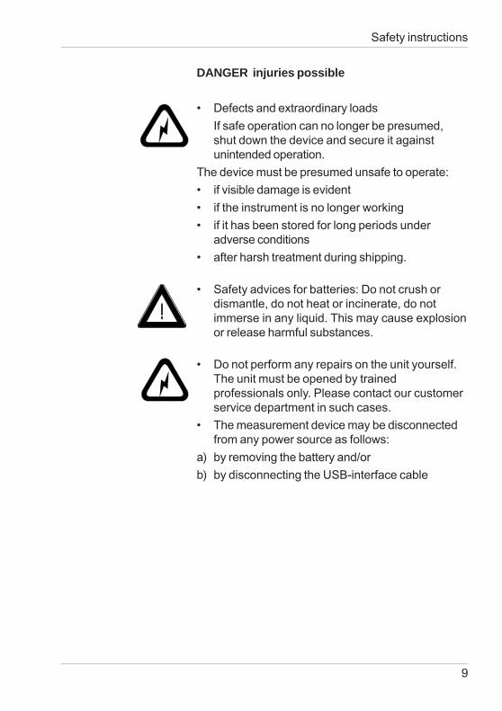
DANGER injuries possible
• Defects and extraordinary loadsIf safe operation can no longer be presumed,shut down the device and secure it againstunintended operation.
The device must be presumed unsafe to operate:• if visible damage is evident• if the instrument is no longer working• if it has been stored for long periods under
adverse conditions• after harsh treatment during shipping.
• Safety advices for batteries: Do not crush ordismantle, do not heat or incinerate, do notimmerse in any liquid. This may cause explosionor release harmful substances.
• Do not perform any repairs on the unit yourself.The unit must be opened by trainedprofessionals only. Please contact our customerservice department in such cases.
• The measurement device may be disconnectedfrom any power source as follows:
a) by removing the battery and/orb) by disconnecting the USB-interface cable
10
Safety instructions
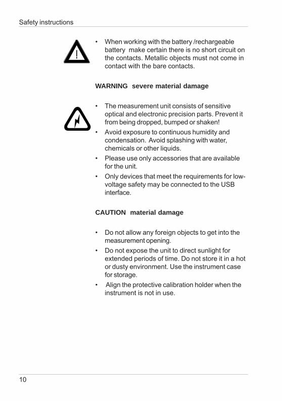
• When working with the battery /rechargeablebattery make certain there is no short circuit onthe contacts. Metallic objects must not come incontact with the bare contacts.
WARNING severe material damage
• The measurement unit consists of sensitiveoptical and electronic precision parts. Prevent itfrom being dropped, bumped or shaken!
• Avoid exposure to continuous humidity andcondensation. Avoid splashing with water,chemicals or other liquids.
• Please use only accessories that are availablefor the unit.
• Only devices that meet the requirements for low-voltage safety may be connected to the USBinterface.
CAUTION material damage
• Do not allow any foreign objects to get into themeasurement opening.
• Do not expose the unit to direct sunlight forextended periods of time. Do not store it in a hotor dusty environment. Use the instrument casefor storage.
• Align the protective calibration holder when theinstrument is not in use.
11
• Avoid prolonged high relative humidity and donot allow condensation water.
• Do not use any acetone for cleaning theunit! The unit housing is resistant to manysolvents. For cleaning you should use a soft,moist cloth. Excessive dirt and dust can beremoved with ethanol or cleaning alcohol.
• In case you intend not to use the instrument fora longer period of time, take out the battery.
Additonal information on use:
• You will find the technical data for all systemcomponents on the respective manufacturer’splates and in the section Technical Data
• Batteries and rechargeable batteries are specialwaste and must therefore not be disposed of withhousehold trash. Make certain to observe thedisposal instructions of the battery orrechargeable battery manufacturer.
Safety instructions
12
System description and Delivery notes
2. System description and Delivery notesMeasurement units of the micro-gloss family can beused to determine the gloss level of paint coatings,plastics, ceramics and metal surfaces. The micro-TRI-gloss μ additionally allows to measure the filmthickness of paint and coatings on magnetic (Fe)and non-magnetic base metals (NFe).Light is directed at the surface of the sample at adefined angle and the reflected light is measuredphotoelectrically (reflectometer).
Depending on the typical gloss level of the testobject, reflectometers that direct light onto thesurface at different angles (geometry) can be used.Measurement units are equipped with standardgeometries of 20°, 60° or 85°. All three of thesegeometries are integrated into the micro-TRI-gloss.Functions described in this manual in terms ofgeometry selection are only available with the threeangle device.
In addition to measuring individual gloss values, it isalso possible to record, save and statisticallyevaluate series of measurements consisting of up to999 values.
The operate button and scroll wheel are used tocontrol the system. System operation is supportedby display messages (autodiagnosis and errormessages).
The measurement unit conforms to the standardsDIN 67530, ISO 2813, ASTM D 523 and BS 3900Part D 5.
13
Instrument type:
micro-gloss 20° 4440micro-gloss 60° 4442micro-gloss 85° 4444
micro-TRI-gloss 4446micro-TRI-gloss μ 4448
micro-gloss 60° S 4450micro-TRI-gloss S 4452
Comes complete with:Measurement device, Protective holder withintegrated calibration tile, Traceable certificate,Software easy-link and USB driver on CD, USB-cable, Bluetooth® adapter with driver on CD,Operating manual on CD, Quick user guide andSafety instructions, Battery, Carrying case.
micro-TRI-gloss μ delivery includes additionallyFe and NFe zero standards.
System description and Delivery notes
14
Recommended accessories:Checking standards for control of test equipment
for micro-gloss 20° 4422for micro-gloss 60° 4462for micro-gloss 85° 4487
for micro-TRI-gloss 4434and micro-TRI-gloss μ
micro-gloss 60° S 4464micro-TRI-gloss S 4438
mirror type, highly reflective 4433for 20°, 60° and 85°
System description and Delivery notes
15
Power supply
3. Power supplyBefore operating the instrument for the first time,please read the operating instructions and payattention to the safety instructions in Chapter 1.Unpack the device and check to make certain allpieces have been included with delivery (for scope ofdelivery, see Section Delivery notes).
3.1 Power supply battery-operated
The battery must be placed in the measuring unit foroperation service. The device runs on one AA 1.5-Valkaline or 1.2-V NiMH rechargeable battery.Use only alkaline batteries or NiMHrechargeables (AA /LR6)!Depending on the exact brand, the capacity of eachbattery is sufficient for about 10,000 measurements.When the battery voltage falls below the requiredminimum voltage in the course of operation, thefollowing message appears on the display
Battery low!To ensure that the unit is always ready for operation,it is recommended to have a spare battery handy,especially when performing measurements in thefield.
16
Power supply
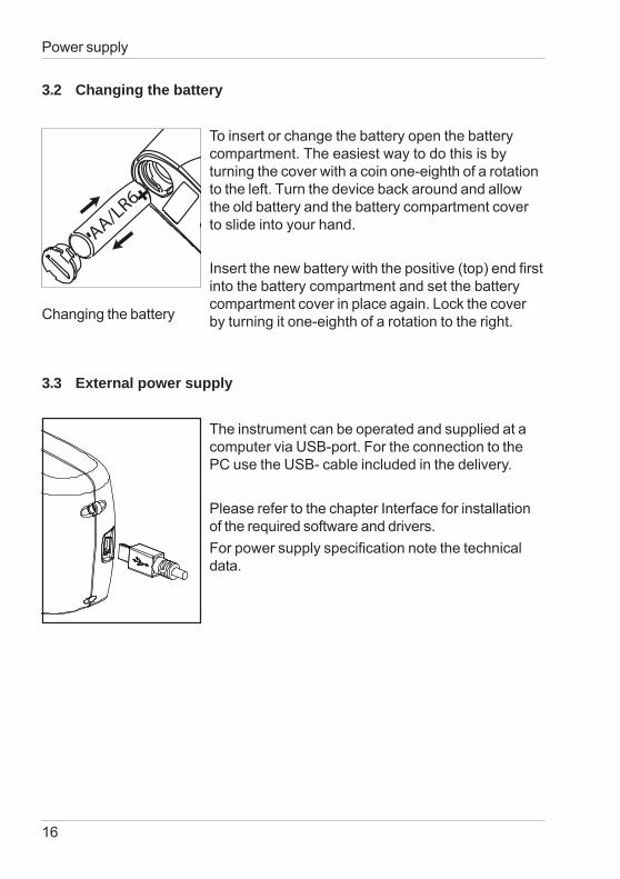
3.2 Changing the battery
To insert or change the battery open the batterycompartment. The easiest way to do this is byturning the cover with a coin one-eighth of a rotationto the left. Turn the device back around and allowthe old battery and the battery compartment coverto slide into your hand.
Insert the new battery with the positive (top) end firstinto the battery compartment and set the batterycompartment cover in place again. Lock the coverby turning it one-eighth of a rotation to the right.
3.3 External power supply
The instrument can be operated and supplied at acomputer via USB-port. For the connection to thePC use the USB- cable included in the delivery.
Please refer to the chapter Interface for installationof the required software and drivers.For power supply specification note the technicaldata.
Changing the battery
+
- AA/LR6
17
Controls
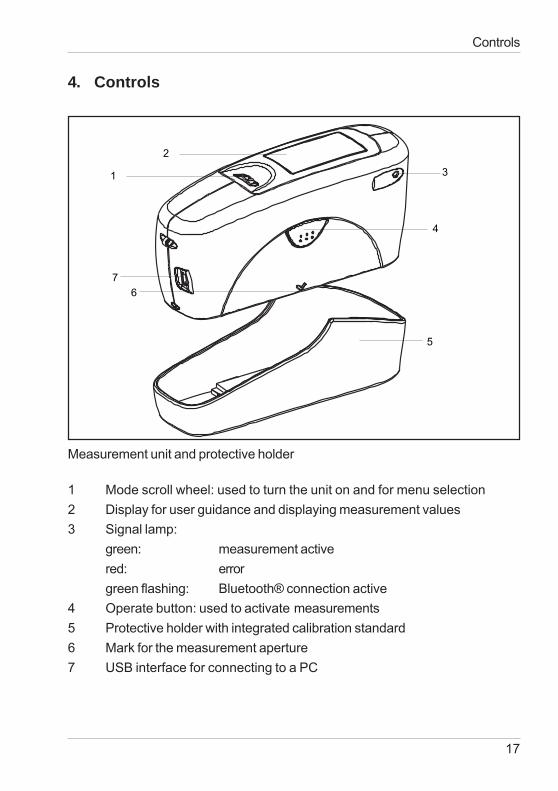
Measurement unit and protective holder
1 Mode scroll wheel: used to turn the unit on and for menu selection2 Display for user guidance and displaying measurement values3 Signal lamp:
green: measurement activered: errorgreen flashing: Bluetooth® connection active
4 Operate button: used to activate measurements5 Protective holder with integrated calibration standard6 Mark for the measurement aperture7 USB interface for connecting to a PC
1
2
4
3
67
5
4. Controls
18
Controls
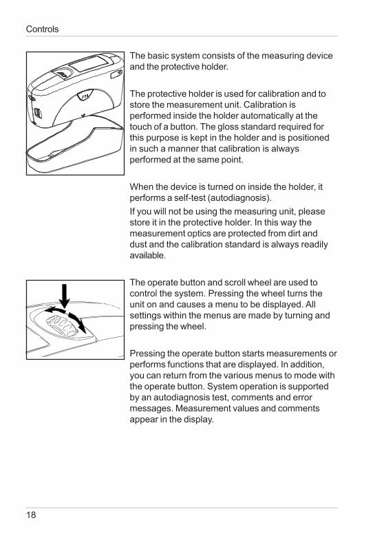
The basic system consists of the measuring deviceand the protective holder.
The protective holder is used for calibration and tostore the measurement unit. Calibration isperformed inside the holder automatically at thetouch of a button. The gloss standard required forthis purpose is kept in the holder and is positionedin such a manner that calibration is alwaysperformed at the same point.
When the device is turned on inside the holder, itperforms a self-test (autodiagnosis).If you will not be using the measuring unit, pleasestore it in the protective holder. In this way themeasurement optics are protected from dirt anddust and the calibration standard is always readilyavailable.
The operate button and scroll wheel are used tocontrol the system. Pressing the wheel turns theunit on and causes a menu to be displayed. Allsettings within the menus are made by turning andpressing the wheel.
Pressing the operate button starts measurements orperforms functions that are displayed. In addition,you can return from the various menus to mode withthe operate button. System operation is supportedby an autodiagnosis test, comments and errormessages. Measurement values and commentsappear in the display.
19
Getting started
5. Getting started
5.1 Turning on the unit and measuring
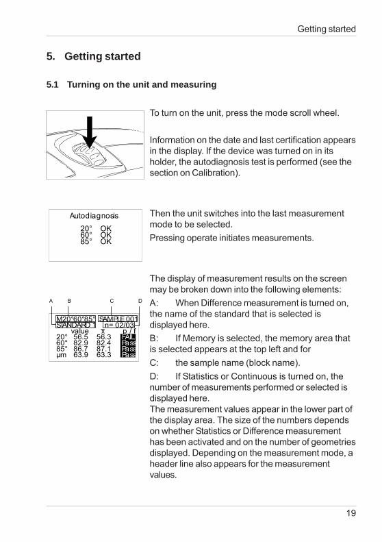
To turn on the unit, press the mode scroll wheel.
Information on the date and last certification appearsin the display. If the device was turned on in itsholder, the autodiagnosis test is performed (see thesection on Calibration).
Then the unit switches into the last measurementmode to be selected.Pressing operate initiates measurements.
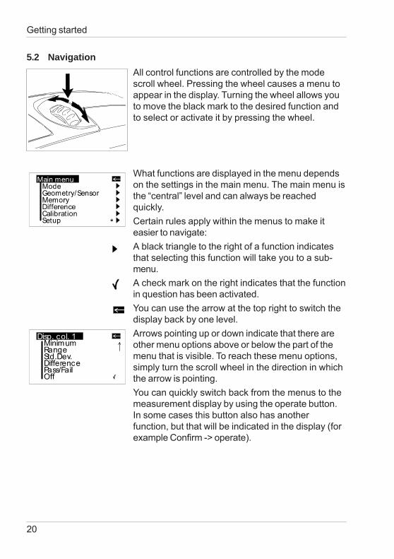
The display of measurement results on the screenmay be broken down into the following elements:A: When Difference measurement is turned on,the name of the standard that is selected isdisplayed here.B: If Memory is selected, the memory area thatis selected appears at the top left and forC: the sample name (block name).D: If Statistics or Continuous is turned on, thenumber of measurements performed or selected isdisplayed here.The measurement values appear in the lower part ofthe display area. The size of the numbers dependson whether Statistics or Difference measurementhas been activated and on the number of geometriesdisplayed. Depending on the measurement mode, aheader line also appears for the measurementvalues.
20
Getting started
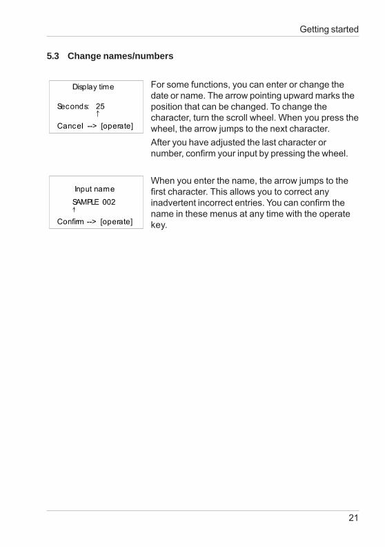
5.2 NavigationAll control functions are controlled by the modescroll wheel. Pressing the wheel causes a menu toappear in the display. Turning the wheel allows youto move the black mark to the desired function andto select or activate it by pressing the wheel.
What functions are displayed in the menu dependson the settings in the main menu. The main menu isthe “central” level and can always be reachedquickly.Certain rules apply within the menus to make iteasier to navigate:A black triangle to the right of a function indicatesthat selecting this function will take you to a sub-menu.A check mark on the right indicates that the functionin question has been activated.You can use the arrow at the top right to switch thedisplay back by one level.Arrows pointing up or down indicate that there areother menu options above or below the part of themenu that is visible. To reach these menu options,simply turn the scroll wheel in the direction in whichthe arrow is pointing.You can quickly switch back from the menus to themeasurement display by using the operate button.In some cases this button also has anotherfunction, but that will be indicated in the display (forexample Confirm -> operate).
21
Getting started
5.3 Change names/numbers
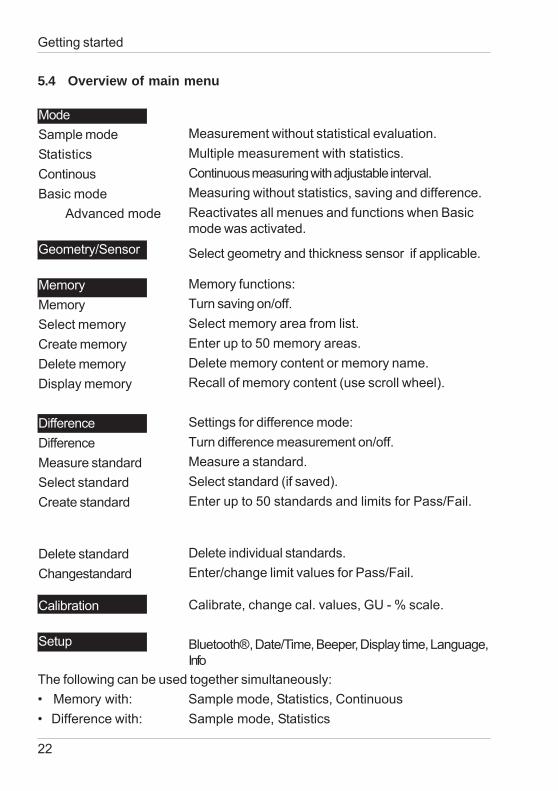
For some functions, you can enter or change thedate or name. The arrow pointing upward marks theposition that can be changed. To change thecharacter, turn the scroll wheel. When you press thewheel, the arrow jumps to the next character.After you have adjusted the last character ornumber, confirm your input by pressing the wheel.
When you enter the name, the arrow jumps to thefirst character. This allows you to correct anyinadvertent incorrect entries. You can confirm thename in these menus at any time with the operatekey.
22
Getting started
Measurement without statistical evaluation.Multiple measurement with statistics.Continuous measuring with adjustable interval.Measuring without statistics, saving and difference.Reactivates all menues and functions when Basicmode was activated.
Memory functions:Turn saving on/off.Select memory area from list.Enter up to 50 memory areas.Delete memory content or memory name.Recall of memory content (use scroll wheel).
Settings for difference mode:Turn difference measurement on/off.Measure a standard.Select standard (if saved).Enter up to 50 standards and limits for Pass/Fail.
Delete individual standards.Enter/change limit values for Pass/Fail.
The following can be used together simultaneously:
ModeSample modeStatisticsContinousBasic mode Advanced mode
Geometry/Sensor
MemoryMemorySelect memoryCreate memoryDelete memoryDisplay memory
DifferenceDifferenceMeasure standardSelect standardCreate standard
Delete standardChangestandard
Calibration
Setup
Calibrate, change cal. values, GU - % scale.
Bluetooth®, Date/Time, Beeper, Display time, Language,Info
5.4 Overview of main menu
Select geometry and thickness sensor if applicable.
• Memory with: Sample mode, Statistics, Continuous• Difference with: Sample mode, Statistics
23
Calibrate
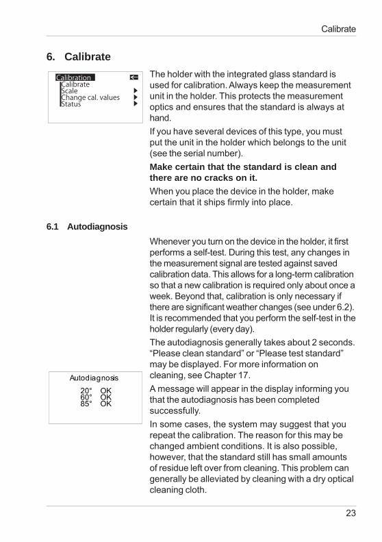
6. CalibrateThe holder with the integrated glass standard isused for calibration. Always keep the measurementunit in the holder. This protects the measurementoptics and ensures that the standard is always athand.If you have several devices of this type, you mustput the unit in the holder which belongs to the unit(see the serial number).Make certain that the standard is clean andthere are no cracks on it.When you place the device in the holder, makecertain that it ships firmly into place.
6.1 AutodiagnosisWhenever you turn on the device in the holder, it firstperforms a self-test. During this test, any changes inthe measurement signal are tested against savedcalibration data. This allows for a long-term calibrationso that a new calibration is required only about once aweek. Beyond that, calibration is only necessary ifthere are significant weather changes (see under 6.2).It is recommended that you perform the self-test in theholder regularly (every day).The autodiagnosis generally takes about 2 seconds.“Please clean standard” or “Please test standard”may be displayed. For more information oncleaning, see Chapter 17.A message will appear in the display informing youthat the autodiagnosis has been completedsuccessfully.In some cases, the system may suggest that yourepeat the calibration. The reason for this may bechanged ambient conditions. It is also possible,however, that the standard still has small amountsof residue left over from cleaning. This problem cangenerally be alleviated by cleaning with a dry opticalcleaning cloth.
CalibrationCalibrateScaleChange cal. valuesStatus
24
Calibrate
6.2 CalibrateYou should recalibrate the device if ambientconditions have changed. This applies especiallywhen changing location if major changes intemperature and relative humidity may be expectedas a result (for example inside/outside).When moving from cold areas to warm areas, thereis a danger of condensation. For this reason, afterthere has been a change in ambient conditions, youshould wait for an appropriate amount of time toallow the optical components to adjust beforecalibrating and using the unit.
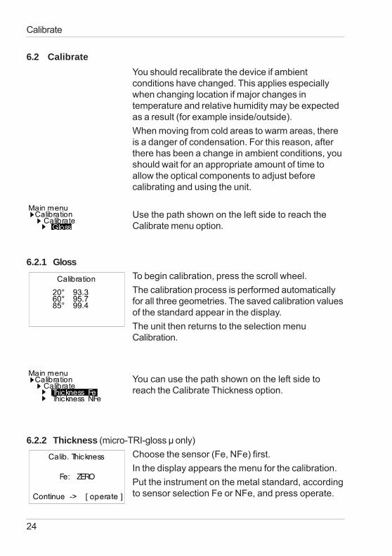
Use the path shown on the left side to reach theCalibrate menu option.
6.2.1 GlossTo begin calibration, press the scroll wheel.The calibration process is performed automaticallyfor all three geometries. The saved calibration valuesof the standard appear in the display.The unit then returns to the selection menuCalibration.
You can use the path shown on the left side toreach the Calibrate Thickness option.
6.2.2 Thickness (micro-TRI-gloss μ only)Choose the sensor (Fe, NFe) first.In the display appears the menu for the calibration.Put the instrument on the metal standard, accordingto sensor selection Fe or NFe, and press operate.
25
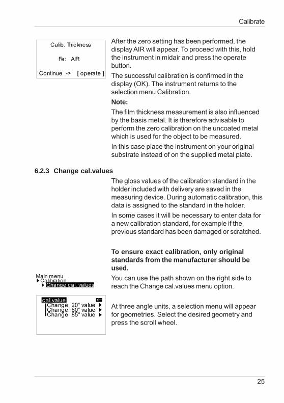
After the zero setting has been performed, thedisplay AIR will appear. To proceed with this, holdthe instrument in midair and press the operatebutton.The successful calibration is confirmed in thedisplay (OK). The instrument returns to theselection menu Calibration.Note:The film thickness measurement is also influencedby the basis metal. It is therefore advisable toperform the zero calibration on the uncoated metalwhich is used for the object to be measured.In this case place the instrument on your originalsubstrate instead of on the supplied metal plate.
6.2.3 Change cal.valuesThe gloss values of the calibration standard in theholder included with delivery are saved in themeasuring device. During automatic calibration, thisdata is assigned to the standard in the holder.In some cases it will be necessary to enter data fora new calibration standard, for example if theprevious standard has been damaged or scratched.
To ensure exact calibration, only originalstandards from the manufacturer should beused.You can use the path shown on the right side toreach the Change cal.values menu option.
At three angle units, a selection menu will appearfor geometries. Select the desired geometry andpress the scroll wheel.
Calibrate
26
Calibrate
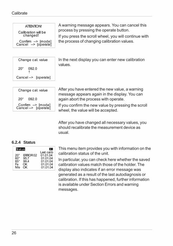
A warning message appears. You can cancel thisprocess by pressing the operate button.If you press the scroll wheel, you will continue withthe process of changing calibration values.
In the next display you can enter new calibrationvalues.
After you have entered the new value, a warningmessage appears again in the display. You canagain abort the process with operate.If you confirm the new value by pressing the scrollwheel, the value will be accepted.
After you have changed all necessary values, youshould recalibrate the measurement device asusual.
6.2.4 StatusThis menu item provides you with information on thecalibration status of the unit.In particular, you can check here whether the savedcalibration values match those of the holder. Thedisplay also indicates if an error message wasgenerated as a result of the last autodiagnosis orcalibration. If this has happened, further informationis available under Section Errors and warningmessages.
27
Calibrate
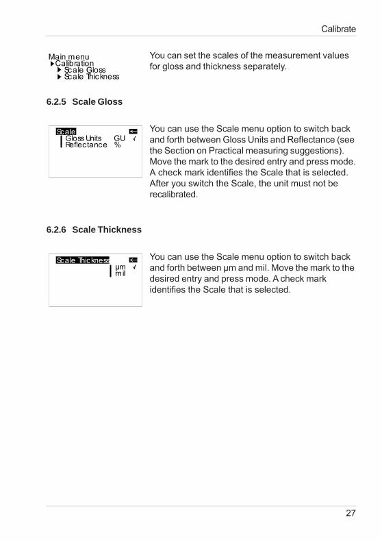
You can set the scales of the measurement valuesfor gloss and thickness separately.
6.2.5 Scale Gloss
You can use the Scale menu option to switch backand forth between Gloss Units and Reflectance (seethe Section on Practical measuring suggestions).Move the mark to the desired entry and press mode.A check mark identifies the Scale that is selected.After you switch the Scale, the unit must not berecalibrated.
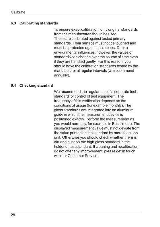
6.2.6 Scale Thickness
You can use the Scale menu option to switch backand forth between μm and mil. Move the mark to thedesired entry and press mode. A check markidentifies the Scale that is selected.
28
Calibrate
6.3 Calibrating standardsTo ensure exact calibration, only original standardsfrom the manufacturer should be used.These are calibrated against tested primarystandards. Their surface must not be touched andmust be protected against scratches. Due toenvironmental influences, however, the values ofstandards can change over the course of time evenif they are handled gently. For this reason, youshould have the calibration standards tested by themanufacturer at regular intervals (we recommendannually).
6.4 Checking standardWe recommend the regular use of a separate teststandard for control of test equipment. Thefrequency of this verification depends on theconditions of usage (for example monthly). Thegloss standards are integrated into an aluminumguide in which the measurement device ispositioned exactly. Perform the measurement asyou would normally, for example in Basic mode. Thedisplayed measurement value must not deviate fromthe value printed on the standard by more than oneunit. Otherwise you should check whether there isdirt and dust on the high gloss standard in theholder or test standard. If cleaning and recalibrationdo not offer any improvement, please get in touchwith our Customer Service.
29
Measurement techniques
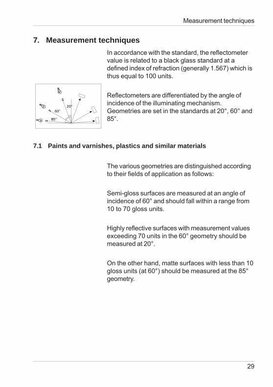
7. Measurement techniquesIn accordance with the standard, the reflectometervalue is related to a black glass standard at adefined index of refraction (generally 1.567) which isthus equal to 100 units.
Reflectometers are differentiated by the angle ofincidence of the illuminating mechanism.Geometries are set in the standards at 20°, 60° and85°.
7.1 Paints and varnishes, plastics and similar materials
The various geometries are distinguished accordingto their fields of application as follows:
Semi-gloss surfaces are measured at an angle ofincidence of 60° and should fall within a range from10 to 70 gloss units.
Highly reflective surfaces with measurement valuesexceeding 70 units in the 60° geometry should bemeasured at 20°.
On the other hand, matte surfaces with less than 10gloss units (at 60°) should be measured at the 85°geometry.
30
Measurement techniques
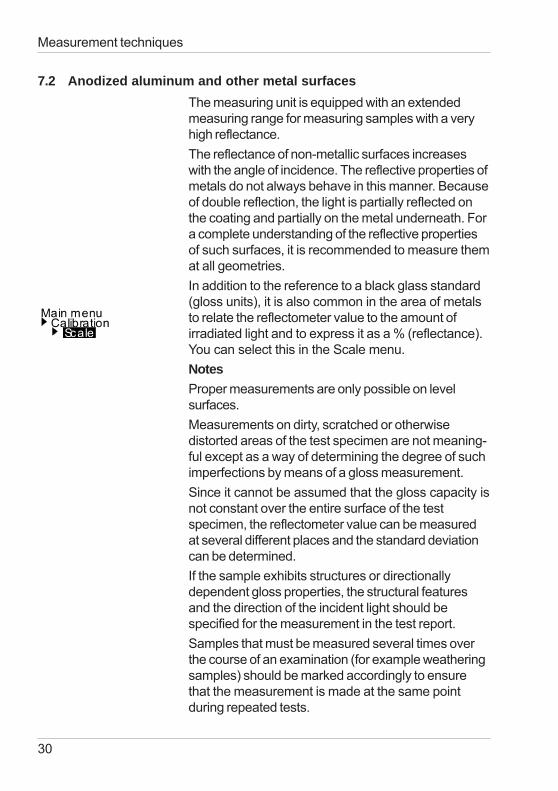
7.2 Anodized aluminum and other metal surfacesThe measuring unit is equipped with an extendedmeasuring range for measuring samples with a veryhigh reflectance.The reflectance of non-metallic surfaces increaseswith the angle of incidence. The reflective properties ofmetals do not always behave in this manner. Becauseof double reflection, the light is partially reflected onthe coating and partially on the metal underneath. Fora complete understanding of the reflective propertiesof such surfaces, it is recommended to measure themat all geometries.In addition to the reference to a black glass standard(gloss units), it is also common in the area of metalsto relate the reflectometer value to the amount ofirradiated light and to express it as a % (reflectance).You can select this in the Scale menu.NotesProper measurements are only possible on levelsurfaces.Measurements on dirty, scratched or otherwisedistorted areas of the test specimen are not meaning-ful except as a way of determining the degree of suchimperfections by means of a gloss measurement.Since it cannot be assumed that the gloss capacity isnot constant over the entire surface of the testspecimen, the reflectometer value can be measuredat several different places and the standard deviationcan be determined.If the sample exhibits structures or directionallydependent gloss properties, the structural featuresand the direction of the incident light should bespecified for the measurement in the test report.Samples that must be measured several times overthe course of an examination (for example weatheringsamples) should be marked accordingly to ensurethat the measurement is made at the same pointduring repeated tests.
31
7.3 Measurement of film thicknessThe film thickness sensor functions according to themagnetic method (Fe) or the eddy current method(NFe). Therefore, the measurement results can bedistorted by strong magnetic fields or electro-magnetic radiation.The measurement of film thickness is influenced bythe thickness and magnetic (Fe) or electrical (NFe)properties of the basis metal.The measurement results can thus be distorted bysuch factors as the composition or heat treatment ofthe substrate. It is therefore advisable to perform thezero calibration on the uncoated metal which isused for the object to be measured.Surface roughness also influences the measure-ment of the coating thickness. To reduce randomerrors, multiple measurements are recommended.If the paint film thickness is to be measured using amagnetic substrate coated with a non-ironmetal (e.g. zinc plated steel sheet), the followingmust be noted:• For the NFe setting, the thickness of thesubstrate, i.e. of the non-magnetic coating, must beat least 50 μm.• With the Fe setting, the thickness of the non-magnetic coating is included in the measurementresult.
Measurement techniques
32
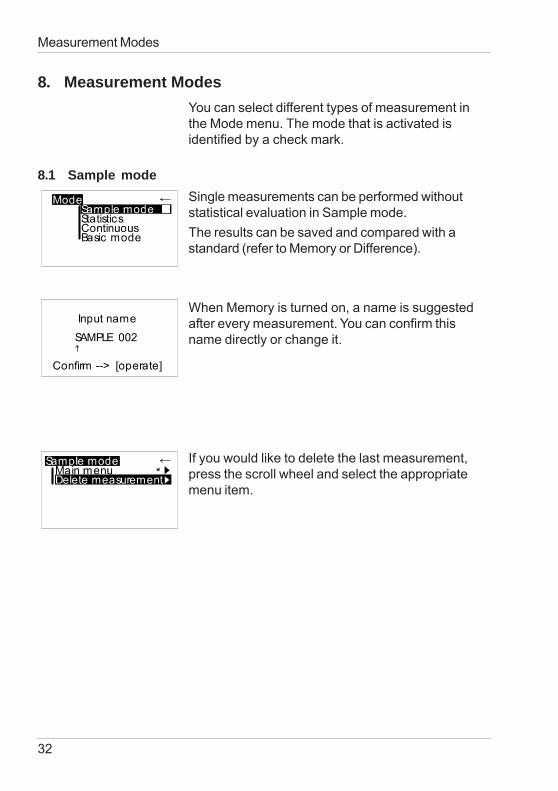
8. Measurement ModesYou can select different types of measurement inthe Mode menu. The mode that is activated isidentified by a check mark.
8.1 Sample modeSingle measurements can be performed withoutstatistical evaluation in Sample mode.The results can be saved and compared with astandard (refer to Memory or Difference).
When Memory is turned on, a name is suggestedafter every measurement. You can confirm thisname directly or change it.
If you would like to delete the last measurement,press the scroll wheel and select the appropriatemenu item.
Measurement Modes
33
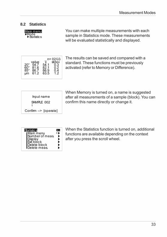
8.2 StatisticsYou can make multiple measurements with eachsample in Statistics mode. These measurementswill be evaluated statistically and displayed.
The results can be saved and compared with astandard. These functions must be previouslyactivated (refer to Memory or Difference).
Measurement Modes
When Memory is turned on, a name is suggestedafter all measurements of a sample (block). You canconfirm this name directly or change it.
When the Statistics function is turned on, additionalfunctions are available depending on the contextafter you press the scroll wheel.
34
Measurement Modes
Note:(micro-TRI-gloss μ only)When STATISTICS is activated, all film thicknessvalues are stored in the Memory independently ofthe sonde used.In the case of an incorrect substrate or a high filmthickness, “Infi“ is written to the memory.When the instrument is switched off, the last settingremains active.
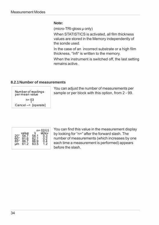
8.2.1Number of measurementsYou can adjust the number of measurements persample or per block with this option, from 2 - 99.
You can find this value in the measurement displayby looking for “n=” after the forward slash. Thenumber of measurements (which increases by oneeach time a measurement is performed) appearsbefore the slash.
35
Measurement Modes
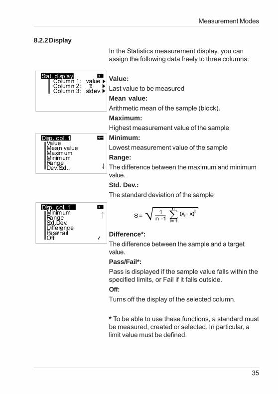
8.2.2DisplayIn the Statistics measurement display, you canassign the following data freely to three columns:
Value:Last value to be measuredMean value:Arithmetic mean of the sample (block).Maximum:Highest measurement value of the sampleMinimum:Lowest measurement value of the sampleRange:The difference between the maximum and minimumvalue.Std. Dev.:The standard deviation of the sample
Difference*:The difference between the sample and a targetvalue.Pass/Fail*:Pass is displayed if the sample value falls within thespecified limits, or Fail if it falls outside.Off:Turns off the display of the selected column.
* To be able to use these functions, a standard mustbe measured, created or selected. In particular, alimit value must be defined.
36
Measurement Modes
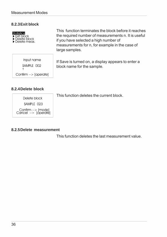
8.2.3Exit blockThis function terminates the block before it reachesthe required number of measurements n. It is usefulif you have selected a high number ofmeasurements for n, for example in the case oflarge samples.
If Save is turned on, a display appears to enter ablock name for the sample.
8.2.4Delete blockThis function deletes the current block.
8.2.5Delete measurementThis function deletes the last measurement value.
37
Measurement Modes
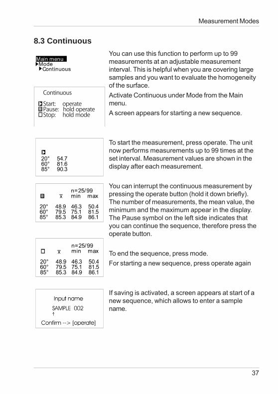
8.3 ContinuousYou can use this function to perform up to 99measurements at an adjustable measurementinterval. This is helpful when you are covering largesamples and you want to evaluate the homogeneityof the surface.Activate Continuous under Mode from the Mainmenu.A screen appears for starting a new sequence.
To start the measurement, press operate. The unitnow performs measurements up to 99 times at theset interval. Measurement values are shown in thedisplay after each measurement.
You can interrupt the continuous measurement bypressing the operate button (hold it down briefly).The number of measurements, the mean value, theminimum and the maximum appear in the display.The Pause symbol on the left side indicates thatyou can continue the sequence, therefore press theoperate button.
To end the sequence, press mode.For starting a new sequence, press operate again
If saving is activated, a screen appears at start of anew sequence, which allows to enter a samplename.
38
Measurement Modes
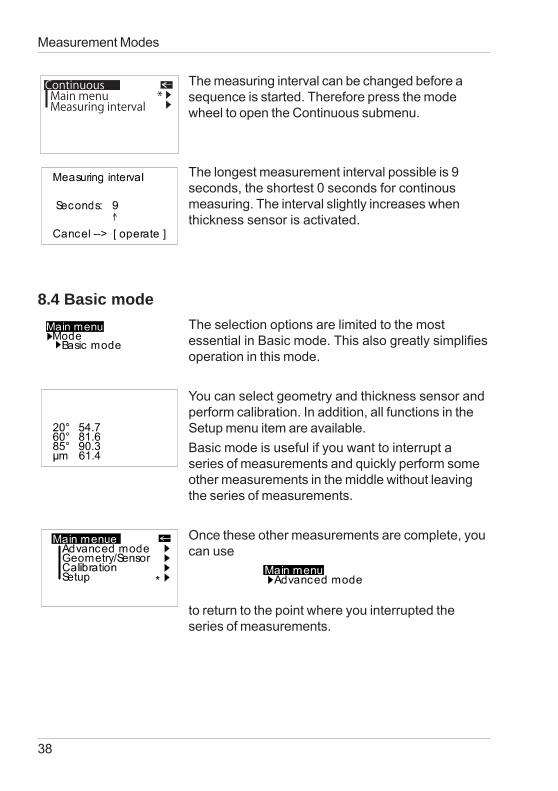
The measuring interval can be changed before asequence is started. Therefore press the modewheel to open the Continuous submenu.
The longest measurement interval possible is 9seconds, the shortest 0 seconds for continousmeasuring. The interval slightly increases whenthickness sensor is activated.
8.4 Basic modeThe selection options are limited to the mostessential in Basic mode. This also greatly simplifiesoperation in this mode.
You can select geometry and thickness sensor andperform calibration. In addition, all functions in theSetup menu item are available.Basic mode is useful if you want to interrupt aseries of measurements and quickly perform someother measurements in the middle without leavingthe series of measurements.
Once these other measurements are complete, youcan use
to return to the point where you interrupted theseries of measurements.
ContinuousMain menuMeasuring interval
*
39
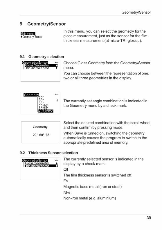
9 Geometry/SensorIn this menu, you can select the geometry for thegloss measurement, just as the sensor for the filmthickness measurement (at micro-TRI-gloss μ).
9.1 Geometry selectionChoose Gloss Geometry from the Geometry/Sensormenu.You can choose between the representation of one,two or all three geometries in the display.
The currently set angle combination is indicated inthe Geometry menu by a check mark.
Select the desired combination with the scroll wheeland then confirm by pressing mode.When Save is turned on, switching the geometryautomatically causes the program to switch to theappropriate predefined area of memory.
9.2 Thickness Sensor selectionThe currently selected sensor is indicated in thedisplay by a check mark.OffThe film thickness sensor is switched off.FeMagnetic base metal (iron or steel)NFeNon-iron metal (e.g. aluminium)
Geometry/Sensor
40
Geometry/Sensor
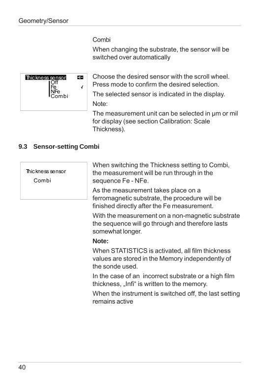
CombiWhen changing the substrate, the sensor will beswitched over automatically
Choose the desired sensor with the scroll wheel.Press mode to confirm the desired selection.The selected sensor is indicated in the display.Note:The measurement unit can be selected in μm or milfor display (see section Calibration: ScaleThickness).
9.3 Sensor-setting Combi
When switching the Thickness setting to Combi,the measurement will be run through in thesequence Fe - NFe.As the measurement takes place on aferromagnetic substrate, the procedure will befinished directly after the Fe measurement.With the measurement on a non-magnetic substratethe sequence will go through and therefore lastssomewhat longer.Note:When STATISTICS is activated, all film thicknessvalues are stored in the Memory independently ofthe sonde used.In the case of an incorrect substrate or a high filmthickness, „Infi“ is written to the memory.When the instrument is switched off, the last settingremains active
41
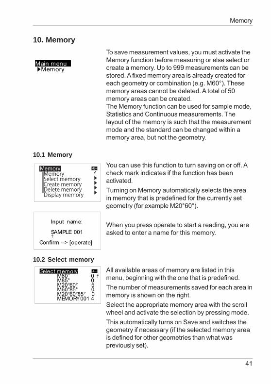
10. MemoryTo save measurement values, you must activate theMemory function before measuring or else select orcreate a memory. Up to 999 measurements can bestored. A fixed memory area is already created foreach geometry or combination (e.g. M60°). Thesememory areas cannot be deleted. A total of 50memory areas can be created.The Memory function can be used for sample mode,Statistics and Continuous measurements. Thelayout of the memory is such that the measurementmode and the standard can be changed within amemory area, but not the geometry.
10.1 MemoryYou can use this function to turn saving on or off. Acheck mark indicates if the function has beenactivated.Turning on Memory automatically selects the areain memory that is predefined for the currently setgeometry (for example M20°60°).
When you press operate to start a reading, you areasked to enter a name for this memory.
10.2 Select memoryAll available areas of memory are listed in thismenu, beginning with the one that is predefined.The number of measurements saved for each area inmemory is shown on the right.Select the appropriate memory area with the scrollwheel and activate the selection by pressing mode.This automatically turns on Save and switches thegeometry if necessary (if the selected memory areais defined for other geometries than what waspreviously set).
Memory
MemoryMemorySelect memoryCreate memoryDelete memoryDisplay memory
42
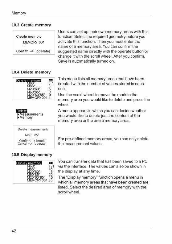
10.3 Create memoryUsers can set up their own memory areas with thisfunction. Select the required geometry before youactivate this function. Then you must enter thename of a memory area. You can confirm thesuggested name directly with the operate button orchange it with the scroll wheel. After you confirm,Save is automatically turned on.
10.4 Delete memoryThis menu lists all memory areas that have beencreated with the number of values stored in eachone.Use the scroll wheel to move the mark to thememory area you would like to delete and press thewheel.A menu appears in which you can decide whetheryou would like to delete just the content of thememory area or the entire memory area.
For pre-defined memory areas, you can only deletethe measurement values.
10.5 Display memoryYou can transfer data that has been saved to a PCvia the interface. The values can also be shown inthe display at any time.The “Display memory” function opens a menu inwhich all memory areas that have been created arelisted. Select the desired area of memory with thescroll wheel.
Memory
Delete measurements
M60°85°
Confirm --> [mode]Cancel --> [operate]
43
Memory
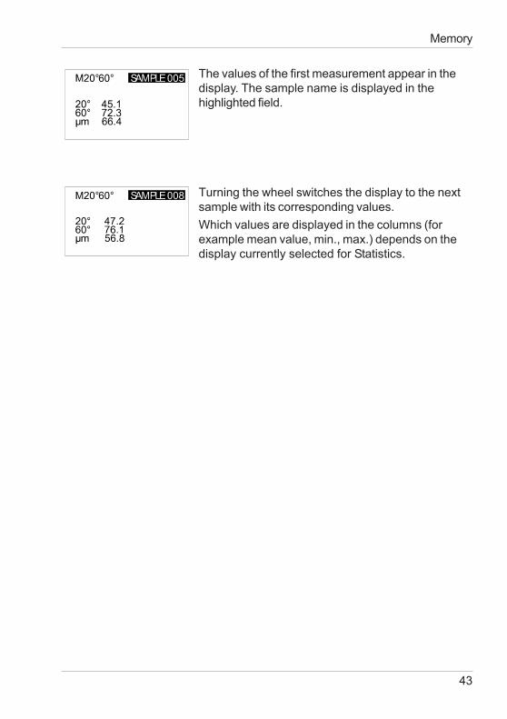
The values of the first measurement appear in thedisplay. The sample name is displayed in thehighlighted field.
Turning the wheel switches the display to the nextsample with its corresponding values.Which values are displayed in the columns (forexample mean value, min., max.) depends on thedisplay currently selected for Statistics.
44
Difference measurement and Pass/Fail
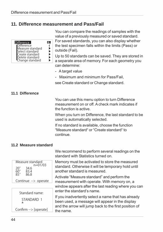
11. Difference measurement and Pass/FailYou can compare the readings of samples with thevalue of a previously measured or saved standard.For saved standards, you can also display whetherthe test specimen falls within the limits (Pass) oroutside (Fail).Up to 50 standards can be saved. They are stored ina separate area of memory. For each geometry youcan determine:- A target value- Maximum and minimum for Pass/Fail,see Create standard or Change standard.
11.1 DifferenceYou can use this menu option to turn Differencemeasurement on or off. A check mark indicates ifthe function is active.When you turn on Difference, the last standard to beused is automatically selected.If no standard is available, choose the function“Measure standard“ or “Create standard“ tocontinue.
11.2 Measure standardWe recommend to perform several readings on thestandard with Statistics turned on.Memory must be activated to store the measuredstandard. Otherwise it will be temporary hold untilanother standard is measured.Activate “Measure standard” and perform themeasurement with operate. With memory on, awindow appears after the last reading where you canenter the standard’s name.If you inadvertently select a name that has alreadybeen used, a message will appear in the displayand the arrow will jump back to the first position ofthe name.
DifferenceDifferenceMeasure standardSelectCreateDeleteChange
standardstandardstandardstandard
Measure standardn=01/03
20° 34.660° 83.485° 86.8
Continue --> operate
Standard name:
STANDARD 1
Confirm --> [operate]
45
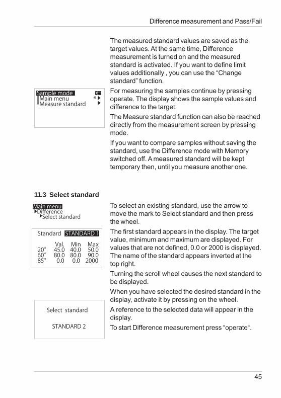
The measured standard values are saved as thetarget values. At the same time, Differencemeasurement is turned on and the measuredstandard is activated. If you want to define limitvalues additionally , you can use the “Changestandard” function.For measuring the samples continue by pressingoperate. The display shows the sample values anddifference to the target.The Measure standard function can also be reacheddirectly from the measurement screen by pressingmode.If you want to compare samples without saving thestandard, use the Difference mode with Memoryswitched off. A measured standard will be kepttemporary then, until you measure another one.
11.3 Select standardTo select an existing standard, use the arrow tomove the mark to Select standard and then pressthe wheel.The first standard appears in the display. The targetvalue, minimum and maximum are displayed. Forvalues that are not defined, 0.0 or 2000 is displayed.The name of the standard appears inverted at thetop right.Turning the scroll wheel causes the next standard tobe displayed.When you have selected the desired standard in thedisplay, activate it by pressing on the wheel.A reference to the selected data will appear in thedisplay.To start Difference measurement press “operate“.
Difference measurement and Pass/Fail
Sample modeMain menuMeasure standard
*
Main menuDifferenceSelect standard
Standard
Val. Min Max20° 45.0 40.0 50.060° 80.0 80.0 90.085° 0.0 0.0 2000
STANDARD 1
Select standard
STANDARD 2
46
Difference measurement and Pass/Fail
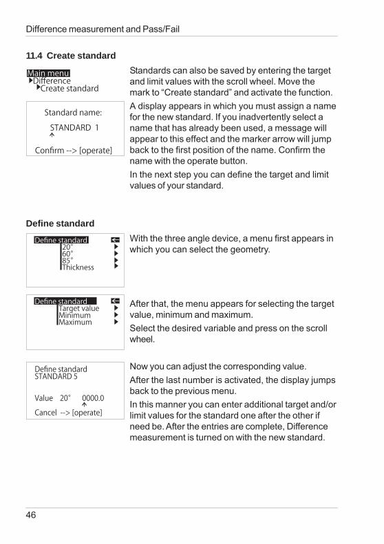
11.4 Create standardStandards can also be saved by entering the targetand limit values with the scroll wheel. Move themark to “Create standard” and activate the function.A display appears in which you must assign a namefor the new standard. If you inadvertently select aname that has already been used, a message willappear to this effect and the marker arrow will jumpback to the first position of the name. Confirm thename with the operate button.In the next step you can define the target and limitvalues of your standard.
Define standardWith the three angle device, a menu first appears inwhich you can select the geometry.
After that, the menu appears for selecting the targetvalue, minimum and maximum.Select the desired variable and press on the scrollwheel.
Now you can adjust the corresponding value.After the last number is activated, the display jumpsback to the previous menu.In this manner you can enter additional target and/orlimit values for the standard one after the other ifneed be. After the entries are complete, Differencemeasurement is turned on with the new standard.
Main menuDifferenceCreate standard
Standard name:
STANDARD 1
Confirm --> [operate]
Define standard20°60°85°Thickness
Define standardTarget valueMinimumMaximum
Define standardSTANDARD 5
Value 20° 0000.0
Cancel --> [operate]
47
Difference measurement and Pass/Fail
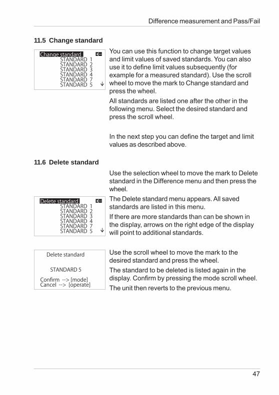
11.5 Change standardYou can use this function to change target valuesand limit values of saved standards. You can alsouse it to define limit values subsequently (forexample for a measured standard). Use the scrollwheel to move the mark to Change standard andpress the wheel.All standards are listed one after the other in thefollowing menu. Select the desired standard andpress the scroll wheel.
In the next step you can define the target and limitvalues as described above.
11.6 Delete standardUse the selection wheel to move the mark to Deletestandard in the Difference menu and then press thewheel.The Delete standard menu appears. All savedstandards are listed in this menu.If there are more standards than can be shown inthe display, arrows on the right edge of the displaywill point to additional standards.
Use the scroll wheel to move the mark to thedesired standard and press the wheel.The standard to be deleted is listed again in thedisplay. Confirm by pressing the mode scroll wheel.The unit then reverts to the previous menu.
Change standardSTANDARD 1STANDARD 2STANDARD 3STANDARD 4STANDARD 7STANDARD 5
Delete standardSTANDARD 1STANDARD 2STANDARD 3STANDARD 4STANDARD 7STANDARD 5
Delete standard
STANDARD 5
Confirm --> [mode]Cancel --> [operate]
48
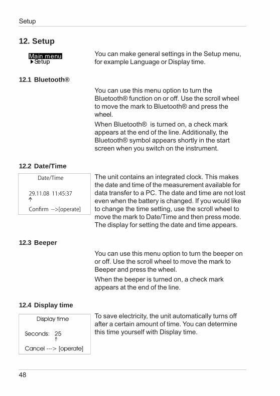
12. SetupYou can make general settings in the Setup menu,for example Language or Display time.
12.1 Bluetooth®You can use this menu option to turn theBluetooth® function on or off. Use the scroll wheelto move the mark to Bluetooth® and press thewheel.When Bluetooth® is turned on, a check markappears at the end of the line. Additionally, theBluetooth® symbol appears shortly in the startscreen when you switch on the instrument.
12.2 Date/TimeThe unit contains an integrated clock. This makesthe date and time of the measurement available fordata transfer to a PC. The date and time are not losteven when the battery is changed. If you would liketo change the time setting, use the scroll wheel tomove the mark to Date/Time and then press mode.The display for setting the date and time appears.
12.3 BeeperYou can use this menu option to turn the beeper onor off. Use the scroll wheel to move the mark toBeeper and press the wheel.When the beeper is turned on, a check markappears at the end of the line.
12.4 Display timeTo save electricity, the unit automatically turns offafter a certain amount of time. You can determinethis time yourself with Display time.
Date/Time
29.11.08 11:45:37
Confirm -->[operate]
Setup
49
InfoCatalog no.Serial no.Version no.Last calib.Last certif.
44461000000V. 12.0011.20.0811.01.08
Setup
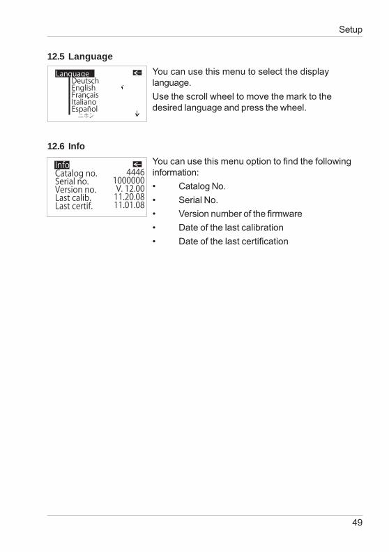
12.5 LanguageYou can use this menu to select the displaylanguage.Use the scroll wheel to move the mark to thedesired language and press the wheel.
12.6 InfoYou can use this menu option to find the followinginformation:• Catalog No.• Serial No.• Version number of the firmware• Date of the last calibration• Date of the last certification
LanguageDeutschEnglishFrançaisItalianoEspañol���
50
Interface
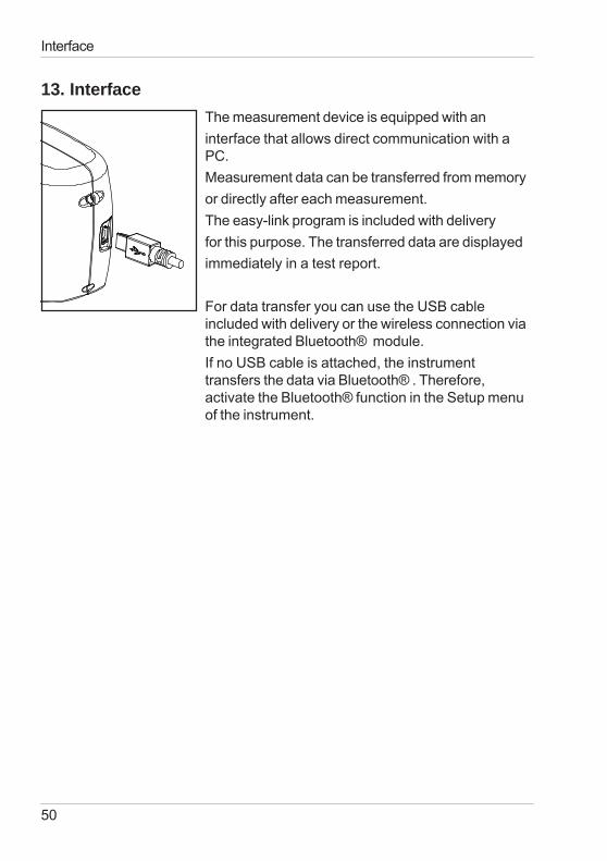
13. InterfaceThe measurement device is equipped with aninterface that allows direct communication with aPC.Measurement data can be transferred from memoryor directly after each measurement.The easy-link program is included with deliveryfor this purpose. The transferred data are displayedimmediately in a test report.
For data transfer you can use the USB cableincluded with delivery or the wireless connection viathe integrated Bluetooth® module.If no USB cable is attached, the instrumenttransfers the data via Bluetooth® . Therefore,activate the Bluetooth® function in the Setup menuof the instrument.
51
13.1 Installation
Bluetooth® :Please refer to the separate Bluetooth® InstallationGuide.Software easy-link and USB drivers:Insert the easy-link CD into the CD drive and run the„setup.exe“ for installation of the program. Followthe instructions on the screen.After installation, the default directory of theappropriate Excel Reports will be “...\bykware\easy-link“.
As you connect the device to the USB port of thecomputer, it is recognized by the system and thehardware assistant opens:1. Choose “Install from a list“ and click the button“Next“. Then select the folder “USB Driver“ from theeasy-link CD. The driver setup begins. Note that if awindow displays a choice of buttons to “ContinueAnyway“ or “Stop Installation“ click on “ContinueAnyway“. Click the “Finish“ button to complete theinstallation of the 1st driver.2. After short time the hardware assistant opens forinstallation of the 2nd driver. Continue theinstallation as described above by following theinstructions.
After the setup is completed for both drivers, openthe gloss-link report from the easy-link folder.
Interface
52
Standards
14. Standards
ISO 2813 Paints and varnishes - Determination of speculargloss of non-metallic paint films at 20°, 60° and 85°
ASTM D 523 Standard Test Method for Specular Gloss
ASTM D 2457 Standard Test Method for Specular Gloss of PlasticFilms and Solid Plastics
DIN 67530 Reflektometer als Hilfsmittel zur Glanzbeurteilung anebenen Anstrich- und Kunststoffoberflächen(Reflectometer as a means for gloss assessment ofplane surfaces of paint coatings and plastics)
BS 3900 - D5 Methods of test for paints. Measurement of speculargloss of non-metallic paint films at 20°, 60° and 85°
JIS Z 8741 Method of Measurement for Specular Glossiness
ISO 7668 Anodized aluminium and aluminium alloys -Measurement of specular reflectance and speculargloss at angles of 20°, 45°, 60° or 85°.
BS 6161 - 12 Methods of test for anodic oxidation coatings onaluminium and its alloys. Measurement of specularreflectance and specular gloss at anglesof 20°, 45°, 60° or 85°.
53
ISO 2178 Non-magnetic coatings on magnetic substrates -Measurement of coating thickness - Magneticmethod
ISO 2360 Non-conductive coatings on non-magnetic electricallyconductive basis materials. Measurement of coatingthickness. Amplitude-sensitive eddy-current method.
ASTM B 499 Measurement of Coating Thicknesses by theMagnetic Method: Nonmagnetic Coatings onMagnetic Basis Metals
ASTM D 1400 Measurement of Dry Film Thickness of NonmetallicCoatings of Paint, Varnish, Lacquer, and RelatedProducts applied on a Nonmagnetic Metal Base
Standards
54
Technical data
15. Technical data
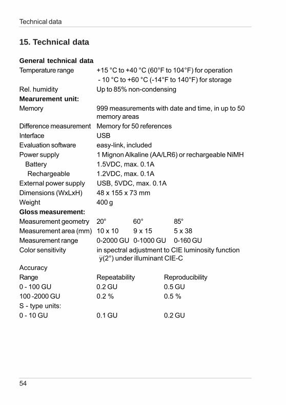
General technical dataTemperature range +15 °C to +40 °C (60°F to 104°F) for operation
- 10 °C to +60 °C (-14°F to 140°F) for storageRel. humidity Up to 85% non-condensingMearurement unit:Memory 999 measurements with date and time, in up to 50
memory areasDifference measurement Memory for 50 referencesInterface USBEvaluation software easy-link, includedPower supply 1 Mignon Alkaline (AA/LR6) or rechargeable NiMH Battery 1.5VDC, max. 0.1A Rechargeable 1.2VDC, max. 0.1AExternal power supply USB, 5VDC, max. 0.1ADimensions (WxLxH) 48 x 155 x 73 mmWeight 400 gGloss measurement:Measurement geometry 20° 60° 85°Measurement area (mm) 10 x 10 9 x 15 5 x 38Measurement range 0-2000 GU 0-1000 GU 0-160 GUColor sensitivity in spectral adjustment to CIE luminosity function
(2°) under illuminant CIE-CAccuracyRange Repeatability Reproducibility0 - 100 GU 0.2 GU 0.5 GU100 -2000 GU 0.2 % 0.5 %S - type units:0 - 10 GU 0.1 GU 0.2 GU
55
Technical data
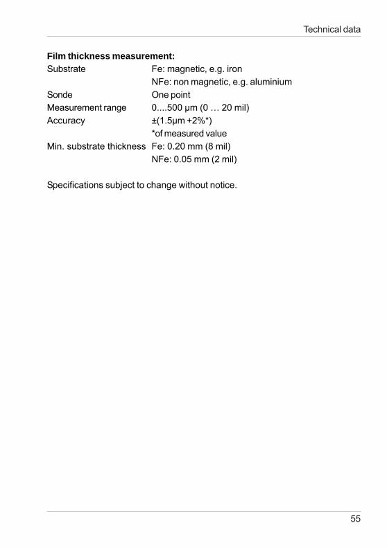
Film thickness measurement:Substrate Fe: magnetic, e.g. iron
NFe: non magnetic, e.g. aluminiumSonde One pointMeasurement range 0....500 μm (0 … 20 mil)Accuracy ±(1.5μm +2%*)
*of measured valueMin. substrate thickness Fe: 0.20 mm (8 mil)
NFe: 0.05 mm (2 mil)
Specifications subject to change without notice.
56
Errors and warning messages
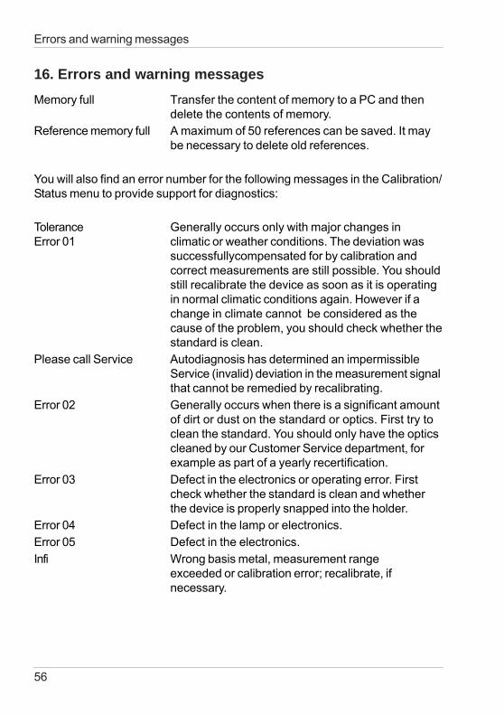
16. Errors and warning messagesMemory full Transfer the content of memory to a PC and then
delete the contents of memory.Reference memory full A maximum of 50 references can be saved. It may
be necessary to delete old references.
You will also find an error number for the following messages in the Calibration/Status menu to provide support for diagnostics:
Tolerance Generally occurs only with major changes inError 01 climatic or weather conditions. The deviation was
successfullycompensated for by calibration andcorrect measurements are still possible. You shouldstill recalibrate the device as soon as it is operatingin normal climatic conditions again. However if achange in climate cannot be considered as thecause of the problem, you should check whether thestandard is clean.
Please call Service Autodiagnosis has determined an impermissibleService (invalid) deviation in the measurement signalthat cannot be remedied by recalibrating.
Error 02 Generally occurs when there is a significant amountof dirt or dust on the standard or optics. First try toclean the standard. You should only have the opticscleaned by our Customer Service department, forexample as part of a yearly recertification.
Error 03 Defect in the electronics or operating error. Firstcheck whether the standard is clean and whetherthe device is properly snapped into the holder.
Error 04 Defect in the lamp or electronics.Error 05 Defect in the electronics.Infi Wrong basis metal, measurement range
exceeded or calibration error; recalibrate, ifnecessary.
57
Errors and warning messages
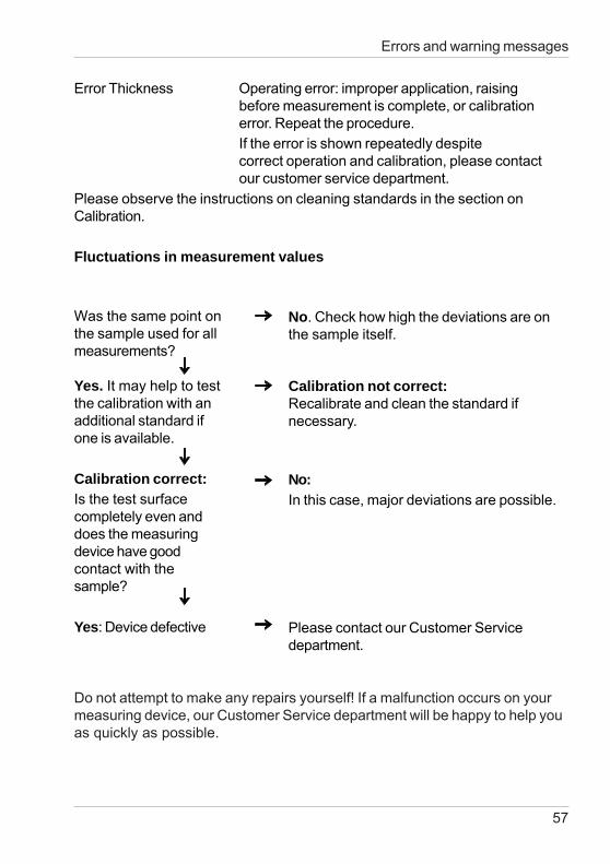
Error Thickness Operating error: improper application, raisingbefore measurement is complete, or calibrationerror. Repeat the procedure.If the error is shown repeatedly despitecorrect operation and calibration, please contactour customer service department.
Please observe the instructions on cleaning standards in the section onCalibration.
Fluctuations in measurement values
Was the same point onthe sample used for allmeasurements?
Yes. It may help to testthe calibration with anadditional standard ifone is available.
Calibration correct:Is the test surfacecompletely even anddoes the measuringdevice have goodcontact with thesample?
Yes: Device defective
No. Check how high the deviations are onthe sample itself.
Calibration not correct:Recalibrate and clean the standard ifnecessary.
No:In this case, major deviations are possible.
Please contact our Customer Servicedepartment.
Do not attempt to make any repairs yourself! If a malfunction occurs on yourmeasuring device, our Customer Service department will be happy to help youas quickly as possible.
58
17. Cleaning and maintenance
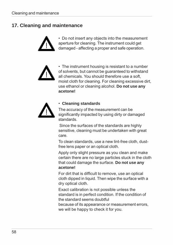
• Do not insert any objects into the measurementaperture for cleaning. The instrument could getdamaged - affecting a proper and safe operation.
• The instrument housing is resistant to a numberof solvents, but cannot be guaranteed to withstandall chemicals. You should therefore use a soft,moist cloth for cleaning. For cleaning excessive dirt,use ethanol or cleaning alcohol. Do not use anyacetone!
• Cleaning standardsThe accuracy of the measurement can besignificantly impacted by using dirty or damagedstandards. Since the surfaces of the standards are highlysensitive, cleaning must be undertaken with greatcare.To clean standards, use a new lint-free cloth, dust-free lens paper or an optical cloth.Apply only slight pressure as you clean and makecertain there are no large particles stuck in the cloththat could damage the surface. Do not use anyacetone!For dirt that is difficult to remove, use an opticalcloth dipped in liquid. Then wipe the surface with adry optical cloth.Exact calibration is not possible unless thestandard is in perfect condition. If the condition ofthe standard seems doubtfulbecause of its appearance or measurement errors,we will be happy to check it for you.
Cleaning and maintenance
59
18. Service and Certification
ServiceBesides the repair of your instrument we offer thefollowing additional services:First diagnosis on the telephone or by e-mailCall us or send us an e-mail and we will try to solveyour problem. If this is not successful, please sendus the instrument for repair.Preventive maintenance, calibration, andrecertificationFor precautionary reasons we recommend regularpreventive maintenance. We carry out this preventivemaintenance automatically when you send us yourinstrument for maintenance and recertification. Weclean the optics, check all functions, test and, ifrequired, adjust the measured values by usingreference standards. You will receive a certificate,which includes the retraceability to internationalstandards.LoanersDuring the period of repair we furnish you with aloaner on request and availability.Maintenance agreementIn case you want to make sure that the necessarymaintenance is being done on a regular basis andon time, we recommend a maintenance agreement.Extended warranty contractsFurthermore, you can request an extended warrantycontract for additional 12 months.
Ordering information:
SP-4440 Calibration serviceSE-4440 Extended warranty
Service and Certification
60
Service and Certification
Service Centers for BYK-Gardner products
GermanyBYK-Gardner GmbHLausitzer Strasse 882538 GeretsriedGermanyPhone:+49-8171-3493-0Fax: +49-8171-3493-166
USABYK-Gardner USA9104 Guilford RoadColumbia, MD 21046USAPhone:+1-301-483-6500Fax: +1-301-483-6555
ChinaBYK-Gardner Shanghai OfficeRoom 1407, SIPAI PLAZA103, Cao Bao RoadShanghai 200233P.R. ChinaPhone: +86-21 -6475-8570Fax: +86-21-6475-7284
BrazilBYK-Gardner Latin AmericaRua das Aroeiras, 771Bairro Jardim-Santo André-SPCEP 09090-000BrazilPhone:+55-11-2147-1199Fax: +55-11-2147-1168
61
19. Copyright
This instruction manual is an important part of this instrument. It contains es-sential information about setting up, placing in service and use. If you passthe device on to another user, please ensure that the instruction manual isincluded with the instrument. The manual must be studied carefully beforeworking with the equipment. Please contact your regional service office ifyou have any questions or require additional information about the device.
The technology and fittings are based on state-of-the art optic andelectronic technology. New developments and innovations are constantlybeing integrated into the equipment. Thus, the diagrams, dimensions, andtechnical data used in this manual may have changed as a result of adaptingthe device to new information and improvements.
© Copyright 2008 BYK-Gardner GmbHAll rights reserved
No portion of the software, documentation or other accompanying materialsmay be translated, modified, reproduced, copied or otherwise duplicated(with the exception of a backup copy), or distributed to a third party, withoutprior written authorization from BYK-Gardner GmbH. In any case, thisrequires the prior written consent of BYK-Gardner.
BYK-Gardner GmbH offers no guarantee that the software will functionwithout error or that the functions incorporated therein can be executed in allapplications and combinations selected by you.
No liability other than as provided by law is assumed for direct or indirectdamage sustained in association with the use of the instrument, the softwareor documentation.
BYK-Gardner GmbH reserves the right to update the software and writtendocumentation without prior notice.
Copyright

260 020 398 E 0812