Embed Size (px)
Citation preview
Bruker BioSpin
BVT3200
think forw
Variable Temperature Unit for BSMS/2
Technical ManualNard
Versio
n 002MR Spectroscopy
The information in this manual may be altered without notice.
BRUKER BIOSPIN accepts no responsibility for actions taken as a result of use of this manual. BRUKER BIOSPIN accepts no liability for any mistakes contained in the manual, leading to coincidental damage, whether during installation or operation of the instrument. Unauthorised reproduction of manual contents, without written permission from the publishers, or translation into an other language, either the entire manual or a part of it, is forbidden.
This manual describes the units as they are at the date of printing. On request, the manufacturer shall supply circuit diagrams, lists of components, descriptions, calibrating instructions and any other information for use by qualified personnel of the user, in charge of repairing the parts of the unit which have been stated by the manufacturer to be "repairable". Such supply shall in no event constitute permission to modify or repair the units or approval of the same.
All rights reserved for the units, circuits, processes and appellations mentioned herein.
This unit is not designed for any type of use which is not specifically described in this manual. Such use may be hazardous.
This manual was written by
Patrick Krencker and Daniel Podadera
This manual was edited and desktop published by
Karine Hollender and Dominique Wurtz
© January 13, 2009: Bruker BioSpin SA
Wissembourg, France
P/N: Z31544DWG-Nr: 1251.002
For further technical assistance on the BVT3200 unit, please do not hesitate to contact your nearest BRUKER dealer or contact us directly at:
BRUKER BioSpin SA 34 rue de l’Industrie F-67166 Wissembourg Cedex France Phone: + 33 388 066 000 Fax: + 33 388 736 820 Email: [email protected] Internet: www.bruker.com
Contents
Contents ............................................................................ 3
1 Description ......................................................................... 51.1 Introduction ........................................................................................ 51.2 BVT3200 main components ................................................................ 71.3 Parts location ..................................................................................... 71.4 Principle of operation .......................................................................... 71.5 The front panel ................................................................................... 8
Front panel description : ............................................................ 81.6 Gas flow circuit ................................................................................... 9
Setting up the default gas flow ....................................................... 91.7 Front panel connectors ..................................................................... 11
Heater connector ......................................................................... 11PT100 connector .......................................................................... 11Thermocouple connector .............................................................. 12RS232 connector ......................................................................... 13N2 connector (option) ................................................................... 13BCU05 connector ......................................................................... 14BVTB 3500 connector .................................................................. 14
2 Options ............................................................................. 172.1 Low temperature options .................................................................. 172.2 LN2 exchanger ................................................................................. 17
Exchanger presentation ............................................................... 18Exchanger installation .................................................................. 18
2.3 LN2 evaporator ................................................................................. 19Evaporator presentation ............................................................... 19Evaporator installation ................................................................. 20Printed circuit installation ............................................................. 20
2.4 BCU05 gas cooler ............................................................................ 22
3 Configuration ................................................................... 233.1 Sensor selection ............................................................................... 233.2 Eurotherm 2416 configuration ........................................................... 23
4 Remote interface control ................................................. 254.1 Microcontroller interface ................................................................... 254.2 Digital interface specifications .......................................................... 254.3 Commands and communication protocol ........................................... 264.4 Control characters ............................................................................ 264.5 List of commands ............................................................................. 274.6 RS232 link characteristics ................................................................ 28
Technical Manual Version 002 BRUKER BIOSPIN 3 (55)
Contents
4.7 RS232 cable .................................................................................... 284.8 Authorised functions ......................................................................... 29
AF - Air Flow ............................................................................... 30CM - Check Memory (for test only) .............................................. 31CO - Communications Speed ....................................................... 31DL - Download ............................................................................. 32DT - DAC Check (for test only) .................................................... 32ES - Error Status ......................................................................... 33HP - Heater Power ...................................................................... 34IS - Interface Status ..................................................................... 35NH - Nitrogen Heater ................................................................... 36NP - Nitrogen Heater Power ........................................................ 37P1 - Port 1 (for test only) ............................................................. 38P2 - Port 2 (for test only) ............................................................. 39P3 - Port 3 (for test only) ............................................................. 40P4 - Port 4 (for test only) ............................................................. 41RB - Read BBIS .......................................................................... 42SV - Software Version .................................................................. 43WB - Write BBIS .......................................................................... 44WR - Write Record ...................................................................... 45XR (Extract a record) ................................................................... 46
5 Technical specifications ...................................................475.1 Specifications ................................................................................... 475.2 Safety fuses ..................................................................................... 48
Figures ............................................................................. 49
Tables ............................................................................... 51
Index ................................................................................. 53
4 (55) BRUKER BIOSPIN Technical Manual Version 002
1Description 1
Introduction 1.1
The new BVT3200 (P/N: W1101264) is a small size variable temperature unit on single double europe size board.
It has microcontroller interface for remote control by the host computer.
The unit includes:
• A temperature controller (EUROTHERM model 2416).
• The microcontroller and its electronics and the power electronics for the probe heater.
• A gas flow circuitry (pressure regulator and a block of four valves for gas flow control).
The unit is ready to receive an option board for low temperature - LN2 evaporator or heat exchanger.
The BVT3200 is supplied by the general power supply of the BSMS/2 crate. The power stage is supplied by an additional 48 V power supply board.
Technical Manual Version 002 BRUKER BIOSPIN 5 (55)
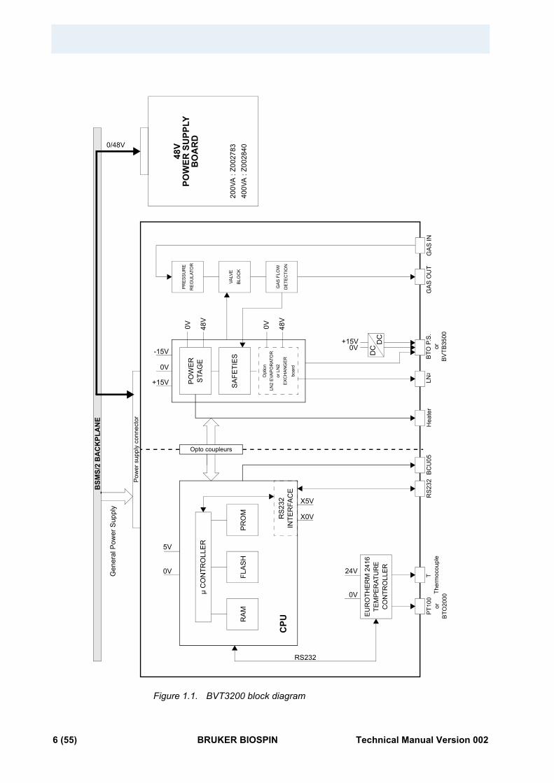
Figure 1.1. BVT3200 block diagram
0/48V
CPU
µ C
ON
TRO
LLE
R
RA
MFL
AS
HP
RO
M RS
232
INTE
RFA
CE
Pow
er s
uppl
y co
nnec
tor
PO
WE
R
Opt
ion
LN2
EVA
POR
ATO
Ror
LN
2EX
CH
ANG
ER
boar
d
Opto coupleurs
5V
0V
24V
EU
RO
THE
RM
241
6TE
MP
ER
ATU
RE
CO
NTR
OLL
ER
BSM
S/2
BA
CK
PLA
NE
48V
POW
ER S
UPP
LYB
OA
RD
0V 48V
PRES
SU
RE
RE
GU
LATO
R
VALV
E
BLO
CK
GAS
FLO
W
DE
TEC
TIO
N
0V 48V
DC
DC
GA
S O
UT
GA
S IN
BTO
P.S
.LN
2H
eate
rB
CU
05R
S232
T PT
100
Gen
eral
Pow
er S
uppl
y
orB
TO20
00or
STA
GE
SA
FETI
ES
X0V
X5V
Ther
moc
oupl
e
RS232
200V
A :
Z002
783
400V
A :
Z002
840
0V+15V
+15V
0V
-15V
0V
BV
TB35
00
6 (55) BRUKER BIOSPIN Technical Manual Version 002
BVT3200 main components
BVT3200 main components 1.2
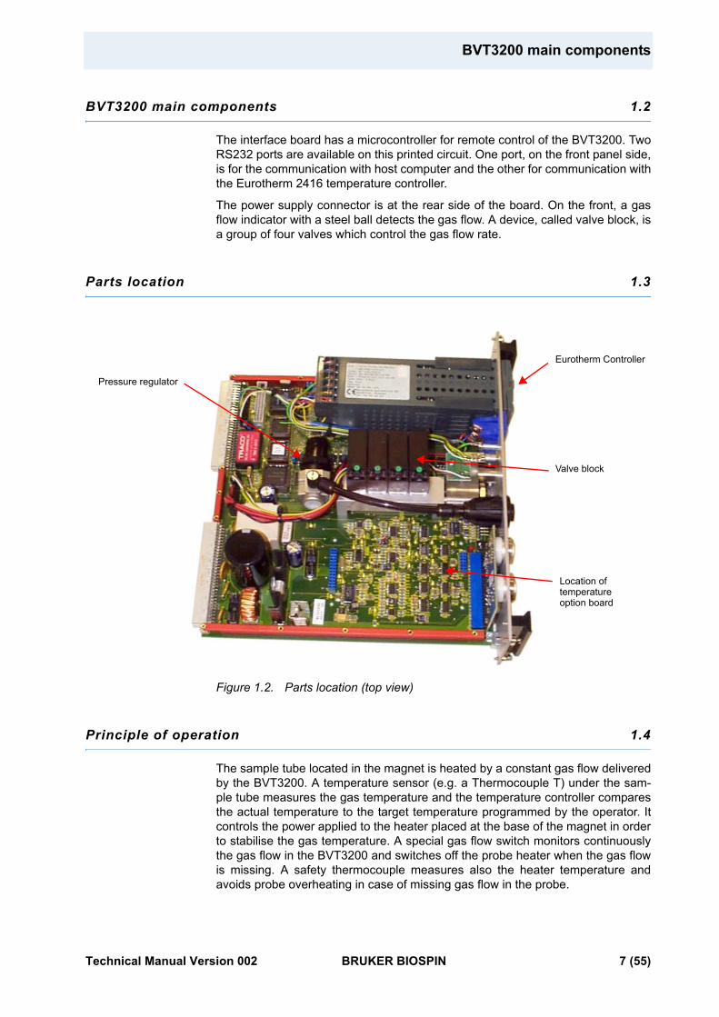
The interface board has a microcontroller for remote control of the BVT3200. Two RS232 ports are available on this printed circuit. One port, on the front panel side, is for the communication with host computer and the other for communication with the Eurotherm 2416 temperature controller.
The power supply connector is at the rear side of the board. On the front, a gas flow indicator with a steel ball detects the gas flow. A device, called valve block, is a group of four valves which control the gas flow rate.
Parts location 1.3
Figure 1.2. Parts location (top view)
Principle of operation 1.4
The sample tube located in the magnet is heated by a constant gas flow delivered by the BVT3200. A temperature sensor (e.g. a Thermocouple T) under the sam-ple tube measures the gas temperature and the temperature controller compares the actual temperature to the target temperature programmed by the operator. It controls the power applied to the heater placed at the base of the magnet in order to stabilise the gas temperature. A special gas flow switch monitors continuously the gas flow in the BVT3200 and switches off the probe heater when the gas flow is missing. A safety thermocouple measures also the heater temperature and avoids probe overheating in case of missing gas flow in the probe.
Pressure regulator
Eurotherm Controller
Valve block
Location oftemperatureoption board
Technical Manual Version 002 BRUKER BIOSPIN 7 (55)
The front panel 1.5
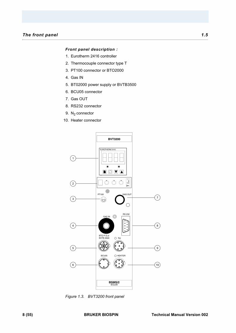
Front panel description :1. Eurotherm 2416 controller
2. Thermocouple connector type T
3. PT100 connector or BTO2000
4. Gas IN
5. BT02000 power supply or BVTB3500
6. BCU05 connector
7. Gas OUT
8. RS232 connector
9. N2 connector
10. Heater connector
Figure 1.3. BVT3200 front panel
7
8
9
10
1
2
3
4
5
6
RS 232
GAS OUT
GAS IN
PT100
BVTB 3500BTO P.S.or
BCU05
N2
HEATER
EUROTHERM 2416
TC
PC
ON
ST
-+
BSMS/2ECL00
BVT3200
8 (55) BRUKER BIOSPIN Technical Manual Version 002
Gas flow circuit
Gas flow circuit 1.6
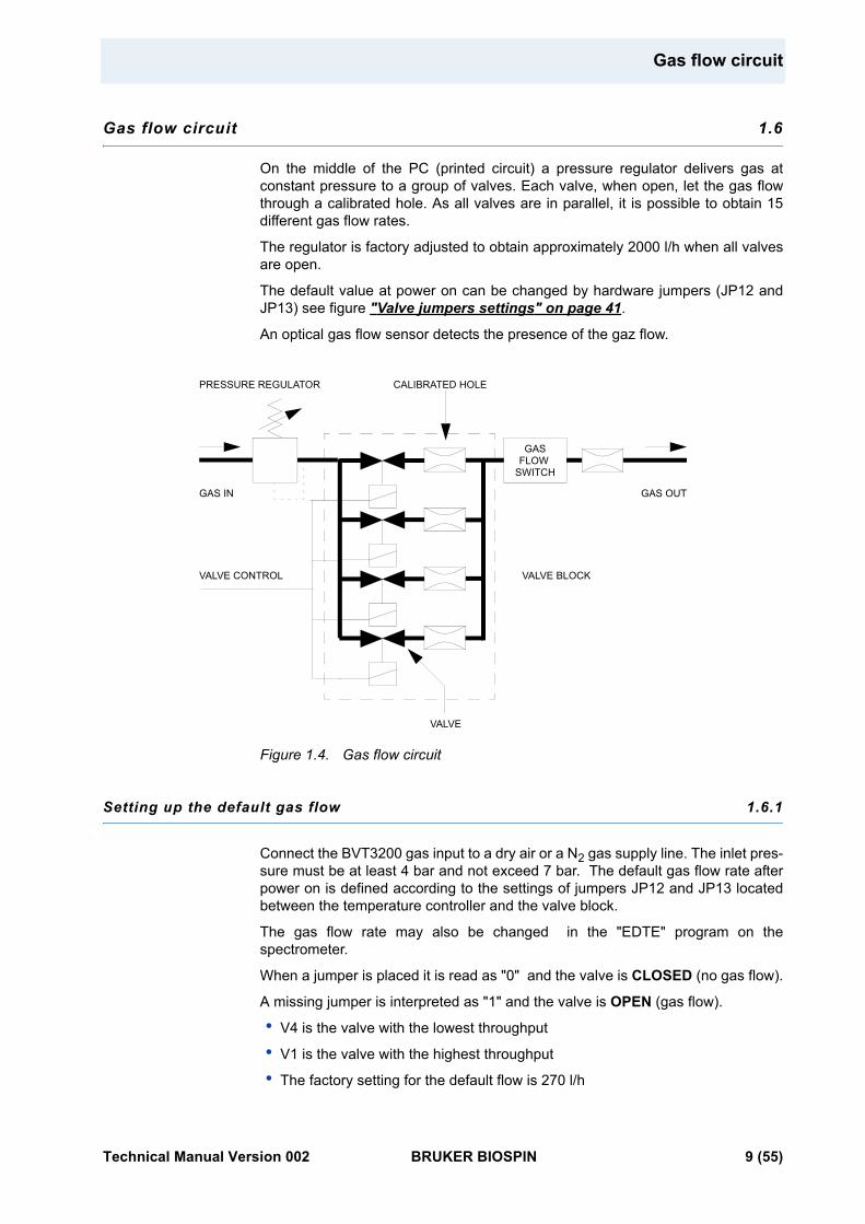
On the middle of the PC (printed circuit) a pressure regulator delivers gas at constant pressure to a group of valves. Each valve, when open, let the gas flow through a calibrated hole. As all valves are in parallel, it is possible to obtain 15 different gas flow rates.
The regulator is factory adjusted to obtain approximately 2000 l/h when all valves are open.
The default value at power on can be changed by hardware jumpers (JP12 and JP13) see figure "Valve jumpers settings" on page 41.
An optical gas flow sensor detects the presence of the gaz flow.
Figure 1.4. Gas flow circuit
Setting up the default gas flow 1.6.1
Connect the BVT3200 gas input to a dry air or a N2 gas supply line. The inlet pres-sure must be at least 4 bar and not exceed 7 bar. The default gas flow rate after power on is defined according to the settings of jumpers JP12 and JP13 located between the temperature controller and the valve block.
The gas flow rate may also be changed in the "EDTE" program on the spectrometer.
When a jumper is placed it is read as "0" and the valve is CLOSED (no gas flow).
A missing jumper is interpreted as "1" and the valve is OPEN (gas flow).
• V4 is the valve with the lowest throughput
• V1 is the valve with the highest throughput
• The factory setting for the default flow is 270 l/h
GASFLOW
SWITCH
CALIBRATED HOLEPRESSURE REGULATOR
GAS IN
VALVE CONTROL
VALVE
GAS OUT
VALVE BLOCK
Technical Manual Version 002 BRUKER BIOSPIN 9 (55)
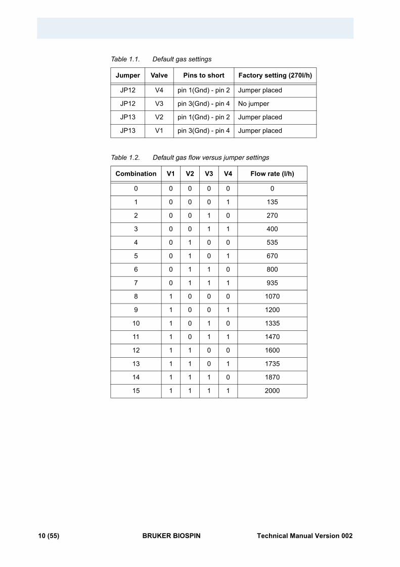
Table 1.1. Default gas settings
Table 1.2. Default gas flow versus jumper settings
Jumper Valve Pins to short Factory setting (270l/h)
JP12 V4 pin 1(Gnd) - pin 2 Jumper placed
JP12 V3 pin 3(Gnd) - pin 4 No jumper
JP13 V2 pin 1(Gnd) - pin 2 Jumper placed
JP13 V1 pin 3(Gnd) - pin 4 Jumper placed
Combination V1 V2 V3 V4 Flow rate (l/h)
0 0 0 0 0 0
1 0 0 0 1 135
2 0 0 1 0 270
3 0 0 1 1 400
4 0 1 0 0 535
5 0 1 0 1 670
6 0 1 1 0 800
7 0 1 1 1 935
8 1 0 0 0 1070
9 1 0 0 1 1200
10 1 0 1 0 1335
11 1 0 1 1 1470
12 1 1 0 0 1600
13 1 1 0 1 1735
14 1 1 1 0 1870
15 1 1 1 1 2000
10 (55) BRUKER BIOSPIN Technical Manual Version 002
Front panel connectors
Front panel connectors 1.7
Heater connector 1.7.1
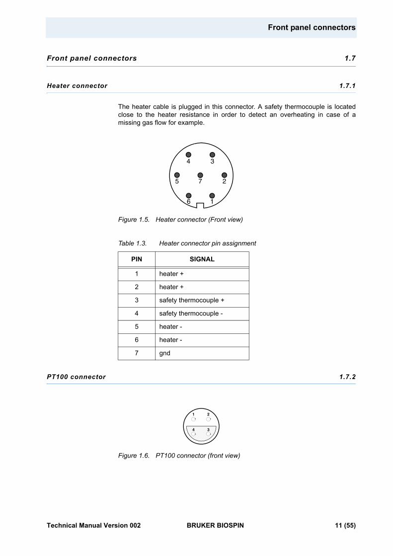
The heater cable is plugged in this connector. A safety thermocouple is located close to the heater resistance in order to detect an overheating in case of a missing gas flow for example.
Figure 1.5. Heater connector (Front view)
Table 1.3. Heater connector pin assignment
PT100 connector 1.7.2
Figure 1.6. PT100 connector (front view)
PIN SIGNAL
1 heater +
2 heater +
3 safety thermocouple +
4 safety thermocouple -
5 heater -
6 heater -
7 gnd
4 3
2
16
5 7
1
4 3
2
Technical Manual Version 002 BRUKER BIOSPIN 11 (55)
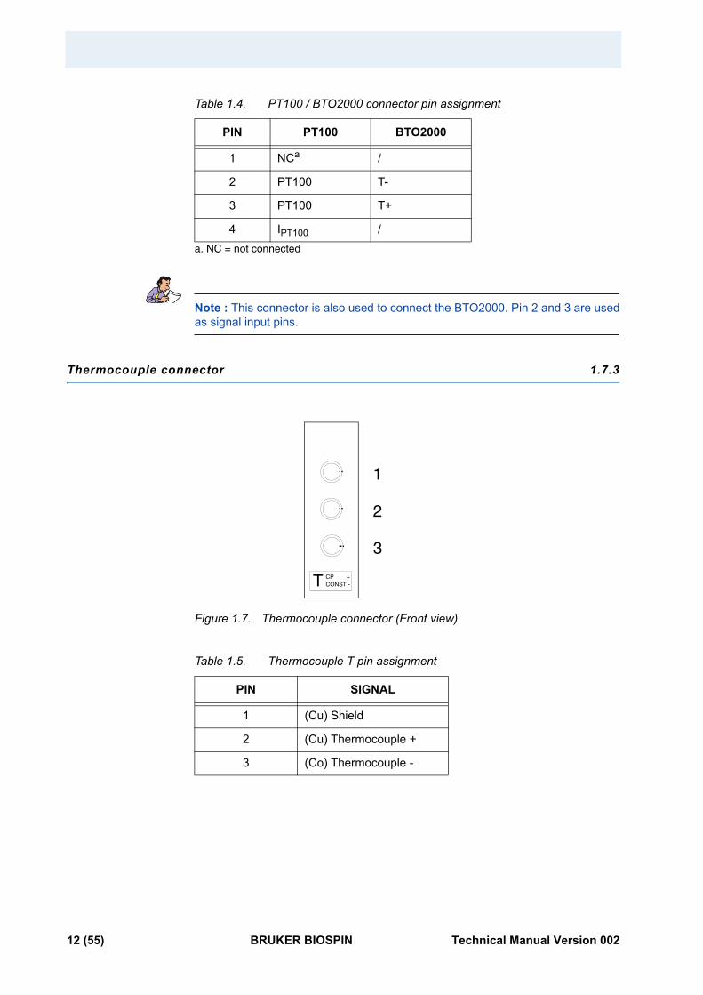
Table 1.4. PT100 / BTO2000 connector pin assignment
Note : This connector is also used to connect the BTO2000. Pin 2 and 3 are used as signal input pins.
Thermocouple connector 1.7.3
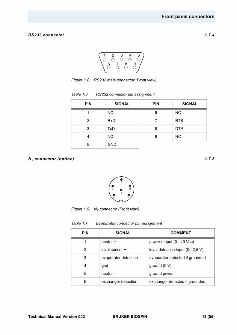
Figure 1.7. Thermocouple connector (Front view)
Table 1.5. Thermocouple T pin assignment
PIN PT100 BTO2000
1 NCa
a. NC = not connected
/
2 PT100 T-
3 PT100 T+
4 IPT100 /
PIN SIGNAL
1 (Cu) Shield
2 (Cu) Thermocouple +
3 (Co) Thermocouple -
T CPCONST -
1
2
3
+
12 (55) BRUKER BIOSPIN Technical Manual Version 002
Front panel connectors
RS232 connector 1.7.4
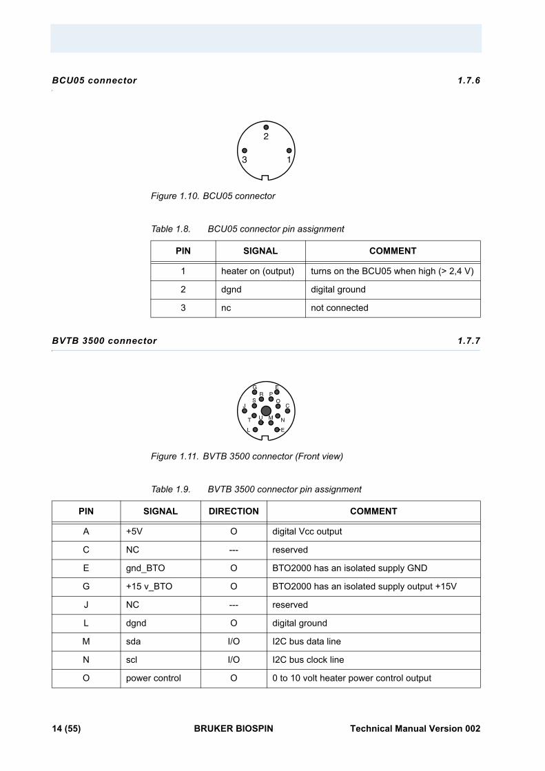
Figure 1.8. RS232 male connector (Front view)
Table 1.6. RS232 connector pin assignment
N2 connector (option) 1.7.5
Figure 1.9. N2 connector (Front view)
Table 1.7. Evaporator connector pin assignment
PIN SIGNAL PIN SIGNAL
1 NC 6 NC
2 RxD 7 RTS
3 TxD 8 DTR
4 NC 9 NC
5 GND
PIN SIGNAL COMMENT
1 heater + power output (0 - 40 Vac)
2 level sensor + level detection input (0 - 2,5 V)
3 evaporator detection evaporator detected if grounded
4 gnd ground (0 V)
5 heater - ground power
6 exchanger detection exchanger detected if grounded
1 2 3 4 5
7 986
4
3
2
1
6
5
Technical Manual Version 002 BRUKER BIOSPIN 13 (55)
BCU05 connector 1.7.6
Figure 1.10. BCU05 connector
Table 1.8. BCU05 connector pin assignment
BVTB 3500 connector 1.7.7
Figure 1.11. BVTB 3500 connector (Front view)
Table 1.9. BVTB 3500 connector pin assignment
PIN SIGNAL COMMENT
1 heater on (output) turns on the BCU05 when high (> 2,4 V)
2 dgnd digital ground
3 nc not connected
PIN SIGNAL DIRECTION COMMENT
A +5V O digital Vcc output
C NC --- reserved
E gnd_BTO O BTO2000 has an isolated supply GND
G +15 v_BTO O BTO2000 has an isolated supply output +15V
J NC --- reserved
L dgnd O digital ground
M sda I/O I2C bus data line
N scl I/O I2C bus clock line
O power control O 0 to 10 volt heater power control output
3
2
1
J
E
C
E
O
NMU
L
GPR
S
T
14 (55) BRUKER BIOSPIN Technical Manual Version 002

Front panel connectors
The BVTB3500 is a power booster for the BVT3200.
P pgnd O power ground
R pgnd O power ground
S thermocouple I safety thermocouple input
T b_relay O BVTB 3500 heater relay command
U b_connected I if grounded BVTB 3500 is detected
PIN SIGNAL DIRECTION COMMENT
Technical Manual Version 002 BRUKER BIOSPIN 15 (55)

16 (55) BRUKER BIOSPIN Technical Manual Version 002
2Options 2
Low temperature options 2.1
For sample temperature control below room temperature one must use cold gas. The BVT3200 can drive several devices for cold gas production :
• LN2 heat exchanger
• LN2 evaporator
• BCU05 gas cooler
The nitrogen level in the dewar is monitored by the VTU and the power level applied to the LN2 heater is computer controlled. For both first options, an optional printed circuit must be installed. The LN2 heater cable or the exchanger cable is plugged in the N2 connector on the front plate.
LN2 exchanger 2.2
This device allows to extend sample temperature control below room temperature. A nitrogen gas supply line is required for this device. The N2 gas is cooled while passing in a heat exchanger tube which soaks in liquid nitrogen. The cold gas is then transferred to the probe by a flexible isolated transfer line.
The gas flow is stopped (it means all four valves are closed in the BVT3200) whenever the heater power is off, avoiding sample freezing.
A printed circuit (PC) must be installed in the VT unit.
The printed circuit has the part number W1101455. It is plugged on the main printed circuit and fixed by four plastic spacers.
Temperature accuracy is unchanged.
Technical Manual Version 002 BRUKER BIOSPIN 17 (55)
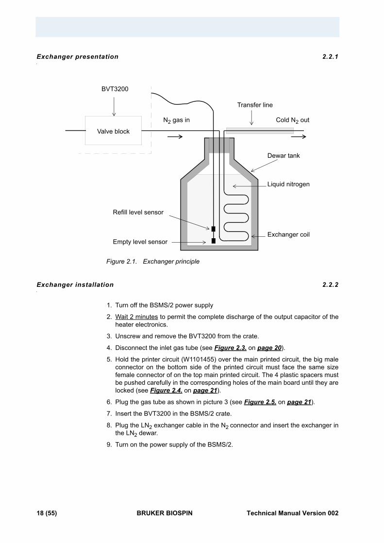
Exchanger presentation 2.2.1
Figure 2.1. Exchanger principle
Exchanger installation 2.2.2
1. Turn off the BSMS/2 power supply
2. Wait 2 minutes to permit the complete discharge of the output capacitor of the heater electronics.
3. Unscrew and remove the BVT3200 from the crate.
4. Disconnect the inlet gas tube (see Figure 2.3. on page 20).
5. Hold the printer circuit (W1101455) over the main printed circuit, the big male connector on the bottom side of the printed circuit must face the same size female connector of on the top main printed circuit. The 4 plastic spacers must be pushed carefully in the corresponding holes of the main board until they are locked (see Figure 2.4. on page 21).
6. Plug the gas tube as shown in picture 3 (see Figure 2.5. on page 21).
7. Insert the BVT3200 in the BSMS/2 crate.
8. Plug the LN2 exchanger cable in the N2 connector and insert the exchanger in the LN2 dewar.
9. Turn on the power supply of the BSMS/2.
Exchanger coil
Liquid nitrogen
Dewar tank
Refill level sensor
Empty level sensor
Valve block
Transfer line
N2 gas in Cold N2 out
BVT3200
18 (55) BRUKER BIOSPIN Technical Manual Version 002
LN2 evaporator
LN2 evaporator 2.3
This device is a cold nitrogen gas generator for low temperature experiments. The nitrogen gas is produced by evaporating the liquid nitrogen contained in a dewar. The power delivered to the heater, controlled by software, may reach 210 Watts (approx. 38 V on a 7 ohm heater). The cold gas is transferred to the probe trough a flexible and isolated transfer line.
For this device, an option printed circuit (PC) must be installed in the BVT3200. It delivers the power applied on the LN2 heater. The LN2 level in the dewar is continuously monitored by the VTU.
This PC has the part number W1101455. It is plugged on the main board of the BVT3200 and is retainded by four plastic spacers.
Temperature accuracy is unchanged.
WARNING : The BSMS/2 must be equipped with a 48V/400VA power supply (Z002840) to use the LN2 evaporator option. When a standard 48V/200VA power supply is present in the rack, the rear side must be unscrewed and removed to replace the power supply located beside the BVT3200.
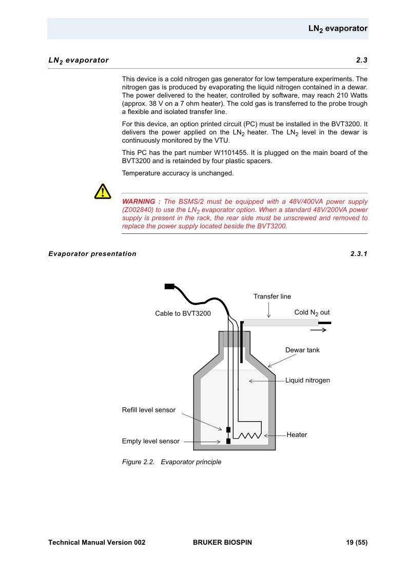
Evaporator presentation 2.3.1
Figure 2.2. Evaporator principle
Heater
Liquid nitrogen
Dewar tank
Refill level sensor
Empty level sensor
Transfer line
Cold N2 outCable to BVT3200
Technical Manual Version 002 BRUKER BIOSPIN 19 (55)
Evaporator installation 2.3.2
1. Turn off the BSMS/2 power supply.
2. Wait 2 minutes to permit the complete discharge of the output capacitor of the heater electronics.
3. Unscrew and remove the BVT3200 from the crate.
4. Disconnect the inlet gas tube (see Figure 2.3. on page 20).
5. Hold the printer circuit (W1101455) over the main printed circuit, the big male connector on the bottom side of the printed circuit must face the corresponding female connector on the component side of the main printed circuit. The 4 plastic spacers must be pushed carefully in the corresponding holes of the main board until they are locked (see Figure 2.4. on page 21).
6. Plug the gas tube as shown in picture 3 (see Figure 2.5. on page 21).
7. Insert the BVT3200 in the BSMS/2 crate.
8. Plug the LN2 evaporator cable in the connector N2 and insert the evaporator accessory in the LN2 dewar.
9. Turn on the power supply of the BSMS/2.
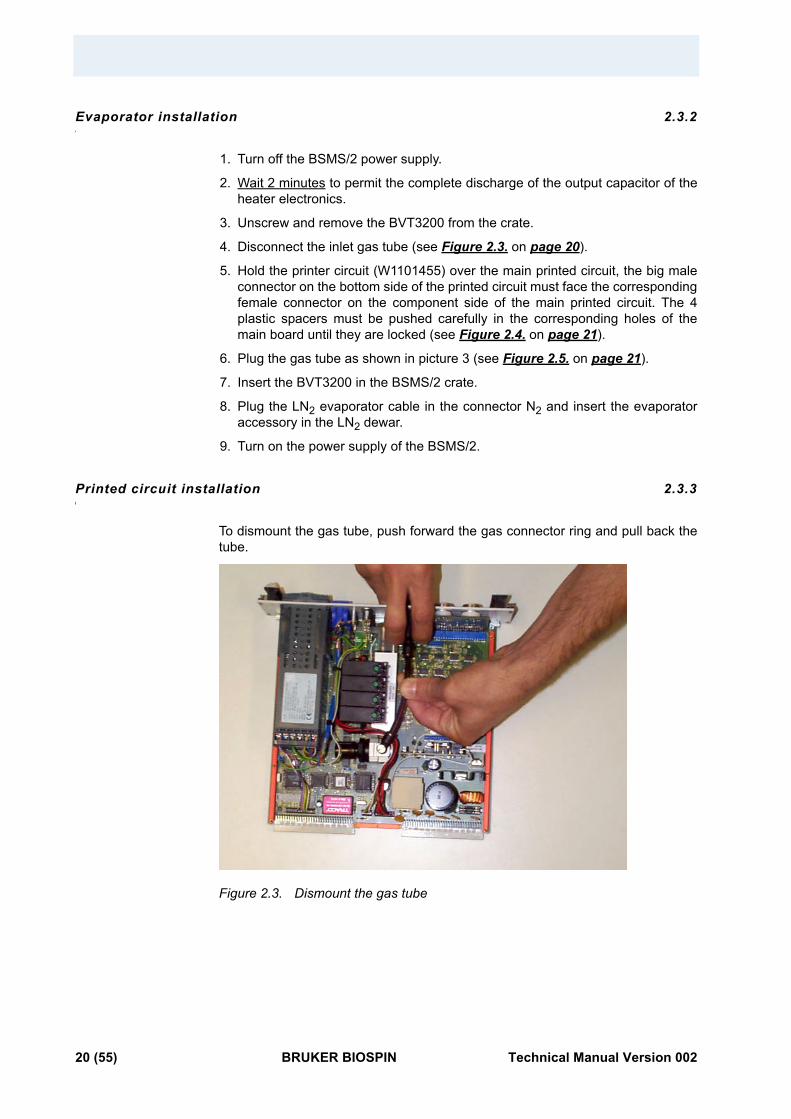
Printed circuit installation 2.3.3
To dismount the gas tube, push forward the gas connector ring and pull back the tube.
Figure 2.3. Dismount the gas tube
20 (55) BRUKER BIOSPIN Technical Manual Version 002
LN2 evaporator
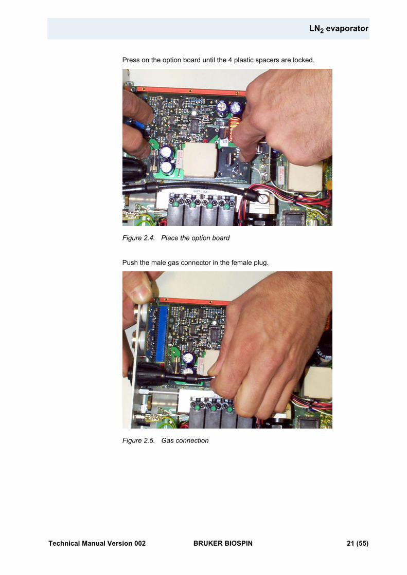
Press on the option board until the 4 plastic spacers are locked.
Figure 2.4. Place the option board
Push the male gas connector in the female plug.
Figure 2.5. Gas connection
Technical Manual Version 002 BRUKER BIOSPIN 21 (55)
BCU05 gas cooler 2.4
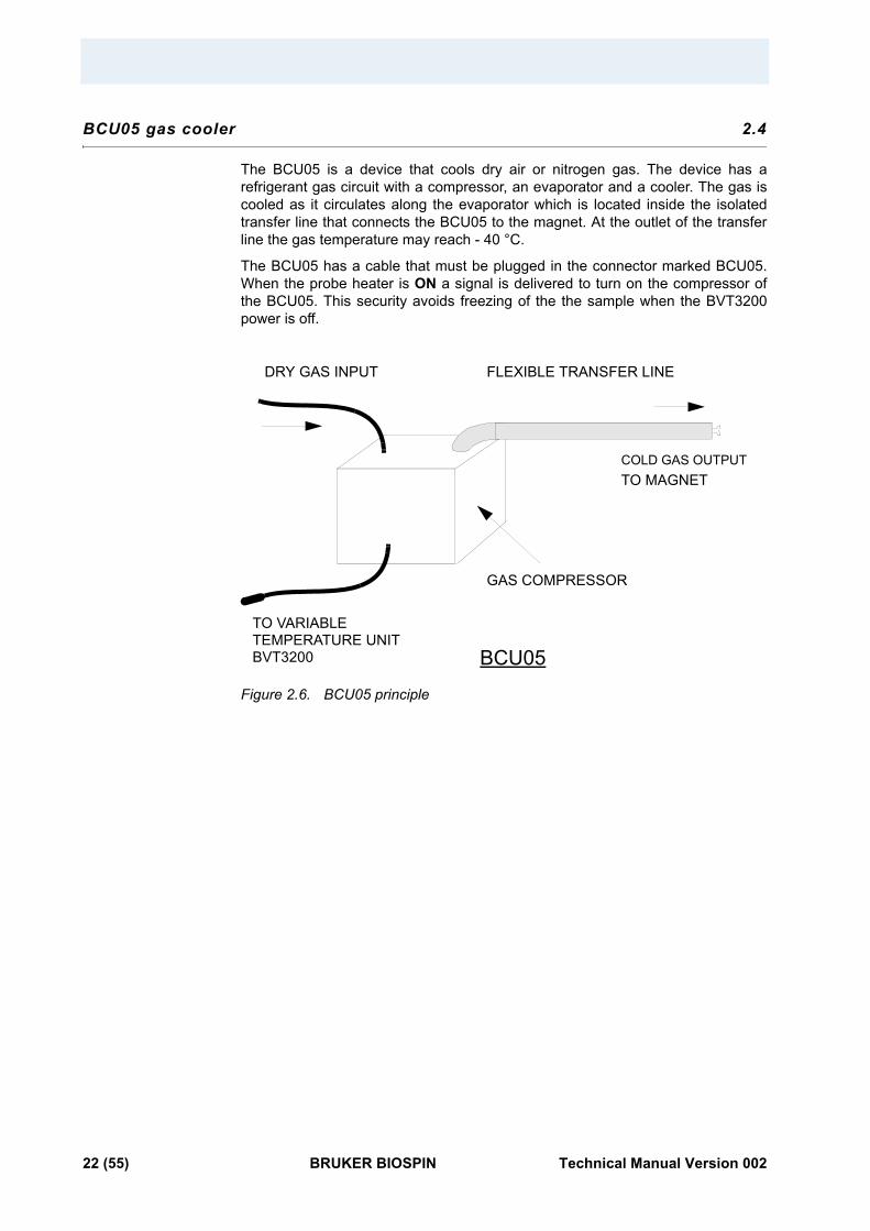
The BCU05 is a device that cools dry air or nitrogen gas. The device has a refrigerant gas circuit with a compressor, an evaporator and a cooler. The gas is cooled as it circulates along the evaporator which is located inside the isolated transfer line that connects the BCU05 to the magnet. At the outlet of the transfer line the gas temperature may reach - 40 °C.
The BCU05 has a cable that must be plugged in the connector marked BCU05. When the probe heater is ON a signal is delivered to turn on the compressor of the BCU05. This security avoids freezing of the the sample when the BVT3200power is off.
Figure 2.6. BCU05 principle
BCU05
DRY GAS INPUT FLEXIBLE TRANSFER LINE
TO MAGNET
GAS COMPRESSOR
COLD GAS OUTPUT
TO VARIABLE TEMPERATURE UNITBVT3200
22 (55) BRUKER BIOSPIN Technical Manual Version 002
3Configuration 3
Sensor selection 3.1
The BVT3200 can be used with three types of temperature sensors :
• Thermocouple T (factory set)
• BTO2000 for high stability
• PT100 sensor
Warning : Never connect two sensors at a same time on the BVT3200.
Eurotherm 2416 configuration 3.2
The Eurotherm 2416 controller must be configured to work with the right type of sensor.
The sensor can be selected in the EDTE program, it also can be chosen on the keypad of the temperature controller (see the manual of the Eurotherm 2416 controller).
Technical Manual Version 002 BRUKER BIOSPIN 23 (55)

24 (55) BRUKER BIOSPIN Technical Manual Version 002
4Remote interface control 4
Microcontroller interface 4.1
This interface has several functions :
• Host computer - Eurotherm 2416 transparent communication through a serial port.
• Transmission of BVT3200 internal status to the host computer.
• Probe heater on/off control.
• Gas flow rate settings.
• Installed option control :
1. Evaporator heating power settings.
2. Exchanger control with nitrogen level detection.
3. Etc.
Opto-isolated inputs receive informations and safety flags :
• Probe heater overheating flag.
• Gas flow detection.
• LN2 level monitoring (when option available).
• Probe heater power status flag (on/off).
• Etc.
Eight optoisolated outputs (PORT3) transmit the control byte for the DAC that delivers the LN2 heater control signal.
Digital interface specifications 4.2
Microcontroller :
8 bits 8032 microcontroller clocked at 11,05 MHz
Program Memory :
Flash EPROM 64 K. A new firmware can be downloaded in this memory through the RS232 link.
Sram :
32 Kilobytes
Eeprom :
256 bytes for manufacturing informations storage (BBIS informations).
Technical Manual Version 002 BRUKER BIOSPIN 25 (55)
Interface :
• Serial link to Eurotherm 2416 controller :
9600 bauds,1 start bit, even parity, 1 stop bit and three wires link. Baudrate can be changed by software with the «CO» command.
• Serial link to host computer :
9600 bauds,1 start bit, even parity, 1 stop bit and three wires link.
Isolation :
Optocouplers 2500V isolation between digital interface and power section.
Power supply :
V = +5 Volt, I < 1 Ampere.
Commands and communication protocol 4.3
All commands for the Eurotherm controller cross over the interface. The micro-controller looks at each received command and decides then for whom the command is intended (either for the interface itself or the Eurotherm controller). A command that is not an interface command is automatically transferred to the Eurotherm controller. If the command is processed by the Eurotherm, the controller answer is returned to the host computer via the interface.
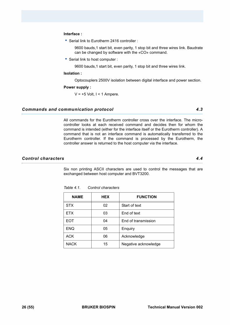
Control characters 4.4
Six non printing ASCII characters are used to control the messages that are exchanged between host computer and BVT3200.
Table 4.1. Control characters
NAME HEX FUNCTION
STX 02 Start of text
ETX 03 End of text
EOT 04 End of transmission
ENQ 05 Enquiry
ACK 06 Acknowledge
NACK 15 Negative acknowledge
26 (55) BRUKER BIOSPIN Technical Manual Version 002
List of commands
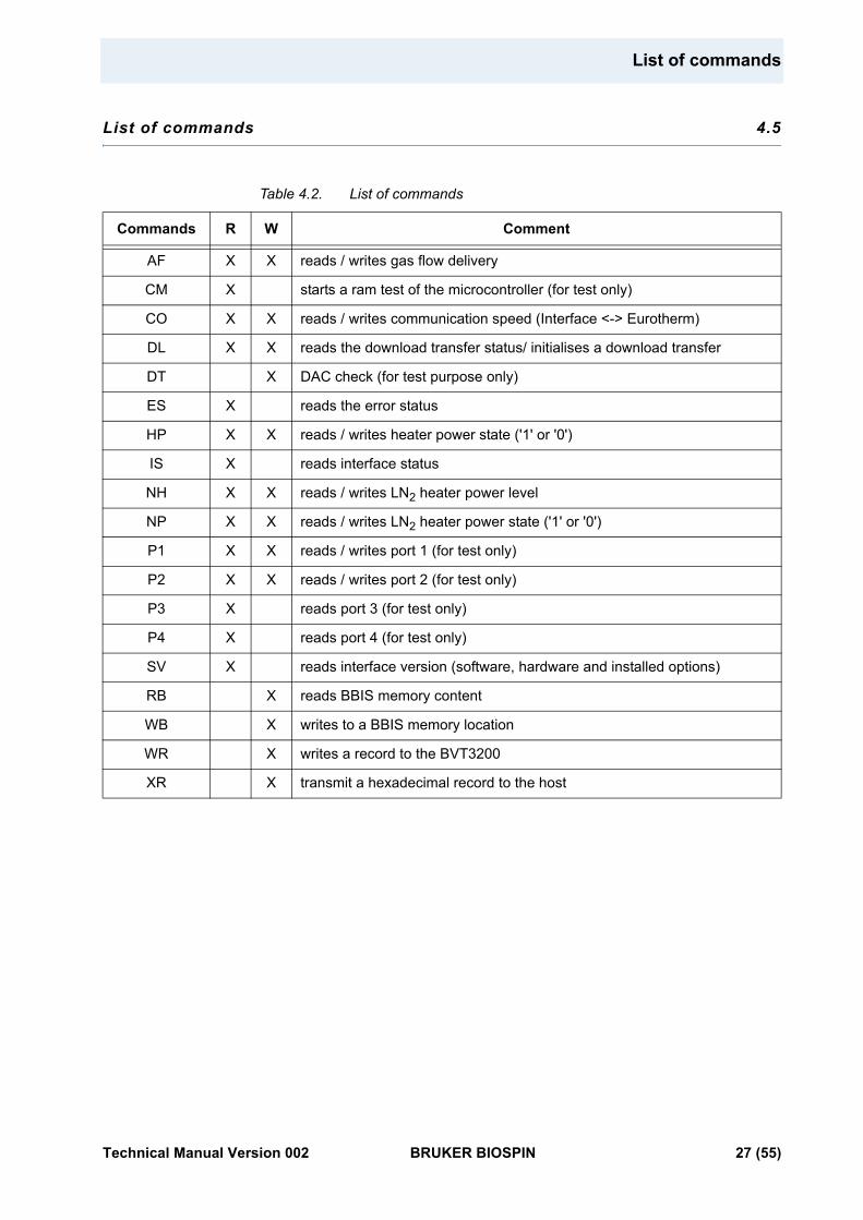
List of commands 4.5
Table 4.2. List of commands
Commands R W Comment
AF X X reads / writes gas flow delivery
CM X starts a ram test of the microcontroller (for test only)
CO X X reads / writes communication speed (Interface <-> Eurotherm)
DL X X reads the download transfer status/ initialises a download transfer
DT X DAC check (for test purpose only)
ES X reads the error status
HP X X reads / writes heater power state ('1' or '0')
IS X reads interface status
NH X X reads / writes LN2 heater power level
NP X X reads / writes LN2 heater power state ('1' or '0')
P1 X X reads / writes port 1 (for test only)
P2 X X reads / writes port 2 (for test only)
P3 X reads port 3 (for test only)
P4 X reads port 4 (for test only)
SV X reads interface version (software, hardware and installed options)
RB X reads BBIS memory content
WB X writes to a BBIS memory location
WR X writes a record to the BVT3200
XR X transmit a hexadecimal record to the host
Technical Manual Version 002 BRUKER BIOSPIN 27 (55)
RS232 link characteristics 4.6
The serial link allows a host computer to communicate with the BVT3200. It is a three wires link with no hardware or software handshake. The communication parameters are 9600 bauds, 1 start bit, even parity, 1 stop bit. RS232 connector pin assignment and names are explained above in table "RS232 connector pin assignment" on page 13.
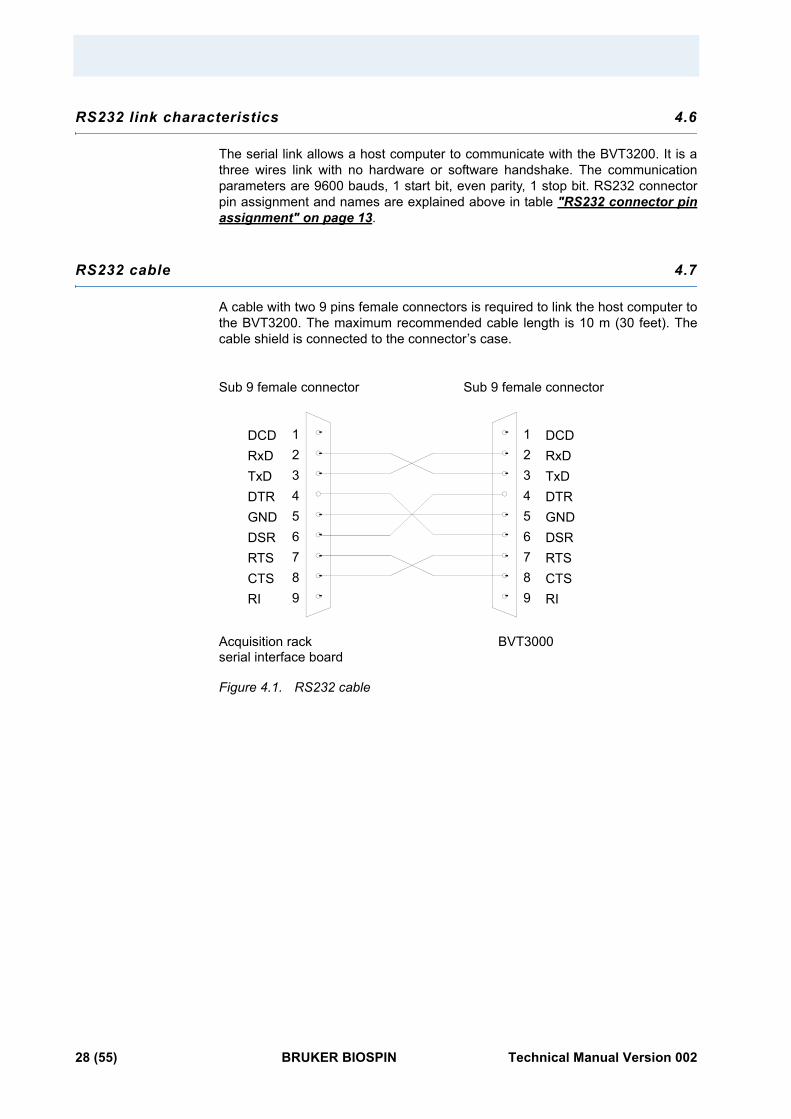
RS232 cable 4.7
A cable with two 9 pins female connectors is required to link the host computer to the BVT3200. The maximum recommended cable length is 10 m (30 feet). The cable shield is connected to the connector’s case.
Figure 4.1. RS232 cable
123456789
DCDRxDTxDDTRGNDDSRRTSCTSRI
Acquisition rackserial interface board
BVT3000
Sub 9 female connectorSub 9 female connector
123456789
DCDRxDTxDDTRGNDDSRRTSCTSRI
28 (55) BRUKER BIOSPIN Technical Manual Version 002
Authorised functions
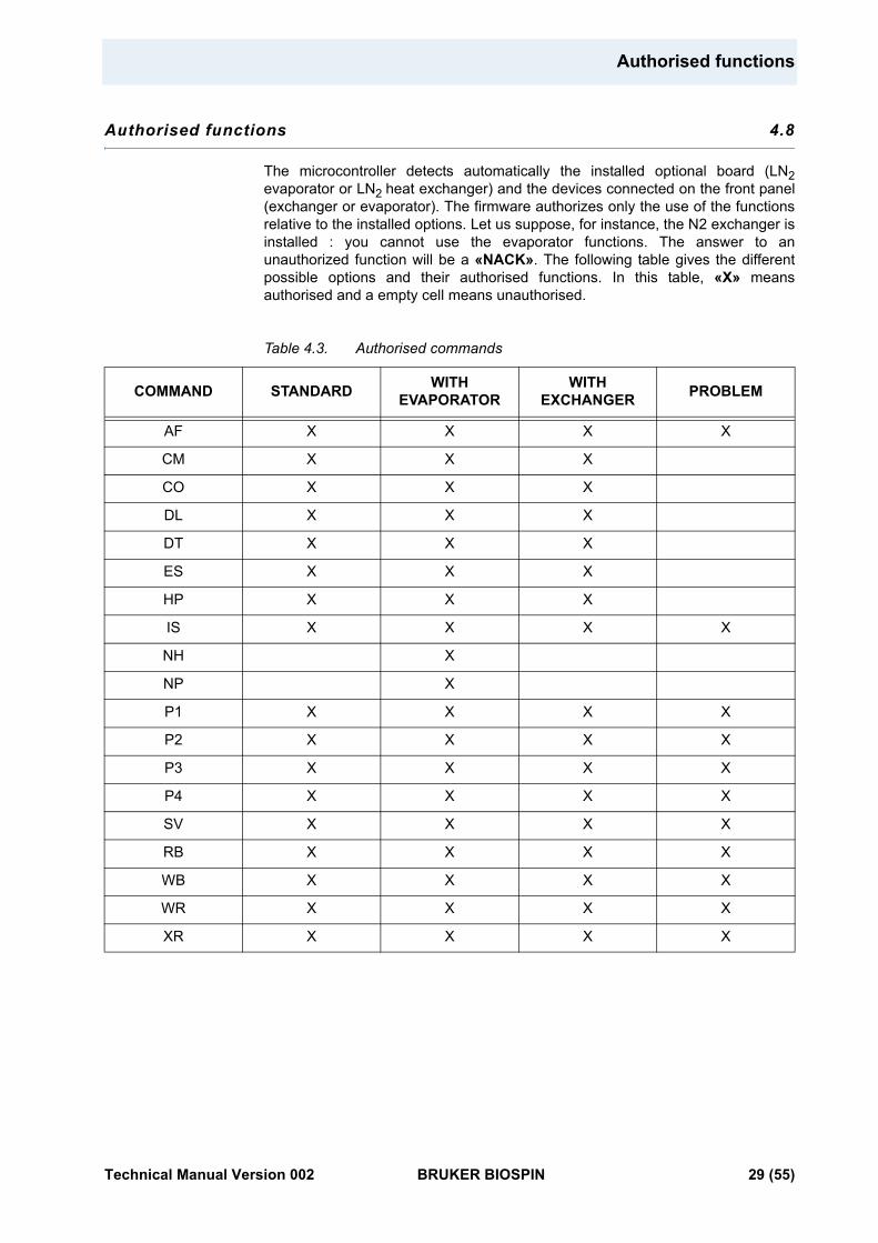
Authorised functions 4.8
The microcontroller detects automatically the installed optional board (LN2evaporator or LN2 heat exchanger) and the devices connected on the front panel (exchanger or evaporator). The firmware authorizes only the use of the functions relative to the installed options. Let us suppose, for instance, the N2 exchanger is installed : you cannot use the evaporator functions. The answer to an unauthorized function will be a «NACK». The following table gives the different possible options and their authorised functions. In this table, «X» means authorised and a empty cell means unauthorised.
Table 4.3. Authorised commands
COMMAND STANDARD WITH EVAPORATOR
WITH EXCHANGER PROBLEM
AF X X X X
CM X X X
CO X X X
DL X X X
DT X X X
ES X X X
HP X X X
IS X X X X
NH X
NP X
P1 X X X X
P2 X X X X
P3 X X X X
P4 X X X X
SV X X X X
RB X X X X
WB X X X X
WR X X X X
XR X X X X
Technical Manual Version 002 BRUKER BIOSPIN 29 (55)
AF - Air Flow 4.8.1
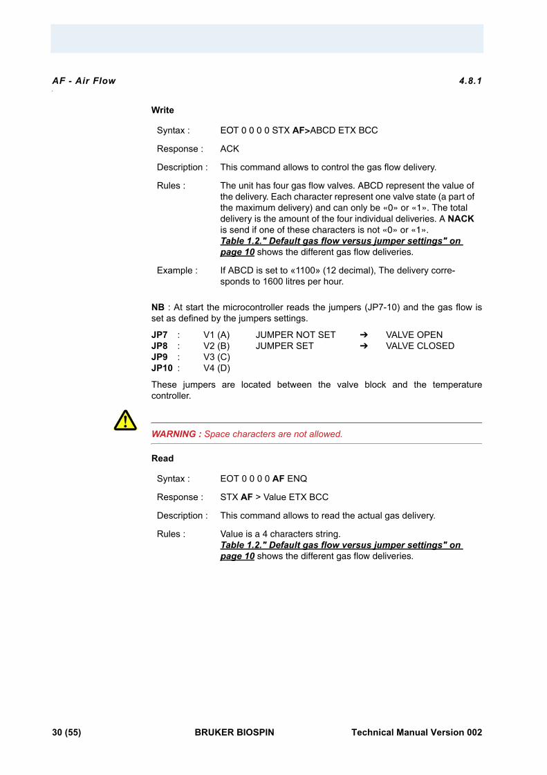
Write
NB : At start the microcontroller reads the jumpers (JP7-10) and the gas flow is set as defined by the jumpers settings.
JP7 : V1 (A) JUMPER NOT SET VALVE OPEN JP8 : V2 (B) JUMPER SET VALVE CLOSED JP9 : V3 (C) JP10 : V4 (D)
These jumpers are located between the valve block and the temperature controller.
WARNING : Space characters are not allowed.
Read
Syntax : EOT 0 0 0 0 STX AF>ABCD ETX BCC
Response : ACK
Description : This command allows to control the gas flow delivery.
Rules : The unit has four gas flow valves. ABCD represent the value of the delivery. Each character represent one valve state (a part of the maximum delivery) and can only be «0» or «1». The total delivery is the amount of the four individual deliveries. A NACK is send if one of these characters is not «0» or «1». Table 1.2." Default gas flow versus jumper settings" on page 10 shows the different gas flow deliveries.
Example : If ABCD is set to «1100» (12 decimal), The delivery corre-sponds to 1600 litres per hour.
Syntax : EOT 0 0 0 0 AF ENQ
Response : STX AF > Value ETX BCC
Description : This command allows to read the actual gas delivery.
Rules : Value is a 4 characters string. Table 1.2." Default gas flow versus jumper settings" on page 10 shows the different gas flow deliveries.
30 (55) BRUKER BIOSPIN Technical Manual Version 002
Authorised functions
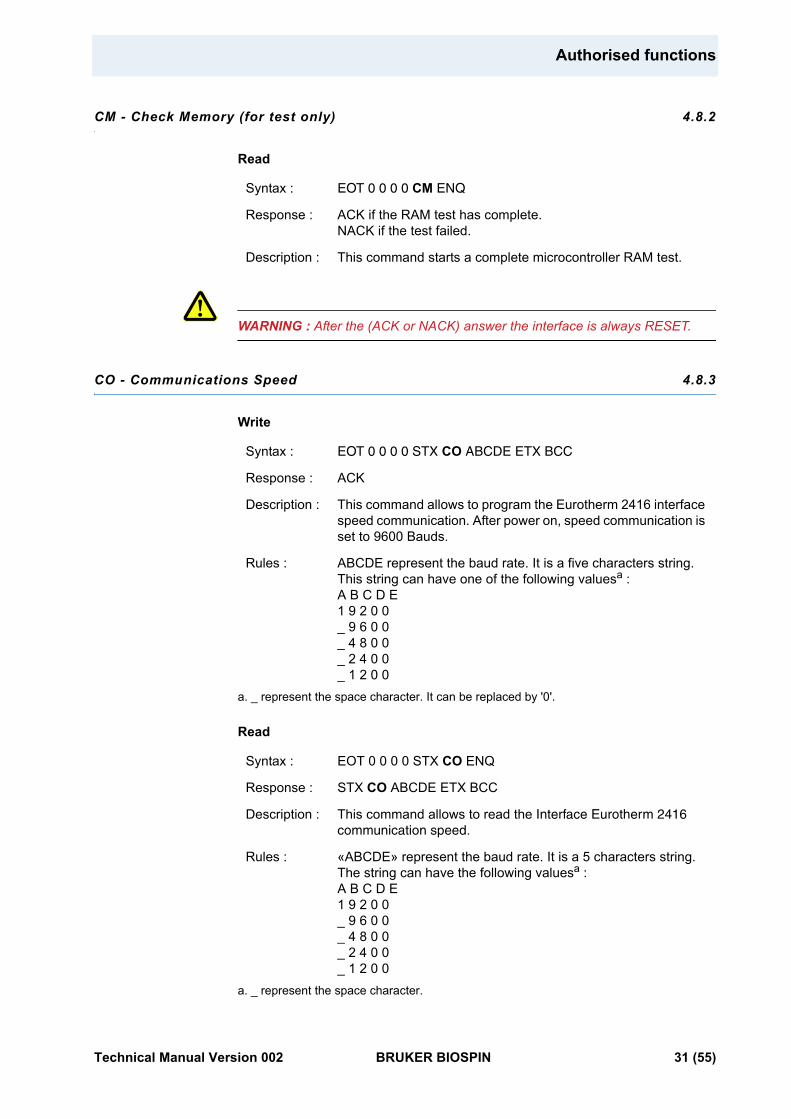
CM - Check Memory (for test only) 4.8.2
Read
WARNING : After the (ACK or NACK) answer the interface is always RESET.
CO - Communications Speed 4.8.3
Write
Read
Syntax : EOT 0 0 0 0 CM ENQ
Response : ACK if the RAM test has complete. NACK if the test failed.
Description : This command starts a complete microcontroller RAM test.
Syntax : EOT 0 0 0 0 STX CO ABCDE ETX BCC
Response : ACK
Description : This command allows to program the Eurotherm 2416 interface speed communication. After power on, speed communication is set to 9600 Bauds.
Rules : ABCDE represent the baud rate. It is a five characters string. This string can have one of the following valuesa :A B C D E1 9 2 0 0_ 9 6 0 0_ 4 8 0 0_ 2 4 0 0_ 1 2 0 0
a. _ represent the space character. It can be replaced by '0'.
Syntax : EOT 0 0 0 0 STX CO ENQ
Response : STX CO ABCDE ETX BCC
Description : This command allows to read the Interface Eurotherm 2416 communication speed.
Rules : «ABCDE» represent the baud rate. It is a 5 characters string. The string can have the following valuesa :A B C D E1 9 2 0 0_ 9 6 0 0_ 4 8 0 0_ 2 4 0 0_ 1 2 0 0
a. _ represent the space character.
Technical Manual Version 002 BRUKER BIOSPIN 31 (55)
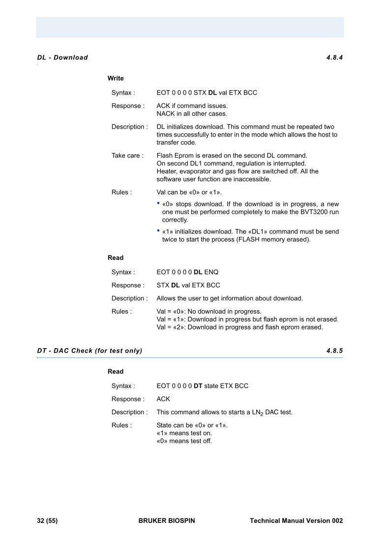
DL - Download 4.8.4
Write
Read
DT - DAC Check (for test only) 4.8.5
Read
Syntax : EOT 0 0 0 0 STX DL val ETX BCC
Response : ACK if command issues. NACK in all other cases.
Description : DL initializes download. This command must be repeated two times successfully to enter in the mode which allows the host to transfer code.
Take care : Flash Eprom is erased on the second DL command.On second DL1 command, regulation is interrupted.Heater, evaporator and gas flow are switched off. All the software user function are inaccessible.
Rules : Val can be «0» or «1».
• «0» stops download. If the download is in progress, a new one must be performed completely to make the BVT3200 run correctly.
• «1» initializes download. The «DL1» command must be send twice to start the process (FLASH memory erased).
Syntax : EOT 0 0 0 0 DL ENQ
Response : STX DL val ETX BCC
Description : Allows the user to get information about download.
Rules : Val = «0»: No download in progress.Val = «1»: Download in progress but flash eprom is not erased.Val = «2»: Download in progress and flash eprom erased.
Syntax : EOT 0 0 0 0 DT state ETX BCC
Response : ACK
Description : This command allows to starts a LN2 DAC test.
Rules : State can be «0» or «1».«1» means test on.«0» means test off.
32 (55) BRUKER BIOSPIN Technical Manual Version 002
Authorised functions
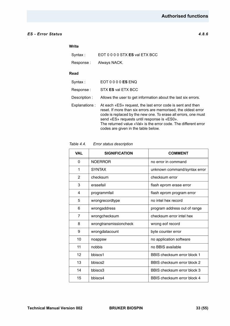
ES - Error Status 4.8.6
Write
Read
Table 4.4. Error status description
Syntax : EOT 0 0 0 0 STX ES val ETX BCC
Response : Always NACK.
Syntax : EOT 0 0 0 0 ES ENQ
Response : STX ES val ETX BCC
Description : Allows the user to get information about the last six errors.
Explanations : At each «ES» request, the last error code is sent and then reset. If more than six errors are memorised, the oldest error code is replaced by the new one. To erase all errors, one must send «ES» requests until response is «ES0».The returned value «Val» is the error code. The different error codes are given in the table below.
VAL SIGNIFICATION COMMENT
0 NOERROR no error in command
1 SYNTAX unknown command/syntax error
2 checksum checksum error
3 erasefail flash eprom erase error
4 programmfail flash eprom program error
5 wrongrecordtype no intel hex record
6 wrongaddress program address out of range
7 wrongchecksum checksum error intel hex
8 wrongtransmissioncheck wrong eof record
9 wrongdatacount byte counter error
10 noappsw no application software
11 nobbis no BBIS available
12 bbiscs1 BBIS checksum error block 1
13 bbiscs2 BBIS checksum error block 2
14 bbiscs3 BBIS checksum error block 3
15 bbiscs4 BBIS checksum error block 4
Technical Manual Version 002 BRUKER BIOSPIN 33 (55)
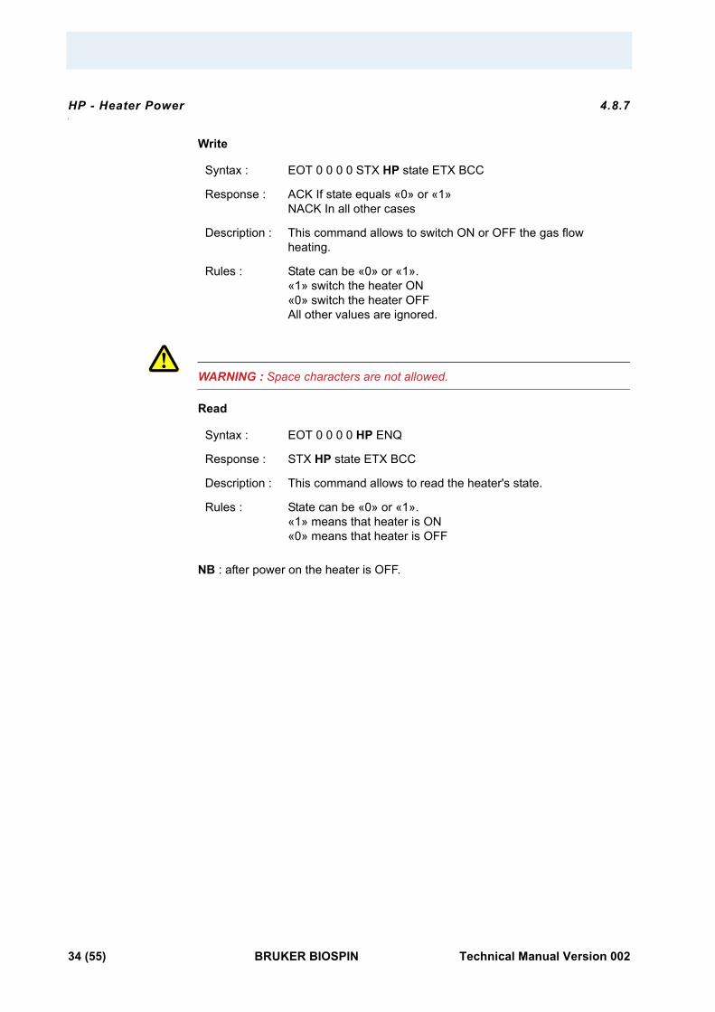
HP - Heater Power 4.8.7
Write
WARNING : Space characters are not allowed.
Read
NB : after power on the heater is OFF.
Syntax : EOT 0 0 0 0 STX HP state ETX BCC
Response : ACK If state equals «0» or «1»NACK In all other cases
Description : This command allows to switch ON or OFF the gas flow heating.
Rules : State can be «0» or «1».«1» switch the heater ON«0» switch the heater OFFAll other values are ignored.
Syntax : EOT 0 0 0 0 HP ENQ
Response : STX HP state ETX BCC
Description : This command allows to read the heater's state.
Rules : State can be «0» or «1».«1» means that heater is ON«0» means that heater is OFF
34 (55) BRUKER BIOSPIN Technical Manual Version 002
Authorised functions
IS - Interface Status 4.8.8
Read
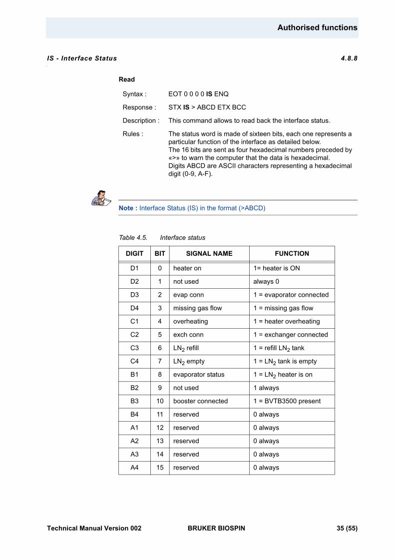
Note : Interface Status (IS) in the format (>ABCD)
Table 4.5. Interface status
Syntax : EOT 0 0 0 0 IS ENQ
Response : STX IS > ABCD ETX BCC
Description : This command allows to read back the interface status.
Rules : The status word is made of sixteen bits, each one represents a particular function of the interface as detailed below.The 16 bits are sent as four hexadecimal numbers preceded by «>» to warn the computer that the data is hexadecimal.Digits ABCD are ASCII characters representing a hexadecimal digit (0-9, A-F).
DIGIT BIT SIGNAL NAME FUNCTION
D1 0 heater on 1= heater is ON
D2 1 not used always 0
D3 2 evap conn 1 = evaporator connected
D4 3 missing gas flow 1 = missing gas flow
C1 4 overheating 1 = heater overheating
C2 5 exch conn 1 = exchanger connected
C3 6 LN2 refill 1 = refill LN2 tank
C4 7 LN2 empty 1 = LN2 tank is empty
B1 8 evaporator status 1 = LN2 heater is on
B2 9 not used 1 always
B3 10 booster connected 1 = BVTB3500 present
B4 11 reserved 0 always
A1 12 reserved 0 always
A2 13 reserved 0 always
A3 14 reserved 0 always
A4 15 reserved 0 always
Technical Manual Version 002 BRUKER BIOSPIN 35 (55)
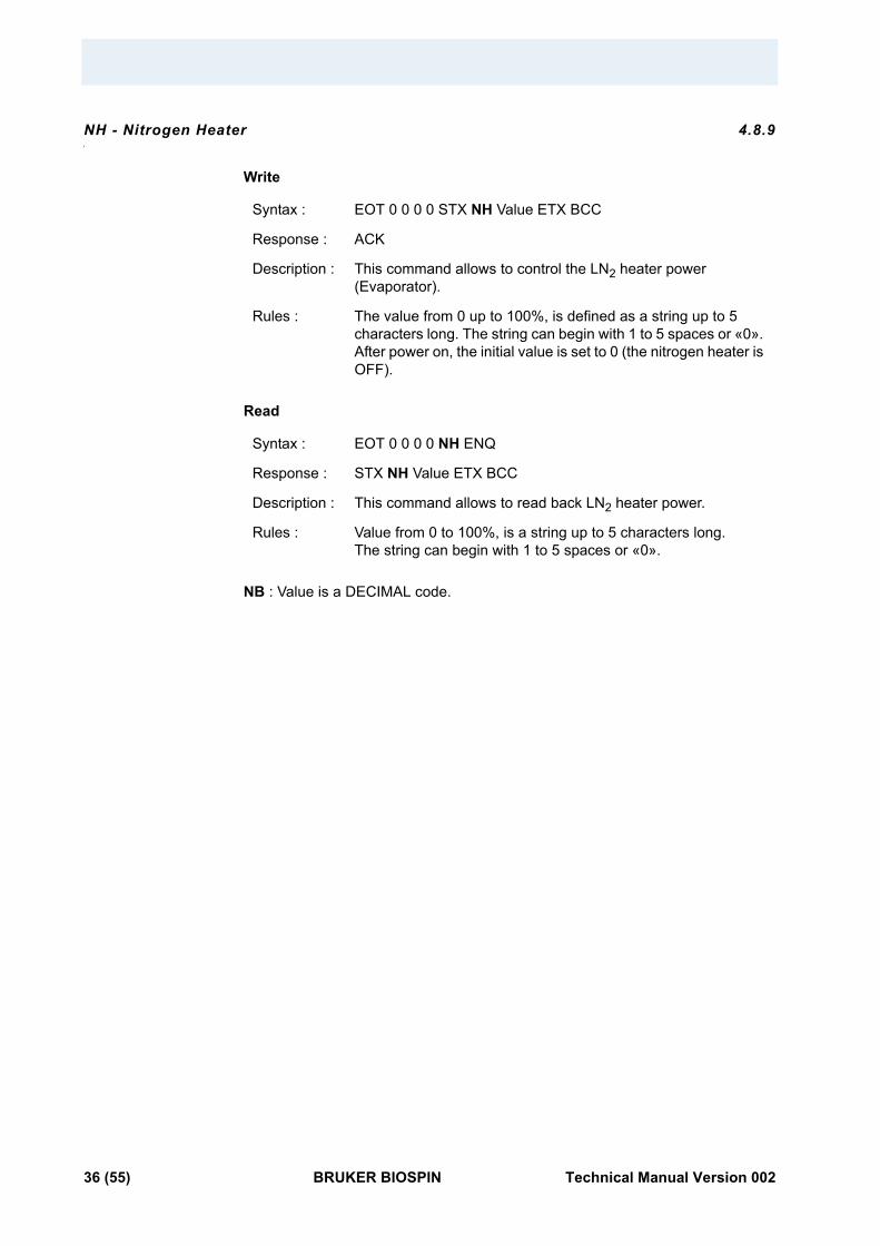
NH - Nitrogen Heater 4.8.9
Write
Read
NB : Value is a DECIMAL code.
Syntax : EOT 0 0 0 0 STX NH Value ETX BCC
Response : ACK
Description : This command allows to control the LN2 heater power (Evaporator).
Rules : The value from 0 up to 100%, is defined as a string up to 5 characters long. The string can begin with 1 to 5 spaces or «0». After power on, the initial value is set to 0 (the nitrogen heater is OFF).
Syntax : EOT 0 0 0 0 NH ENQ
Response : STX NH Value ETX BCC
Description : This command allows to read back LN2 heater power.
Rules : Value from 0 to 100%, is a string up to 5 characters long.The string can begin with 1 to 5 spaces or «0».
36 (55) BRUKER BIOSPIN Technical Manual Version 002
Authorised functions
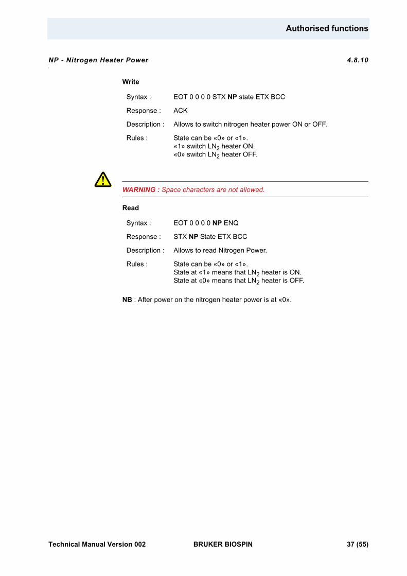
NP - Nitrogen Heater Power 4.8.10
Write
WARNING : Space characters are not allowed.
Read
NB : After power on the nitrogen heater power is at «0».
Syntax : EOT 0 0 0 0 STX NP state ETX BCC
Response : ACK
Description : Allows to switch nitrogen heater power ON or OFF.
Rules : State can be «0» or «1».«1» switch LN2 heater ON.«0» switch LN2 heater OFF.
Syntax : EOT 0 0 0 0 NP ENQ
Response : STX NP State ETX BCC
Description : Allows to read Nitrogen Power.
Rules : State can be «0» or «1». State at «1» means that LN2 heater is ON.State at «0» means that LN2 heater is OFF.
Technical Manual Version 002 BRUKER BIOSPIN 37 (55)
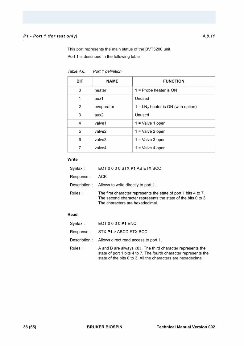
P1 - Port 1 (for test only) 4.8.11
This port represents the main status of the BVT3200 unit.
Port 1 is described in the following table
Table 4.6. Port 1 definition
Write
Read
BIT NAME FUNCTION
0 heater 1 = Probe heater is ON
1 aux1 Unused
2 evaporator 1 = LN2 heater is ON (with option)
3 aux2 Unused
4 valve1 1 = Valve 1 open
5 valve2 1 = Valve 2 open
6 valve3 1 = Valve 3 open
7 valve4 1 = Valve 4 open
Syntax : EOT 0 0 0 0 STX P1 AB ETX BCC
Response : ACK
Description : Allows to write directly to port 1.
Rules : The first character represents the state of port 1 bits 4 to 7. The second character represents the state of the bits 0 to 3. The characters are hexadecimal.
Syntax : EOT 0 0 0 0 P1 ENQ
Response : STX P1 > ABCD ETX BCC
Description : Allows direct read access to port 1.
Rules : A and B are always «0». The third character represents the state of port 1 bits 4 to 7. The fourth character represents the state of the bits 0 to 3. All the characters are hexadecimal.
38 (55) BRUKER BIOSPIN Technical Manual Version 002
Authorised functions
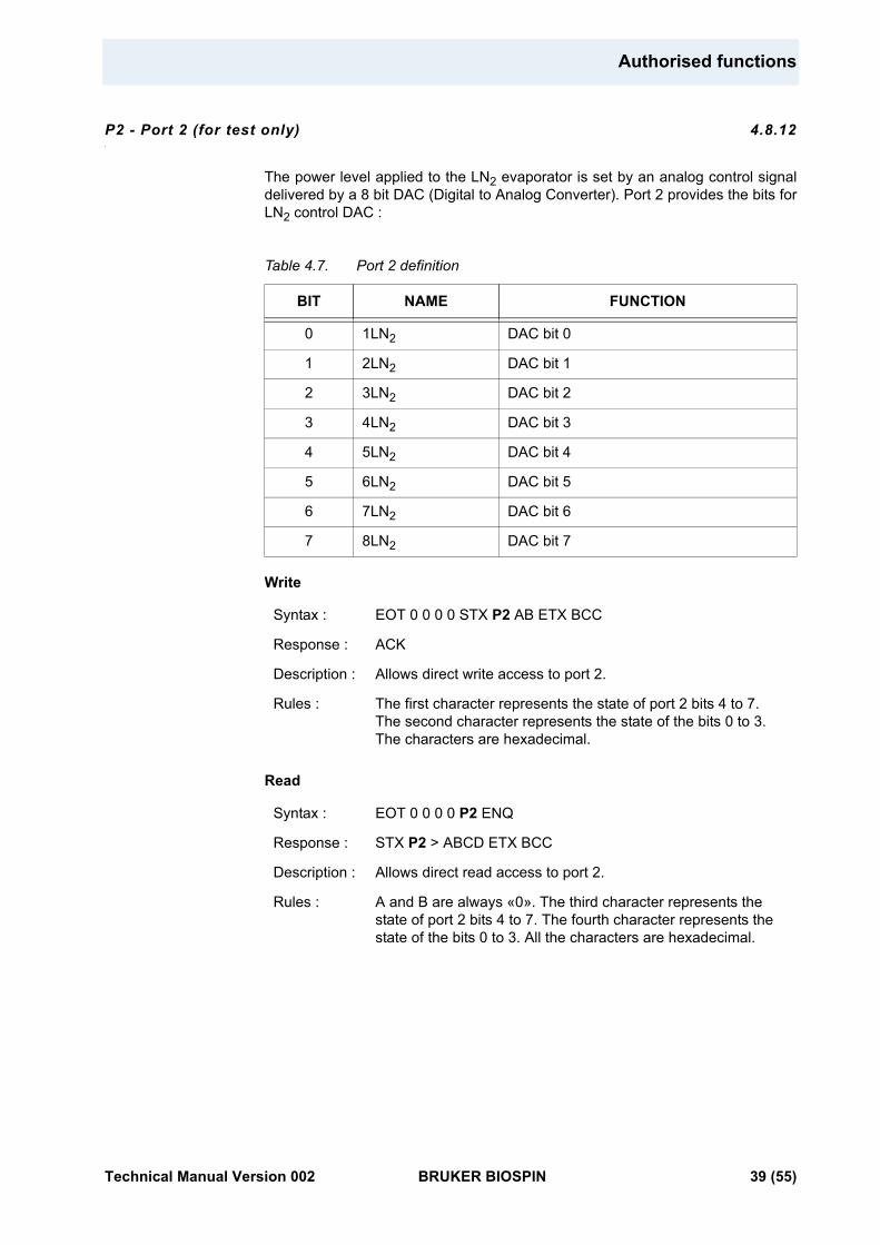
P2 - Port 2 (for test only) 4.8.12
The power level applied to the LN2 evaporator is set by an analog control signal delivered by a 8 bit DAC (Digital to Analog Converter). Port 2 provides the bits for LN2 control DAC :
Table 4.7. Port 2 definition
Write
Read
BIT NAME FUNCTION
0 1LN2 DAC bit 0
1 2LN2 DAC bit 1
2 3LN2 DAC bit 2
3 4LN2 DAC bit 3
4 5LN2 DAC bit 4
5 6LN2 DAC bit 5
6 7LN2 DAC bit 6
7 8LN2 DAC bit 7
Syntax : EOT 0 0 0 0 STX P2 AB ETX BCC
Response : ACK
Description : Allows direct write access to port 2.
Rules : The first character represents the state of port 2 bits 4 to 7. The second character represents the state of the bits 0 to 3. The characters are hexadecimal.
Syntax : EOT 0 0 0 0 P2 ENQ
Response : STX P2 > ABCD ETX BCC
Description : Allows direct read access to port 2.
Rules : A and B are always «0». The third character represents the state of port 2 bits 4 to 7. The fourth character represents the state of the bits 0 to 3. All the characters are hexadecimal.
Technical Manual Version 002 BRUKER BIOSPIN 39 (55)
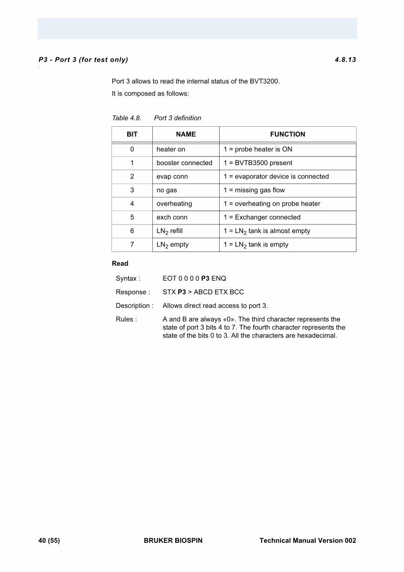
P3 - Port 3 (for test only) 4.8.13
Port 3 allows to read the internal status of the BVT3200.
It is composed as follows:
Table 4.8. Port 3 definition
Read
BIT NAME FUNCTION
0 heater on 1 = probe heater is ON
1 booster connected 1 = BVTB3500 present
2 evap conn 1 = evaporator device is connected
3 no gas 1 = missing gas flow
4 overheating 1 = overheating on probe heater
5 exch conn 1 = Exchanger connected
6 LN2 refill 1 = LN2 tank is almost empty
7 LN2 empty 1 = LN2 tank is empty
Syntax : EOT 0 0 0 0 P3 ENQ
Response : STX P3 > ABCD ETX BCC
Description : Allows direct read access to port 3.
Rules : A and B are always «0». The third character represents the state of port 3 bits 4 to 7. The fourth character represents the state of the bits 0 to 3. All the characters are hexadecimal.
40 (55) BRUKER BIOSPIN Technical Manual Version 002
Authorised functions
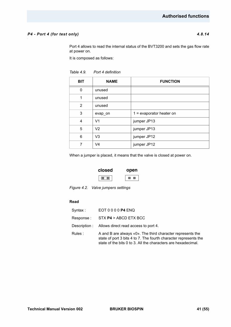
P4 - Port 4 (for test only) 4.8.14
Port 4 allows to read the internal status of the BVT3200 and sets the gas flow rate at power on.
It is composed as follows:
Table 4.9. Port 4 definition
When a jumper is placed, it means that the valve is closed at power on.
Figure 4.2. Valve jumpers settings
Read
BIT NAME FUNCTION
0 unused
1 unused
2 unused
3 evap_on 1 = evaporator heater on
4 V1 jumper JP13
5 V2 jumper JP13
6 V3 jumper JP12
7 V4 jumper JP12
Syntax : EOT 0 0 0 0 P4 ENQ
Response : STX P4 > ABCD ETX BCC
Description : Allows direct read access to port 4.
Rules : A and B are always «0». The third character represents the state of port 3 bits 4 to 7. The fourth character represents the state of the bits 0 to 3. All the characters are hexadecimal.
closed open
Technical Manual Version 002 BRUKER BIOSPIN 41 (55)
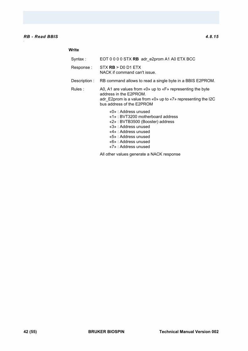
RB - Read BBIS 4.8.15
Write
Syntax : EOT 0 0 0 0 STX RB adr_e2prom A1 A0 ETX BCC
Response : STX RB > D0 D1 ETXNACK if command can't issue.
Description : RB command allows to read a single byte in a BBIS E2PROM.
Rules : A0, A1 are values from «0» up to «F» representing the byte address in the E2PROM.adr_E2prom is a value from «0» up to «7» representing the I2C bus address of the E2PROM
«0» : Address unused «1» : BVT3200 motherboard address «2» : BVTB3500 (Booster) address «3» : Address unused «4» : Address unused «5» : Address unused «6» : Address unused «7» : Address unused
All other values generate a NACK response
42 (55) BRUKER BIOSPIN Technical Manual Version 002
Authorised functions
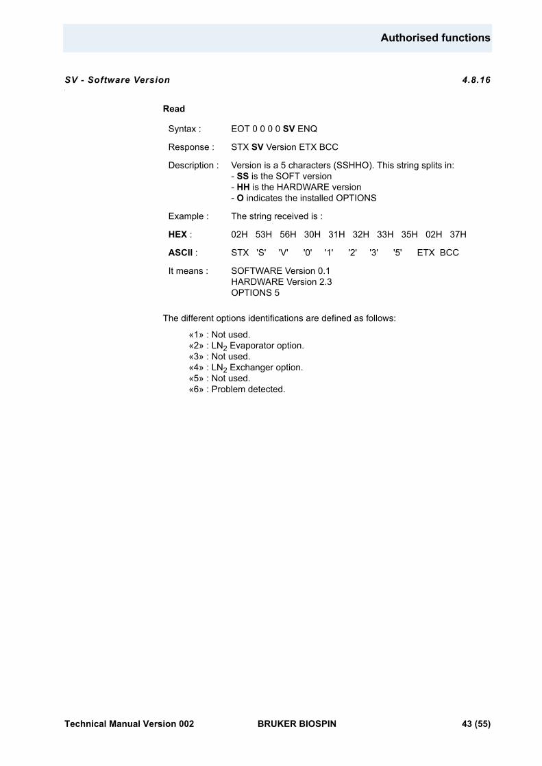
SV - Software Version 4.8.16
Read
The different options identifications are defined as follows:
«1» : Not used. «2» : LN2 Evaporator option. «3» : Not used. «4» : LN2 Exchanger option. «5» : Not used. «6» : Problem detected.
Syntax : EOT 0 0 0 0 SV ENQ
Response : STX SV Version ETX BCC
Description : Version is a 5 characters (SSHHO). This string splits in:- SS is the SOFT version- HH is the HARDWARE version- O indicates the installed OPTIONS
Example : The string received is :
HEX : 02H 53H 56H 30H 31H 32H 33H 35H 02H 37H
ASCII : STX 'S' 'V' '0' '1' '2' '3' '5' ETX BCC
It means : SOFTWARE Version 0.1HARDWARE Version 2.3OPTIONS 5
Technical Manual Version 002 BRUKER BIOSPIN 43 (55)
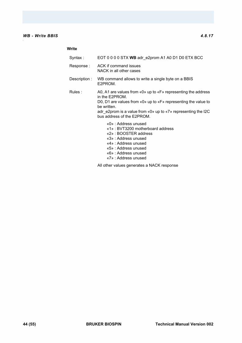
WB - Write BBIS 4.8.17
Write
Syntax : EOT 0 0 0 0 STX WB adr_e2prom A1 A0 D1 D0 ETX BCC
Response : ACK if command issuesNACK in all other cases
Description : WB command allows to write a single byte on a BBIS E2PROM.
Rules : A0, A1 are values from «0» up to «F» representing the address in the E2PROM.D0, D1 are values from «0» up to «F» representing the value to be written.adr_e2prom is a value from «0» up to «7» representing the I2C bus address of the E2PROM.
«0» : Address unused «1» : BVT3200 motherboard address «2» : BOOSTER address «3» : Address unused «4» : Address unused «5» : Address unused «6» : Address unused «7» : Address unused
All other values generates a NACK response
44 (55) BRUKER BIOSPIN Technical Manual Version 002
Authorised functions
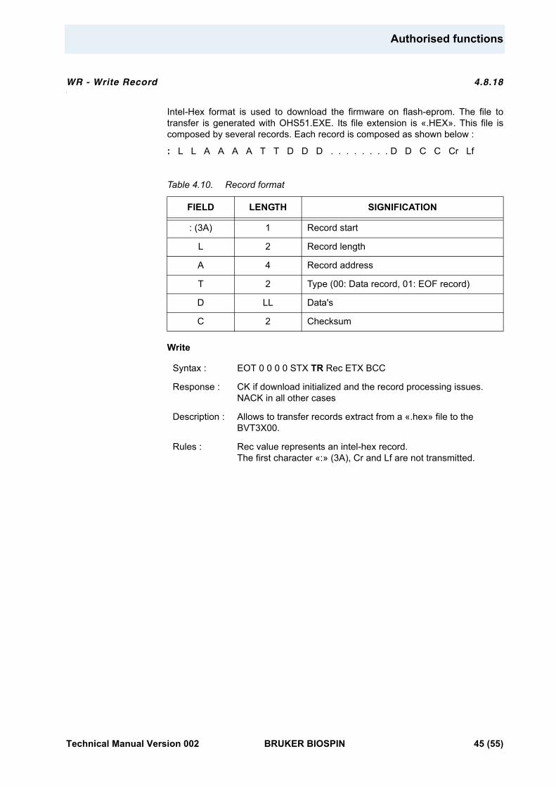
WR - Write Record 4.8.18
Intel-Hex format is used to download the firmware on flash-eprom. The file to transfer is generated with OHS51.EXE. Its file extension is «.HEX». This file is composed by several records. Each record is composed as shown below :
: L L A A A A T T D D D . . . . . . . . D D C C Cr Lf
Table 4.10. Record format
Write
FIELD LENGTH SIGNIFICATION
: (3A) 1 Record start
L 2 Record length
A 4 Record address
T 2 Type (00: Data record, 01: EOF record)
D LL Data's
C 2 Checksum
Syntax : EOT 0 0 0 0 STX TR Rec ETX BCC
Response : CK if download initialized and the record processing issues.NACK in all other cases
Description : Allows to transfer records extract from a «.hex» file to the BVT3X00.
Rules : Rec value represents an intel-hex record.The first character «:» (3A), Cr and Lf are not transmitted.
Technical Manual Version 002 BRUKER BIOSPIN 45 (55)
XR (Extract a record) 4.8.19
Write
The upload process is initialized by receiving «XR1» from the host computer. The BVT3200 sends the first Intel-hex record. The BVT3200 waits then for «XR2» to continue.
This command autorizes the BVT3200 to send the next record. This handshake continues until the BVT3200 sends the last record which is «0 0 0 0 0 0 0 1 F F». Host computer must detect it. Then, BVT3200 sends an «XR0» requests to terminate upload process and return to normal mode.
If BVT3200 receives an «XR3» command, the previous record is sent again.
An «XR0» Command must be sent to terminate the upload sequence and return to normal mode.
Syntax : EOT 0 0 0 0 STX XR Val ETX BCC
Response : STX 0 0 0 0 XR Rec BCC
Description : This command is useful to save a working software before to process a new download.
Take care : If Val = 1, regulation is interrupted. Heater, evaporator and gas flow are switched off.All the software user function are inaccessible.
Rules : Val = 0 : Stops the upload process.Val = 1 : Initilizes the upload process.Val = 2 : Autorizes the BVT3200 to send the next record.Val = 3 : Ask the BVT3200 to send the same record again.
46 (55) BRUKER BIOSPIN Technical Manual Version 002
5Technical specifications 5
Specifications 5.1
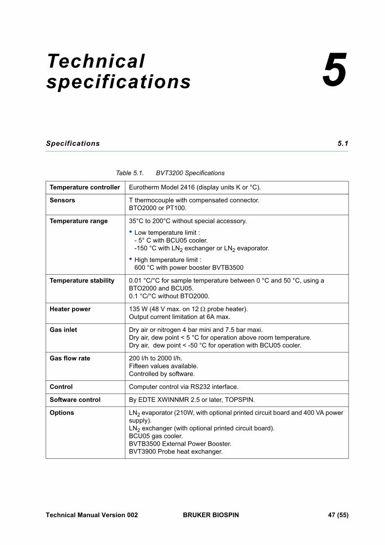
Table 5.1. BVT3200 Specifications
Temperature controller Eurotherm Model 2416 (display units K or °C).
Sensors T thermocouple with compensated connector.BTO2000 or PT100.
Temperature range 35°C to 200°C without special accessory.
• Low temperature limit : - 5° C with BCU05 cooler. -150 °C with LN2 exchanger or LN2 evaporator.
• High temperature limit : 600 °C with power booster BVTB3500
Temperature stability 0.01 °C/°C for sample temperature between 0 °C and 50 °C, using a BTO2000 and BCU05.0.1 °C/°C without BTO2000.
Heater power 135 W (48 V max. on 12 Ω probe heater).Output current limitation at 6A max.
Gas inlet Dry air or nitrogen 4 bar mini and 7.5 bar maxi.Dry air, dew point < 5 °C for operation above room temperature.Dry air, dew point < -50 °C for operation with BCU05 cooler.
Gas flow rate 200 l/h to 2000 l/h.Fifteen values available.Controlled by software.
Control Computer control via RS232 interface.
Software control By EDTE XWINNMR 2.5 or later, TOPSPIN.
Options LN2 evaporator (210W, with optional printed circuit board and 400 VA power supply).LN2 exchanger (with optional printed circuit board).BCU05 gas cooler.BVTB3500 External Power Booster.BVT3900 Probe heat exchanger.
Technical Manual Version 002 BRUKER BIOSPIN 47 (55)
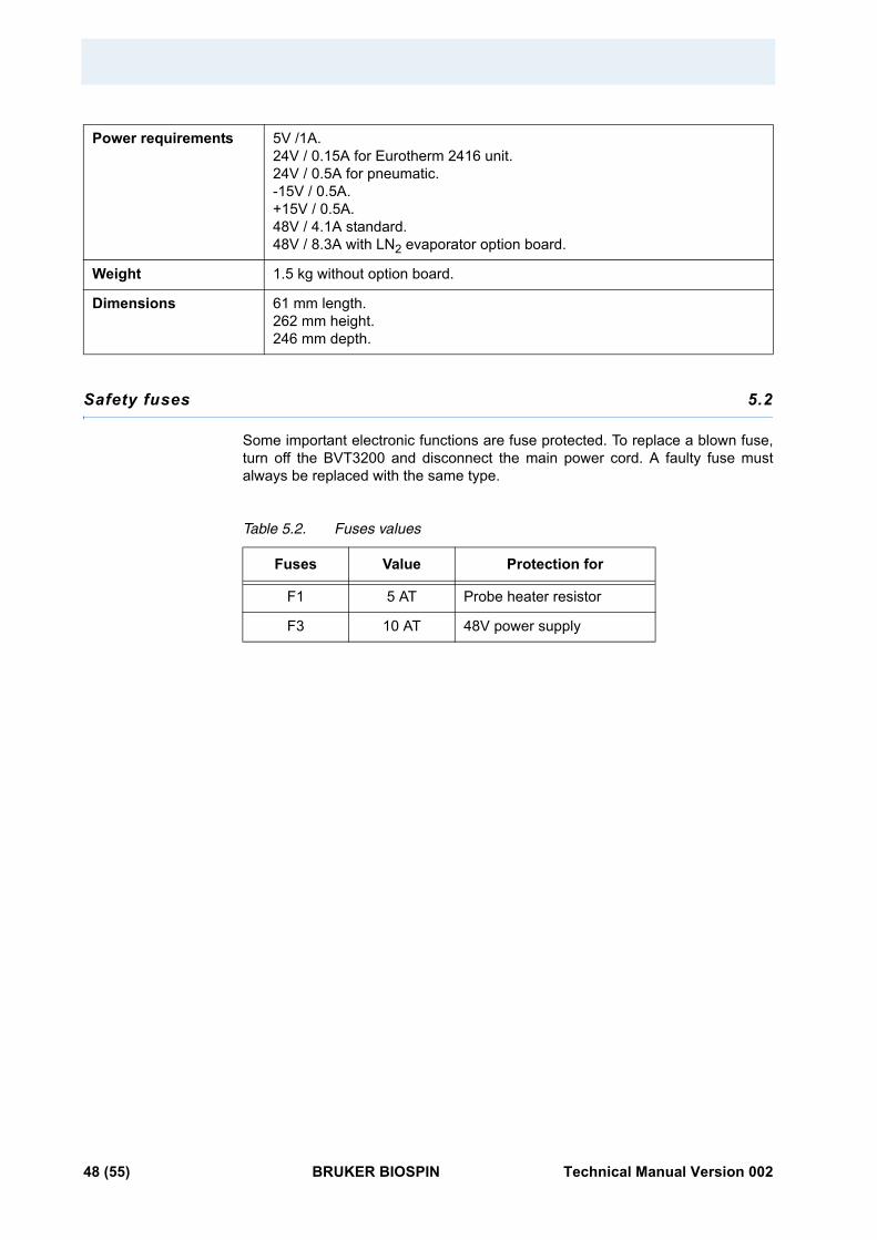
Safety fuses 5.2
Some important electronic functions are fuse protected. To replace a blown fuse, turn off the BVT3200 and disconnect the main power cord. A faulty fuse must always be replaced with the same type.
Table 5.2. Fuses values
Power requirements 5V /1A.24V / 0.15A for Eurotherm 2416 unit.24V / 0.5A for pneumatic.-15V / 0.5A.+15V / 0.5A.48V / 4.1A standard.48V / 8.3A with LN2 evaporator option board.
Weight 1.5 kg without option board.
Dimensions 61 mm length.262 mm height.246 mm depth.
Fuses Value Protection for
F1 5 AT Probe heater resistor
F3 10 AT 48V power supply
48 (55) BRUKER BIOSPIN Technical Manual Version 002
Figures
1 Description 5Figure 1.1. BVT3200 block diagram .........................................................................6Figure 1.2. Parts location (top view) .........................................................................7Figure 1.3. BVT3200 front panel ..............................................................................8Figure 1.4. Gas flow circuit ......................................................................................9Figure 1.5. Heater connector (Front view) ..............................................................11Figure 1.6. PT100 connector (front view) ................................................................11Figure 1.7. Thermocouple connector (Front view) ...................................................12Figure 1.8. RS232 male connector (Front view) ......................................................13Figure 1.9. N2 connector (Front view) .....................................................................13Figure 1.10.BCU05 connector .................................................................................14Figure 1.11.BVTB 3500 connector (Front view) .......................................................14
2 Options 17Figure 2.1. Exchanger principle ..............................................................................18Figure 2.2. Evaporator principle .............................................................................19Figure 2.3. Dismount the gas tube .........................................................................20Figure 2.4. Place the option board .........................................................................21Figure 2.5. Gas connection ....................................................................................21Figure 2.6. BCU05 principle ...................................................................................22
3 Configuration 23
4 Remote interface control 25Figure 4.1. RS232 cable ........................................................................................28Figure 4.2. Valve jumpers settings .........................................................................41
5 Technical specifications 47
Technical Manual Version 002 BRUKER BIOSPIN 49 (55)

Figures
50 (55) BRUKER BIOSPIN Technical Manual Version 002
Tables
1 Description 5Table 1.1. Default gas settings ..............................................................................10Table 1.2. Default gas flow versus jumper settings ................................................10Table 1.3. Heater connector pin assignment .........................................................11Table 1.4. PT100 / BTO2000 connector pin assignment ........................................12Table 1.5. Thermocouple T pin assignment ...........................................................12Table 1.6. RS232 connector pin assignment .........................................................13Table 1.7. Evaporator connector pin assignment ..................................................13Table 1.8. BCU05 connector pin assignment .........................................................14Table 1.9. BVTB 3500 connector pin assignment ..................................................14
2 Options 17
3 Configuration 23
4 Remote interface control 25Table 4.1. Control characters ................................................................................26Table 4.2. List of commands .................................................................................27Table 4.3. Authorised commands ..........................................................................29Table 4.4. Error status description ........................................................................33Table 4.5. Interface status ....................................................................................35Table 4.6. Port 1 definition ....................................................................................38Table 4.7. Port 2 definition ....................................................................................39Table 4.8. Port 3 definition ....................................................................................40Table 4.9. Port 4 definition ....................................................................................41Table 4.10. Record format ......................................................................................45
5 Technical specifications 47Table 5.1. BVT3200 Specifications .......................................................................47Table 5.2. Fuses values ........................................................................................48
Technical Manual Version 002 BRUKER BIOSPIN 51 (55)

Tables
52 (55) BRUKER BIOSPIN Technical Manual Version 002
Index
B
BBIS eeprom...................................................................................................... 25BCU05 connector............................................................................................... 14BCU05 gas cooler ........................................................................................ 17, 22BTO2000............................................................................................................ 23BVTB 3500 connector ........................................................................................ 14
D
Digital interface specification .............................................................................. 25
F
Front panel connectors ...................................................................................... 11
H
Heater connector................................................................................................ 11
L
LN2 evaporator ............................................................................................ 13, 17LN2 exchanger................................................................................................... 13Low temperature ................................................................................................ 17
N
N2 connector...................................................................................................... 13
P
PT100 connector................................................................................................ 11
R
RS232 connector ............................................................................................... 13
S
Safety fuses ....................................................................................................... 48Sensor selection................................................................................................. 23
Technical Manual Version 002 BRUKER BIOSPIN 53 (55)
Index
T
Temperature controller......................................................................................... 5Thermocouple connector ................................................................................... 12Thermocouple T ................................................................................................... 7
54 (55) BRUKER BIOSPIN Technical Manual Version 002

Technical Manual Version 002 BRUKER BIOSPIN 55 (55)
End of Document
© B
ruke
r B
ioS
pin
Z315
44
Bruker BioSpin Group
Bruker BioSpin,
your solution partner
Bruker BioSpin provides a world class, marketleadingrange of analysis solutions for your life and materialsscience needs.