Embed Size (px)
Citation preview
RERVLPFEAT DEC 07/05
RERVLP FEAT August 16 2017
PRODUCT DESCRIPTION
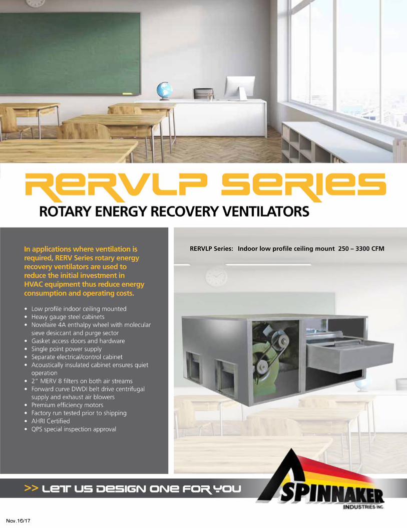
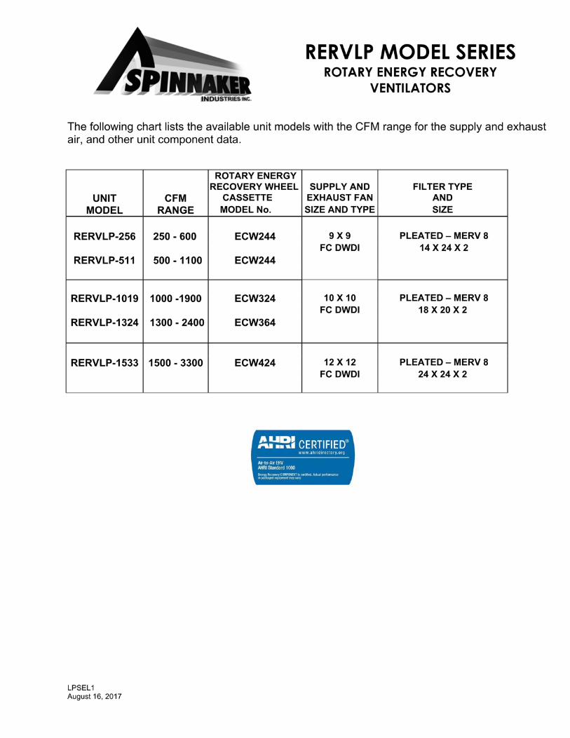
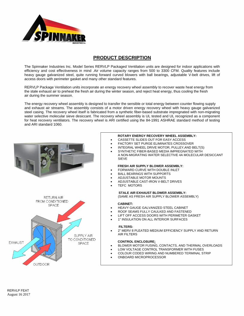
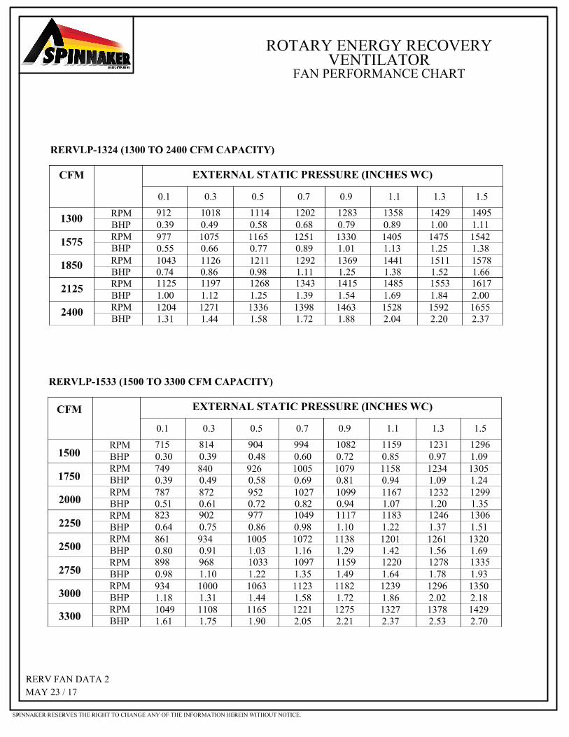
The Spinnaker Industries Inc. Model Series RERVLP Packaged Ventilation units are designed for indoor applications with efficiency and cost effectiveness in mind .Air volume capacity ranges from 500 to 3300 CFM. Quality features include heavy gauge galvanized steel, quite running forward curved blowers with ball bearings, adjustable V-belt drives, lift of access doors with perimeter gasket and many other standard features. RERVLP Package Ventilation units incorporate an energy recovery wheel assembly to recover waste heat energy from the stale exhaust air to preheat the fresh air during the winter season, and reject heat energy, thus cooling the fresh air during the summer season. The energy recovery wheel assembly is designed to transfer the sensible or total energy between counter flowing supply and exhaust air streams. The assembly consists of a motor driven energy recovery wheel with heavy gauge galvanized steel casing. The recovery wheel itself is fabricated from a synthetic fiber-based substrate impregnated with non-migrating water selective molecular sieve desiccant. The recovery wheel assembly is UL tested and UL recognized as a component for heat recovery ventilators. The recovery wheel is ARI certified using the 84-1991 ASHRAE standard method of testing and ARI standard 1060.
ROTARY ENERGY RECOVERY WHEEL ASSEMBLY: CASSETTE SLIDES OUT FOR EASY ACCESS FACTORY SET PURGE ELIMINATES CROSSOVER INTEGRAL WHEEL DRIVE MOTOR, PULLEY,AND BELT(S) SYNTHETIC FIBER-BASED MEDIA IMPREGNATED WITH
A NON-MIGRATING WATER SELECTIVE 4A MOLECULAR DESICCANT SIEVE
FRESH AIR SUPPLY BLOWER ASSEMBLY: FORWARD CURVE WITH DOUBLE INLET BALL BEARINGS WITH SUPPORTS ADJUSTABLE MOTOR MOUNTS ADJUSTABLE CAST-IRON V-BELT DRIVES TEFC MOTORS
STALE AIR EXHAUST BLOWER ASSEMBLY: (SAME AS FRESH AIR SUPPLY BLOWER ASSEMBLY) CABINET:
HEAVY GAUGE GALVANIZED STEEL CABINET ROOF SEAMS FULLY CAULKED AND FASTENED LIFT OFF ACCESS DOORS WITH PERIMETER GASKET 1" INSULATION ON ALL INTERIOR SURFACES
FILTERS:
2” MERV 8 PLEATED MEDIUM EFFICIENCY SUPPLY AND RETURN AIR FILTERS
CONTROL ENCLOSURE:
BLOWER MOTOR FUSING, CONTACTS, AND THERMAL OVERLOADS LOW VOLTAGE CONTROL TRANSFORMER WITH FUSES COLOUR CODED WIRING AND NUMBERED TERMINAL STRIP ONBOARD MICROPROCESSOR
1
RERVLP Optional Accessories
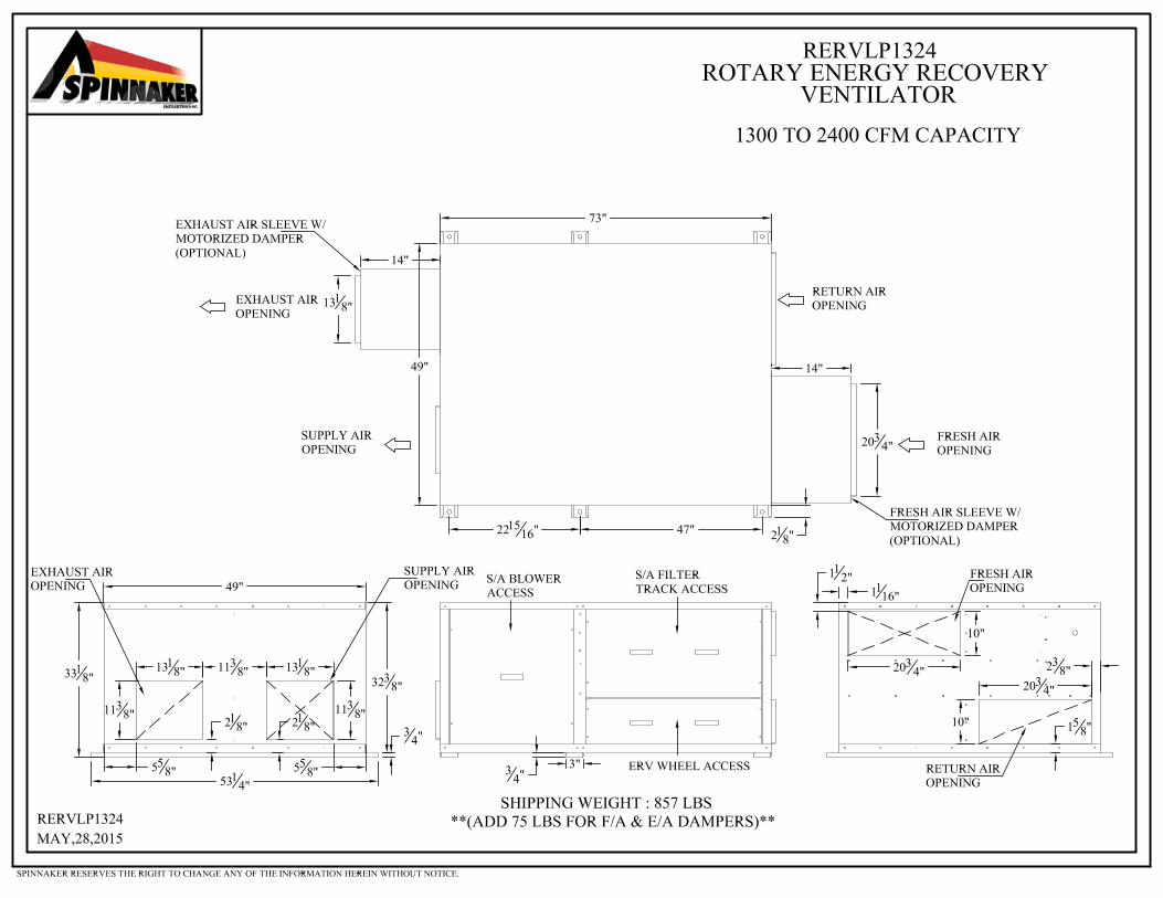
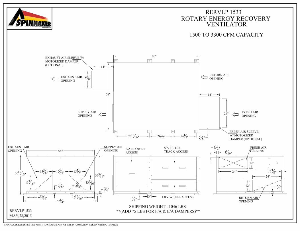
DUCT CONNECTION ARRANGEMENTS Arrangement H (Horizontal duct connections)
MISCELLANIOUS
Spring type vibration isolators for indoor hung or base mounted applications ( shipped loose for field install) Flexible duct connectors (Shipped loose for field installation on unit external duct connections) Sensible only energy recovery wheel
DAMPERS Fresh air inlet motorized low leakage parallel blade damper Exhaust discharge motorized low leakage parallel blade damper Gravity damper for exhaust discharge
FROST CONTROL
Exhaust only frost control Variable frequency drive (VFD) on energy recovery wheel motor for frost control Recirculation frost control
FREE COOLING CONTROLS
Fresh air enthalpy control for free cooling (Recovery wheel shutdown) Fresh air ambient temperature control for free cooling (Recovery wheel shutdown)
MISCELLANIOUS ELECTRICAL
Non-fused or fused disconnect switch Variable frequency drives (VFD) for supply and exhaust fan motors (Control by others) Two speed motors on supply and exhaust fans (Control by others) 7 day programmable timer Dirty filter pressure differential switches (Optional remote panel with indictor light(s) available) Remote on-off switch (Shipped loose) (Optional remote panel with indictor light(s) available) CO2 control for remote duct mount (Shipped loose for field installation) CO2 control for remote wall mount (Shipped loose for field installation) Smoke detector for remote duct mount ( Shipped loose for field installation) Recovery wheel rotation sensor (Optional remote panel with indictor light available) Digital CFM monitor – reads in CFM Economizer interlock ( Supply fan and energy recovery wheel stopped , exhaust fan runs ) Energy recovery wheel stop / jog control Microprocessor control system with temperature and humidity sensors Microprocessor control system remote read out panel Microprocessor control system BACNET card
LP OPI Aug 16 2017
RERVLP Optional Energy Saving Accessory Descriptions
Fresh air ambient temperature control for free cooling Two fresh air ambient temperature controls can be factory installed to de-energize the energy recovery wheel above 55F and below 75F. Both temperature controls are field adjustable to suit design conditions. This option prevents unnecessary heating of supply air through energy recovery during these outdoor temperatures. Option includes: Factory installed 2 ambient temperature controls
Fresh air enthalpy control for free cooling The fresh air enthalpy control has effectively the same function as the fresh air ambient temperature control. This option includes a fresh air temperature control and a logic controller with an enthalpy sensor. The fresh air temperature control energizes the energy recovery wheel below 55F. The enthalpy control senses the enthalpy of the fresh air, which is a combination of the air temperature and relative humidity. The enthalpy control will energize the energy recovery wheel above the set point which is actually a range of fresh air temperature -humidity combinations, for example, from approximately 63F 80% RH, to 82F 10% RH, for setting “A”. The enthalpy control has 4 field adjustable settings to suit design conditions. Option includes: Factory installed enthalpy control and ambient temperature control
LP OP2 Aug 16 2017
"RERVLP" PACKAGED ROTARY ENERGY RECOVERY VENTILATORS
INDOOR LOW PROFILE CEILING MOUNT 250-3300 CFM Capacities
Packaged recovery ventilation units shall be Spinnaker Industries Inc. Model Series RERVLP. Units shall be factory assembled, wired and tested prior to shipment. Units shall bear a QPS special inspection label. Field wiring shall require a single point power connection and a numbered terminal strip for low voltage remote wiring connections. UNIT CONSTRUCTION Unit construction to suit indoor applications. All exterior cabinet screws shall be Clima-seal with bonded washer. Unit casing shall be minimum 20 gauge galvanized steel. All interior cabinet surfaces shall be lined with 1” thick, 3 lbs/cu ft density foil faced insulation, with seems foil taped. Access doors and center partitions to be lined with 1/2 thick foil faced insulation. Access doors and panel to be lift off style. ENERGY RECOVERY WHEEL ASSEMBLY The energy recovery wheel assembly casing shall be constructed with heavy gauge galvanized steel, reinforced at sealing surfaces, removable end panels for drive access, inboard no-maintenance permanently sealed roller bearings for small assemblies, external pillow block bearings for large assemblies, and an adjustable non-contact neoprene bulb peripheral and inner seal. The wheel assembly shall slide in and out of the unit on a galvanized steel track for ease of inspection and maintenance. The wheel media shall be constructed of a corrugated synthetic fiber-based substrate impregnated with a non-migrating water selective 4A molecular sieve desiccant uniformly and permanently dispersed throughout the matrix structure. The wheel media shall be spirally wound to form a fluted honeycomb geometry so as to eliminate internal wheel bypass. Wheel layers that can be separated or spread apart by airflow are unacceptable due to the possibility of channeling and performance degradation. Face flatness of the wheel shall be maximized (+/- 0.032 inches) in order to minimize wear on inner seal surfaces and minimize cross leakage. The wheel shall be complete with a purge section, minimizing cross over of return air into supply air, with a non-contact bulb seal. Wheels with large pore size desiccants like silica gel, that are coated, bonded, or synthesized onto the media or without a purge section will not be accepted. The wheel shall consist of evenly spaced galvanized steel spokes, a galvanized steel outer band, and an aluminum center hub. The standard drive system shall consist of a drip proof motor, fixed pulley, and link type drive belt constructed from a high performance polyurethane elastomer reinforced with multiple plies of polyester fabric. The drive pulley and belt shall drive the wheel from inside the assembly casing. Wheels with drive pulleys and belts that are exposed will not be accepted. Single phase drive motors shall have integral automatic reset thermal overload protection. Three phase drive motors shall have a manual reset thermal overload mounted in the unit control enclosure. Wheel media shall be in accordance with NFPA, and be UL tested and UL recognized as a component for heating and heating-cooling appliance accessories. Energy recovery wheels shall be rigorously performance tested using the ASHRAE 84-1991 and ARI 1060 standard method of testing. Recovery wheels shall be ARI certified and must bear the ARI certification stamp.
FANS Supply and exhaust fans shall be forward curved double width double inlet belt drive with ball bearings. Fan drive shaft shall be polished with keyways for drive pulley mounting. Unit fans with machined flats on fan shafts for drive pulley mounting will not be accepted. Fans shall have ball bearings suitable for operation in ambient temperatures of –65 to 250 deg. F with a minimum L10 life in excess of 100,000 hours at maximum cataloged operating speeds. Fan bearings shall be permanently lubricated and sealed, mounted in resilient neoprene rings. Fan housings shall have extruded holes for base side mounting. Fans in units with air flow capacity greater than 2500 CFM shall have welded steel angle frames. Fan motors shall be rated continuous duty, ball bearing construction, and have class F insulation. Variable pitch v-belt drives, of cast iron construction and adjustable motor mounts to be provided. Units with fans, motors, and drives that do not meet the above criteria will not be accepted. FILTERS The supply entering and exhaust entering sides of the recovery wheel shall be complete with 2" pleated MERV 7 medium efficiency filters. Units without supply and exhaust filters will not be accepted. CONTROLS AND ELECTRICAL Unit controls shall be mounted within an integral enclosure with an exterior lift off access panel. The exterior lift off access panel shall be the same construction as the other unit access panels Unit controls shall include: supply and exhaust fan motor fuses, contactors, and manual reset thermal overloads, energy recovery wheel drive motor contactor, and control transformers with primary and secondary fusing. Unit wiring shall be color coded with a numbered terminal strip for low voltage wiring and field connections. Unit shall have single point power input terminals. Units without separate motor fusing and contactors will not be accepted ACCEPTANCE Verify prior to bidding that the units meet the specified construction, and scheduled performance and electrical characteristics. Units that do not meet the specified construction, accessories, or scheduled performance and electrical characteristics will not be accepted. .
ADDITIONAL ACCESSORIES FRESH AIR MOTORIZED INLET DAMPER Units shall be complete with factory installed and wired fresh air inlet two position gear driven motorized damper constructed with minimum 20 gauge galvanized steel, stainless steel side seals. Damper motor shall be spring return, 24 volt powered, and complete with an end switch for unit fan activation when damper is fully open. EXHAUST AIR MOTORIZED DISCHARGE DAMPER Units shall be complete with factory installed and wired exhaust air discharge two position gear driven motorized damper constructed with minimum 20 gauge galvanized steel, stainless steel side seals. Damper motor shall be spring return, 24 volt powered, and complete with an end switch for unit fan activation when damper is fully open. EXHAUST ONLY FROST CONTROL Units shall include a pressure differential switch and an adjustable on delay timer relay. If frost occurs, the pressure increase cause the pressure differential switch to shut the supply fan off and leave the exhaust fan operating until the warm indoor air defrosts the wheel and the pressure across the wheel is reduced to normal. VARIABLE FREQUENCY DRIVE FOR FROST CONTROL The variable speed frost control option is an exhaust air temperature humidity function that allows for continuous ventilation by reducing the recovery wheel rotational speed. The recovery wheel is modulated to maintain an exhaust air humidity level of 98% to prevent frost formation. This option may not be suitable in areas with outdoor winter ambient design conditions below - 10°F .
OTHER ACCESSORIES
Spinnaker Industries maintains a continuous improvement policy , therefore this information is subject to change without notice
28062017
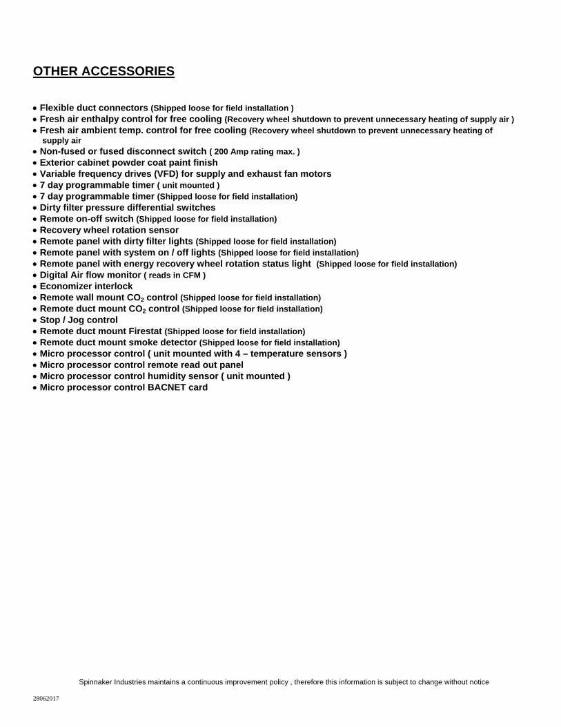
Flexible duct connectors (Shipped loose for field installation ) Fresh air enthalpy control for free cooling (Recovery wheel shutdown to prevent unnecessary heating of supply air ) Fresh air ambient temp. control for free cooling (Recovery wheel shutdown to prevent unnecessary heating of supply air Non-fused or fused disconnect switch ( 200 Amp rating max. ) Exterior cabinet powder coat paint finish Variable frequency drives (VFD) for supply and exhaust fan motors 7 day programmable timer ( unit mounted ) 7 day programmable timer (Shipped loose for field installation) Dirty filter pressure differential switches Remote on-off switch (Shipped loose for field installation) Recovery wheel rotation sensor Remote panel with dirty filter lights (Shipped loose for field installation) Remote panel with system on / off lights (Shipped loose for field installation) Remote panel with energy recovery wheel rotation status light (Shipped loose for field installation) Digital Air flow monitor ( reads in CFM ) Economizer interlock Remote wall mount CO2 control (Shipped loose for field installation) Remote duct mount CO2 control (Shipped loose for field installation) Stop / Jog control Remote duct mount Firestat (Shipped loose for field installation) Remote duct mount smoke detector (Shipped loose for field installation) Micro processor control ( unit mounted with 4 – temperature sensors ) Micro processor control remote read out panel Micro processor control humidity sensor ( unit mounted ) Micro processor control BACNET card
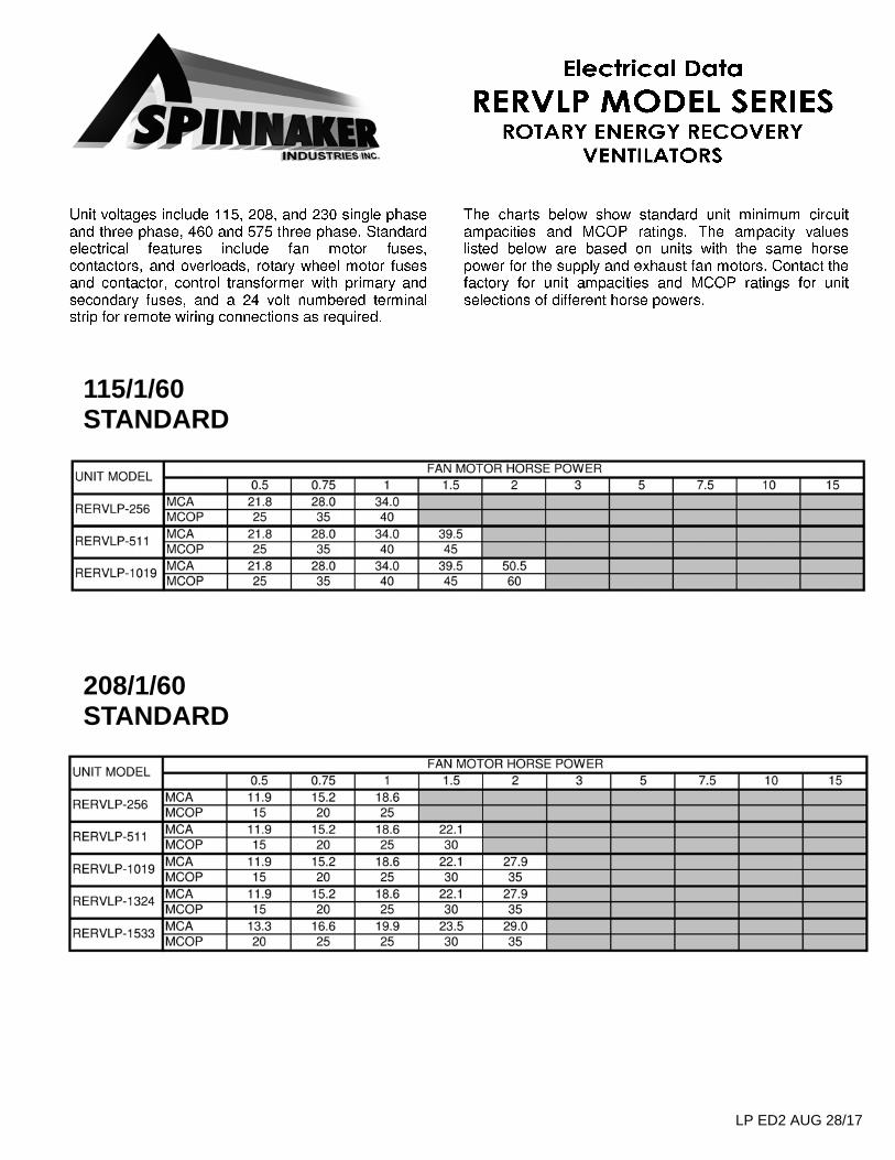
115/1/60 STANDARD
208/1/60 STANDARD
LP ED2 AUG 28/17
LP ED2 AUG 28/17
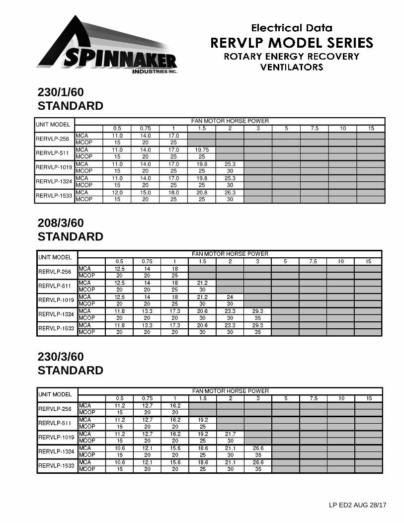
230/1/60 STANDARD
208/3/60 STANDARD
230/3/60 STANDARD
LP ED2 AUG 28/17
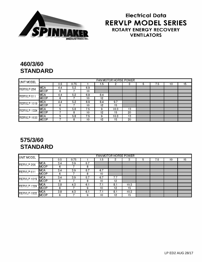
460/3/60 STANDARD
575/3/60 STANDARD
RERV WARRANTY REV Sept 28 / 11
RERVLP Limited Warranty
COVERAGE AND TERMS RERV Model Series units and all RERV accessories as manufactured by Spinnaker Industries, are warranted to the original buyer to be free from defects in materials or workmanship provided that these units and accessories have been installed and maintained in accordance with instructions and operated under normal conditions. Spinnaker Industries sole obligation under this Limited Warranty is to repair or replace, at its opinion, free of charge to the customer (except as provided below), FOB factory, any part determined by Spinnaker Industries (in its sole discretion) to be defective. Warranty terms, from original ship date are as follows: Energy recovery wheel assembly
(excluding drive belts, seals, and motors)….……..………5 Years Recovery wheel belts, seals, and motors…………………2 Years All other components………………………………………..1 Year
EXCLUSIONS Spinnaker Industries Limited Warranty does not cover defects, reduced performance, or failure caused, directly or indirectly, by improper installation, abuse, misuse, misapplication, improper maintenance, lack of maintenance, negligence, accident, or normal deterioration, including wear and tear. This Limited Warranty shall not apply to items that require replacement due to normal wear i.e. fan drive belts, filters, etc., or to failures, defects, or reduced performance resulting, directly or indirectly, from use of its products exposed to corrosive gasses or liquids. Warranty claims that are not supported with a copy of the original start up report will not be considered. Spinnaker Industries Limited Warranty does not include costs for transportation (including, without limitation, freight and return freight charges, costs, and insurance), costs for removal or re-installation of parts or equipment, cranes and hoisting, premiums for overtime, labor for performing repairs or replacement made in the field, roofing contractors or any other sub trades. Spinnaker Industries is not responsible for damages occurring during transport of any product to or from its facilities. RETURN PROCEDURE To return defective parts under these warranty terms, please contact Spinnaker Industries at 1-800-932-6210 to confirm the ship to address. The serial number located on the rating label of the unit must be provided so that the original ship date of the unit can be verified. All defective parts must be authorized for return and shipped pre-paid to Spinnaker Industries for inspection. A purchase order must be received prior to shipment of repaired or replacement parts. Repaired or replacement parts will be invoiced and shipped collect FOB Factory. A credit will be issued only if the defective parts are deemed the responsibility of Spinnaker Industries. Spinnaker Industries is not responsible for any damage or loss occurring during shipment to or from Spinnaker Industries. THE OBLIGATION AND LIABILITY OF Spinnaker Industries UNDER THIS LIMITED WARRANTY DOES NOT INCLUDE LOSSES, DIRECT OR INDIRECT, FOR INCIDENTAL OR CONSEQUENTIAL DAMAGES. THIS LIMITED WARRANTY IS PROVIDED EXCLUSIVELY TO THE ORIGINAL BUYER OF PRODUCTS AND MAY NOT BE ASSIGNED OR OTHERWISE TRANSFERRED. THIS LIMITED WARRANTY IS IN LIEU OF ALL OTHER WARRANTIES, EXPRESED OR IMPLIED, INCLUDING WARRANTIES OF MERCHANTABILITY AND FITNESS FOR A PARTICULAR PURPOSE, AND THERE ARE NO WARRANTIES WHICH EXTEND BEYOND THE DESCRIPTION ON THE FACE HEREOF.