Embed Size (px)
Citation preview
Lecture 5:
Temperature and LightMeasurement
1
Temperature Measurement
• Temperature is without doubt the most widely measured variable.
• In the process control of chemical reactions, temperature control is of major importance, since chemical reactions are temperature-dependent.
• All physical parameters are temperature-dependent, making it necessary in most cases to measure temperature along with the physical parameter, so that temperature corrections can be made to achieve accurate parameter measurements.
2
Temperature sensors• There are many properties that change with temperature and can be used
as basis of temperature sensors.
• The following are some of the commonly used temperature sensors:
Expansion thermometers; Resistor-temperature detectors (RTD); Thermistors; Thermocouples; Pyrometer; and Semiconductors.
3
Expansion Thermometers
Many materials expand when heated. This forms the basis for expansion-based temperature sensors such as:
Liquid in glass thermometer The bimetallic strip
4
Liquid in glass thermometers• Liquid in glass thermometers using mercury were, by far, the most
common direct visual reading thermometer.
• Mercury has the advantage of not wetting the glass; that is, the mercury cleanly traverses the glass tube without breaking into globules or coating the tube.
• The operating range of the mercury thermometer is from −35° to +450°C. and the freezing point of mercury −38°C.
• The toxicity of mercury, ease of breakage, the introduction of cost-effective, accurate, and easily read digital thermometers, has brought about the demise of the mercury thermometer for room and clinical measurements.
5
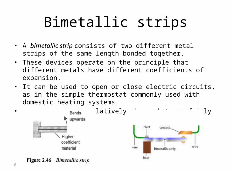
Bimetallic strips• A bimetallic strip consists of two different metal strips of the same length
bonded together.• These devices operate on the principle that different metals have different
coefficients of expansion.• It can be used to open or close electric circuits, as in the simple
thermostat commonly used with domestic heating systems.• They are robust, relatively cheap, but are fairly slow.
6

Resistance temperature detectors (RTDs)
• The resistance of most metals increases in a reasonably linear way with temperature and can be represented by the equation:
RT = R0(1+T)
• where RT is the resistance at a temperature T °C, R0 the resistance at 0°C and is constant for the metal, termed the temperature coefficient of resistance.
• Resistance temperature detectors (RTDs) are simple resistive elements in the form of coils of metal wire, e.g. platinum, nickel or copper alloys.
• Resistance devices are normally measured using a Wheatstone bridge, or supplied from a constant current source. Care should be taken to prevent the electrical current from heating the device and causing erroneous readings.
7
Example
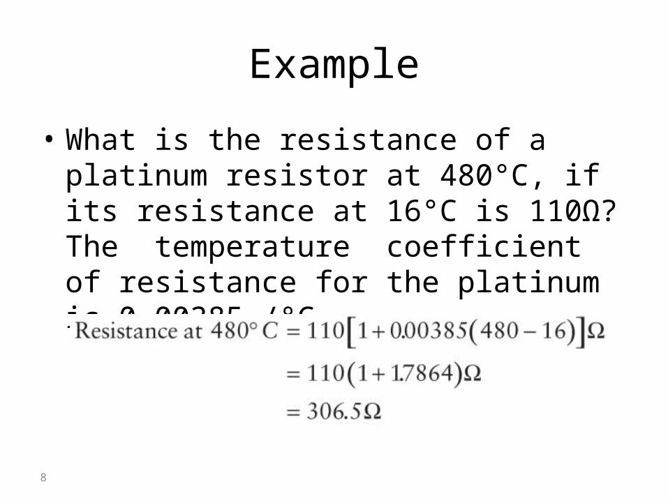
• What is the resistance of a platinum resistor at 480°C, if its resistance at 16°C is 110Ω? The temperature coefficient of resistance for the platinum is 0.00385 /°C.
8
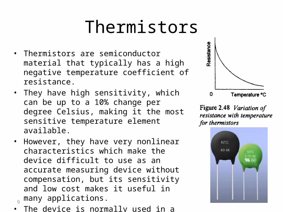
Thermistors• Thermistors are semiconductor material that
typically has a high negative temperature coefficient of resistance.
• They have high sensitivity, which can be up to a 10% change per degree Celsius, making it the most sensitive temperature element available.
• However, they have very nonlinear characteristics which make the device difficult to use as an accurate measuring device without compensation, but its sensitivity and low cost makes it useful in many applications.
• The device is normally used in a bridge circuit.• The typical response time is from 0.5 to 5 seconds.• When in use, care has to be taken to minimize the
effects of internal heating. 9
Thermocouple
• In 1821, the physicist Thomas Johann Seebeck discovered that when any conductor is subjected to a thermal gradient, it will generate a voltage. This is now known as the thermoelectric effect or Seebeck effect.
• This effect is the basis for the thermocouple device.
10
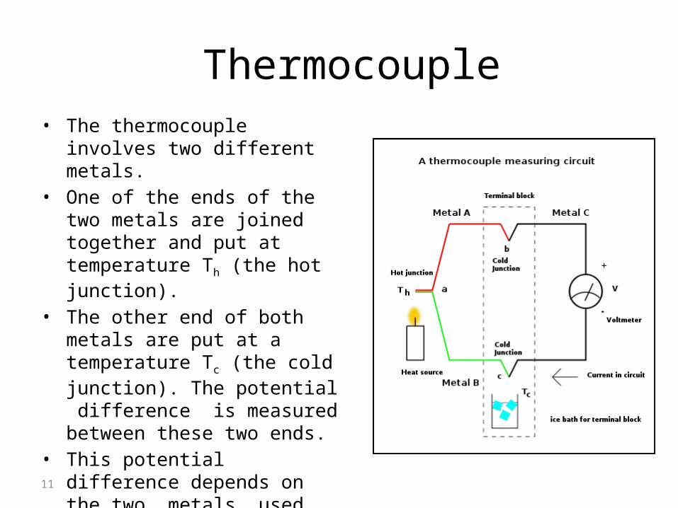
Thermocouple • The thermocouple involves two
different metals. • One of the ends of the two metals
are joined together and put at temperature Th (the hot junction).
• The other end of both metals are put at a temperature Tc (the cold junction). The potential difference is measured between these two ends.
• This potential difference depends on the two metals used and the temperature difference between the two junctions.
11
Thermocouple
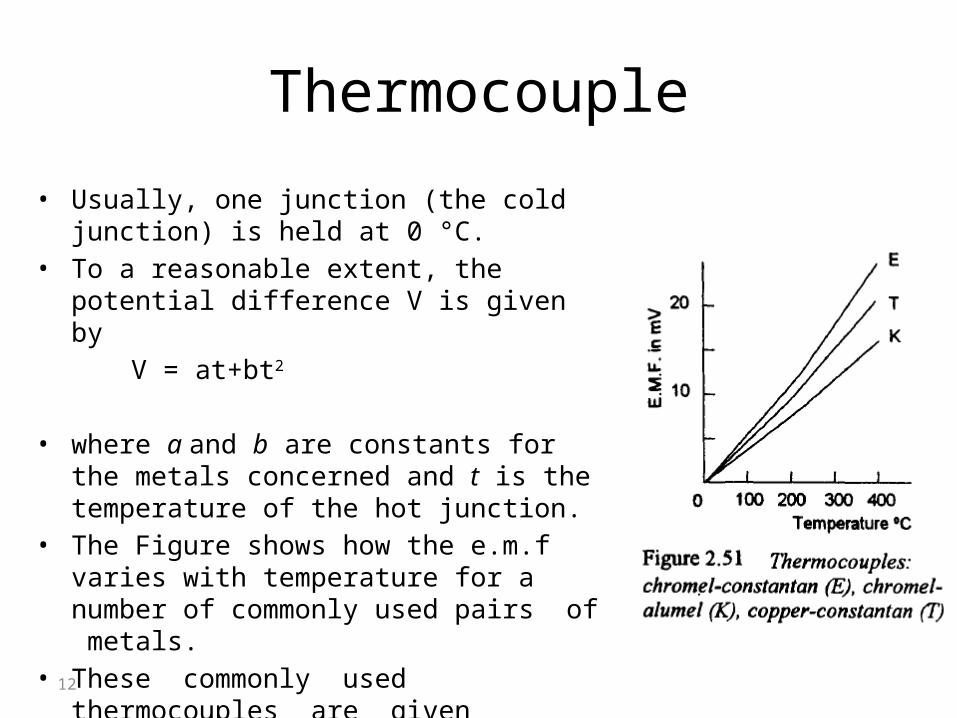
• Usually, one junction (the cold junction) is held at 0 °C.
• To a reasonable extent, the potential difference V is given by
V = at+bt2
• where a and b are constants for the metals concerned and t is the temperature of the hot junction.
• The Figure shows how the e.m.f varies with temperature for a number of commonly used pairs of metals.
• These commonly used thermocouples are given reference letters.
12
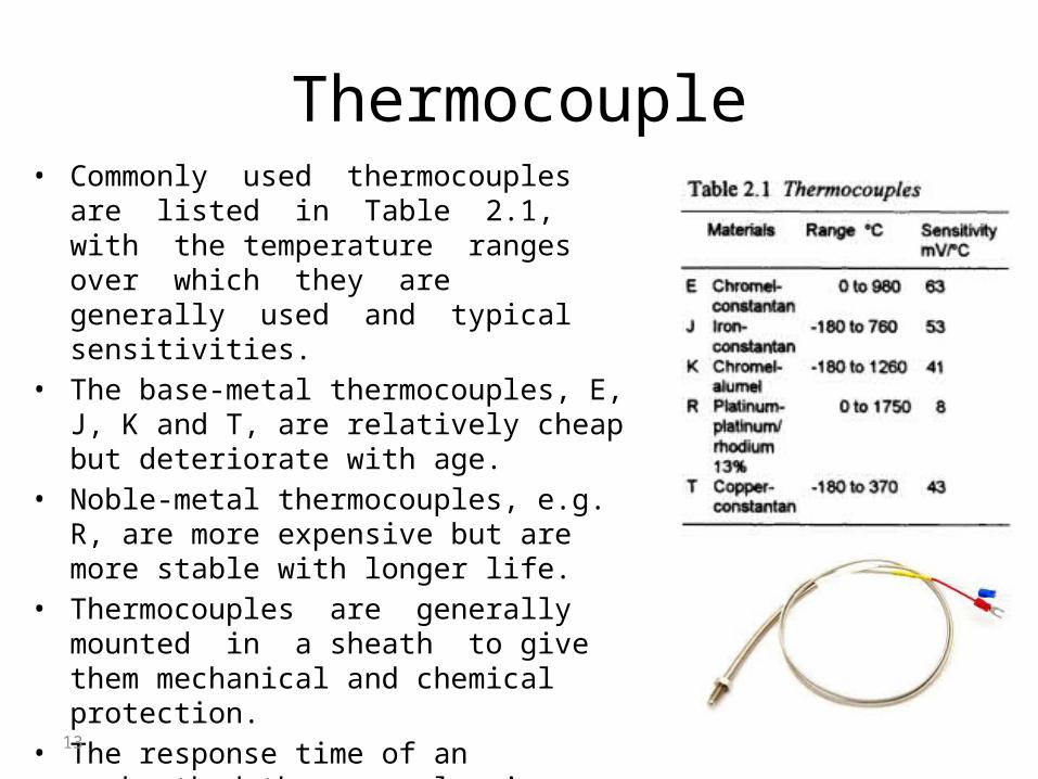
Thermocouple• Commonly used thermocouples are listed in
Table 2.1, with the temperature ranges over which they are generally used and typical sensitivities.
• The base-metal thermocouples, E, J, K and T, are relatively cheap but deteriorate with age.
• Noble-metal thermocouples, e.g. R, are more expensive but are more stable with longer life.
• Thermocouples are generally mounted in a sheath to give them mechanical and chemical protection.
• The response time of an unsheathed thermocouple is very fast. With a sheath this may be increased to as much as a few seconds if a large sheath is used.
13
Thermocouple• Standard tables are available for metals usually used for
thermocouples giving the e.m.fs at different temperatures assuming that the reference (cold) junction is at 0°C.
• As the thermocouple can be used with the reference junction at a temperature other than 0°C, a correction has to be applied before the tables can be used.
• The correction is applied using what is known as the law of intermediate temperatures, namely:
Et1,0 = Et1,t2 + Et2,0
• Where Et1,t2 is the emf between the two junction when the hot junction is at temperature t1 and the cold junction is at temperature t2.
14
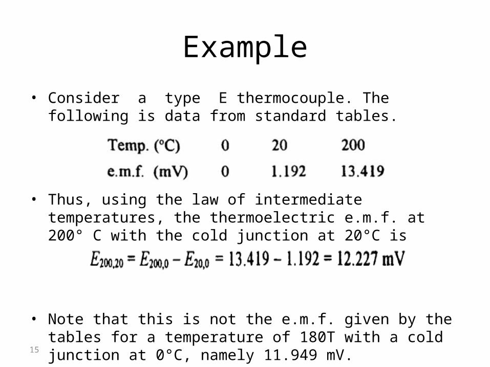
Example• Consider a type E thermocouple. The following is data from
standard tables.
• Thus, using the law of intermediate temperatures, the thermoelectric e.m.f. at 200° C with the cold junction at 20°C is
• Note that this is not the e.m.f. given by the tables for a temperature of 180T with a cold junction at 0°C, namely 11.949 mV.
15
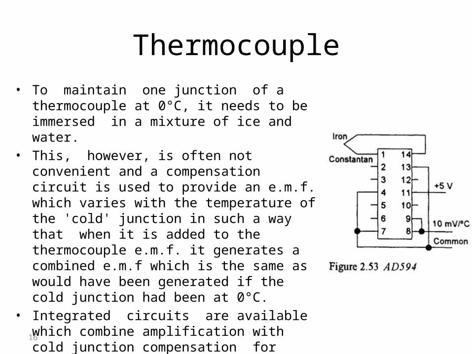
Thermocouple• To maintain one junction of a thermocouple at 0°C,
it needs to be immersed in a mixture of ice and water. • This, however, is often not convenient and a
compensation circuit is used to provide an e.m.f. which varies with the temperature of the 'cold' junction in such a way that when it is added to the thermocouple e.m.f. it generates a combined e.m.f which is the same as would have been generated if the cold junction had been at 0°C.
• Integrated circuits are available which combine amplification with cold junction compensation for thermocouples, e.g. the Analog Devices AD594. When AD594 is used with a +5V supply and a constantan-iron thermocouple, it gives an output of 10 mV/°C.
16
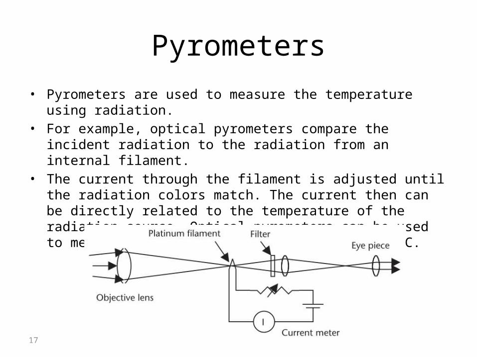
Pyrometers• Pyrometers are used to measure the temperature using radiation.• For example, optical pyrometers compare the incident radiation to the
radiation from an internal filament. • The current through the filament is adjusted until the radiation colors
match. The current then can be directly related to the temperature of the radiation source. Optical pyrometers can be used to measure temperatures from 1,100° to 2,800°C.
17
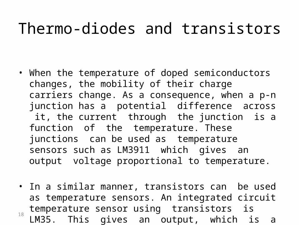
Thermo-diodes and transistors
• When the temperature of doped semiconductors changes, the mobility of their charge carriers change. As a consequence, when a p-n junction has a potential difference across it, the current through the junction is a function of the temperature. These junctions can be used as temperature sensors such as LM3911 which gives an output voltage proportional to temperature.
• In a similar manner, transistors can be used as temperature sensors. An integrated circuit temperature sensor using transistors is LM35. This gives an output, which is a linear function of temperature, of 10 mV/°C when the supply voltage is 5 V.
18
Light Measurement
19
Photocells
• Photocells are used for the detection and conversion of light intensity into electrical signals.
• Photocells can be classified as:
photovoltaic, photoconductive, photo-emissive, and semiconductor.
20
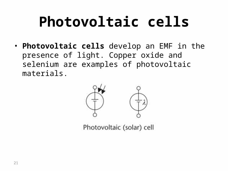
Photovoltaic cells
• Photovoltaic cells develop an EMF in the presence of light. Copper oxide and selenium are examples of photovoltaic materials.
21
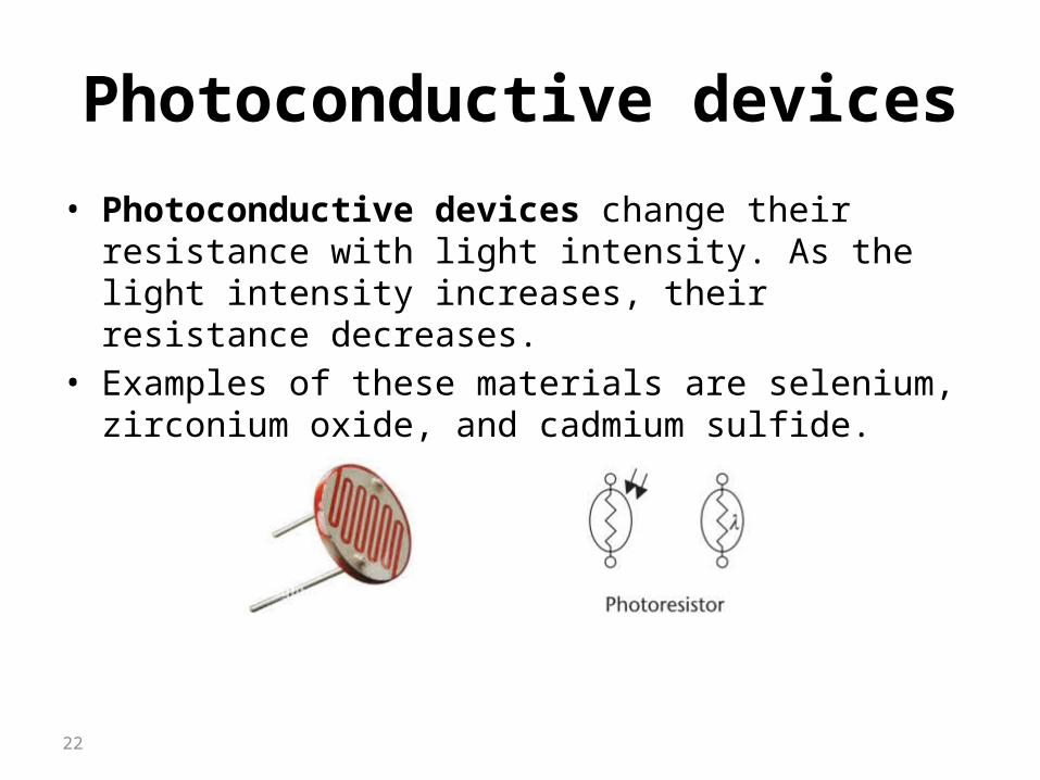
Photoconductive devices
• Photoconductive devices change their resistance with light intensity. As the light intensity increases, their resistance decreases.
• Examples of these materials are selenium, zirconium oxide, and cadmium sulfide.
22
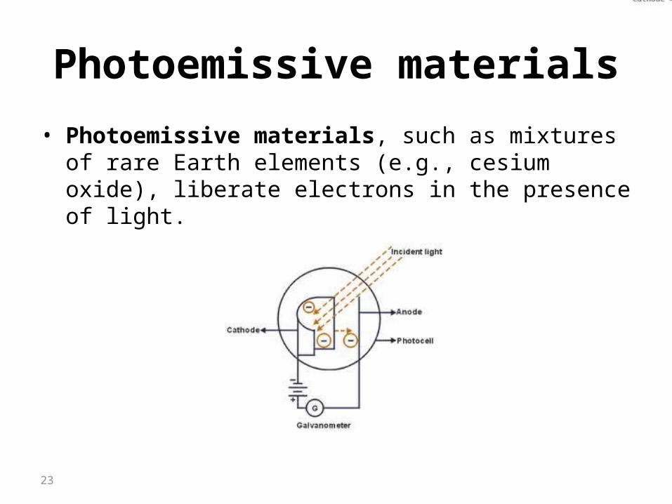
Photoemissive materials
• Photoemissive materials, such as mixtures of rare Earth elements (e.g., cesium oxide), liberate electrons in the presence of light.
23
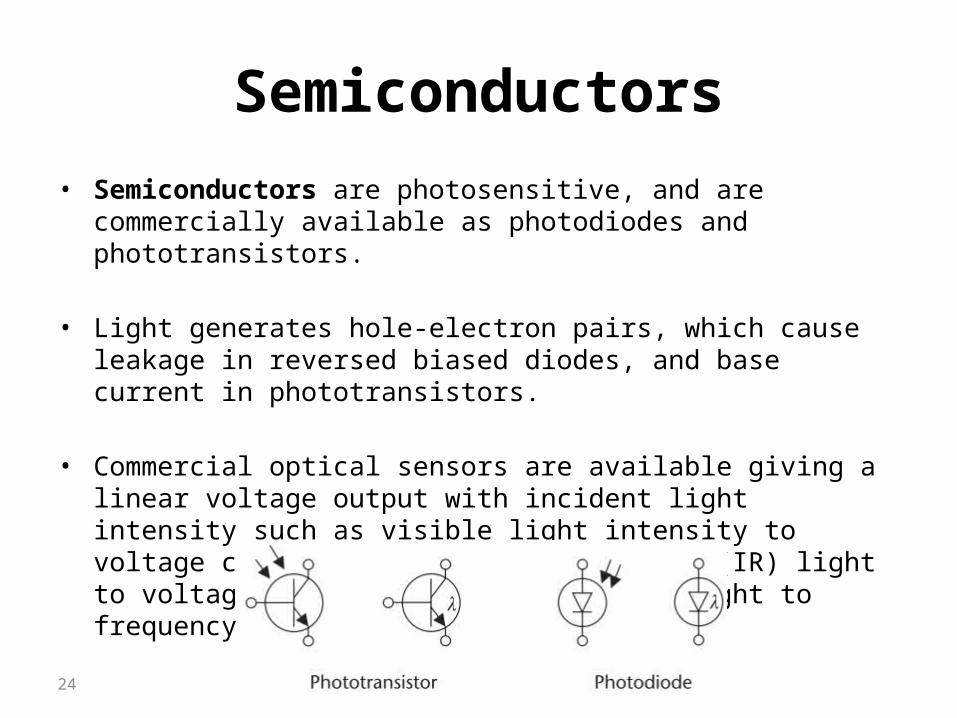
Semiconductors• Semiconductors are photosensitive, and are commercially available as
photodiodes and phototransistors.
• Light generates hole-electron pairs, which cause leakage in reversed biased diodes, and base current in phototransistors.
• Commercial optical sensors are available giving a linear voltage output with incident light intensity such as visible light intensity to voltage converters (TSL 250), Infrared (IR) light to voltage converters (TSL 260), and light to frequency converters (TSL 230).
24
Light Sources
• Incandescent light is produced by electrically heating a resistive filament, or by the burning of certain combustible materials. A large portion of the energy emitted is in the infrared spectrum, as well as the visible spectrum.
• Atomic type sources cover gas discharge devices, such as neon and fluorescent lights.
• Laser emissions are obtained by excitation of the atoms of certain elements.
• Semiconductor diodes, such as LEDs, are the most common commercially available light sources used in industry. When forward biased, the diodes emit light in the visible or IR region.
25