Embed Size (px)
Citation preview
BUSH HOG®
ASSEMBLY � OPERATION � MAINTENANCE$4.00
Operator’s Manual
2315FLEX-WING ROTARY CUTTER
797 Part No. 91885

CONGRATULATIONS!You have invested in the best implement of its type on the market today.
The care you give your Bush Hog implement will greatly determine your satisfactionwith its performance and its service life. We urge a careful study of this manual to provideyou with a thorough understanding of your new implement before operating, as well assuggestions for operation and maintenance.
If your manual should become lost or destroyed, Bush Hog will be glad to provide you witha new copy. Order from Bush Hog, P. O. Box 1039, Selma, Alabama 36702-1039. Most of ourmanuals can also be downloaded from our website at www.bushhog.com.
As an authorized Bush Hog dealer, we stock genuine Bush Hog parts which aremanufactured with the same precision and skill as our original equipment. Our trainedservice personnel are well informed on methods required to service Bush Hog equipment,and are ready and able to help you.
Should you require additional information or assistance, please contact us.
YOUR AUTHORIZEDBUSH HOG DEALER
BECAUSE BUSH HOG MAINTAINS AN ONGOINGPROGRAM OF PRODUCT IMPROVEMENT, WE RESERVE THE RIGHT TO MAKE IMPROVEMENTS IN DESIGN OR CHANGES IN SPECIFICATIONS WITH-OUT INCURRING ANY OBLIGATION TO INSTALL THEM ON UNITS PREVIOUSLY SOLD.
BECAUSE OF THE POSSIBILITY THAT SOMEPHOTOGRAPHS IN THIS MANUAL WERE TAKEN OF PROTOTYPE MODELS, PRODUCTION MODELS MAY VARY IN SOME DETAIL. IN ADDITION, SOMEPHOTOGRAPHS MAY SHOW SHIELDS REMOVED FOR PURPOSES OF CLARITY. NEVER OPERATETHIS IMPLEMENT WITHOUT ALL SHIELDS IN PLACE.

2315 ROTARY CUTTERTABLE OF CONTENTS
SECTION/PARA PAGEWarranty.................................................2Dealer Preparation Check List ...............3Safety Precautions.................................4Federal Laws and Regulations ..............5
I. INTRODUCTION & DESCRIPTION ......61-1 Introduction ......................................61-2 Description.......................................6
II. PREPARATION FOR USE.....................72-1 Attaching To Tractor ........................72-2 Optional Valve Mounting
Bracket Installation ..........................72-3 Pitch Adjustment..............................82-4 Wing Adjustment..............................8
III.OPERATING INSTRUCTIONS ..............93-1 General Instructions.........................93-2 Transporting.....................................93-3 Operation .........................................9
SECTION/PARA PAGE
RETAIL CUSTOMER’S RESPONSIBILITYUNDER THE BUSH HOG WARRANTY
It is the Retail Customer and/or Operator’s responsibility to read the Operator’s Manual, tooperate, lubricate, maintain and store the product in accordance with all instructions andsafety procedures. Failure of the operator to read the Operator’s Manual is a misuse of thisequipment.
It is the Retail Customer and/or Operator’s responsibility to inspect the product and to haveany part(s) repaired or replaced when continued operation would cause damage or exces-sive wear to other parts or cause a safety hazard.
It is the Retail Customer’s responsibility to deliver the product to the authorized Bush HogDealer, from whom he purchased it, for service or replacement of defective parts which arecovered by warranty. Repairs to be submitted for warranty consideration must be made with-in forty-five (45) days of failure.
It is the Retail Customer’s responsibility for any cost incurred by the Dealer for traveling to orhauling of the product for the purpose of performing a warranty obligation or inspection.
1
IV.MAINTENANCE ..................................104-1 Maintenance Check List ................104-2 Lubrication .....................................114-3 Blade Replacement .......................144-4 Blade Pan Removal .......................144-5 Blade Holder Assembly
Removal and Installation................144-6 Slip Clutch Operational Check.......154-7 Slip Clutch Adjustment...................154-8 Troubleshooting .............................15
V. ASSEMBLY..........................................165-1 Model 2315 Assembly ...................16Hydraulic Diagrams..............................21Axle Arm Diagram................................23Safety Decals.......................................24Torque Specifications...........................25

BUSH HOG®
LIMITED WARRANTY✯✯✯✯✯✯✯✯✯✯✯✯✯✯✯✯✯✯✯✯✯✯✯✯✯✯✯✯✯✯✯
Bush Hog warrants to the original purchaser of any new Bush Hog equipment, purchased from anauthorized Bush Hog dealer, that the equipment be free from defects in material and workmanship for a periodof one (1) year for non-commercial, state, and municipalities’ use and ninety (90) days for commercial use fromdate of retail sale. The obligation of Bush Hog to the purchaser under this warranty is limited to the repair orreplacement of defective parts.
Replacement or repair parts installed in the equipment covered by this limited warranty are warrantedfor ninety (90) days from the date of purchase of such part or to the expiration of the applicable new equip-ment warranty period, whichever occurs later. Warranted parts shall be provided at no cost to the user at anauthorized Bush Hog dealer during regular working hours. Bush Hog reserves the right to inspect any equip-ment or parts which are claimed to have been defective in material or workmanship.
DISCLAIMER OF IMPLIED WARRANTIES & CONSEQUENTIAL DAMAGES
Bush Hog’s obligation under this limited warranty, to the extent allowed by law, is in lieu of all war-ranties, implied or expressed, INCLUDING IMPLIED WARRANTIES OF MERCHANTABILITY AND FITNESSFOR A PARTICULAR PURPOSE and any liability for incidental and consequential damages with respect tothe sale or use of the items warranted. Such incidental and consequential damages shall include but not belimited to: transportation charges other than normal freight charges; cost of installation other than costapproved by Bush Hog; duty; taxes; charges for normal service or adjustment; loss of crops or any other loss ofincome; rental of substitute equipment, expenses due to loss, damage, detention or delay in the delivery ofequipment or parts resulting from acts beyond the control of Bush Hog.
THIS LIMITED WARRANTY SHALL NOT APPLY:
1. To vendor items which carry their own warranties, such as engines, tires, and tubes.
2. If the unit has been subjected to misapplication, abuse, misuse, negligence, fire or other accident.
3. If parts not made or supplied by Bush Hog have been used in connection with the unit, if, in the sole judge-ment of Bush Hog such use affects its performance, stability or reliability.
4. If the unit has been altered or repaired outside of an authorized Bush Hog dealership in a mannerwhich, in the sole judgement of Bush Hog, affects its performance, stability or reliability.
5. To normal maintenance service and normal replacement items such as gearbox lubricant, hydraulic fluid, worn blades, or to normal deterioration of such things as belts and exterior finish due to use or exposure.
6. To expendable or wear items such as teeth, chains, sprockets, belts, springs and any other items that in thecompany’s sole judgement is a wear item.
NO EMPLOYEE OR REPRESENTATIVE OF BUSH HOG IS AUTHORIZED TO CHANGE THIS LIM-ITED WARRANTY IN ANY WAY OR GRANT ANY OTHER WARRANTY UNLESS SUCH CHANGE IS MADE IN WRITING AND SIGNED BY BUSH HOG’S SERVICE MANAGER, POST OFFICE BOX 1039, SELMA,ALABAMA 36702-1039.
✯✯✯✯✯✯✯✯✯✯✯✯✯✯✯✯✯✯✯✯✯✯✯✯✯✯✯✯✯✯✯Record the model number, serial number and datepurchased. This information will be helpful to your
dealer if parts or service are required.
MAKE CERTAIN THE WARRANTY REGISTRATIONCARD HAS BEEN FILED WITH BUSH HOG/SELMA, ALABAMA
MODEL NUMBER
SERIAL NUMBER
DATE OF RETAIL SALE
2
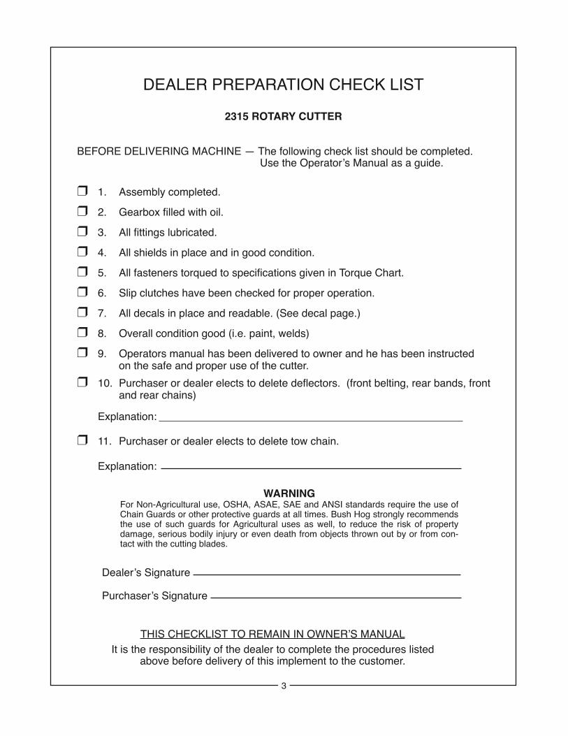
DEALER PREPARATION CHECK LIST
2315 ROTARY CUTTER
BEFORE DELIVERING MACHINE — The following check list should be completed.Use the Operator’s Manual as a guide.
❒ 1. Assembly completed.
❒ 2. Gearbox filled with oil.
❒ 3. All fittings lubricated.
❒ 4. All shields in place and in good condition.
❒ 5. All fasteners torqued to specifications given in Torque Chart.
❒ 6. Slip clutches have been checked for proper operation.
❒ 7. All decals in place and readable. (See decal page.)
❒ 8. Overall condition good (i.e. paint, welds)
❒ 9. Operators manual has been delivered to owner and he has been instructedon the safe and proper use of the cutter.
❒ 10. Purchaser or dealer elects to delete deflectors. (front belting, rear bands, front and rear chains)
Explanation:
❒ 11. Purchaser or dealer elects to delete tow chain.
Explanation:
Dealer’s Signature
Purchaser’s Signature
THIS CHECKLIST TO REMAIN IN OWNER’S MANUALIt is the responsibility of the dealer to complete the procedures listed
above before delivery of this implement to the customer.
WARNINGFor Non-Agricultural use, OSHA, ASAE, SAE and ANSI standards require the use ofChain Guards or other protective guards at all times. Bush Hog strongly recommendsthe use of such guards for Agricultural uses as well, to reduce the risk of propertydamage, serious bodily injury or even death from objects thrown out by or from con-tact with the cutting blades.
3
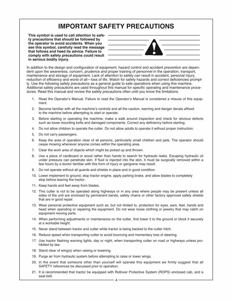
IMPORTANT SAFETY PRECAUTIONSThis symbol is used to call attention to safe-ty precautions that should be followed by the operator to avoid accidents. When you see this symbol, carefully read the message that follows and heed its advice. Failure to comply with safety precautions could result in serious bodily injury.
In addition to the design and configuration of equipment, hazard control and accident prevention are depen-dent upon the awareness, concern, prudence and proper training of personnel in the operation, transport, maintenance and storage of equipment. Lack of attention to safety can result in accident, personal injury, reduction of efficiency and worst of all—loss of life. Watch for safety hazards and correct deficiencies prompt-ly. Use the following safety precautions as a general guide to safe operations when using this machine. Additional safety precautions are used throughout this manual for specific operating and maintenance proce-dures. Read this manual and review the safety precautions often until you know the limitations.
1. Read the Operator’s Manual. Failure to read the Operator’s Manual is considered a misuse of this equip-ment.
2. Become familiar with all the machine’s controls and all the caution, warning and danger decals affixed to the machine before attempting to start or operate.
3. Before starting or operating the machine, make a walk around inspection and check for obvious defects such as loose mounting bolts and damaged components. Correct any deficiency before starting.
4. Do not allow children to operate the cutter. Do not allow adults to operate it without proper instruction.
5. Do not carry passengers.
6. Keep the area of operation clear of all persons, particularly small children and pets. The operator should cease mowing whenever anyone comes within the operating area.
7. Clear the work area of objects which might be picked up and thrown.
8. Use a piece of cardboard or wood rather than hands to search for hydraulic leaks. Escaping hydraulic oil under pressure can penetrate skin. If fluid is injected into the skin, it must be surgically removed within a few hours by a doctor familiar with this form of injury or gangrene may result.
9. Do not operate without all guards and shields in place and in good condition.
10. Lower implement to ground, stop tractor engine, apply parking brake, and allow blades to completely stop before leaving the tractor.
11. Keep hands and feet away from blades.
12. This cutter is not to be operated along highways or in any area where people may be present unless all sides of the unit are enclosed by permanent bands, safety chains or other factory approved safety shields that are in good repair.
13. Wear personal protective equipment such as, but not limited to, protection for eyes, ears, feet, hands and head when operating or repairing the equipment. Do not wear loose clothing or jewelry that may catch on equipment moving parts.
14. When performing adjustments or maintenance on the cutter, first lower it to the ground or block it securely at a workable height.
15. Never stand between tractor and cutter while tractor is being backed to the cutter hitch.
16. Reduce speed when transporting cutter to avoid bouncing and momentary loss of steering.
17. Use tractor flashing warning lights, day or night, when transporting cutter on road or highways unless pro-hibited by law.
18. Stand clear of wing(s) when raising or lowering.
19. Purge air from hydraulic system before attempting to raise or lower wings.
20. In the event that someone other than yourself will operate this equipment we firmly suggest that allSAFETY references be discussed prior to operation.
21. It is recommended that tractor be equipped with Rollover Protective System (ROPS) enclosed cab, and a seat belt.
4
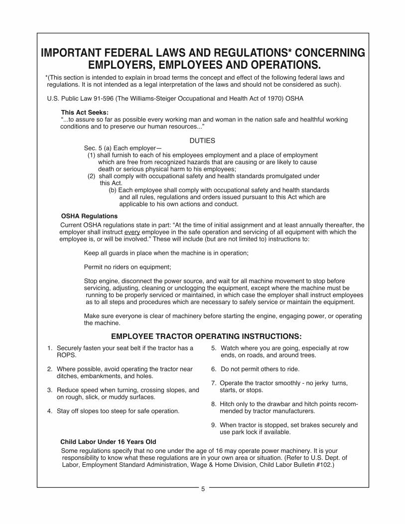
IMPORTANT FEDERAL LAWS AND REGULATIONS* CONCERNINGEMPLOYERS, EMPLOYEES AND OPERATIONS.
*(This section is intended to explain in broad terms the concept and effect of the following federal laws andregulations. It is not intended as a legal interpretation of the laws and should not be considered as such).
U.S. Public Law 91-596 (The Williams-Steiger Occupational and Health Act of 1970) OSHA
This Act Seeks:“...to assure so far as possible every working man and woman in the nation safe and healthful workingconditions and to preserve our human resources...”
DUTIESSec. 5 (a) Each employer—(1) shall furnish to each of his employees employment and a place of employment
which are free from recognized hazards that are causing or are likely to causedeath or serious physical harm to his employees;
(2) shall comply with occupational safety and health standards promulgated underthis Act.
(b) Each employee shall comply with occupational safety and health standardsand all rules, regulations and orders issued pursuant to this Act which areapplicable to his own actions and conduct.
OSHA RegulationsCurrent OSHA regulations state in part: “At the time of initial assignment and at least annually thereafter, theemployer shall instruct every employee in the safe operation and servicing of all equipment with which theemployee is, or will be involved.” These will include (but are not limited to) instructions to:
Keep all guards in place when the machine is in operation;
Permit no riders on equipment;
Stop engine, disconnect the power source, and wait for all machine movement to stop before servicing, adjusting, cleaning or unclogging the equipment, except where the machine must berunning to be properly serviced or maintained, in which case the employer shall instruct employeesas to all steps and procedures which are necessary to safely service or maintain the equipment.
Make sure everyone is clear of machinery before starting the engine, engaging power, or operating the machine.
Child Labor Under 16 Years OldSome regulations specify that no one under the age of 16 may operate power machinery. It is yourresponsibility to know what these regulations are in your own area or situation. (Refer to U.S. Dept. ofLabor, Employment Standard Administration, Wage & Home Division, Child Labor Bulletin #102.)
EMPLOYEE TRACTOR OPERATING INSTRUCTIONS:1. Securely fasten your seat belt if the tractor has a
ROPS.
2. Where possible, avoid operating the tractor near ditches, embankments, and holes.
3. Reduce speed when turning, crossing slopes, andon rough, slick, or muddy surfaces.
4. Stay off slopes too steep for safe operation.
5. Watch where you are going, especially at row ends, on roads, and around trees.
6. Do not permit others to ride.
7. Operate the tractor smoothly - no jerky turns, starts, or stops.
8. Hitch only to the drawbar and hitch points recom-mended by tractor manufacturers.
9. When tractor is stopped, set brakes securely and use park lock if available.
5

SECTION IINTRODUCTION AND DESCRIPTION
1-1 INTRODUCTIONWe are pleased to have you as a Bush Hog cus-tomer. Your Model 2315 Flex Wing Rotary Cutterhas been carefully designed to give maximum ser-vice with minimum down time. This manual is pro-vided to give you the necessary operating and main-tenance instructions for keeping your rotary cutter intop operating condition. Please read this manualthoroughly. Understand what each control is for andhow to use it. Observe all safety precautionsdecaled on the machine and noted throughout themanual for safe operation of implement. If anyassistance or additional information is needed, con-tact your authorized Bush Hog dealer.
NOTEAll references made in this manual to right, left, front,rear, top or bottom is as viewed facing the directionof forward travel with implement properly attached totractor.
1-2 DESCRIPTIONThe Model 2315 Rotary Cutter (Figure 1-1) consistsof a center unit with two variable position wingstogether having a cutting width of 15 feet (4.5m).Wing operating angles and machine cutting heightare independently controlled using hydraulic cylin-ders. A self-leveling linkage maintains a level cutterat all cutting heights. Power from the tractor PTO issplit at the center gearbox and supplied to each ofthe blade gearboxes. Each blade gearbox has two
free-swinging uplift blades designed for light mow-ing. Free-swinging blades reduce the shock ofimpact when a stationary object is hit. Slip clutchesare installed on each gearbox for additional protec-tion. Front and rear center discharge shields areincluded as standard equipment. (Note: Dealer orpurchaser may elect to delete the front shields attheir option.) Machine specifications are given inTable 1-1.
TABLE 1-1 SPECIFICATIONSLength . . . . . . . . . . . . . . . . . . . . . . . . . . . . . .183 in.Transport Width @ Tire in Transport . . . . . . .114 in.Transport Height . . . . . . . . . . . . . . . . . . . . . . . .81 in.Working Width . . . . . . . . . . . . . . .186 in. (472.4 cm)Cutting Height . . . . . . . . . . . .2-14 in. (5.1 - 35.6 cm)Cutting Capacity . . . . . . . . .Through 1.5 in. diameter
Varies according to cutting conditions
Blades . . . . . . . . .1/2 x 4 in. (12.7 x 101.6 mm) upliftBlade Overlap . . . . . . . . . . . . . . . . . .6 in. (15.2 cm)Blade Tip Speed . . . . .15,268 rpm @ 540 PTO rpmGearbox Horsepower . . . . . . . . . . . Center - 125 hp
Wing Gearbox - 80 hpMinimum Required Tractor Horsepower . . . . .50 hpMaximum Tractor Horsepower . . . . . . . . . . . .100 hpWorking Angles w/Driveline Engagement . . . .60° up
to 22° down
Wing Angles . . . . . . . . . . . . . . . .90° up to 22° downHitch . . . . . . . . . . . . . . . . . . . . .Clevis type standard
Clevis
Jackstand
U-Joint
Hose Holder Rod
Center Gearbox Shield
Wing Cylinder
Height Adjustment Cylinder
Axle
Axle Arm
Laminated Tire
Replaceable Wing Skid
Wing Gearbox
TongueHeight Adjustment
Driveline Retainer
Tongue
Discharge Shield(Chains)
Pillow BlockShield
Wing Transport Lock
Figure 1-1
6
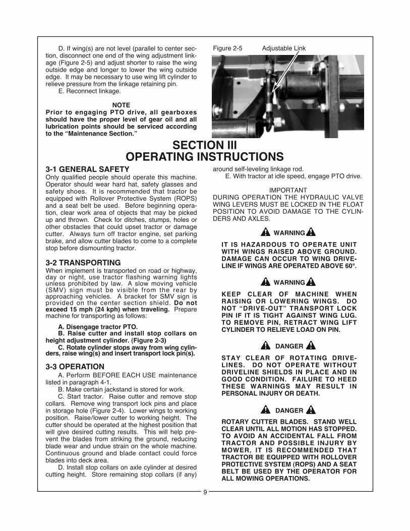
D. If wing(s) are not level (parallel to center sec-tion, disconnect one end of the wing adjustment link-age (Figure 2-5) and adjust shorter to raise the wingoutside edge and longer to lower the wing outsideedge. It may be necessary to use wing lift cylinder torelieve pressure from the linkage retaining pin.
E. Reconnect linkage.
NOTEPrior to engaging PTO drive, all gearboxesshould have the proper level of gear oil and alllubrication points should be serviced accordingto the “Maintenance Section.”
SECTION IIIOPERATING INSTRUCTIONS
3-1 GENERAL SAFETYOnly qualified people should operate this machine.Operator should wear hard hat, safety glasses andsafety shoes. It is recommended that tractor beequipped with Rollover Protective System (ROPS)and a seat belt be used. Before beginning opera-tion, clear work area of objects that may be pickedup and thrown. Check for ditches, stumps, holes orother obstacles that could upset tractor or damagecutter. Always turn off tractor engine, set parkingbrake, and allow cutter blades to come to a completestop before dismounting tractor.
3-2 TRANSPORTINGWhen implement is transported on road or highway,day or night, use tractor flashing warning lightsunless prohibited by law. A slow moving vehicle(SMV) sign must be visible from the rear byapproaching vehicles. A bracket for SMV sign isprovided on the center section shield. Do notexceed 15 mph (24 kph) when traveling. Preparemachine for transporting as follows:
A. Disengage tractor PTO.B. Raise cutter and install stop collars on
height adjustment cylinder. (Figure 2-3)C. Rotate cylinder stops away from wing cylin-
ders, raise wing(s) and insert transport lock pin(s).
3-3 OPERATIONA. Perform BEFORE EACH USE maintenance
listed in paragraph 4-1.B. Make certain jackstand is stored for work.C. Start tractor. Raise cutter and remove stop
collars. Remove wing transport lock pins and placein storage hole (Figure 2-4). Lower wings to workingposition. Raise/lower cutter to working height. Thecutter should be operated at the highest position thatwill give desired cutting results. This will help pre-vent the blades from striking the ground, reducingblade wear and undue strain on the whole machine.Continuous ground and blade contact could forceblades into deck area.
D. Install stop collars on axle cylinder at desiredcutting height. Store remaining stop collars (if any)
around self-leveling linkage rod.E. With tractor at idle speed, engage PTO drive.
IMPORTANTDURING OPERATION THE HYDRAULIC VALVEWING LEVERS MUST BE LOCKED IN THE FLOATPOSITION TO AVOID DAMAGE TO THE CYLIN-DERS AND AXLES.
IT IS HAZARDOUS TO OPERATE UNIT WITH WINGS RAISED ABOVE GROUND. DAMAGE CAN OCCUR TO WING DRIVE-LINE IF WINGS ARE OPERATED ABOVE 60°.
KEEP CLEAR OF MACHINE WHENRAISING OR LOWERING WINGS. DO NOT “DRIVE-OUT” TRANSPORT LOCK PIN IF IT IS TIGHT AGAINST WING LUG. TO REMOVE PIN, RETRACT WING LIFT CYLINDER TO RELIEVE LOAD ON PIN.
STAY CLEAR OF ROTATING DRIVE-LINES. DO NOT OPERATE WITHOUT DRIVELINE SHIELDS IN PLACE AND IN GOOD CONDITION. FAILURE TO HEED THESE WARNINGS MAY RESULT IN PERSONAL INJURY OR DEATH.
ROTARY CUTTER BLADES. STAND WELL CLEAR UNTIL ALL MOTION HAS STOPPED.TO AVOID AN ACCIDENTAL FALL FROM TRACTOR AND POSSIBLE INJURY BY MOWER, IT IS RECOMMENDED THAT TRACTOR BE EQUIPPED WITH ROLLOVERPROTECTIVE SYSTEM (ROPS) AND A SEATBELT BE USED BY THE OPERATOR FOR ALL MOWING OPERATIONS.
WARNING
WARNING
DANGER
DANGER
Figure 2-5 Adjustable Link
9
FAILURE TO MATCH VALVE TO TRAC-TOR HYDRAULIC SYSTEM BY USING INCORRECT PLUG WILL CAUSE DAM-AGE TO TRACTOR.
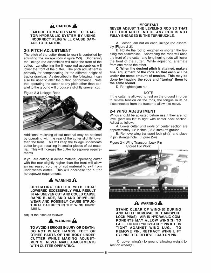
2-3 PITCH ADJUSTMENTThe pitch of the cutter (front to rear) is controlled byadjusting the linkage rods (Figure 2-3). Shorteningthe linkage rod assemblies will raise the front of thecutter. Lengthening the linkage rod assemblies willlower the front of the cutter. The pitch adjustment isprimarily for compensating for the different height oftractor drawbar. As described in the following, it canalso be used to alter the cutting performance. Notethat operating the cutter at any pitch other than par-allel to the ground will produce a slightly uneven cut.
Additional mulching of cut material may be attainedby operating with the rear of the cutter slightly lowerthan the front. This will keep the foliage underneathcutter longer, resulting in smaller pieces of cut mate-rial. This will increase the cutter horsepower require-ments.
If you are cutting in dense material, operating cutterwith the rear slightly higher than the front will allowan increased volume of cut material to exit fromunderneath cutter. This will decrease the cutterhorsepower requirements.
OPERATING CUTTER WITH REARLOWERED EXCESSIVELY WILL RESULT IN AN UNEVEN CUT AND COULD CAUSE RAPID BLADE, SKID AND DRIVELINEWEAR AND POSSIBLY CAUSE STRUC-TURAL FAILURES IN THE WING HINGEAREA.
Adjust the pitch as follows:
TO AVOID SERIOUS INJURY OR DEATH:DO NOT PLACE HANDS, FEET OR OTHER PARTS OF THE BODY UNDER CUTTER WHILE MAKING ADJUST-MENTS. NEVER MAKE ADJUSTMENTS WITH CUTTER OPERATING.
CAUTION
WARNING
WARNING
Figure 2-3 Linkage Rods
IMPORTANTNEVER ADJUST THE LEVELING ROD SO THATTHE THREADED END OF ANY ROD IS NOTFULLY ENGAGED IN THE TURNBUCKLE.
A. Loosen jam nut on each linkage rod assem-bly (Figure 2-3).
B. Rotate the rod to lengthen or shorten the lev-eling rod assemblies. Shortening the rods will raisethe front of the cutter and lengthening rods will lowerthe front of the cutter. While adjusting, alternatefrom one rod to the other.
C. When the desired pitch is attained, make afinal adjustment of the rods so that each will beunder the same amount of tension. This may bedone by tapping the rods and “tuning” them tothe same sound.
D. Re-tighten jam nut.
NOTEIf the cutter is allowed to rest on the ground in orderto relieve tension on the rods, the tongue must bedisconnected from the tractor to allow it to move.
2-4 WING ADJUSTMENTWings should be adjusted before use if they are notlevel (parallel) left to right with center deck section.Adjust as follows:
A. Lower cutter until skids on center section areapproximately 1-2 inches (25-51mm) off ground.
B. Remove wing transport lock pin(s) and placein pin storage hole. (Figure 2-4)
WARNING
STAND CLEAR OF WING(S) DURING AND AFTER REMOVAL OF TRANSPORT LOCK PIN(S). AIR IN HYDRAULIC COM-PONENTS MAY ALLOW WING(S) TO FALL. DO NOT “DRIVE-OUT” PIN IF IT IS TIGHT AGAINST WING LUG. TO REMOVE PIN, RETRACT WING LIFT CYLINDER TO RELIEVE LOAD ON PIN.
Figure 2-4 Wing Transport Lock PinStored For Work
C. Lower wing(s) to ground allowing weight torest on wheel(s).
8

D. If wing(s) are not level (parallel to center sec-tion, disconnect one end of the wing adjustment link-age (Figure 2-5) and adjust shorter to raise the wingoutside edge and longer to lower the wing outsideedge. It may be necessary to use wing lift cylinder torelieve pressure from the linkage retaining pin.
E. Reconnect linkage.
NOTEPrior to engaging PTO drive, all gearboxesshould have the proper level of gear oil and alllubrication points should be serviced accordingto the “Maintenance Section.”
SECTION IIIOPERATING INSTRUCTIONS
3-1 GENERAL SAFETYOnly qualified people should operate this machine.Operator should wear hard hat, safety glasses andsafety shoes. It is recommended that tractor beequipped with Rollover Protective System (ROPS)and a seat belt be used. Before beginning opera-tion, clear work area of objects that may be pickedup and thrown. Check for ditches, stumps, holes orother obstacles that could upset tractor or damagecutter. Always turn off tractor engine, set parkingbrake, and allow cutter blades to come to a completestop before dismounting tractor.
3-2 TRANSPORTINGWhen implement is transported on road or highway,day or night, use tractor flashing warning lightsunless prohibited by law. A slow moving vehicle(SMV) sign must be visible from the rear byapproaching vehicles. A bracket for SMV sign isprovided on the center section shield. Do notexceed 15 mph (24 kph) when traveling. Preparemachine for transporting as follows:
A. Disengage tractor PTO.B. Raise cutter and install stop collars on
height adjustment cylinder. (Figure 2-3)C. Rotate cylinder stops away from wing cylin-
ders, raise wing(s) and insert transport lock pin(s).
3-3 OPERATIONA. Perform BEFORE EACH USE maintenance
listed in paragraph 4-1.B. Make certain jackstand is stored for work.C. Start tractor. Raise cutter and remove stop
collars. Remove wing transport lock pins and placein storage hole (Figure 2-4). Lower wings to workingposition. Raise/lower cutter to working height. Thecutter should be operated at the highest position thatwill give desired cutting results. This will help pre-vent the blades from striking the ground, reducingblade wear and undue strain on the whole machine.Continuous ground and blade contact could forceblades into deck area.
D. Install stop collars on axle cylinder at desiredcutting height. Store remaining stop collars (if any)
around self-leveling linkage rod.E. With tractor at idle speed, engage PTO drive.
IMPORTANTDURING OPERATION THE HYDRAULIC VALVEWING LEVERS MUST BE LOCKED IN THE FLOATPOSITION TO AVOID DAMAGE TO THE CYLIN-DERS AND AXLES.
IT IS HAZARDOUS TO OPERATE UNIT WITH WINGS RAISED ABOVE GROUND. DAMAGE CAN OCCUR TO WING DRIVE-LINE IF WINGS ARE OPERATED ABOVE 60°.
KEEP CLEAR OF MACHINE WHENRAISING OR LOWERING WINGS. DO NOT “DRIVE-OUT” TRANSPORT LOCK PIN IF IT IS TIGHT AGAINST WING LUG. TO REMOVE PIN, RETRACT WING LIFT CYLINDER TO RELIEVE LOAD ON PIN.
STAY CLEAR OF ROTATING DRIVE-LINES. DO NOT OPERATE WITHOUT DRIVELINE SHIELDS IN PLACE AND IN GOOD CONDITION. FAILURE TO HEED THESE WARNINGS MAY RESULT IN PERSONAL INJURY OR DEATH.
ROTARY CUTTER BLADES. STAND WELL CLEAR UNTIL ALL MOTION HAS STOPPED.TO AVOID AN ACCIDENTAL FALL FROM TRACTOR AND POSSIBLE INJURY BY MOWER, IT IS RECOMMENDED THAT TRACTOR BE EQUIPPED WITH ROLLOVERPROTECTIVE SYSTEM (ROPS) AND A SEATBELT BE USED BY THE OPERATOR FOR ALL MOWING OPERATIONS.
WARNING
WARNING
DANGER
DANGER
Figure 2-5 Adjustable Link
9
F. Place tractor in gear and proceed forward.Advance tractor throttle to correct PTO speed forimplement (540 RPM). Tractor forward speedshould be controlled by gear selection, not enginespeed. For maximum cutting efficiency, forwardspeed should allow cutter to maintain a con-stant, maximum blade speed. Failure to maintainproper blade RPM will result in poor cutting perfor-mance and excessive blade and blade bolt wear. IfPTO drive is disengaged due to cutter stalling ortractor engine bogging, cutter must be raised tomaximum cutting height and tractor throttle reducedto idle before re-engaging. When in areas with tall,dense material, the front skids may push materialover and hold it down long enough to prevent bladesfrom cutting it. This will be evidenced by streaking inthe skid area. To alleviate this problem, remove thefront skids.
IMPORTANTDURING OPERATION, STOP AT REGULARINTERVALS AND CLEAN ACCUMULATEDDEBRIS FROM THE TOP OF CUTTER DECK,ESPECIALLY AROUND DRIVELINES AND GEAR-BOXES. THIS WILL HELP PREVENT MATERIALFROM CATCHING FIRE.
ALL ROTARY CUTTERS HAVE THE ABILITY TO DISCHARGE OBJECTS AT HIGH SPEEDS WHICH COULD RESULT IN SERIOUS INJURYTO BYSTANDERS OR PASSERS-BY.
THEREFORE, THIS CUTTER IS NOT TO BE OPERATED ALONG HIGHWAYS OR IN ANY AREA WHERE PEOPLE MAY BE PRESENT UNLESS ALL SIDES OF THE UNIT ARE ENCLOSED BY PERMANENT BANDS, SAFE-TY CHAINS, OR OTHER FACTORY APPROVED SAFETY SHIELDS THAT ARE IN GOOD REPAIR.
WARNING
SECTION IVMAINTENANCE
4-1 MAINTENANCE CHECK LISTPerform scheduled maintenance as outlined below.Lower machine to ground, turn off tractor and setparking brake before doing maintenance, inspec-tions, or work. Some checks may require raisingmachine off ground and supporting with blocks. Allbolts should be torqued as recommended in TorqueChart unless otherwise indicated.
THE CUTTER CAN FALL FROM HYDRAULIC SYSTEM FAILURE . TO AVOID SERIOUS INJURY OR DEATH, SECURELY SUPPORT CUTTER BEFORE WORKING UNDERNEATH.
BEFORE EACH USE
1. Make certain driveline shields are in place and ingood repair to minimize entanglement injuries to persons by rotating drivelines. Driveline shields should be chained for non-rotation.
2. Make certain deflector shields (chains, bands,etc.) are in good repair to minimize injuries to person by the discharge of high speed thrown objects.
3. Inspect blades for wear. Replace if necessary per paragraph 4-3. Always replace both blades on spindle with two blades equal inweight. Use only genuine Bush Hog replace-ment blades.
4. Check blade bolts for tightness.Tighten to 450 ft./lbs.
5. Check blades and spindles to be sure that no for-eign objects such as wire or steel strapping bands are wrapped around them.
6. Inspect hydraulic lines and fittings for wear orleaks. Repair or replace if needed.
WARNING
USE A PIECE OF CARDBOARD OR WOOD RATHER THAN HANDS AND WEAR EYE PROTECTION WHEN SEARCHING FORHYDRAULIC LEAKS. ESCAPING HYDRAULIC OIL UNDER PRESSURE CAN PENETRATE THE SKIN. IF OIL IS INJECTED INTO THE SKIN, IT MUST BE SURGICALLY REMOVED WITHIN A FEW HOURS BY A DOCTOR ORGANGRENE MAY RESULT.
7. Inspect wheel(s) for wear, damage or foreignobjects. Repair or replace if necessary.
8. Check tractor tire air pressure. Refer to tractoroperator’s manual.
9. Perform BEFORE EACH USE lubrication perparagraph 4-2.
10. During operation, listen for abnormal sounds which might indicate loose parts, damaged bear-ings or other damage.
11. Check tapered pin retaining each end of each driveline for tightness. Tighten nut to 30 ft./lbs. Use only genuine Bush Hog replacement parts.
AFTER EACH USE
1. Clean all debris from machine and affixed safetydecals. Replace any missing or illegible decals.
2. Inspect cutter for worn or damaged components. Repair or replace before next use. Any replace-ment components installed during repair shall include the components current safety decalsspecified by the manufacturer to be affixed to the component.
3. Store cutter in a dry place.
CAUTION
10

4-2 LUBRICATION (Figure 4-1)NOTE
The multi-purpose grease referenced in this sectionis an NLGI Grade 2 type grease.
BEFORE EACH USE
1. Driveline Universal Joints - Apply 2-3 shots of multi-purpose grease with grease gun.
2. Driveline Guard - Apply 2-3 shots of multi-purpose grease with grease gun to plastic fitting.
3. Wing Driveline - Unfold cutter, rotate inner and outer shields until holes align. Apply multi-purpose grease to grease fitting accessive through exposed hole.
4. Wing Gearboxes - Add EP80W-90 oil, if neces-sary, to bring oil level to check plug located on side of housing. Capacity is 1 quart (.9L)
5. Center Gearbox - Add EP80W-90 oil, if neces-sary, to bring oil level to correct level on dipstick. Capacity is 2.8 quarts (2.6L).
40 HOURS
6. Input Driveline - Disconnect driveline fromtractor. Separate driveline. Clean telescoping members every 40 hours and completely coat with grease.
7. Wing Turnbuckles - Apply multi-purpose grease slowly with grease gun.
8. Leveling Rod Links - Apply multi-purpose grease slowly with grease gun.
120 HOURS9. Wheel Bearings - Apply multi-purpose grease
slowly with grease gun until grease relieves around seal.
Figure 4-1 Lubrication Points
(2) Before Each Use
(1) Before Each Use
To Remove Yoke Shield:Turn slotted head 90° withscrewdriver, remove turn screwand slide cover back.
(4) Before Each Use
(3) Before Each Use
(6) 40 Hrs.
(8) 40 Hrs.
(7) 40 Hrs.
(9) 120 Hrs.
(5) Before Each Use
11

BU
SH H
OG
MO
DE
L2
315
FL
EX
-WIN
G R
OTA
RY
CU
TT
ER
1213
®

4-3 BLADE REPLACEMENTIt is not necessary to remove the complete bladeholder assembly to replace the blades. Blade boltsare accessible through a hole in the top of the cutterdeck. Always replace both blades on a spindleusing two blades having the same weight. Useonly genuine Bush Hog replacement blades.
A. Remove nuts from blade bolts. A blade nutsocket (Part No. 6432) can be bought at your BushHog dealer and used with an adjustable wrench (notsupplied) to remove blade nut. Blade nut can alsobe removed with a 1-11/16” socket.
B. Inspect blade bolt shoulder for wear. Replaceif necessary.
C. Assemble new blades to blade holder usingblade bolts, nuts and lockwashers. Refer to BLADEROTATION DIAGRAM for blade placement.Tighten nuts to 450 ft. / lbs. Strike blade bolthead with heavy hammer to seat, then retighten.
D. Check to be sure blades swing 360° freely. Ifblades will not swing freely, remove, locate problem,and repair. Operating cutter when blades will notswing freely will cause excessive vibration, damag-ing implement.
4-4 BLADE PAN REMOVALA. Blade pan can be removed by simply removing
the blades and blade bolts. Note: Wear heavygloves when handling blade pan due to possiblesharp edges.4-5 BLADE HOLDER ASSEMBLY
REMOVAL AND INSTALLATIONA. Remove cotter pin and blade holder assembly
retaining nut and washer. Retaining nut can beremoved or tightened with a 1-13/16” socket.
B. Wearing heavy gloves, grasp blade holder andpull off shaft. If stuck, align blade bolt with accesshole in top of cutter deck. Using hammer and apiece of pipe, strike blade bar. Repeat until bladeholder comes off. Care should be taken not to dam-age blade bolt threads.
TO INSTALL:A. Align the blade holder so the cotter pin hole is
positioned 90 degrees to the blade bar (for ease ofinstalling the cotter pin).
B. Place blade holder assembly, washer, andretaining nut on lower shaft. Torque nut to 450ft./lbs.
C. Install cotter pin. It may be necessary to tight-en nut slightly to install cotter pin.
BladeP/N 11170
BladeP/N 7556
BladeP/N 7555
BLADE ROTATION DIAGRAM
BladeP/N 7556
BladeP/N 11150
BladeP/N 7555
14
4-6 SLIP CLUTCH OPERATIONAL CHECK
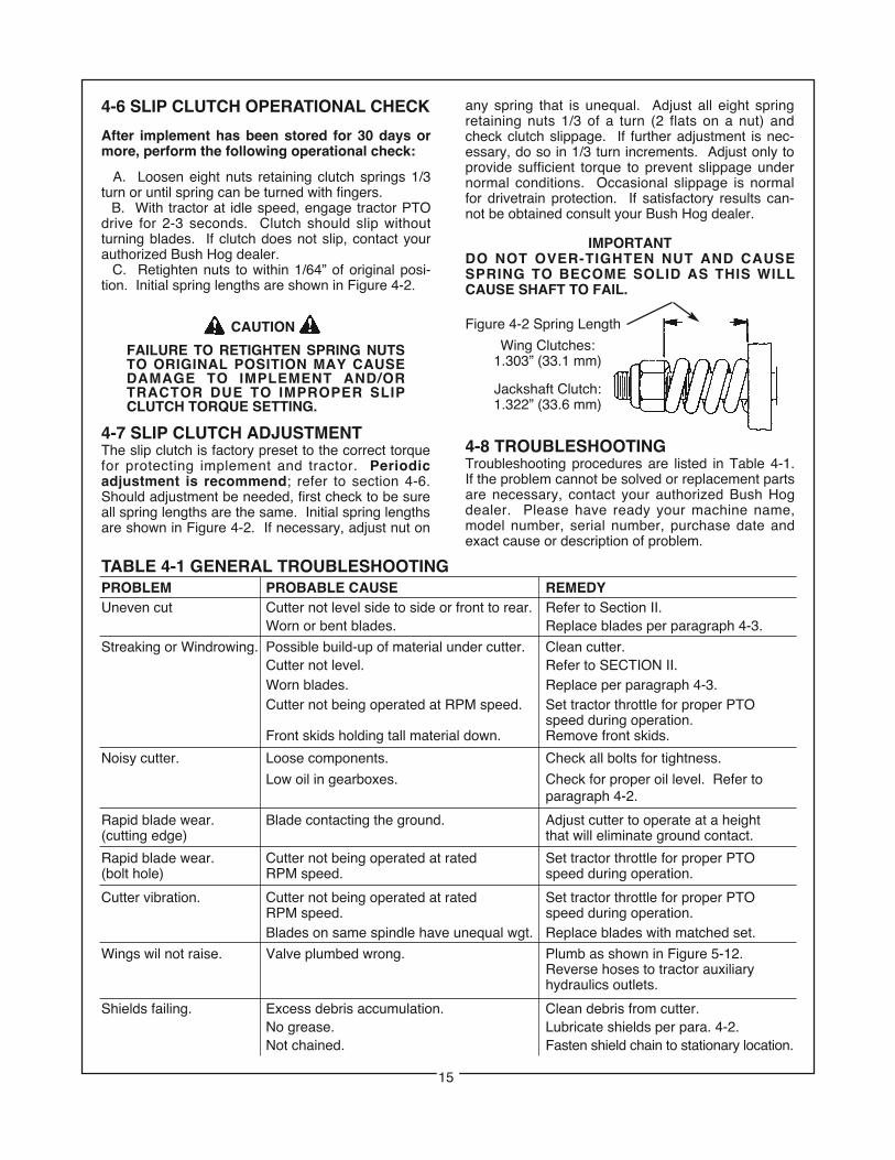
IMPORTANTDO NOT OVER-TIGHTEN NUT AND CAUSESPRING TO BECOME SOLID AS THIS WILLCAUSE SHAFT TO FAIL.
4-8 TROUBLESHOOTINGTroubleshooting procedures are listed in Table 4-1.If the problem cannot be solved or replacement partsare necessary, contact your authorized Bush Hogdealer. Please have ready your machine name,model number, serial number, purchase date andexact cause or description of problem.
Figure 4-2 Spring Length
Wing Clutches:1.303” (33.1 mm)
Jackshaft Clutch:1.322” (33.6 mm)
After implement has been stored for 30 days ormore, perform the following operational check:
A. Loosen eight nuts retaining clutch springs 1/3turn or until spring can be turned with fingers.
B. With tractor at idle speed, engage tractor PTOdrive for 2-3 seconds. Clutch should slip withoutturning blades. If clutch does not slip, contact yourauthorized Bush Hog dealer.
C. Retighten nuts to within 1/64” of original posi-tion. Initial spring lengths are shown in Figure 4-2.
CAUTION
FAILURE TO RETIGHTEN SPRING NUTS TO ORIGINAL POSITION MAY CAUSE DAMAGE TO IMPLEMENT AND/OR TRACTOR DUE TO IMPROPER SLIP CLUTCH TORQUE SETTING.
4-7 SLIP CLUTCH ADJUSTMENTThe slip clutch is factory preset to the correct torquefor protecting implement and tractor. Periodicadjustment is recommend; refer to section 4-6.Should adjustment be needed, first check to be sureall spring lengths are the same. Initial spring lengthsare shown in Figure 4-2. If necessary, adjust nut on
any spring that is unequal. Adjust all eight springretaining nuts 1/3 of a turn (2 flats on a nut) andcheck clutch slippage. If further adjustment is nec-essary, do so in 1/3 turn increments. Adjust only toprovide sufficient torque to prevent slippage undernormal conditions. Occasional slippage is normalfor drivetrain protection. If satisfactory results can-not be obtained consult your Bush Hog dealer.
TABLE 4-1 GENERAL TROUBLESHOOTINGPROBLEM PROBABLE CAUSE REMEDYUneven cut Cutter not level side to side or front to rear. Refer to Section II.
Worn or bent blades. Replace blades per paragraph 4-3.
Streaking or Windrowing. Possible build-up of material under cutter. Clean cutter.Cutter not level. Refer to SECTION II.Worn blades. Replace per paragraph 4-3.Cutter not being operated at RPM speed. Set tractor throttle for proper PTO
speed during operation.Front skids holding tall material down. Remove front skids.
Noisy cutter. Loose components. Check all bolts for tightness.
Low oil in gearboxes. Check for proper oil level. Refer toparagraph 4-2.
Rapid blade wear. Blade contacting the ground. Adjust cutter to operate at a height(cutting edge) that will eliminate ground contact.
Rapid blade wear. Cutter not being operated at rated Set tractor throttle for proper PTO(bolt hole) RPM speed. speed during operation.
Cutter vibration. Cutter not being operated at rated Set tractor throttle for proper PTORPM speed. speed during operation.Blades on same spindle have unequal wgt. Replace blades with matched set.
Wings wil not raise. Valve plumbed wrong. Plumb as shown in Figure 5-12.Reverse hoses to tractor auxiliaryhydraulics outlets.
Shields failing. Excess debris accumulation. Clean debris from cutter.No grease. Lubricate shields per para. 4-2.Not chained. Fasten shield chain to stationary location.
15
SECTION VASSEMBLY
THE FOLLOWING SAFETY PRECAUTIONS SHOULD BE THOROUGHLY UNDERSTOOD BEFORE ATTEMPTING MACHINE ASSEMBLY.
1. Wear personal protective equipment such as, but not limited to protection for eyes, ears, feet, hands, lungs and head when assembling the equipment. Do not wear loose clothing or jewelry that may catch on equipmentmoving parts.
2. Do not lift heavy parts or assemblies. Use crane, jack, tackle, fork trucks or other mechanical devices.
3. Select an area for assembly that is clean and free of any debris which might cause persons working on the assembly to trip.
4. Arrange parts to be assembled neatly in the work area and have tools or other mechanical assisting devices in easy reach.
5. Inspect all parts and assemblies thoroughly and remove any sharp edges, grease, oil or dirt which might cause pieces to slip when handling.
6. Preview the assembly instructions in your operator’s manual before proceeding further.
7. If the assembly instructions call for parts or assemblies to be blocked up, use only blocking material that is in good condition and is capable of handling the weight of the assembly to be blocked. Also, insure that the blocking material is on a clean, dry surface.
8. Never put hands or any other part of body under blocked up assemblies if at all possible.
9. Always wear goggles or safety glasses when hammering, grinding, or drilling metal parts.
10. If the assembly calls for welding or cutting, be sure that there are no flammable materials close at hand and that bystanders have taken necessary precautions.
AFTER COMPLETING ANY ASSEMBLY STEP, THOROUGHLY READ THE NEXT STEP IN THE ASSEMBLYINSTRUCTIONS BEFORE PROCEEDING WITH THAT STEP.
11. After completing assembly, thoroughly inspect the machine to be sure that all nuts, bolts, hydraulic fittings or any other fastened assemblies have been thoroughly tightened.
12. After completing assembly, be sure that all safety locking devices or guards are in place.
13. Before operating the machine, thoroughly read the operation section of this manual.
14. Before operating the machine, read the maintenance section of this manual to be sure that any parts requiring lubrication such as gearboxes are full to avoid any possible damage.
BEFORE OPERATING THE EQUIPMENT, IF YOU HAVE ANY QUESTIONS REGARDING THE PROPER ASSEMBLY OR OPERATION, CONTACT YOUR AUTHORIZED BUSH HOG DEALER OR REPRESENTATIVE.
CAUTION
16
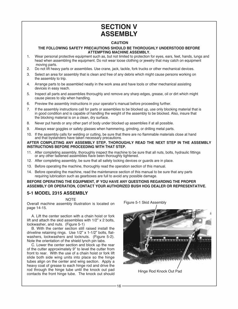
5-1 MODEL 2315 ASSEMBLYNOTE
Overall machine assembly illustration is located onpage 14-15.
A. Lift the center section with a chain hoist or forklift and attach the skid assemblies with 1/2” x 2 bolts,lockwasher, and nuts. (Figure 5-1)
B. With the center section still raised install thedriveline retaining rings. Use 1/2” x 1-1/2” bolts, flat-washers, lockwashers and locknuts. (Figure 5-2).Note the orientation of the shield lynch pin tabs.
C. Lower the center section and block up the rearof the cutter approximately 9” to level the cutter fromfront to rear. With the use of a chain hoist or fork liftslide both side wing units into place so the hingetubes align on the center and wing section. Apply aheavy coat of grease to each hinge rod and drive therod through the hinge tube until the knock out padcontacts the front hinge tube. The knock out should
Figure 5-1 Skid Assembly
Hinge Rod Knock Out Pad
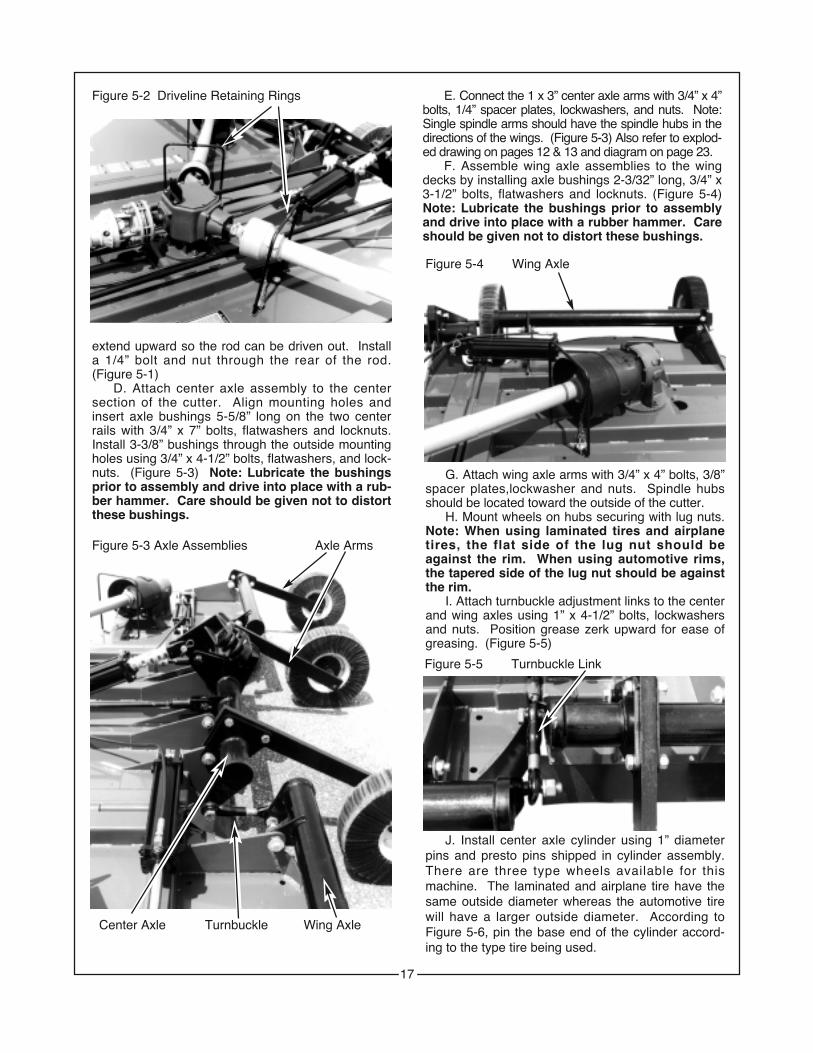
Figure 5-2 Driveline Retaining Rings
extend upward so the rod can be driven out. Installa 1/4” bolt and nut through the rear of the rod.(Figure 5-1)
D. Attach center axle assembly to the centersection of the cutter. Align mounting holes andinsert axle bushings 5-5/8” long on the two centerrails with 3/4” x 7” bolts, flatwashers and locknuts.Install 3-3/8” bushings through the outside mountingholes using 3/4” x 4-1/2” bolts, flatwashers, and lock-nuts. (Figure 5-3) Note: Lubricate the bushingsprior to assembly and drive into place with a rub-ber hammer. Care should be given not to distortthese bushings.
E. Connect the 1 x 3” center axle arms with 3/4” x 4”bolts, 1/4” spacer plates, lockwashers, and nuts. Note:Single spindle arms should have the spindle hubs in thedirections of the wings. (Figure 5-3) Also refer to explod-ed drawing on pages 12 & 13 and diagram on page 23.
F. Assemble wing axle assemblies to the wingdecks by installing axle bushings 2-3/32” long, 3/4” x3-1/2” bolts, flatwashers and locknuts. (Figure 5-4)Note: Lubricate the bushings prior to assemblyand drive into place with a rubber hammer. Careshould be given not to distort these bushings.
Figure 5-3 Axle Assemblies Axle Arms
Center Axle Turnbuckle Wing Axle
17
G. Attach wing axle arms with 3/4” x 4” bolts, 3/8”spacer plates,lockwasher and nuts. Spindle hubsshould be located toward the outside of the cutter.
H. Mount wheels on hubs securing with lug nuts.Note: When using laminated tires and airplanetires, the flat side of the lug nut should beagainst the rim. When using automotive rims,the tapered side of the lug nut should be againstthe rim.
I. Attach turnbuckle adjustment links to the centerand wing axles using 1” x 4-1/2” bolts, lockwashersand nuts. Position grease zerk upward for ease ofgreasing. (Figure 5-5)
J. Install center axle cylinder using 1” diameterpins and presto pins shipped in cylinder assembly.There are three type wheels available for thismachine. The laminated and airplane tire have thesame outside diameter whereas the automotive tirewill have a larger outside diameter. According toFigure 5-6, pin the base end of the cylinder accord-ing to the type tire being used.
Figure 5-4 Wing Axle
Figure 5-5 Turnbuckle Link

FIGURE 5-6 Cylinder Lug Mounting Locations
Top Hole- Bottom Hole-Automotive Tires Laminated or Airplane Tire
AxleCylinder
K. Bolt tongue to center section using 1” x 5-1/2”bolts, locknuts, and 3-17/32” bushing. (Figure 5-7)
L. Pin jackstand to tongue.M. Pin the slotted casting end of the leveling rods
assemblies to the tongue using pin, flatwasher, andcotter pins shipped with assembly. (Position forgreasing.) It may be necessary to raise the tongueslightly for the attachment of the leveling rod.Connect the opposite end to the center axle weld-ment using the pin and cotter pins shipped in the lev-eling rod assembly. (Figure 5-8)
N. Slide pillow block bearing onto jackshaft until itis against shoulder. Note: Collar on bearingshould be toward cutter. Slide lock collar up tobearing and turn in the direction of rotation until it
Figure 5-7 Tongue Center Section Lugs
Figure 5-8 Leveling Rod Non-Slotted Casting
slips over the inner ring extension. Turn collarquickly in the direction of rotation (approximately 1/4turn) to tighten. (Figure 5-9)
O. Place punch in blind hole in collar. (Figure 5-10) Strike punch sharply with hammer in the direc-tion of rotation to lock collar tightly against inner ringextension. Tighten set screw to 20 ft/lbs.
P. Bolt pillow block strap weldment to tongue with5/8” x 1-1/2” fasteners and locknuts. Figure 5-11.Tighten locknuts but allow movement of strap weld-ment.
Input Shaft Jackshaft
Q. Fasten jackshaft to center gearbox andtighten tapered pin nut to 30 ft./lbs. Attach pillowblock bearing to bearing mount using a 1/2” x 5-1/2”bolt and locknut. (Figure 5-12) Tighten locknut butallow motion of pillow block housing.
Figure 5-9Pillow Block Bearing
Jackshaft
Inner RingExtension
Lock Collar
Figure 5-10Punch
Lock Collar
Figure 5-11 Hose Holder Rod Center ShieldBearing Shield Jackshaft
R. Attach bearing shield (beveled end forward) totop of pillow block bearing using 3/8” x 3/4” bolts andlockwashers. (Figure 5-11)
S. Attach input driveline to jackshaft and tight-
18

en tapered pin nut to 30 ft./lbs. (Figure 5-11)T. Attach hose holder rod to tongue using 5/8” x
2” bolt, nut, flatwasher and lockwasher. (Figure 5-11)
U. Install plastic clutch shield on wing gearboxesusing four 8 mm x 15 mm bolts and flatwashers pershield. (Figure 5-12)
V. Install wing drivelines, attaching clutch towing gearboxes. Secure driveline with taperedpin, lockwasher and nut. Tighten nut to 30ft./lbs. Pull on each driveline section to make cer-tain it is securely attached. (Figure 5-12)
W. Install wing lift cylinders with the rod end con-nected to the wing lug. It will be necessary toremove port plugs to extend cylinder. Pin the baseend of the cylinder to the cylinder lug on the centersection using the 1” pin and presto pins shipped withthe cylinder. Place the rod end of the cylinderbetween the two lugs on the wing section. Place thecylinder stop between the clevis ends of the cylinderrod. Locate the over center latch to the rear of thelug as shown and fasten with 1” x 6-1/4” pin, flat-washer and 1/4” roll pins. (Figure 5-13) Note: Aflatwasher is required on both ends of the pinbetween the roll pin and the slotted cylinderlugs. If this is not done the pin can work free ofthe cylinder lug.
Figure 5-12 Wing Driveline Clutch Shield
Shield Chain Retaining Ring
X. Plumb hydraulic cylinders as shown. (Figures5-14, a & b) (Hydraulic hoses are supplied forattachment to three tractor remotes.) Plugs are sup-plied to adapt value for either an open or closed cen-
Figure 5-13 Over Center Latch Cylinder Stop
Wing Lugs
Wing Cyl.Rod
19
ter tractor hydraulic system. Consult your tractordealer to determine which type system your tractorhas. Use tie straps to secure hydraulic hoses to lev-eling rod.
FAILURE TO MATCH VALVE TO TRACTOR HYDRAULIC SYSTEM BY USING INCOR-RECT PLUG WILL CAUSE DAMAGE TO TRACTOR.
Y. Fill each wing gearbox with EP80W-90 gearoil to check plug on rear of gearbox. Allow timefor oil to seep through bearings into lower hous-ing. Replace temporary plug with vent plug sup-plied in operator’s manual package.
Z. Fill the center gearbox with EP80W-90 gearoil to the level mark as denoted on the vent plugdip stick shipped in the operator’s manual pack-age. Allow time for oil to seep through bearingsinto lower housing. Replace the temporary plugwith this vent plug dip stick.
AA. Attach center shield mounting bracket withtwo 8 mm x 20 mm bolts and flatwashers. Discardthe two fasteners removed from the gearbox. Notethe position of the shield mounting bracket. (Figure5-15)
CAUTION
BB. Secure the center shield to the mounts withthree lynch pins. (Figure 5-15)
Figure 5-15 Center Shield Mounting Bracket
CC. Attach all driveline shield chains to keepshields from turning. (Figure 5-15)
DD. On each clutch, loosen eight nuts retain-ing clutch springs 1/3 turn or until spring can beturned with fingers.
EE. With tractor at idle speed, engage tractorPTO drive 2-3 seconds. Each clutch should slipwithout turning blades.
FF. Retighten nuts to within 1/64” of originalposition. Initial spring length for the wing clutchis 1.303” and the initial spring length for the jack-shaft clutch is 1.322”.
FAILURE TO RETIGHTEN NUTS TOORIGINAL POSITION MAY CAUSEDAMAGE TO IMPLEMENT AND/OR TRAC-TOR DUE TO IMPROPER SLIP CLUTCH TORQUE SETTING.
CAUTION

GG. Note: Refer back to Section 2-1G priorto folding the wings with the tractor hydraulics.Fold wings into the transport position and installtransport lock pins and presto pin.
HH. Fasten the wing driveline retaining rings tothe wings sections using 1/2” x 1-1/2” bolts, flat-washers, lockwashers and nuts. (Figure 5-12)
II. With the wings folded raise the center sectionand install stop collars on height adjustment cylinderto retain in this position.
JJ. Attach the rear belting or rear chains with3/8” x 1” bolts, flatwashers, lockwashers and nuts.(Figure 5-16)
FRONT BELTINGA. Compare each front belting (Figure 5-16) to
determine location for installation.B. Align holes in belting with holes on the front lip
of the cutter. Attach with 3/8” x 1” bolts, flatwashersand locknuts.
FRONT CHAINA. Align holes in chain assembly with the holes in
the front lip of the cutter. Attach with 3/8” x 1-1/4”bolts, flatwasher, lockwashers and locknuts. (Figure5-16)
B. Install three links of chain between the fronthitch lugs by installing 3/8” x 5” bolt, chain spacers,and locknut.
NOTE:FLEXIBLE BANDS OR CHAINSINSTALL IN THE SAME MANNEREXCEPT FOR THE THREE PIECECHAIN SECTIONS AT THE FRONTCENTER OF THE MACHINE.
Figure 5-16 Flexible Band / Chain Installation
SAFETY TOW CHAINA. Securely attach tow chain to cutter by looping
hook end of chain around one side member oftongue and back through large link on opposite endof chain. (Figure 5-17)
B. Before use, attach loose end of chain to towingvehicle attaching point such as drawbar or bumper,etc. Fasten chain back to itself with hook latch.
Figure 5-17 Safety Tow Chain
Large Link
Spring LoadedHook Latch
Chain
20

3/4”
SA
E t
o 9
/16”
JIC
or
1/2”
NP
T t
o 9
/16”
JIC
Wh
en u
sin
g t
ract
or
hyd
rau
lics
Fig
ure
5-14
(a)
2315
PL
UM
BIN
G D
IAG
RA
M(U
SIN
G T
RA
CT
OR
HY
DR
AU
LIC
S)
21
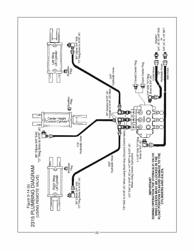
Fig
ure
5-14
(b)
2315
PLU
MB
ING
DIA
GR
AM
(US
ING
RE
MO
TE
VA
LVE
)
22

23
AXLE ARM ASSEMBLYLOCATIONS OF ARMS AND SPACER PLATES TO AXLE LUGS
3/8” Spacer
Left Wing Lug
1/4” Spacer
Center Axle Lugs(Left Side)
1/4” Spacer
Center Axle Lugs(Right Side)
3/8” SpacerRight Wing Lug
NOTE:The spacing betweenmounting holes in thewing axle arms is 6 - 7/16”.
The spacing betweenmounting holes in thecenter axle arms is 6”.
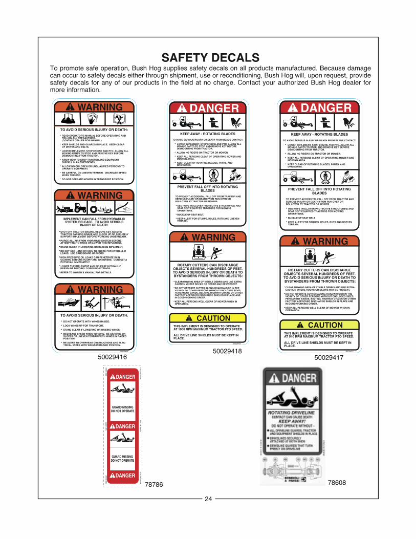
SAFETY DECALSTo promote safe operation, Bush Hog supplies safety decals on all products manufactured. Because damagecan occur to safety decals either through shipment, use or reconditioning, Bush Hog will, upon request, providesafety decals for any of our products in the field at no charge. Contact your authorized Bush Hog dealer formore information.
24
TO AVOID SERIOUS INJURY OR DEATH:
•N READ OPERATOR'S MANUAL BEFORE NOPERATING AND N FOLLOW ALL PRECAUTIONS.N (CONTACT DEALER FOR MANUAL)
•N KEEP SHIELDS AND GUARDS IN PLACE. NKEEP CLEAR N OF DRIVES AND BELTS.
•N LOWER IMPLEMENT, STOP ENGINE AND PTO, ALLOW ALL N MOVING PARTS TO STOP, AND NREMOVE KEY BEFORE N DISMOUNTING FROM TRACTOR.
•N KNOW HOW TO STOP TRACTOR AND NEQUIPMENT N QUICKLY IN AN EMERGENCY.
•N ALLOW NO CHILDREN OR UNQUALIFIED NPERSONS TON OPERATE EQUIPMENT.
•N BE CAREFUL ON UNEVEN TERRAIN. NDECREASE SPEEDN WHEN TURNING.
•N DO NOT OPERATE MOWER IN TRANSPORT NPOSITION.
WARNING
WARNING
IMPLEMENT CAN FALL FROM HYDRAULICSYSTEM RELEASE. TO AVOID SERIOUS
INJURY OR DEATH:
•NSHUT OFF TRACTOR ENGINE, REMOVE KEY, SECURE N TRACTORNPARKING BRAKE AND BLOCK UP OR SECURELYN SUPPORT IMPLEMENT BEFORE WORKING UNDERNEATH.
•NPURGE ALL AIR FROM HYDRAULIC SYSTEM BEFOREN ATTEMPTING TO RAISE OR LOWER THIS IMPLEMENT.
•NSTAND CLEAR IF LOWERING OR RAISING IMPLEMENT.
•NDO NOT USE HAND OR SKIN TO CHECK FOR HYDRAULICN LEAKS. USE CARDBOARD OR WOOD.
•NHIGH PRESSURE OIL LEAKS CAN PENETRATE SKIN N CAUSING SERIOUS INJURY AND GANGRENE. CONSULT A N PHYSICIAN IMMEDIATELY.
• LOWER THE IMPLEMENT AND RELEASE HYDRAULICN PRESSURE BEFORE LOOSENING FITTINGS.
•NREFER TO OWNER'S MANUAL FOR DETAILS.
TO AVOID SERIOUS INJURY OR DEATH:
•N DO NOT OPERATE WITH WINGS RAISED.
•N LOCK WINGS UP FOR TRANSPORT.
•N STAND CLEAR IF LOWERING OR RAISING WINGS.
•N DECREASE SPEED WHEN TURNING. BE CAREFUL ONN SLOPES OR UNEVEN TERRAIN WITH WINGS IN RAISED N POSITION.
•N BE ALERT TO OVERHEAD OBSTRUCTIONS AND ELEC-N TRICAL WIRES WITH WINGS IN RAISED POSITION.
WARNING
50029416
50029416 50029417
78786 78608
ROTARY CUTTERS CAN DISCHARGEOBJECTS SEVERAL HUNDREDS OF FEET.TO AVOID SERIOUS INJURY OR DEATH TO BYSTANDERS FROM THROWN OBJECTS:
•NCLEAR MOWING AREA OF VISIBLE DEBRIS AND USE EXTRAN CAUTION WHERE ROCKS OR DEBRIS MAY BE PRESENT.
•NDO NOT OPERATE CUTTER ALONG ROADWAYSNOR IN THE N VICINITY OF OTHER PERSONS WITHOUT ENCLOSED SIDES,N PERMANENT BANDS, BELTING, HIGHWAY CHAINS OR OTHERN FACTORY APPROVED DISCHARGE SHIELDS IN PLACE ANDN IN GOOD WORKING ORDER.
•NKEEP ALL PERSONS WELL CLEAR OF MOWER WHEN IN N OPERATION.
WARNING
KEEP AWAY - ROTATING BLADES
TO AVOID SERIOUS INJURY OR DEATH FROM BLADE CONTACT:
•N LOWER IMPLEMENT, STOP ENGINE AND PTO, ALLOW ALLN MOVING PARTS TO STOP, AND REMOVE KEY BEFORE N DISMOUNTING FROM TRACTOR.
• ALLOW NO RIDERS ON TRACTOR OR MOWER.
•N KEEP ALL PERSONS CLEAR OF OPERATING MOWER ANDN MOWING AREA.
•N KEEP CLEAR OF ROTATING BLADES, PARTS, AND N DRIVELINES.
PREVENT FALL OFF INTO ROTATINGBLADES
N TO PREVENT ACCIDENTAL FALL OFF FROM TRACTOR AND N SERIOUS INJURY OR DEATH FROM RUN OVER OR NN ROLLOVER BY TRACTOR OR MOWER:
N •NUSE ROPS (ROLLOVER PROTECTIVE STRUCTURES) AND NN SEAT BELT EQUIPPED TRACTORS FOR MOWING NN OPERATIONS.
N •NBUCKLE UP SEAT BELT.
N •NKEEP ALERT FOR STUMPS, HOLES, RUTS AND UNEVEN NN TERRAIN.
DANGER
THIS IMPLEMENT IS DESIGNED TO OPERATEAT 1000 RPM MAXIMUM TRACTOR PTO SPEED.
ALL DRIVE LINE SHIELDS MUST BE KEPT INPLACE.
CAUTION
50029418
50029418

TORQUE SPECIFICATIONSProper toque for American fasteners used on Bush Hog equipment.
Recommended Torque in Foot Pounds (Newton Meters).*
BOLT DIAMETERWRENCH (IN.) “B” AND SAE SAE SAE
SIZE (IN.) “A” THREAD SIZE GRADE 2 GRADE 5 GRADE 8
7/16 1/4 - 2O UNC 6 (7) 8 (11) 12 (16)
7/16 1/4 - 28 UNF 6 (8) 10 (13) 14 (18)
1/2 5/16 - 18 UNC 11 (15) 17 (23) 25 (33)
1/2 5/16 - 24 UNF 13 (17) 19 (26) 27 (37)
9/16 3/8 - 16 UNC 20 (27) 31 (42) 44 (60)
9/16 3/8 - 24 UNF 23 (31) 35 (47) 49 (66)
5/8 7/16 - 14 UNC 32 (43) 49 (66) 70 (95)
5/8 7/16 - 20 UNF 36 (49) 55 (75) 78 (106)
3/4 1/2 - 13 UNC 49 (66) 76 (103) 106 (144)
3/4 1/2 - 20 UNF 55 (75) 85 (115) 120 (163)
7/8 9/16 - 12 UNC 70 (95) 109 (148) 153 (207)
7/8 9/16 - 18 UNF 79 (107) 122 (165) 172 (233)
15/16 5/8 - 11 UNC 97 (131) 150 (203) 212 (287)
15/16 5/8 - 18 UNF 110 (149) 170 (230) 240 (325)
1-1/8 3/4 - 10 UNC 144 (195) 266 (360) 376 (509)
1-1/8 3/4 - 16 UNF 192 (260) 297 (402) 420 (569)
1-5/16 7/8 - 9 UNC 166 (225) 430 (583) 606 (821)
1-5/16 7/8 - 14 UNF 184 (249) 474 (642) 668 (905)
1-1/2 1 - 8 UNC 250 (339) 644 (873) 909 (1232)
1-1/2 1 - 12 UNF 274 (371) 705 (955) 995 (1348)
1-1/2 1 - 14 UNF 280 (379) 721 (977) 1019 (1381)
1-11/16 1-1/8 - 7 UNC 354 (480) 795 (1077) 1288(1745)
1-11/16 1-1/8 - 12 UNF 397 (538) 890 (1206) 1444 (1957)
1-7/8 1-1/4 - 7 UNC 500 (678) 1120 (1518) 1817 (2462)
1-7/8 1-1/4 - 12 UNF 553 (749) 1241 (1682) 2013 (2728)
2-1/16 1-3/8 - 6 UNC 655 (887) 1470 (1992) 2382 (3228)
2-1/16 1-3/8 - 12 UNF 746 (1011) 1672 (2266) 2712 (3675)
2-1/4 1-1/2 - 6 UNC 870 (1179) 1950 (2642) 3161 (4283)
2-1/4 1-1/2 - 12 UNF 979 (1327) 2194 (2973) 3557 (4820)
Proper torque for metric fasteners used on Bush Hog equpment.Recommended torque in foot pounds (newton Meters).*
WRENCH BOLTSIZE DIA. ASTM ASTM ASTM ASTM
(mm) “A” (mm) “B” 4.6 8.8 9.8 10.9
8 5 1.8 (2.4) 5.1 (6.9) 6.5 (8.8)
10 6 3 (4) 8.7 (12) 11.1 (15)
13 8 7.3 (10) 21.1 (29) 27 (37)
16 10 14.5 (20) 42 (57) 53 (72)
18 12 25 (34) 74 (100) 73 (99) 93 (126)
21 14 40 (54) 118 (160) 116 (157) 148 (201)
24 16 62 (84) 167 (226) 181 (245) 230 (312)
30 20 122 (165) 325 (440) 449 (608)
33 22 443 (600) 611 (828)
36 24 211 (286) 563 (763) 778 (1054)
41 27 821 (1112) 1138 (1542)
46 30 418 (566) 1119 (1516) 1547 (2096)
*Use 75% of the specified torque value for platedfasteners. Use 85% of the specificed torquevalues for lubricated fasteners.
Numbers appearing on bolt headsindicate ASTM class.
METRIC
AMERICANBolt Head Markings
WrenchSize “A”
Bolt
Diameter “B”
SAE Grade 8(6 Dashes)
SAE Grade 2(No Dashes)
SAE Grade 5(3 Dashes)
WrenchSize “A” 8.8
Bolt
Diameter “B”
25

BUSH HOG, L.L.C.
®
P.O. Box 1039 � Selma, AL 36702-1039Telephone (334) 874-2700 � www.bushhog.com