Embed Size (px)
Citation preview

ASSEMBLY ● OPERATION ● MAINTENANCE1006 $4.00 50054971
Operator’s Manual
PZ & CZ ZERO TURN MOWER
MAX VACGRASS COLLECTION SYSTEM
Models GC-350 &GC-350CZ

CONGRATULATIONS!You have invested in the best implement of its type on the market today.
The care you give your Bush Hog implement will greatly determine your satisfactionwith its performance and its service life. We urge a careful study of this manual to provideyou with a thorough understanding of your new implement before operating, as well assuggestions for operation and maintenance.
If your manual should become lost or destroyed, Bush Hog will be glad to provide you witha new copy. Order from Bush Hog, P. O. Box 1039, Selma, Alabama 36702-1039. Most of ourmanuals can also be downloaded from our website at www.bushhog.com.
As an authorized Bush Hog dealer, we stock genuine Bush Hog parts which aremanufactured with the same precision and skill as our original equipment. Our trainedservice personnel are well informed on methods required to service Bush Hog equipment,and are ready and able to help you.
Should you require additional information or assistance, please contact us.
YOUR AUTHORIZEDBUSH HOG DEALER
BECAUSE BUSH HOG MAINTAINS AN ONGOINGPROGRAM OF PRODUCT IMPROVEMENT, WE RESERVE THE RIGHT TO MAKE IMPROVEMENTS IN DESIGN OR CHANGES IN SPECIFICATIONS WITH-OUT INCURRING ANY OBLIGATION TO INSTALL THEM ON UNITS PREVIOUSLY SOLD.
BECAUSE OF THE POSSIBILITY THAT SOMEPHOTOGRAPHS IN THIS MANUAL WERE TAKEN OF PROTOTYPE MODELS, PRODUCTION MODELS MAY VARY IN SOME DETAIL. IN ADDITION, SOMEPHOTOGRAPHS MAY SHOW SHIELDS REMOVED FOR PURPOSES OF CLARITY. NEVER OPERATETHIS IMPLEMENT WITHOUT ALL SHIELDS IN PLACE.

PZ & CZ ZERO TURN MOWER
GRASS CATCHERTABLE OF CONTENTS
SECTION PAGEWarranty . . . . . . . . . . . . . . . . . . . . . . . . . . . . . 2
Federal Laws and Regulations . . . . . . . . . . . . 3
Safety Alert Symbols. . . . . . . . . . . . . . . . . . . . 4
I INTRODUCTION AND DESCRIPTION . . . . . 51-1 Introduction . . . . . . . . . . . . . . . . . . . . . . . . 51-2 Description . . . . . . . . . . . . . . . . . . . . . . . . 5
II PREPARATION FOR USE . . . . . . . . . . . . . . . 5
2-1 Modification Of ZT. . . . . . . . . . . . . . . . . . . 5
2-2 Attaching Frame Mount Brackets . . . . . . . 6
2-3 Belt Installation . . . . . . . . . . . . . . . . . . . . . 6
2-4 Cam Assembly Adjustment. . . . . . . . . . . . 72-5 Attachemnt Of Upper Frame. . . . . . . . . . . 7
Assembly To The Lower Frame2-6 Attachment Of Top Assembly To The. . . . 7
Upper Frame Assembly2-7 Attachment Of The Boot To . . . . . . . . . . . 7
The Mower Deck2-8 Adjustment Of The Lengths Of Hoses . . . 8
SECTION PAGE2-9 Attachment of The Upper Hose . . . . . . . . . . 82-10 Attachment Of The Upper Hose To. . . . . . . . 8
The Lower Cone2-11 Attachment Of The Lower Hose To . . . . . . 8
The Boot2-12 Front Weight Assembly . . . . . . . . . . . . . . . 82-13 Installation/Removal Of Collection Bags . . 8
III OPERATING INSTRUCTIONS . . . . . . . . . . . . 103-1 General Safety . . . . . . . . . . . . . . . . . . . . . . 103-2 Operation & Tips On Mowing . . . . . . . . . . . 103-3 Disengagement Of The Blower . . . . . . . . . 10
IV MAINTENANCE . . . . . . . . . . . . . . . . . . . . . . . . 104-1 Maintenance Checklist . . . . . . . . . . . . . . . . . . . 10
4-2 Lubrication . . . . . . . . . . . . . . . . . . . . . . . . . . . . . 11
Safety Decals . . . . . . . . . . . . . . . . . . . . . . . . . . . 12
Torque Specifications . . . . . . . . . . . . . . . . . . . . 13
1
RETAIL CUSTOMER’S RESPONSIBILITYUNDER THE BUSH HOG WARRANTY
It is the Retail Customer and/or Operator’s responsibility to read the Operator’s Manual, tooperate, lubricate, maintain and store the product in accordance with all instructions andsafety procedures. Failure of the operator to read the Operator’s Manual is a misuse of thisequipment.
It is the Retail Customer and/or Operator’s responsibility to inspect the product and to haveany part(s) repaired or replaced when continued operation would cause damage or exces-sive wear to other parts or cause a safety hazard.
It is the Retail Customer’s responsibility to deliver the product to the authorized Bush HogDealer, from whom he purchased it, for service or replacement of defective parts which arecovered by warranty. Repairs to be submitted for warranty consideration must be made with-in forty-five (45) days of failure.
It is the Retail Customer’s responsibility for any cost incurred by the Dealer for traveling to orhauling of the product for the purpose of performing a warranty obligation or inspection.

LIMITED WARRANTY✯✯✯✯✯✯✯✯✯✯✯✯✯✯✯✯✯✯✯✯✯✯✯✯✯✯✯✯✯✯✯
Bush Hog warrants to the original purchaser of any new Bush Hog equipment, purchased from anauthorized Bush Hog dealer, that the equipment be free from defects in material and workmanship for a periodof one (1) year from date of retail sale. The obligation of Bush Hog to the purchaser under this warranty is limit-ed to the repair or replacement of defective parts.
Replacement or repair parts installed in the equipment covered by this limited warranty are warrantedfor ninety (90) days from the date of purchase of such part or to the expiration of the applicable new equip-ment warranty period, whichever occurs later. Warranted parts shall be provided at no cost to the user at anauthorized Bush Hog dealer during regular working hours. Bush Hog reserves the right to inspect any equip-ment or parts which are claimed to have been defective in material or workmanship.
DISCLAIMER OF IMPLIED WARRANTIES & CONSEQUENTIAL DAMAGES
Bush Hog’s obligation under this limited warranty, to the extent allowed by law, is in lieu of all war-ranties, implied or expressed, INCLUDING IMPLIED WARRANTIES OF MERCHANTABILITY AND FITNESSFOR A PARTICULAR PURPOSE and any liability for incidental and consequential damages with respect tothe sale or use of the items warranted. Such incidental and consequential damages shall include but not belimited to: transportation charges other than normal freight charges; cost of installation other than costapproved by Bush Hog; duty; taxes; charges for normal service or adjustment; loss of crops or any other loss ofincome; rental of substitute equipment, expenses due to loss, damage, detention or delay in the delivery ofequipment or parts resulting from acts beyond the control of Bush Hog.
THIS LIMITED WARRANTY SHALL NOT APPLY:
1. To vendor items which carry their own warranties, such as engines, tires, and tubes.
2. If the unit has been subjected to misapplication, abuse, misuse, negligence, fire or other accident.
3. If parts not made or supplied by Bush Hog have been used in connection with the unit, if, in the sole judge-ment of Bush Hog such use affects its performance, stability or reliability.
4. If the unit has been altered or repaired outside of an authorized Bush Hog dealership in a mannerwhich, in the sole judgement of Bush Hog, affects its performance, stability or reliability.
5. To normal maintenance service and normal replacement items such as gearbox lubricant, hydraulic fluid, worn blades, or to normal deterioration of such things as belts and exterior finish due to use or exposure.
6. To expendable or wear items such as teeth, chains, sprockets, belts, springs and any other items that in thecompany’s sole judgement is a wear item.
NO EMPLOYEE OR REPRESENTATIVE OF BUSH HOG IS AUTHORIZED TO CHANGE THIS LIM-ITED WARRANTY IN ANY WAY OR GRANT ANY OTHER WARRANTY UNLESS SUCH CHANGE IS MADE IN WRITING AND SIGNED BY BUSH HOG’S SERVICE MANAGER, POST OFFICE BOX 1039, SELMA,ALABAMA 36702-1039.
✯✯✯✯✯✯✯✯✯✯✯✯✯✯✯✯✯✯✯✯✯✯✯✯✯✯✯✯✯✯✯Record the model number, serial number and datepurchased. This information will be helpful to yourdealer if parts or service are required.MAKE CERTAIN THE WARRANTY REGISTRATIONCARD HAS BEEN FILED WITH BUSH/SELMA, ALABAMA
MODEL NUMBER
SERIAL NUMBER
DATE OF RETAIL SALE
2

IMPORTANT FEDERAL LAWS AND REGULATIONS* CONCERNINGEMPLOYERS, EMPLOYEES AND OPERATIONS.
*(This section is intended to explain in broad terms the concept and effect of the following federal laws andregulations. It is not intended as a legal interpretation of the laws and should not be considered as such).
U.S. Public Law 91-596 (The Williams-Steiger Occupational and Health Act of 1970) OSHA
This Act Seeks:“...to assure so far as possible every working man and woman in the nation safe and healthful workingconditions and to preserve our human resources...”
DUTIESSec. 5 (a) Each employer—(1) shall furnish to each of his employees employment and a place of employment
which are free from recognized hazards that are causing or are likely to causedeath or serious physical harm to his employees;
(2) shall comply with occupational safety and health standards promulgated underthis Act.
(b) Each employee shall comply with occupational safety and health standardsand all rules, regulations and orders issued pursuant to this Act which areapplicable to his own actions and conduct.
OSHA RegulationsCurrent OSHA regulations state in part: “At the time of initial assignment and at least annually thereafter, theemployer shall instruct every employee in the safe operation and servicing of all equipment with which theemployee is, or will be involved.” These will include (but are not limited to) instructions to:
Keep all guards in place when the machine is in operation;
Permit no riders on equipment;
Stop engine, disconnect the power source, and wait for all machine movement to stop before servicing, adjusting, cleaning or unclogging the equipment, except where the machine must berunning to be properly serviced or maintained, in which case the employer shall instruct employeesas to all steps and procedures which are necessary to safely service or maintain the equipment.
Make sure everyone is clear of machinery before starting the engine, engaging power, or operating the machine.
Child Labor Under 16 Years OldSome regulations specify that no one under the age of 16 may operate power machinery. It is yourresponsibility to know what these regulations are in your own area or situation. (Refer to U.S. Dept. ofLabor, Employment Standard Administration, Wage & Home Division, Child Labor Bulletin #102.)
EMPLOYEE TRACTOR OPERATING INSTRUCTIONS:1. Securely fasten your seat belt if the tractor has a
ROPS.
2. Where possible, avoid operating the tractor near ditches, embankments, and holes.
3. Reduce speed when turning, crossing slopes, andon rough, slick, or muddy surfaces.
4. Stay off slopes too steep for safe operation.
5. Watch where you are going, especially at row ends, on roads, and around trees.
6. Do not permit others to ride.
7. Operate the tractor smoothly - no jerky turns, starts, or stops.
8. Hitch only to the drawbar and hitch points recom-mended by tractor manufacturers.
9. When tractor is stopped, set brakes securely and use park lock if available.
3

Safety Alert SymbolThis Safety Alert Symbol means: “ATTENTION! BECOME ALERT!YOUR SAFETY IS INVOLVED!”
This symbol is used to call attention to safetyprecautions that should be followed by theoperator to avoid accidents. When you see thissymbol, carefully read the message that followsand heed its advice. Failure to comply with safe-ty precautions could result in death or seriousbodily injury.
Safety Signs Signal WordsThe signal words DANGER, WARNING, AND CAUTION are used on the equipment safety signs. These wordsare intended to alert the viewer to the existence and the degree of hazard seriousness.
This signal word indicates a potentially hazardous situationwhich, if not avoided, will result in death or serious injury.
White letters on RED
This signal word indicates a potentially hazardous situationwhich, if not avoided, could result in death or serious injury
It may also be used to alert against unsafe practices.
Black letters on ORANGE
This signal word indicates a potentially hazardous situation existwhich, if not avoided, may result in minor or moderate injury.
It may also be used to alert against unsafe practices.
Black letters on YELLOW
4
5
SECTION IINTRODUCTION AND DESCRIPTION
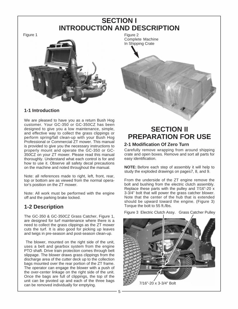
1-1 Introduction
We are pleased to have you as a return Bush Hogcustomer. Your GC-350 or GC-350CZ has beendesigned to give you a low maintenance, simple,and effective way to collect the grass clippings orperform spring/fall clean-up with your Bush HogProfessional or Commercial ZT mower. This manualis provided to give you the necessary instructions toproperly mount and operate the GC-350 or GC-350CZ on your ZT mower. Please read this manualthoroughly. Understand what each control is for andhow to use it. Observe all safety decal precautionson the machine and noted throughout the manual.
Note: all references made to right, left, front, rear,top or bottom are as viewed from the normal opera-tor's position on the ZT mower.
Note: All work must be performed with the engineoff and the parking brake locked.
1-2 Description
The GC-350 & GC-350CZ Grass Catcher, Figure 1,are designed for turf maintenance where there is aneed to collect the grass clippings as the ZT mowercuts the turf. It is also good for picking up leavesand twigs in pre-season and post-season clean-up.
The blower, mounted on the right side of the unit,uses a belt and gearbox system from the enginePTO shaft. Drive train protection comes through beltslippage. The blower draws grass clippings from thedischarge area of the cutter deck up to the collectionbags mounted over the rear portion of the ZT frame.The operator can engage the blower with a push ofthe over-center linkage on the right side of the unit.Once the bags are full of clippings, the top of theunit can be pivoted up and each of the three bagscan be removed individually for emptying.
Figure 1
SECTION IIPREPARATION FOR USE
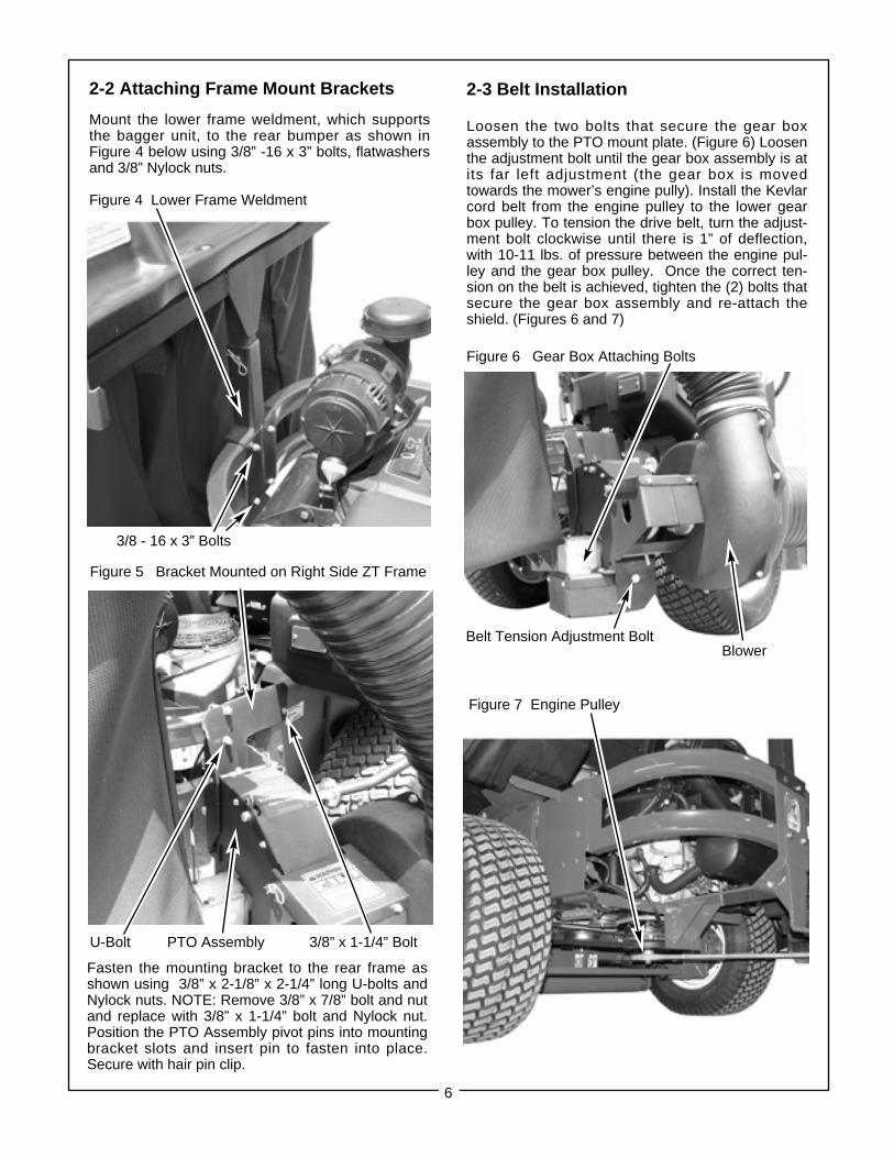
2-1 Modification Of Zero TurnCarefully remove wrapping from around shippingcrate and open boxes. Remove and sort all parts foreasy identification.
NOTE: Before each step of assembly it will help tostudy the exploded drawings on pages7, 8, and 9.
From the underside of the ZT engine remove thebolt and bushing from the electric clutch assembly.Replace these parts with the pulley and 7/16”-20 x3-3/4” bolt that will power the grass catcher blower.Note that the center of the hub that is extendedshould be upward toward the engine. (Figure 3)Torque the bolt to 55 ft./lbs.
Figure 2Complete MachineIn Shipping Crate
Figure 3 Electric Clutch Assy. Grass Catcher Pulley
7/16”-20 x 3-3/4” Bolt
6
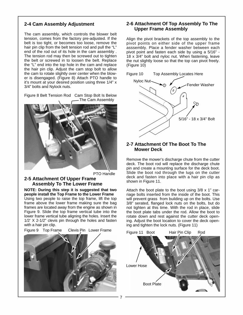
2-3 Belt Installation
Loosen the two bolts that secure the gear boxassembly to the PTO mount plate. (Figure 6) Loosenthe adjustment bolt until the gear box assembly is atits far left adjustment (the gear box is movedtowards the mower’s engine pully). Install the Kevlarcord belt from the engine pulley to the lower gearbox pulley. To tension the drive belt, turn the adjust-ment bolt clockwise until there is 1” of deflection,with 10-11 lbs. of pressure between the engine pul-ley and the gear box pulley. Once the correct ten-sion on the belt is achieved, tighten the (2) bolts thatsecure the gear box assembly and re-attach theshield. (Figures 6 and 7)
Figure 6 Gear Box Attaching Bolts
2-2 Attaching Frame Mount Brackets
Mount the lower frame weldment, which supportsthe bagger unit, to the rear bumper as shown inFigure 4 below using 3/8” -16 x 3” bolts, flatwashersand 3/8” Nylock nuts.
Figure 4 Lower Frame Weldment
Figure 5 Bracket Mounted on Right Side ZT Frame
U-Bolt PTO Assembly 3/8” x 1-1/4” Bolt
Belt Tension Adjustment Bolt
Figure 7 Engine Pulley
Blower
Fasten the mounting bracket to the rear frame asshown using 3/8” x 2-1/8” x 2-1/4” long U-bolts andNylock nuts. NOTE: Remove 3/8” x 7/8” bolt and nutand replace with 3/8” x 1-1/4” bolt and Nylock nut.Position the PTO Assembly pivot pins into mountingbracket slots and insert pin to fasten into place.Secure with hair pin clip.
3/8 - 16 x 3” Bolts
7
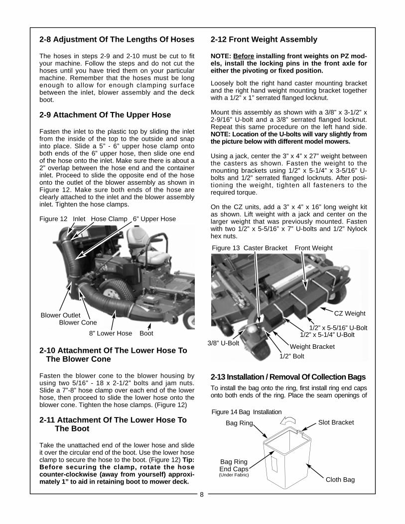
2-4 Cam Assembly Adjustment
The cam assembly, which controls the blower belttension, comes from the factory pre-adjusted. If thebelt is too tight, or becomes too loose, remove thehair pin clip from the belt tension rod and pull the “L”end of the rod out of its hole in the cam assembly .The tension rod may then be screwed out to tightenthe belt or screwed in to loosen the belt. Replacethe “L” end into the top hole in the cam and replacethe hair pin clip. Adjust the cam stop bolt to allowthe cam to rotate slightly over center when the blow-er is disengaged. (Figure 8) Attach PTO handle toit’s mount at your desired position using three 1/4” x3/4” bolts and Nylock nuts.
Figure 8 Belt Tension Rod Cam Stop Bolt Is BelowThe Cam Assembly
2-5 Attachment Of Upper FrameAssembly To The Lower Frame
NOTE: During this step it is suggested that twopeople install the Top Frame to the Lower FrameUsing two people to raise the top frame, lift the topframe above the lower frame making sure the bagframes are located away from the engine as shown inFigure 9. Slide the top frame vertical tube into thelower frame vertical tube aligning the holes. Insert the1/2’ X 2-1/2” clevis pin through the holes and fastenwith a hair pin clip. Figure 9 Top Frame Clevis Pin Lower Frame
2-6 Attachment Of Top Assembly To The Upper Frame Assembly
Align the pivot brackets of the top assembly to thepivot points on either side of the upper frameasssembly. Place a fender washer between eachpivot point and fasten each side by using a 5/16” -18 x 3/4” bolt and nyloc nut. When fastening, leavethe nut slightly loose so that the top can pivot freely.(Figure 10)
Figure 10 Top Assembly Locates Here
2-7 Attachment Of The Boot To TheMower Deck
Remove the mower’s discharge chute from the cutterdeck. The boot rod will replace the discharge chutepin and create a mounting surface for the deck boot.Slide the boot rod through the lugs on the cutterdeck and fasten into place with a hair pin clip asshown in Figure 11.
Attach the boot plate to the boot using 3/8 x 1” car-riage bolts inserted from the inside of the boot. Thiswill prevent grass from building up on the bolts. Use3/8” serated, flanged lock nuts on the bolts, but donot tighten at this time. With the rod in place, slidethe boot plate tabs under the rod. Allow the boot torotate down and rest against the cutter deck open-ing. Adjust the boot location to cover the deck open-ing and tighten the lock nuts. (Figure 11)
Figure 11 Boot Hair Pin Clip Rod
Boot Plate
Lower Hose
Nyloc NutFender Washer
5/16” - 18 x 3/4” Bolt
PTO Handle
2-12 Front Weight Assembly
NOTE: Before installing front weights on PZ mod-els, install the locking pins in the front axle foreither the pivoting or fixed position.
Loosely bolt the right hand caster mounting bracketand the right hand weight mounting bracket togetherwith a 1/2” x 1” serrated flanged locknut.
Mount this assembly as shown with a 3/8” x 3-1/2” x2-9/16” U-bolt and a 3/8” serrated flanged locknut.Repeat this same procedure on the left hand side.NOTE: Location of the U-bolts will vary slightly fromthe picture below with different model mowers.
Using a jack, center the 3” x 4” x 27” weight betweenthe casters as shown. Fasten the weight to themounting brackets using 1/2” x 5-1/4” x 3-5/16” U-bolts and 1/2” serrated flanged locknuts. After posi-tioning the weight, tighten all fasteners to therequired torque.
On the CZ units, add a 3” x 4” x 16” long weight kitas shown. Lift weight with a jack and center on thelarger weight that was previously mounted. Fastenwith two 1/2” x 5-5/16” x 7” U-bolts and 1/2” Nylockhex nuts.
2-13 Installation / Removal Of Collection BagsTo install the bag onto the ring, first install ring end capsonto both ends of the ring. Place the seam openings of
8
2-8 Adjustment Of The Lengths Of Hoses
The hoses in steps 2-9 and 2-10 must be cut to fityour machine. Follow the steps and do not cut thehoses until you have tried them on your particularmachine. Remember that the hoses must be longenough to allow for enough clamping surfacebetween the inlet, blower assembly and the deckboot.
2-9 Attachment Of The Upper Hose
Fasten the inlet to the plastic top by sliding the inletfrom the inside of the top to the outside and snapinto place. Slide a 5” - 6” upper hose clamp ontoboth ends of the 6” upper hose, then slide one endof the hose onto the inlet. Make sure there is about a2” overlap between the hose end and the containerinlet. Proceed to slide the opposite end of the hoseonto the outlet of the blower assembly as shown inFigure 12. Make sure both ends of the hose areclearly attached to the inlet and the blower assemblyinlet. Tighten the hose clamps.
Figure 12 Inlet Hose Clamp 6” Upper Hose
2-10 Attachment Of The Lower Hose ToThe Blower Cone
Fasten the blower cone to the blower housing byusing two 5/16” - 18 x 2-1/2” bolts and jam nuts.Slide a 7”-8” hose clamp over each end of the lowerhose, then proceed to slide the lower hose onto theblower cone. Tighten the hose clamps. (Figure 12)
2-11 Attachment Of The Lower Hose ToThe Boot
Take the unattached end of the lower hose and slideit over the circular end of the boot. Use the lower hoseclamp to secure the hose to the boot. (Figure 12) Tip:Before securing the clamp, rotate the hosecounter-clockwise (away from yourself) approxi-mately 1” to aid in retaining boot to mower deck.
Blower OutletBlower Cone
8” Lower Hose Boot
Bag Ring Slot Bracket
Bag RingEnd Caps(Under Fabric)
Cloth Bag
CZ Weight
Weight Bracket3/8” U-Bolt
1/2” Bolt
1/2” x 5-5/16” U-Bolt1/2” x 5-1/4” U-Bolt
Figure 14 Bag Installation
Figure 13 Caster Bracket Front Weight
9
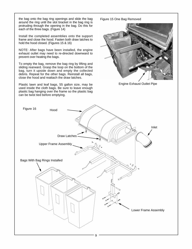
Figure 15 One Bag Removed
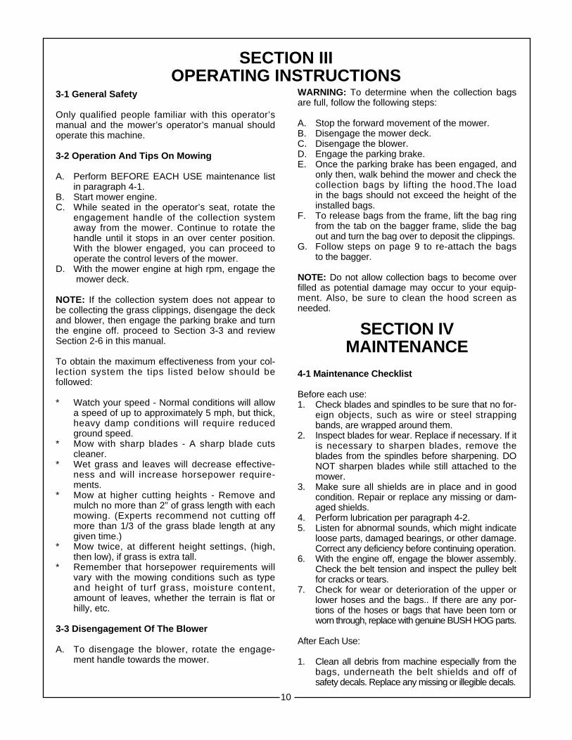
Figure 16 Hood
Draw Latches
Bags With Bag Rings Installed
Upper Frame Assembly
Inlet
the bag onto the bag ring openings and slide the bagaround the ring until the slot bracket in the bag ring isprotruding through the opening in the bag. Do this foreach of the three bags. (Figure 14)
Install the completed assemblies onto the supportframe and close the hood. Fasten both draw latches tohold the hood closed. (Figures 15 & 16)
NOTE: After bags have been installed, the engineexhaust outlet may need to re-directed downward toprevent over heating the bags.
To empty the bag, remove the bag ring by lifting andsliding rearward. Grasp the loop on the bottom of thebag, turn it upside down and empty the collecteddebris. Repeat for the other bags. Reinstall all bags,close the hood and reattach the draw latches.
Plastic lawn and leaf bags, 55 gallon size, may beused inside the cloth bags. Be sure to leave enoughplastic bag hanging over the frame so the plastic bagcan be twist tied before emptying.
Engine Exhaust Outlet Pipe
Lower Frame Assembly
10
SECTION IIIOPERATING INSTRUCTIONS
3-1 General Safety
Only qualified people familiar with this operator’smanual and the mower’s operator’s manual shouldoperate this machine.
3-2 Operation And Tips On Mowing
A. Perform BEFORE EACH USE maintenance listin paragraph 4-1.
B. Start mower engine.C. While seated in the operator’s seat, rotate the
engagement handle of the collection systemaway from the mower. Continue to rotate the handle until it stops in an over center position. With the blower engaged, you can proceed tooperate the control levers of the mower.
D. With the mower engine at high rpm, engage themower deck.
NOTE: If the collection system does not appear tobe collecting the grass clippings, disengage the deckand blower, then engage the parking brake and turnthe engine off. proceed to Section 3-3 and reviewSection 2-6 in this manual.
To obtain the maximum effectiveness from your col-lection system the tips listed below should befollowed:
* Watch your speed - Normal conditions will allowa speed of up to approximately 5 mph, but thick,heavy damp conditions will require reduced ground speed.
* Mow with sharp blades - A sharp blade cutscleaner.
* Wet grass and leaves will decrease effective-ness and will increase horsepower require-ments.
* Mow at higher cutting heights - Remove and mulch no more than 2” of grass length with each mowing. (Experts recommend not cutting off more than 1/3 of the grass blade length at anygiven time.)
* Mow twice, at different height settings, (high,then low), if grass is extra tall.
* Remember that horsepower requirements willvary with the mowing conditions such as typeand height of turf grass, moisture content,amount of leaves, whether the terrain is flat or hilly, etc.
3-3 Disengagement Of The Blower
A. To disengage the blower, rotate the engage-ment handle towards the mower.
WARNING: To determine when the collection bagsare full, follow the following steps:
A. Stop the forward movement of the mower.B. Disengage the mower deck.C. Disengage the blower.D. Engage the parking brake.E. Once the parking brake has been engaged, and
only then, walk behind the mower and check thecollection bags by lifting the hood.The load in the bags should not exceed the height of theinstalled bags.
F. To release bags from the frame, lift the bag ring from the tab on the bagger frame, slide the bag out and turn the bag over to deposit the clippings.
G. Follow steps on page 9 to re-attach the bags to the bagger.
NOTE: Do not allow collection bags to become overfilled as potential damage may occur to your equip-ment. Also, be sure to clean the hood screen asneeded.
SECTION IVMAINTENANCE
4-1 Maintenance Checklist
Before each use:1. Check blades and spindles to be sure that no for-
eign objects, such as wire or steel strappingbands, are wrapped around them.
2. Inspect blades for wear. Replace if necessary. If it is necessary to sharpen blades, remove theblades from the spindles before sharpening. DO NOT sharpen blades while still attached to the mower.
3. Make sure all shields are in place and in goodcondition. Repair or replace any missing or dam-aged shields.
4. Perform lubrication per paragraph 4-2.5. Listen for abnormal sounds, which might indicate
loose parts, damaged bearings, or other damage.Correct any deficiency before continuing operation.
6. With the engine off, engage the blower assembly.Check the belt tension and inspect the pulley belt for cracks or tears.
7. Check for wear or deterioration of the upper or lower hoses and the bags.. If there are any por-tions of the hoses or bags that have been torn orworn through, replace with genuine BUSH HOG parts.
After Each Use:
1. Clean all debris from machine especially from the bags, underneath the belt shields and off of safety decals. Replace any missing or illegible decals.
11
2. Inspect the unit for worn or damaged compo-nents. Repair or replace before next use. Anyreplacement component installed during repairshall include the component’s current safetydecal specified by the manufacturers to beaffixed to the component.
3. Check belt for proper tension.
4-2 Lubrication
NOTE: Use only white lithium base grease for lubri-cation of the shaft on the blower assembly.
1. On the initial use: Grease the fitting on the blow-er shaft.
2. Every 25 hours of use: Re-grease the grease fitting.3. Every 200 hours of use: Check oil levels in gear
box. Oil in gear box should cover the gears. Ifnot, fill using an EP90 weight oil. 6 oz. will fillthe gear box from empty.
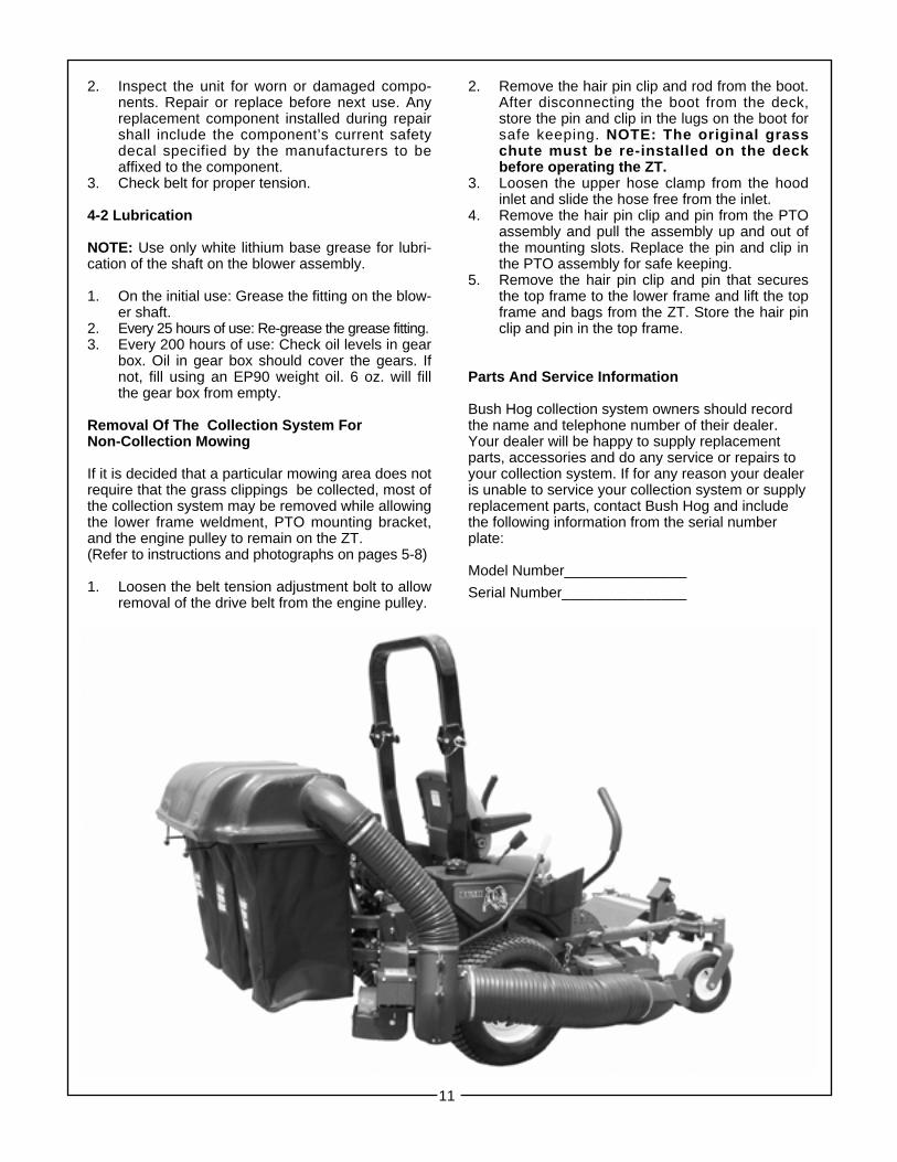
Removal Of The Collection System ForNon-Collection Mowing
If it is decided that a particular mowing area does notrequire that the grass clippings be collected, most ofthe collection system may be removed while allowingthe lower frame weldment, PTO mounting bracket,and the engine pulley to remain on the ZT.(Refer to instructions and photographs on pages 5-8)
1. Loosen the belt tension adjustment bolt to allowremoval of the drive belt from the engine pulley.
2. Remove the hair pin clip and rod from the boot.After disconnecting the boot from the deck,store the pin and clip in the lugs on the boot for safe keeping. NOTE: The original grass chute must be re-installed on the deckbefore operating the ZT.
3. Loosen the upper hose clamp from the hoodinlet and slide the hose free from the inlet.
4. Remove the hair pin clip and pin from the PTOassembly and pull the assembly up and out ofthe mounting slots. Replace the pin and clip in the PTO assembly for safe keeping.
5. Remove the hair pin clip and pin that secures the top frame to the lower frame and lift the top frame and bags from the ZT. Store the hair pinclip and pin in the top frame.
Parts And Service Information
Bush Hog collection system owners should recordthe name and telephone number of their dealer.Your dealer will be happy to supply replacementparts, accessories and do any service or repairs toyour collection system. If for any reason your dealeris unable to service your collection system or supplyreplacement parts, contact Bush Hog and includethe following information from the serial numberplate:
Model Number_______________
Serial Number_______________

SAFETY DECALSTo promote safe operation, Bush Hog supplies safety decals on all products manufactured. Because damagecan occur to safety decals either through shipment, use or reconditioning, Bush Hog will, upon request, providesafety decals for any of our products in the field at no charge. Contact your authorized Bush Hog dealer formore information.
12
5003130150031304
50031303
50031302
5005291550052916
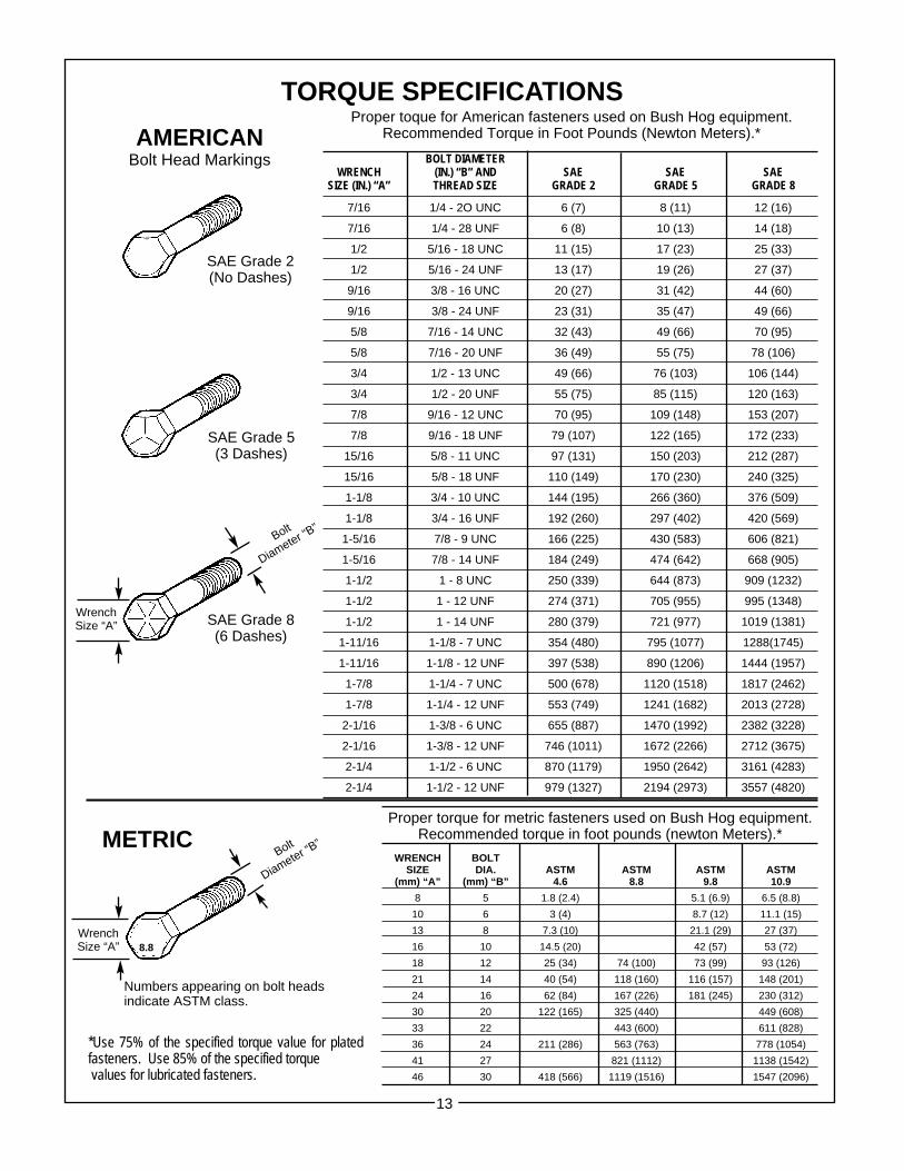
TORQUE SPECIFICATIONSProper toque for American fasteners used on Bush Hog equipment.
Recommended Torque in Foot Pounds (Newton Meters).*
BOLT DIAMETERWRENCH (IN.) “B” AND SAE SAE SAE
SIZE (IN.) “A” THREAD SIZE GRADE 2 GRADE 5 GRADE 8
7/16 1/4 - 2O UNC 6 (7) 8 (11) 12 (16)
7/16 1/4 - 28 UNF 6 (8) 10 (13) 14 (18)
1/2 5/16 - 18 UNC 11 (15) 17 (23) 25 (33)
1/2 5/16 - 24 UNF 13 (17) 19 (26) 27 (37)
9/16 3/8 - 16 UNC 20 (27) 31 (42) 44 (60)
9/16 3/8 - 24 UNF 23 (31) 35 (47) 49 (66)
5/8 7/16 - 14 UNC 32 (43) 49 (66) 70 (95)
5/8 7/16 - 20 UNF 36 (49) 55 (75) 78 (106)
3/4 1/2 - 13 UNC 49 (66) 76 (103) 106 (144)
3/4 1/2 - 20 UNF 55 (75) 85 (115) 120 (163)
7/8 9/16 - 12 UNC 70 (95) 109 (148) 153 (207)
7/8 9/16 - 18 UNF 79 (107) 122 (165) 172 (233)
15/16 5/8 - 11 UNC 97 (131) 150 (203) 212 (287)
15/16 5/8 - 18 UNF 110 (149) 170 (230) 240 (325)
1-1/8 3/4 - 10 UNC 144 (195) 266 (360) 376 (509)
1-1/8 3/4 - 16 UNF 192 (260) 297 (402) 420 (569)
1-5/16 7/8 - 9 UNC 166 (225) 430 (583) 606 (821)
1-5/16 7/8 - 14 UNF 184 (249) 474 (642) 668 (905)
1-1/2 1 - 8 UNC 250 (339) 644 (873) 909 (1232)
1-1/2 1 - 12 UNF 274 (371) 705 (955) 995 (1348)
1-1/2 1 - 14 UNF 280 (379) 721 (977) 1019 (1381)
1-11/16 1-1/8 - 7 UNC 354 (480) 795 (1077) 1288(1745)
1-11/16 1-1/8 - 12 UNF 397 (538) 890 (1206) 1444 (1957)
1-7/8 1-1/4 - 7 UNC 500 (678) 1120 (1518) 1817 (2462)
1-7/8 1-1/4 - 12 UNF 553 (749) 1241 (1682) 2013 (2728)
2-1/16 1-3/8 - 6 UNC 655 (887) 1470 (1992) 2382 (3228)
2-1/16 1-3/8 - 12 UNF 746 (1011) 1672 (2266) 2712 (3675)
2-1/4 1-1/2 - 6 UNC 870 (1179) 1950 (2642) 3161 (4283)
2-1/4 1-1/2 - 12 UNF 979 (1327) 2194 (2973) 3557 (4820)
Proper torque for metric fasteners used on Bush Hog equipment.Recommended torque in foot pounds (newton Meters).*
WRENCH BOLTSIZE DIA. ASTM ASTM ASTM ASTM
(mm) “A” (mm) “B” 4.6 8.8 9.8 10.9
8 5 1.8 (2.4) 5.1 (6.9) 6.5 (8.8)
10 6 3 (4) 8.7 (12) 11.1 (15)
13 8 7.3 (10) 21.1 (29) 27 (37)
16 10 14.5 (20) 42 (57) 53 (72)
18 12 25 (34) 74 (100) 73 (99) 93 (126)
21 14 40 (54) 118 (160) 116 (157) 148 (201)
24 16 62 (84) 167 (226) 181 (245) 230 (312)
30 20 122 (165) 325 (440) 449 (608)
33 22 443 (600) 611 (828)
36 24 211 (286) 563 (763) 778 (1054)
41 27 821 (1112) 1138 (1542)
46 30 418 (566) 1119 (1516) 1547 (2096)
*Use 75% of the specified torque value for platedfasteners. Use 85% of the specified torquevalues for lubricated fasteners.
Numbers appearing on bolt headsindicate ASTM class.
METRIC
AMERICANBolt Head Markings
WrenchSize “A”
Bolt
Diameter “B”
SAE Grade 8(6 Dashes)
SAE Grade 2(No Dashes)
SAE Grade 5(3 Dashes)
WrenchSize “A” 8.8
Bolt
Diameter “B”
13

P.O. Box 1039 ● Selma, AL 36702-1039Telephone (334) 874-2700 ● www.bushhog.com