Embed Size (px)
DESCRIPTION
bus truncking system
Citation preview

Corporate Mission
Mission & Quality policy
he Controls & Switchgear Co. Ltd
aims to be the world's leading
BUSDUCT / BUSTRUNKING manufacturer.
It will seek to be the industry benchmark
in terms of quality and reliability of product
and speed and efficiency of execution.
The Controls & Switchgear Co. Ltd
intends to achive this leadership status
by leveraging the combination of
world class product design,
manufacturing infrastructure, engineering
acumern and customer service.
T
2
We are committed to achieve excellence in design and Manufacturing of Busduct and Busbartrunking System through:
Upgrading Equipments & QA system as per latest Standards and Customers Requirements.
Quick readdressal of Customer Concern taking corrective and preventive actions.
Providing adequate resources including Infrastructure & Competent Personnel.
We are committed to review our Quality Management Systems to achieve continual improvements.
QUALITY POLICY
2
3
CONTR S &TCH E
PTD
OL SWI
G AR COM ANY L .
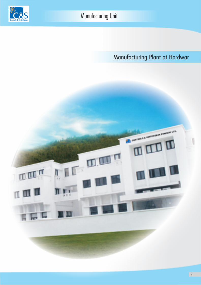
Manufacturing Plant at Hardwar
Manufacturing Unit
3
4
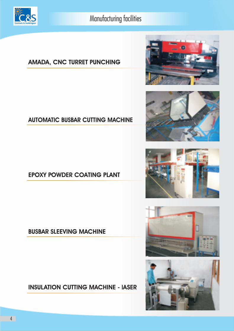
Manufacturing facilities
AMADA, CNC TURRET PUNCHING
AUTOMATIC BUSBAR CUTTING MACHINE
EPOXY POWDER COATING PLANT
BUSBAR SLEEVING MACHINE
INSULATION CUTTING MACHINE - lASER
5
Contents
Technical Parameters
Standard & Specifications
Bustrunking System 11
Main Components
A) Feeder Bustrunking, Plug-in Bustrunking 12
B) Uni-Block Busbar Joint 13
C) Horizontal elbow, Horizontal offset elbow 14
D) Vertical elbow, Vertical offset elbow, Vertical Tee Section 15
E) Certification & Approvals 16 - 17
F) Standard Flange End 18
G) Flange End Box, Rubber Bellow & Flexibles 19
h) Plug in Boxes 20
I) Spring & Rigid Hanger 21
Other Components 22
Complete Engineering Solution 23
Installation Instructions 24 - 27
Major installations 28 - 29
Major Export orders 30
Other Busbar Systems 31
6 - 9
10
6
Technical Parameters
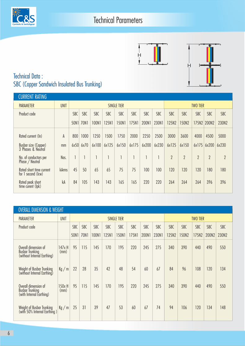
Technical Data : SBC (Copper Sandwich Insulated Bus Trunking)
OVERALL DIMENSION & WEIGHT
PARAMETER UNIT SINGLE TIER TWO TIER
Product code SBC SBC SBC SBC SBC SBC SBC SBC SBC SBC SBC SBC SBC
50N1 70N1 100N1 125N1 150N1 175N1 200N1 230N1 125N2 150N2 175N2 200N2 230N2
Rated current (In) A 800 1000 1250 1500 1750 2000 2250 2500 3000 3600 4000 4500 5000
Busbar size (Copper) mm 6x50 6x70 6x100 6x125 6x150 6x175 6x200 6x230 6x125 6x150 6x175 6x200 6x2303 Phases & Neutral
No. of conductors per Nos. 1 1 1 1 1 1 1 1 2 2 2 2 2Phase / Neutral
Rated short time current kArms 45 50 65 65 75 75 100 100 120 120 120 180 180for 1 second (Icw)
Rated peak short kA 84 105 143 143 165 165 220 220 264 264 264 396 396time curent (Ipk)
PARAMETER UNIT SINGLE TIER TWO TIER
Product code SBC SBC SBC SBC SBC SBC SBC SBC SBC SBC SBC SBC SBC
50N1 70N1 100N1 125N1 150N1 175N1 200N1 230N1 125N2 150N2 175N2 200N2 230N2
Overall dimension of 147x H 95 115 145 170 195 220 245 275 340 390 440 490 550Busbar Trunking (mm)(without Internal Earthing)
Weight of Busbar Trunking Kg / m 22 28 35 42 48 54 60 67 84 96 108 120 134(without Internal Earthing)
Overall dimension of 150x H 95 115 145 170 195 220 245 275 340 390 440 490 550Busbar Trunking (mm) (with Internal Earthing)
Weight of Busbar Trunking Kg / m 25 31 39 47 53 60 67 74 94 106 120 134 148(with 50% Internal Earthing )
CURRENT RATING
H
H
7
Technical Parameters
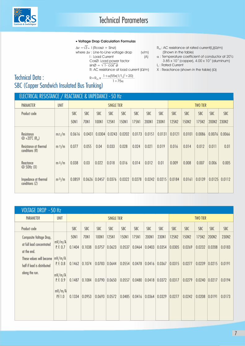
Technical Data : SBC (Copper Sandwich Insulated Bus Trunking)
VOLTAGE DROP - 50 Hz
Composite Voltage Drop,
at full load concentrated
at the end.
These values will become
half if load is distributed
along the run.
mV/m/A
mV/m/A
mV/m/A
mV/m/A
· Voltage Drop Calculation Formulas
Dv =Ö3 I (RcosØ + SinØ)
where Dv : Line-to-Line voltage drop (v/m)
I : Load Current (A) CosØ: Load power factor
2 sinØ = Ö 1- cos ø R: AC resistance at load current (W/m) R=R x 95
· R : AC resistance at rated current(I )(W/m)95 0
(Shown in the table) oa : Temperature coefficient of conductor at 20 c
-3 -3 3.85 x 10 (copper), 4.00 x 10 (aluminum)I : Rated Current0
X : Reactance (shown in the table) (W)
21+a(55x(1/1 ) +20)0
1+75a
ELECTRICAL RESISTANCE / REACTANCE & IMPEDANCE - 50 Hz
PARAMETER UNIT SINGLE TIER TWO TIER
Product code SBC SBC SBC SBC SBC SBC SBC SBC SBC SBC SBC SBC SBC
50N1 70N1 100N1 125N1 150N1 175N1 200N1 230N1 125N2 150N2 175N2 200N2 230N2
Resistance m /m 0.0616 0.0431 0.0304 0.0243 0.0202 0.0173 0.0151 0.0131 0.0121 0.0101 0.0086 0.0076 0.00660@ +20 C (R )20
Resistance at thermal m /m 0.077 0.055 0.04 0.033 0.028 0.024 0.021 0.019 0.016 0.014 0.012 0.011 0.01conditions (R)
Reactance m /m 0.038 0.03 0.022 0.018 0.016 0.014 0.012 0.01 0.009 0.008 0.007 0.006 0.005@ 50Hz (X)
Impedance at thermal m /m 0.0859 0.0626 0.0457 0.0376 0.0322 0.0278 0.0242 0.0215 0.0184 0.0161 0.0139 0.0125 0.0112conditions (Z)
Product code SBC SBC SBC SBC SBC SBC SBC SBC SBC SBC SBC SBC SBC
50N1 70N1 100N1 125N1 150N1 175N1 200N1 230N1 125N2 150N2 175N2 200N2 230N2
P. F. 0.7 0.1404 0.1038 0.0757 0.0623 0.0537 0.0464 0.0403 0.0354 0.0305 0.0269 0.0232 0.0208 0.0183
P. F. 0.8 0.1462 0.1074 0.0783 0.0644 0.0554 0.0478 0.0416 0.0367 0.0315 0.0277 0.0239 0.0215 0.0191
P. F. 0.9 0.1487 0.1084 0.0790 0.0650 0.0557 0.0480 0.0418 0.0372 0.0317 0.0279 0.0240 0.0217 0.0194
P.F.1.0 0.1334 0.0953 0.0693 0.0572 0.0485 0.0416 0.0364 0.0329 0.0277 0.0242 0.0208 0.0191 0.0173
PARAMETER UNIT TWO TIERSINGLE TIER
8
Technical Parameters
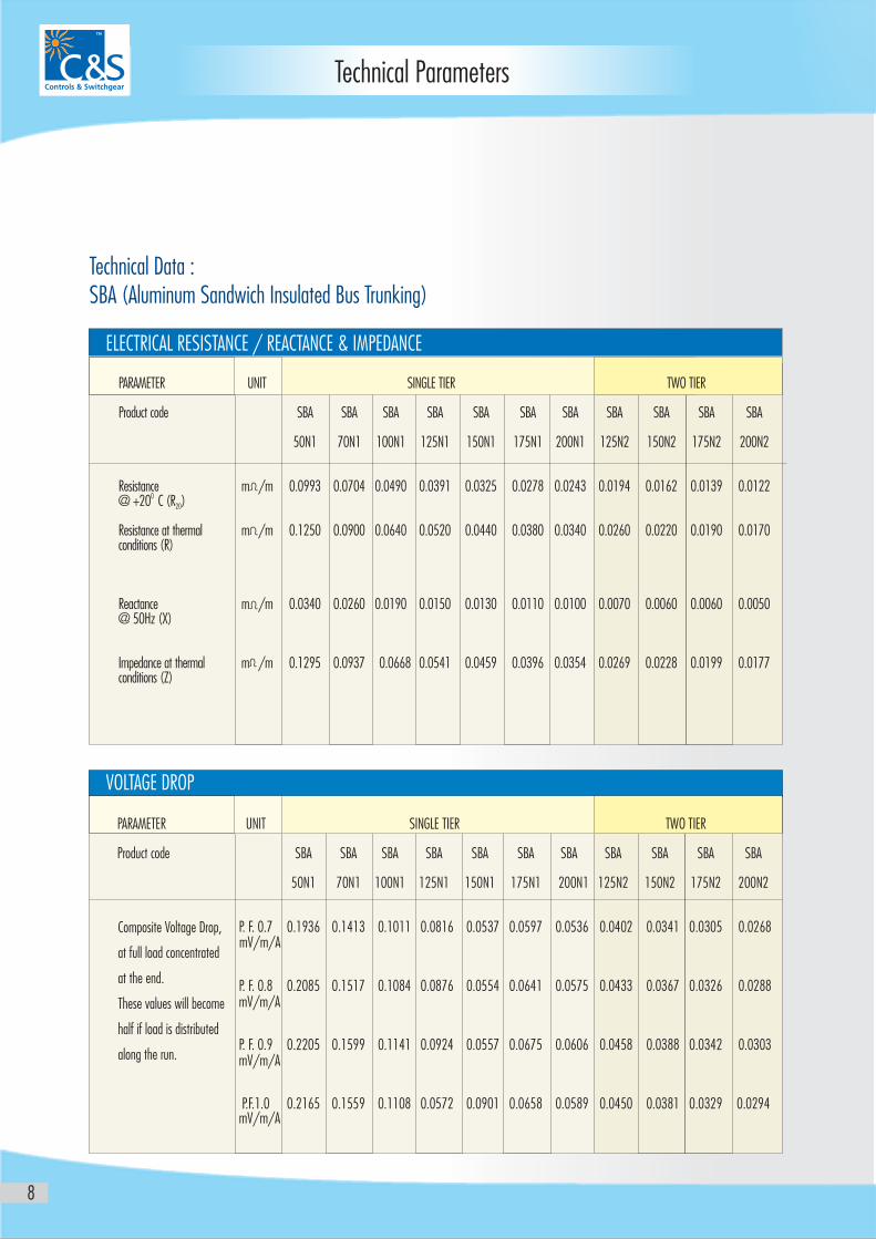
Technical Data : SBA (Aluminum Sandwich Insulated Bus Trunking)
ELECTRICAL RESISTANCE / REACTANCE & IMPEDANCE
PARAMETER UNIT SINGLE TIER TWO TIER
Product code SBA SBA SBA SBA SBA SBA SBA SBA SBA SBA SBA
50N1 70N1 100N1 125N1 150N1 175N1 200N1 125N2 150N2 175N2 200N2
Resistance m /m 0.0993 0.0704 0.0490 0.0391 0.0325 0.0278 0.0243 0.0194 0.0162 0.0139 0.01220 @ +20 C (R )20
Resistance at thermal m /m 0.1250 0.0900 0.0640 0.0520 0.0440 0.0380 0.0340 0.0260 0.0220 0.0190 0.0170conditions (R)
Reactance m /m 0.0340 0.0260 0.0190 0.0150 0.0130 0.0110 0.0100 0.0070 0.0060 0.0060 0.0050@ 50Hz (X)
Impedance at thermal m /m 0.1295 0.0937 0.0668 0.0541 0.0459 0.0396 0.0354 0.0269 0.0228 0.0199 0.0177conditions (Z)
PARAMETER UNIT SINGLE TIER TWO TIER
Product code SBA SBA SBA SBA SBA SBA SBA SBA SBA SBA SBA
50N1 70N1 100N1 125N1 150N1 175N1 200N1 125N2 150N2 175N2 200N2
P. F. 0.7 0.1936 0.1413 0.1011 0.0816 0.0537 0.0597 0.0536 0.0402 0.0341 0.0305 0.0268
P. F. 0.8 0.2085 0.1517 0.1084 0.0876 0.0554 0.0641 0.0575 0.0433 0.0367 0.0326 0.0288
P. F. 0.9 0.2205 0.1599 0.1141 0.0924 0.0557 0.0675 0.0606 0.0458 0.0388 0.0342 0.0303
P.F.1.0 0.2165 0.1559 0.1108 0.0572 0.0901 0.0658 0.0589 0.0450 0.0381 0.0329 0.0294
VOLTAGE DROP
Composite Voltage Drop,
at full load concentrated
at the end.
These values will become
half if load is distributed
along the run.
mV/m/A
mV/m/A
mV/m/A
mV/m/A
Technical Parameters
9
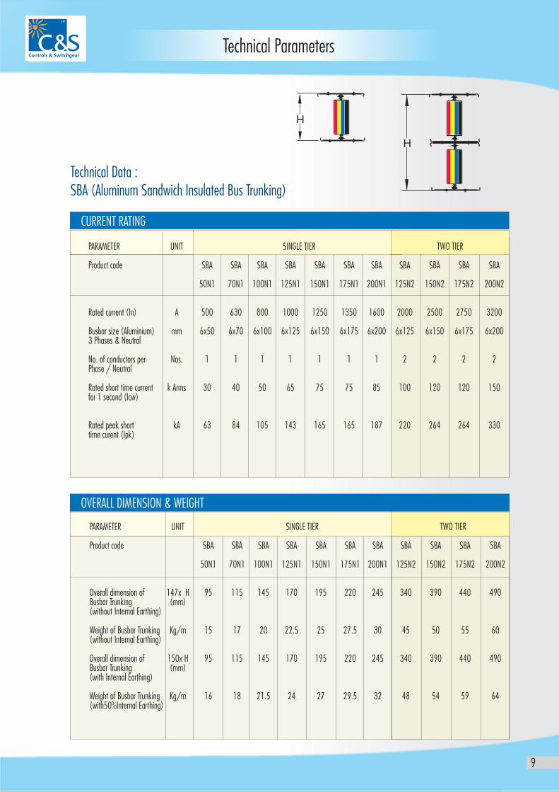
Technical Data : SBA (Aluminum Sandwich Insulated Bus Trunking)
CURRENT RATING
OVERALL DIMENSION & WEIGHT
PARAMETER UNIT SINGLE TIER TWO TIER
Product code SBA SBA SBA SBA SBA SBA SBA SBA SBA SBA SBA
50N1 70N1 100N1 125N1 150N1 175N1 200N1 125N2 150N2 175N2 200N2
Overall dimension of 147x H 95 115 145 170 195 220 245 340 390 440 490Busbar Trunking (mm)(without Internal Earthing)
Weight of Busbar Trunking Kg/m 15 17 20 22.5 25 27.5 30 45 50 55 60(without Internal Earthing)
Overall dimension of 150x H 95 115 145 170 195 220 245 340 390 440 490Busbar Trunking (mm) (with Internal Earthing)
Weight of Busbar Trunking Kg/m 16 18 21.5 24 27 29.5 32 48 54 59 64(with50%Internal Earthing)
PARAMETER UNIT SINGLE TIER TWO TIER
Product code SBA SBA SBA SBA SBA SBA SBA SBA SBA SBA SBA
50N1 70N1 100N1 125N1 150N1 175N1 200N1 125N2 150N2 175N2 200N2
Rated current (In) A 500 630 800 1000 1250 1350 1600 2000 2500 2750 3200
Busbar size (Aluminium) mm 6x50 6x70 6x100 6x125 6x150 6x175 6x200 6x125 6x150 6x175 6x2003 Phases & Neutral
No. of conductors per Nos. 1 1 1 1 1 1 1 2 2 2 2Phase / Neutral
Rated short time current k Arms 30 40 50 65 75 75 85 100 120 120 150for 1 second (Icw)
Rated peak short kA 63 84 105 143 165 165 187 220 264 264 330time curent (Ipk)
H
H
10
Standard & Specifications
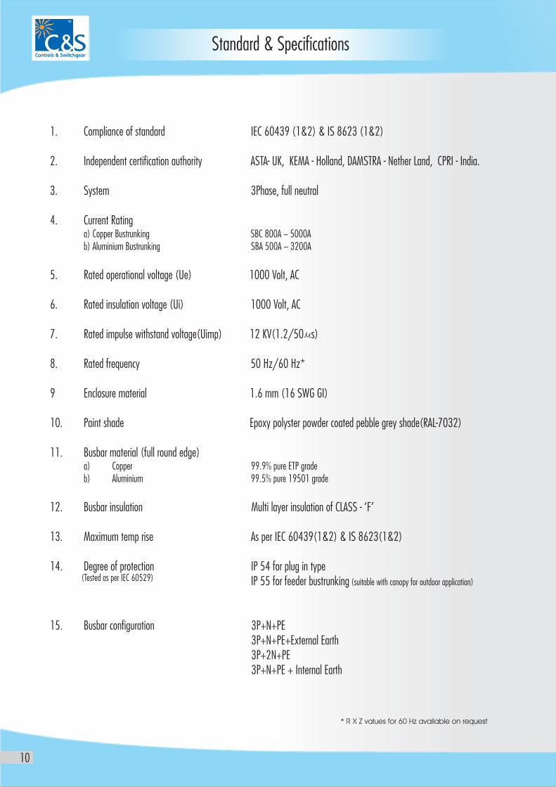
3P+N+PE3P+N+PE+External Earth3P+2N+PE3P+N+PE + Internal Earth
1. Compliance of standard IEC 60439 (1&2) & IS 8623 (1&2)
2. Independent certification authority ASTA- UK, KEMA - Holland, DAMSTRA - Nether Land, CPRI - India.
3. System 3Phase, full neutral
4. Current Ratinga) Copper Bustrunking SBC 800A ~ 5000Ab) Aluminium Bustrunking SBA 500A ~ 3200A
5. Rated operational voltage (Ue) 1000 Volt, AC
6. Rated insulation voltage (Ui) 1000 Volt, AC
7. Rated impulse withstand voltage(Uimp) 12 KV(1.2/50 s)
8. Rated frequency 50 Hz/60 Hz*
9 Enclosure material 1.6 mm (16 SWG GI)
10. Paint shade Epoxy polyster powder coated pebble grey shade(RAL-7032)
11. Busbar material (full round edge)a) Copper 99.9% pure ETP gradeb) Aluminium 99.5% pure 19501 grade
12. Busbar insulation Multi layer insulation of CLASS - ‘F’
13. Maximum temp rise As per IEC 60439(1&2) & IS 8623(1&2)
14. Degree of protection IP 54 for plug in typeIP 55 for feeder bustrunking (suitable with canopy for outdoor application)
15. Busbar configuration
* R X Z values for 60 Hz available on request
(Tested as per IEC 60529)
AN EDFL G E D XN BO
LAN ED ENDF G
L ..VSWI CH EAT G R
P G IN BOLU X
BPLUG IN OX
P G IN S TLU BU DUC
BLECA
LOSEND C URE
F ED IN OXE B
PLUG IN BOX
E CLOS END UR
E CLOS REND U
E CLOS REND U
PLUG INBOX
LU NP G IBOX
PLUG INBOX
EDGEWISEHANGER
I S LA DN U TE U D B S UCT
I S LAN U TED BUSDUCT
I S LATE U D CTN U D B S U
D OXFEE IN B
OXFEED IN B
H I TOR ZON ALLBE OW
HORIZONTALSOFF- ET
ERV TICALOWELB
Bustrunking System
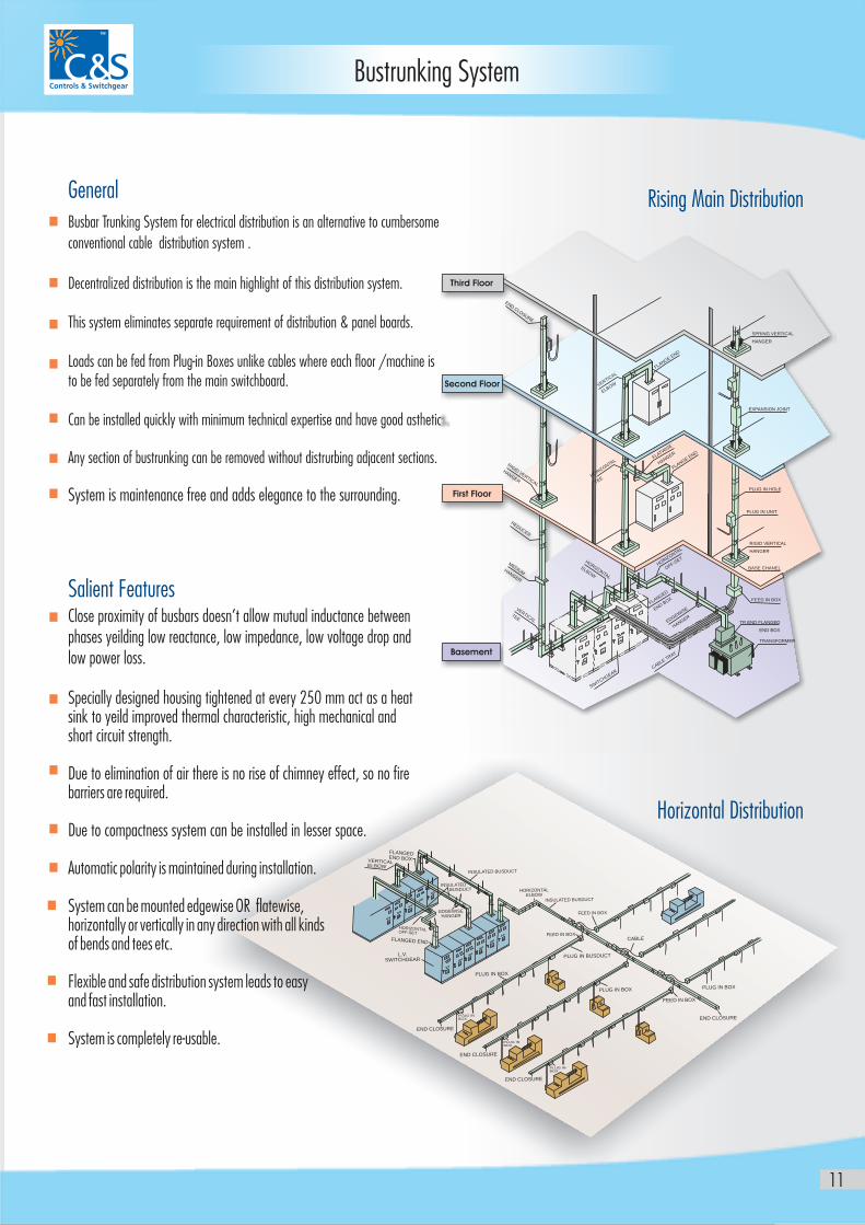
General
Busbar Trunking System for electrical distribution is an alternative to cumbersome
conventional cable distribution system .
Decentralized distribution is the main highlight of this distribution system.
This system eliminates separate requirement of distribution & panel boards.
Loads can be fed from Plug-in Boxes unlike cables where each floor /machine is to be fed separately from the main switchboard.
Can be installed quickly with minimum technical expertise and have good asthetics.
Any section of bustrunking can be removed without distrurbing adjacent sections.
System is maintenance free and adds elegance to the surrounding.
Close proximity of busbars doesn’t allow mutual inductance between phases yeilding low reactance, low impedance, low voltage drop and low power loss.
Specially designed housing tightened at every 250 mm act as a heatsink to yeild improved thermal characteristic, high mechanical andshort circuit strength.
Due to elimination of air there is no rise of chimney effect, so no firebarriers are required.
Due to compactness system can be installed in lesser space.
Automatic polarity is maintained during installation.
System can be mounted edgewise OR flatewise, horizontally or vertically in any direction with all kinds of bends and tees etc.
Flexible and safe distribution system leads to easy and fast installation.
System is completely re-usable.
Salient Features
Rising Main Distribution
Horizontal Distribution
11
N
S
ED CLO
URE
RD
T
L
IGI VER
ICAE
HANGR
REDUCER
MEDIUMHANGER
HORIZONTAL
EOW
LB
VERTICALTEE
I CGEA
SWT
H
R
ABLE TRA
C
Y
DG
SE
EEW
I
HG
ANER
F
ED
LANG
NBOX
ED
H
O
ORIZNTAL
FOF
-SET
G
FLANE
ENDW
FLATIS
E
HG
ANER
H
N
ORIZOTAL
ETE
L
VERTICA
ELBOW
F
D
LANGE EN
T CSPRING VER I AL
ERHANG
EXPANSION J INO T
PLU I HO EG N L
PL UUG IN NIT
R I T CIG D VER I AL
H EANG R
BASE CH ANEL
FEED IN BOX
EN ANGTR D FL ED
D XEN BO
T SFRAN ORMER
Third Floor
Second Floor
First Floor
Basement

12
Main Components
Plug-in Bustrunking
Where branch loads are to be fed from the main line.
Vertical Rising mains to various floors with help of Plug - in Boxes.
Plug-in Points shown are indicative only.
Rating and Number of plug-in-points shall be as per the site requirement .
Feeder BustrunkingStraight length is used for the purpose of power transmission.
Transformer to Panel
Main Panel to Sub Panel
Generator to Panel
Panel to rising mains..
L
0
m
300 m
L - 3 Meter Standard Length
13
Main Components
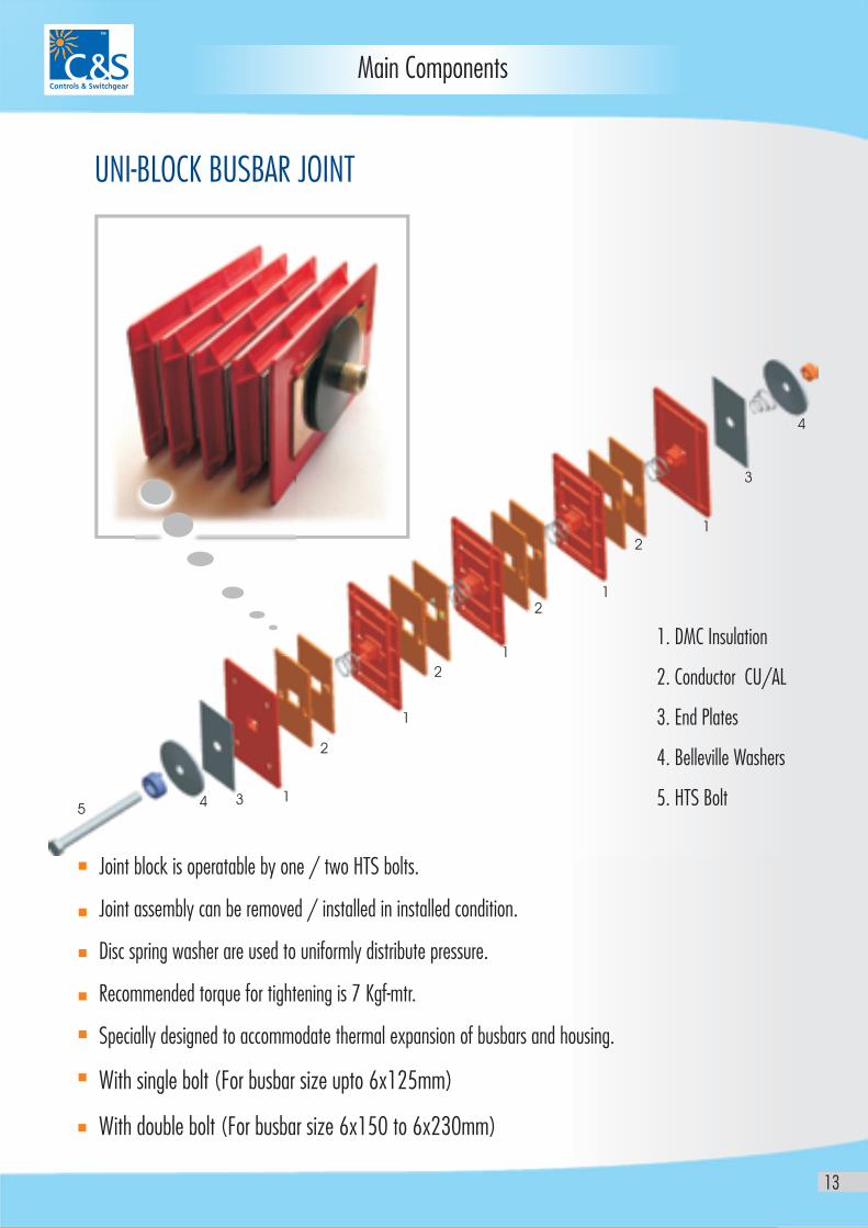
UNI-BLOCK BUSBAR JOINT
Joint block is operatable by one / two HTS bolts.
Joint assembly can be removed / installed in installed condition.
Disc spring washer are used to uniformly distribute pressure.
Recommended torque for tightening is 7 Kgf-mtr.
Specially designed to accommodate thermal expansion of busbars and housing.
With single bolt (For busbar size upto 6x125mm)
With double bolt (For busbar size 6x150 to 6x230mm)
1. DMC Insulation
2. Conductor CU/AL
3. End Plates
4. Belleville Washers
5. HTS Bolt5
4
4
1
1
1
1
1
2
2
2
2
3
3
14
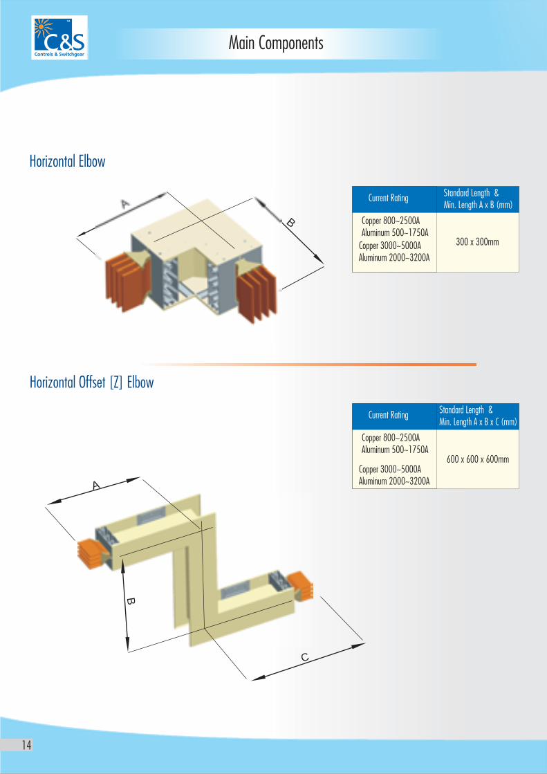
Standard Length & Min. Length A x B x C (mm)
600 x 600 x 600mm
Copper 800~2500A Aluminum 500~1750A
Copper 3000~5000AAluminum 2000~3200A
Current Rating
Standard Length & Min. Length A x B (mm)
300 x 300mm
Copper 800~2500A Aluminum 500~1750A
Copper 3000~5000AAluminum 2000~3200A
Current Rating
Horizontal Offset [Z] Elbow
Horizontal Elbow
A
B
A
B
C
Main Components
15
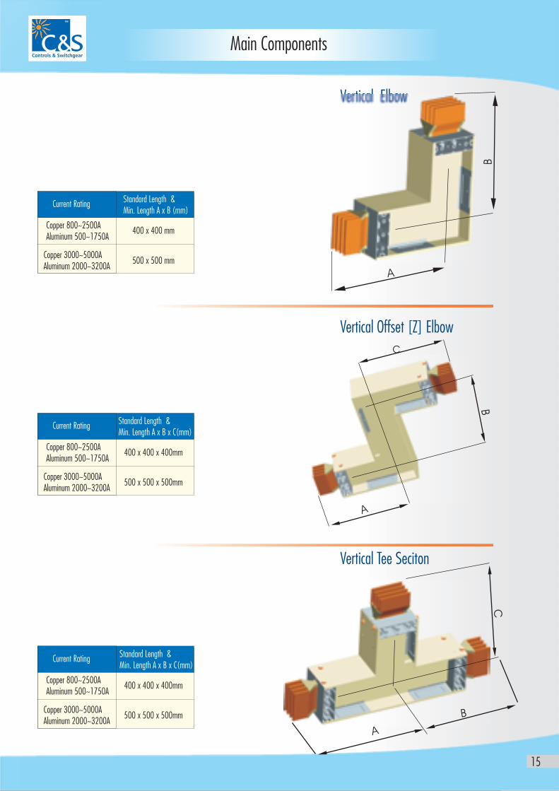
Main Components
Standard Length & Min. Length A x B (mm)
400 x 400 mm Copper 800~2500A Aluminum 500~1750A
Copper 3000~5000AAluminum 2000~3200A
Current Rating
500 x 500 mm
Standard Length & Min. Length A x B x C(mm)
400 x 400 x 400mm Copper 800~2500A Aluminum 500~1750A
Copper 3000~5000AAluminum 2000~3200A
Current Rating
500 x 500 x 500mm
Standard Length & Min. Length A x B x C(mm)
400 x 400 x 400mm Copper 800~2500A Aluminum 500~1750A
Copper 3000~5000AAluminum 2000~3200A
Current Rating
500 x 500 x 500mm
Vertical Offset [Z] Elbow
Vertical Tee Seciton
Vertical Elbow
B
A
C
B
A
C
B
A
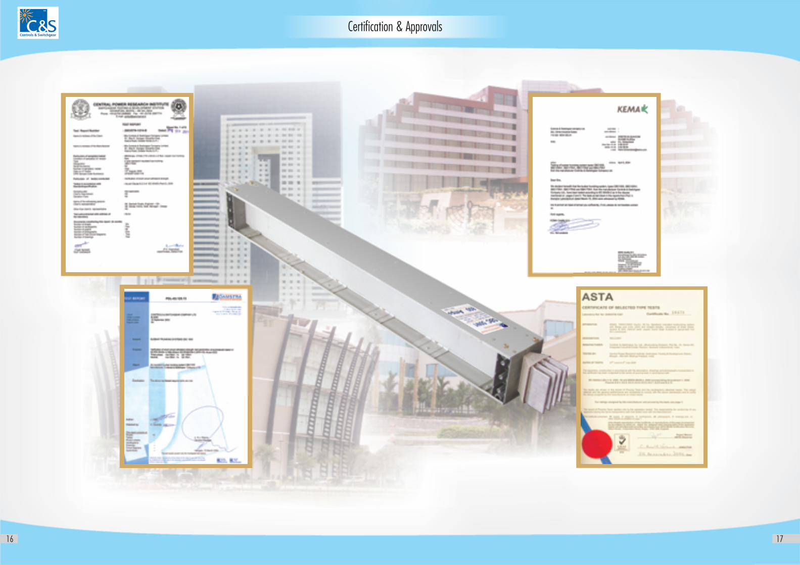
Certification & Approvals
16 17
18
Main Components
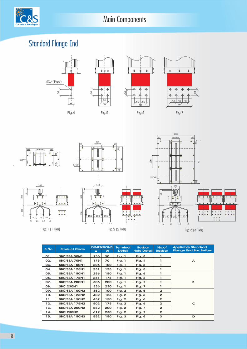
Standard Flange End
01.
02.
03.
04.
05.
06.
07.
08.
09.
10.
11.
12.
13.
14.
15.
SBC/SBA 50N1
SBC/SBA 70N1
SBC/SBA 100N1
SBC/SBA 125N1
SBC/SBA 150N1
SBC/SBA 175N1
SBC/SBA 200N1
SBC 230N1
SBC/SBA 100N2
SBC/SBA 125N2
SBC/SBA 150N2
SBC/SBA 175N2
SBC/SBA 200N2
SBC 230N2
SBC/SBA 150N3
155
175
206
231
256
281
306
336
352
402
452
502
552
612
552
50
70
100
125
150
175
200
230
100
125
150
175
200
230
150
Fig. 1
Fig. 1
Fig. 1
Fig. 1
Fig. 1
Fig. 1
Fig. 1
Fig. 1
Fig. 2
Fig. 2
Fig. 2
Fig. 2
Fig. 2
Fig. 2
Fig. 3
Fig. 4
Fig. 4
Fig. 5
Fig. 5
Fig. 6
Fig. 6
Fig. 7
Fig. 7
Fig. 5
Fig. 5
Fig. 6
Fig. 6
Fig. 7
Fig. 7
Fig. 6
1
1
1
1
1
1
1
1
2
2
2
2
2
2
3
A
B
C
D
S.No Product CodeTerminal
DetailBusbar
Hole DetailNo.of
Basbar
DIMENSIONS
A W
Appliable StandradFlange End Box Bellow
Fig.1 (1 Tier)
Fig.4 Fig.5 Fig.6 Fig.7
Fig.2 (2 Tier) Fig.3 (3 Tier)
50
W
= =
=
=
=
=
150
150
150
60 60
60
60
60
60
690
690
60
60
60
60
60
60
16 16
30
0
30
03
002
00
15TYP
148 148
NN
L1L1
L2L2
L3L3
120 120 120150 150 150
15TYP
5TYP
A A
19
6
A
W
Æ14(Type)
W WW
5050 50 50
50
50
50 50
50
X X X
16
30
03
00
148
N L1 L2 L3
150 150 150
X XX
19
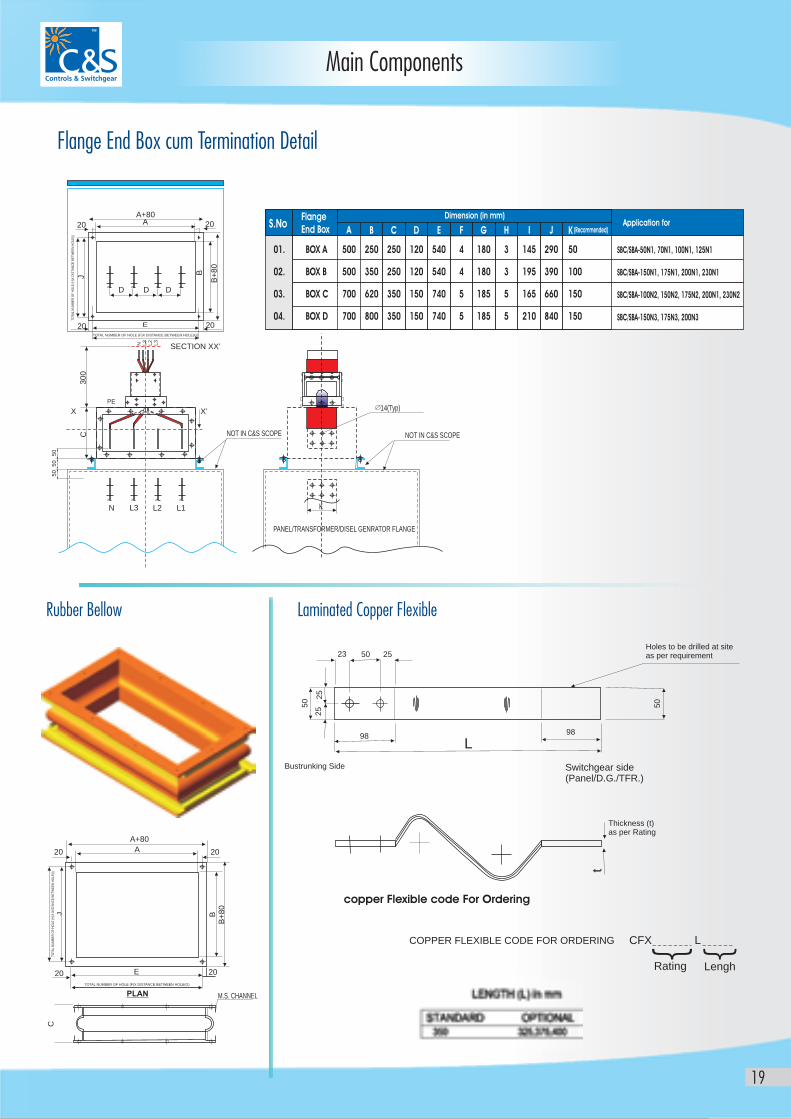
Rubber Bellow
01.
02.
03.
04.
BOX A
BOX B
BOX C
BOX D
500
500
700
700
250
350
620
800
250
250
350
350
120
120
150
150
540
540
740
740
4
4
5
5
3
3
5
5
180
180
185
185
145
195
165
210
290
390
660
840
50
100
150
150
SBC/SBA-50N1, 70N1, 100N1, 125N1
SBC/SBA-150N1, 175N1, 200N1, 230N1
SBC/SBA-100N2, 150N2, 175N2, 200N1, 230N2
SBC/SBA-150N3, 175N3, 200N3
S.NoFlangeEnd Box
Dimension (in mm)Application for
A B C D E F G H I J K (Recommended)
Flange End Box cum Termination Detail
Laminated Copper Flexible
N L3 L2 L1
50
50
50
X
PE
X’
NOT IN C&S SCOPE
SECTION XX’
C3
00
N L3
L2
L3
TOTAL NUMBER OF HOLE (F)X DISTANCE BETWEEN HOLE(G)
TOTA
L N
UM
BE
R O
F H
OLE
(H
)X D
ISTA
NC
E B
ET
WE
EN
HO
LE(I
)
20 A
D
J B+
80
D D
A+8020
2020 E
B
NOT IN C&S SCOPE
PANEL/TRANSFORMER/DISEL GENRATOR FLANGE
K
14(Typ)
TOTAL NUMBER OF HOLE (F)X DISTANCE BETWEEN HOLE(G)
TOTA
L N
UM
BE
R O
F H
OLE
(H
)X D
ISTA
NC
E B
ET
WE
EN
HO
LE(I
)
A+80
A 20
M.S. CHANNEL
20 20
20
B
CJ
B+
80
E
PLAN
copper Flexible code For Ordering
Holes to be drilled at siteas per requirement
Thickness (t)as per Rating
COPPER FLEXIBLE CODE FOR ORDERING CFX
t
50
50
25
50 25
L98
Switchgear side(Panel/D.G./TFR.)
Bustrunking Side
98
23
25
Lengh
L
Rating
Main Components
20
Main Components
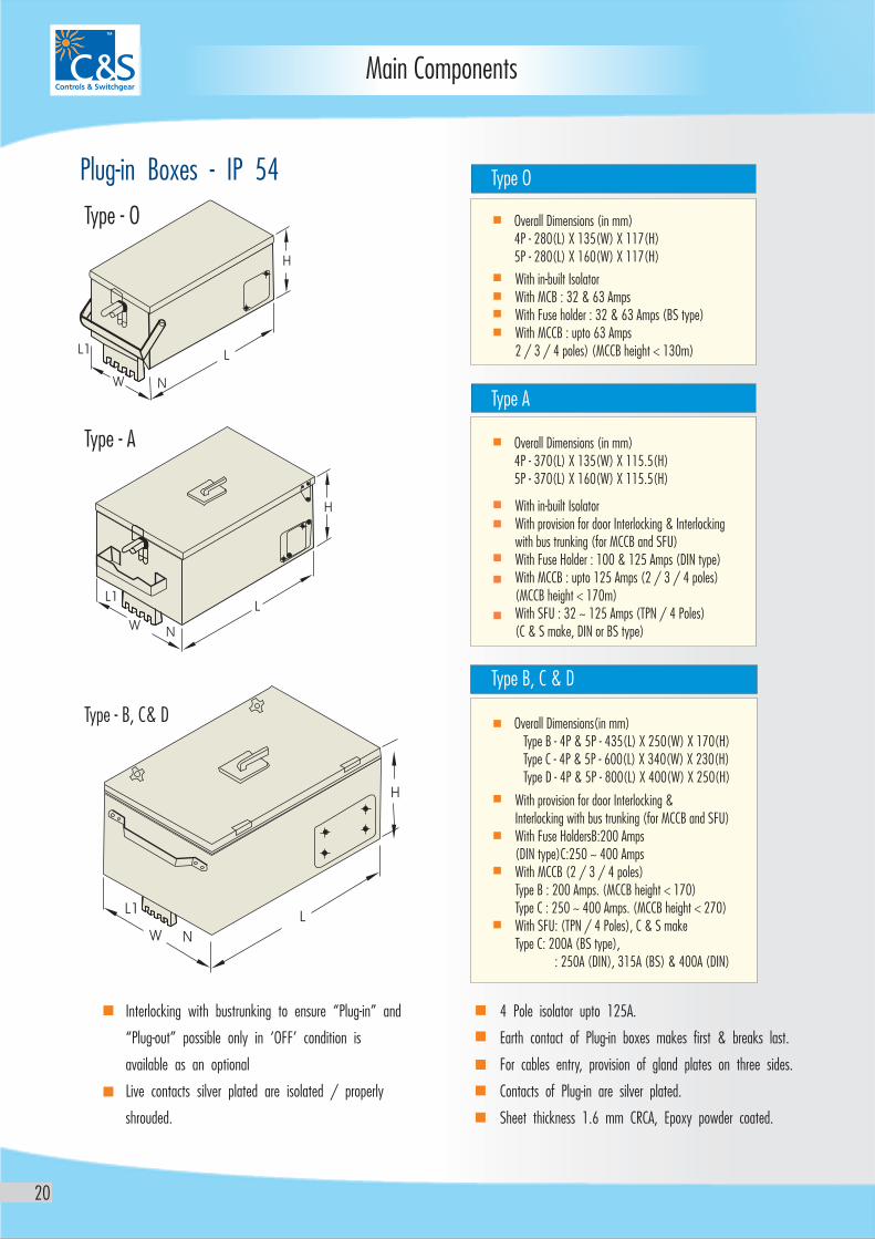
Interlocking with bustrunking to ensure “Plug-in” and
“Plug-out” possible only in ‘OFF’ condition is
available as an optional
Live contacts silver plated are isolated / properly
shrouded.
4 Pole isolator upto 125A.
Earth contact of Plug-in boxes makes first & breaks last.
For cables entry, provision of gland plates on three sides.
Contacts of Plug-in are silver plated.
Sheet thickness 1.6 mm CRCA, Epoxy powder coated.
Plug-in Boxes - IP 54
With provision for door Interlocking & Interlocking with bus trunking (for MCCB and SFU)With Fuse HoldersB:200 Amps(DIN type)C:250 ~ 400 AmpsWith MCCB (2 / 3 / 4 poles)Type B : 200 Amps. (MCCB height < 170)Type C : 250 ~ 400 Amps. (MCCB height < 270)With SFU: (TPN / 4 Poles), C & S makeType C: 200A (BS type), : 250A (DIN), 315A (BS) & 400A (DIN)
With in-built IsolatorWith MCB : 32 & 63 AmpsWith Fuse holder : 32 & 63 Amps (BS type)With MCCB : upto 63 Amps 2 / 3 / 4 poles) (MCCB height < 130m)
Overall Dimensions (in mm) 4P - 280(L) X 135(W) X 117(H)5P - 280(L) X 160(W) X 117(H)
Type B, C & D
Type O
With in-built IsolatorWith provision for door Interlocking & Interlocking with bus trunking (for MCCB and SFU)With Fuse Holder : 100 & 125 Amps (DIN type)With MCCB : upto 125 Amps (2 / 3 / 4 poles)(MCCB height < 170m)With SFU : 32 ~ 125 Amps (TPN / 4 Poles) (C & S make, DIN or BS type)
Type A
Overall Dimensions (in mm) 4P - 370(L) X 135(W) X 115.5(H)5P - 370(L) X 160(W) X 115.5(H)
Overall Dimensions(in mm) Type B - 4P & 5P - 435(L) X 250(W) X 170(H) Type C - 4P & 5P - 600(L) X 340(W) X 230(H) Type D - 4P & 5P - 800(L) X 400(W) X 250(H)
21
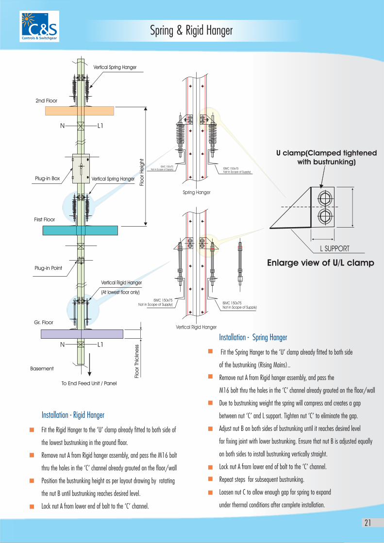
Spring & Rigid Hanger
Fit the Rigid Hanger to the ‘U’ clamp already fitted to both side of
the lowest bustrunking in the ground floor.
Remove nut A from Rigid hanger assembly, and pass the M16 bolt
thru the holes in the ‘C’ channel already grouted on the floor/wall
Position the bustrunking height as per layout drawing by rotating
the nut B until bustrunking reaches desired level.
Lock nut A from lower end of bolt to the ‘C’ channel.
Installation - Rigid Hanger
Fit the Spring Hanger to the ‘U’ clamp already fitted to both side
of the bustrunking (Rising Mains)..
Remove nut A from Rigid hanger assembly, and pass the
M16 bolt thru the holes in the ‘C’ channel already grouted on the floor/wall
Due to bustrunking weight the spring will compress and creates a gap
between nut ‘C’ and L support. Tighten nut ‘C’ to eliminate the gap.
Adjust nut B on both sides of bustrunking until it reaches desired level
for fixing joint with lower bustrunking. Ensure that nut B is adjusted equally
on both sides to install bustrunking vertically straight.
Lock nut A from lower end of bolt to the ‘C’ channel.
Repeat steps for subsequent bustrunking.
Loosen nut C to allow enough gap for spring to expand
under thermal conditions after complete installation.
Installation - Spring Hanger
Enlarge view of U/L clamp
U clamp(Clamped tightened with bustrunking)
Plug-in Box
First Floor
2nd Floor
Vertical Spring Hanger
Vertical Spring Hanger
Spring Hanger
Vertical Rigid Hanger
(At lowest floor only)
Plug-in Point
Gr. Floor
Basement
To End Feed Unit / Panel
Flo
or Th
ickn
ess
Flo
or H
eig
ht
Vertical Rigid Hanger
ISMC 150x75Not in Scope of Supply)
ISMC 150x75Not in Scope of Supply)
ISMC 150x75Not in Scope of Supply)
ISMC 150x75Not in Scope of Supply)
L SUPPORT
N
N
L1
L1
22
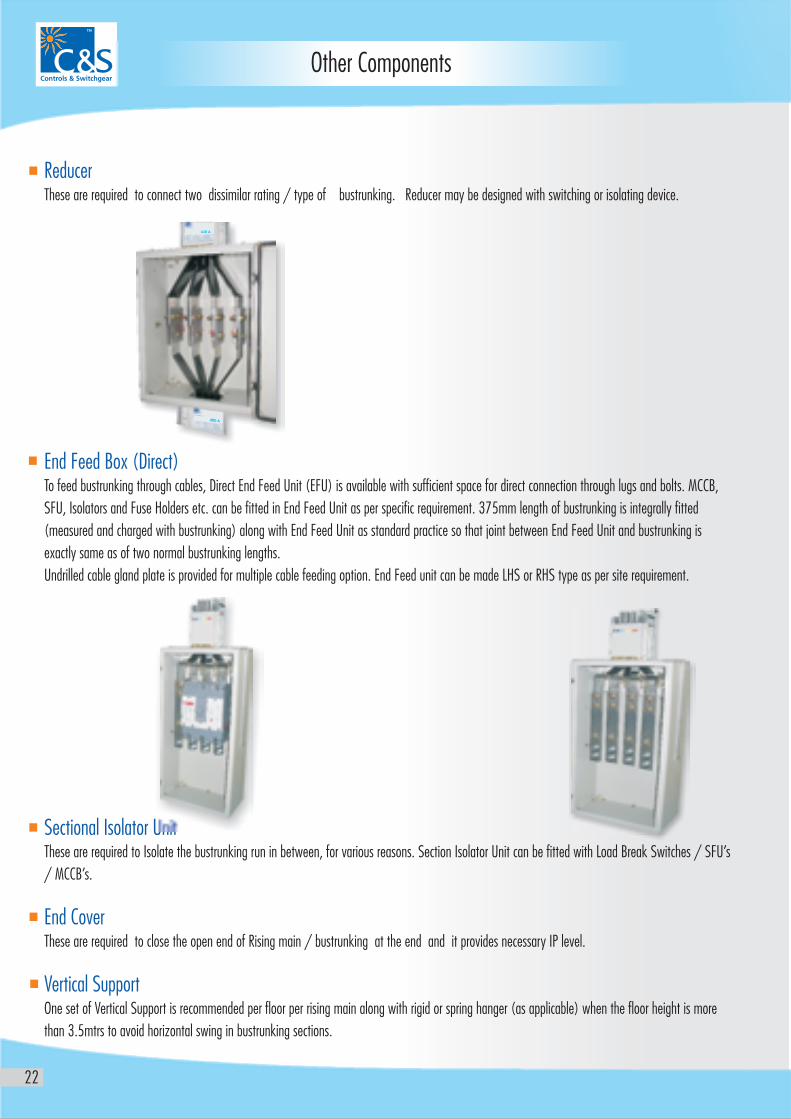
Reducer
End Feed Box (Direct)
Sectional Isolator Unit
End Cover
Vertical Support
These are required to connect two dissimilar rating / type of bustrunking. Reducer may be designed with switching or isolating device.
To feed bustrunking through cables, Direct End Feed Unit (EFU) is available with sufficient space for direct connection through lugs and bolts. MCCB,
SFU, Isolators and Fuse Holders etc. can be fitted in End Feed Unit as per specific requirement. 375mm length of bustrunking is integrally fitted
(measured and charged with bustrunking) along with End Feed Unit as standard practice so that joint between End Feed Unit and bustrunking is
exactly same as of two normal bustrunking lengths.
Undrilled cable gland plate is provided for multiple cable feeding option. End Feed unit can be made LHS or RHS type as per site requirement.
These are required to Isolate the bustrunking run in between, for various reasons. Section Isolator Unit can be fitted with Load Break Switches / SFU’s
/ MCCB’s.
These are required to close the open end of Rising main / bustrunking at the end and it provides necessary IP level.
One set of Vertical Support is recommended per floor per rising main along with rigid or spring hanger (as applicable) when the floor height is more
than 3.5mtrs to avoid horizontal swing in bustrunking sections.
Other Components
400 A
630 A
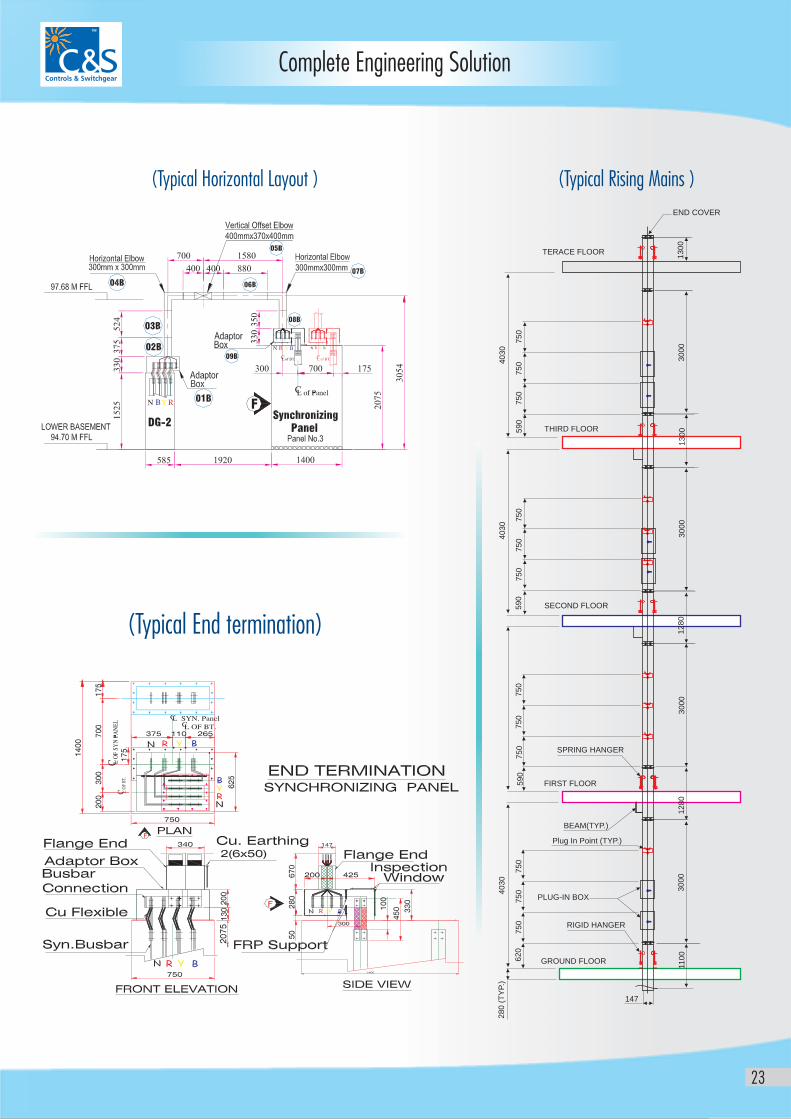
Complete Engineering Solution
23
(Typical Horizontal Layout ) (Typical Rising Mains )
(Typical End termination)
TERACE FLOOR
END COVER
GROUND FLOOR
147
28
0 (
TY
P.)
62
05
90
59
05
90
75
07
50
75
07
50
75
07
50
75
07
50
75
07
50
75
07
50
40
30
40
30
40
30
12
80
110
03
00
03
00
03
00
03
00
01
30
01
28
01
30
0
RIGID HANGER
PLUG-IN BOX
Plug In Point (TYP.)
BEAM(TYP.)
FIRST FLOOR
SECOND FLOOR
THIRD FLOOR
SPRING HANGER
24
Installation Instructions
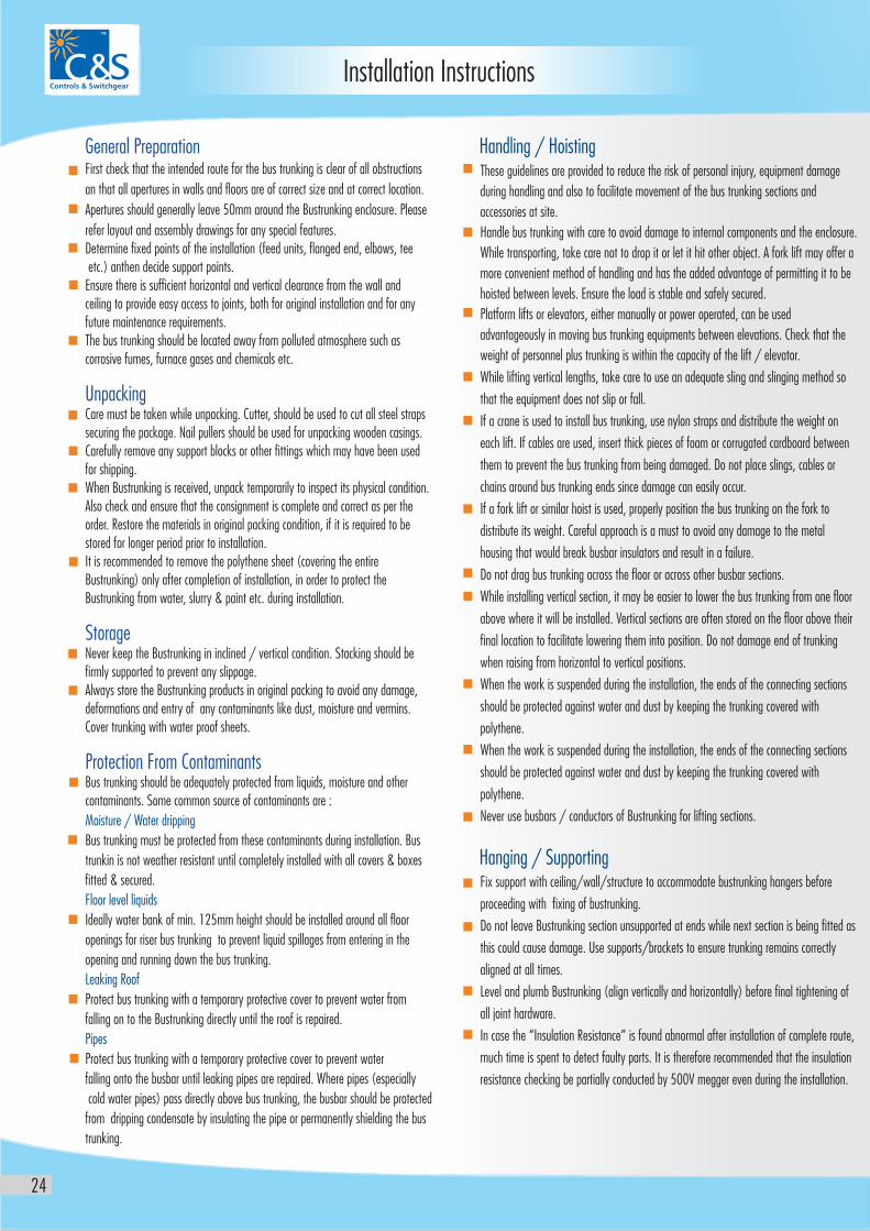
General Preparation
Unpacking
Storage
Protection From Contaminants
First check that the intended route for the bus trunking is clear of all obstructions
an that all apertures in walls and floors are of correct size and at correct location.
Apertures should generally leave 50mm around the Bustrunking enclosure. Please
refer layout and assembly drawings for any special features.
Determine fixed points of the installation (feed units, flanged end, elbows, tee
etc.) anthen decide support points.
Ensure there is sufficient horizontal and vertical clearance from the wall and
ceiling to provide easy access to joints, both for original installation and for any
future maintenance requirements.
The bus trunking should be located away from polluted atmosphere such as
corrosive fumes, furnace gases and chemicals etc.
Care must be taken while unpacking. Cutter, should be used to cut all steel straps
securing the package. Nail pullers should be used for unpacking wooden casings.
Carefully remove any support blocks or other fittings which may have been used
for shipping.
When Bustrunking is received, unpack temporarily to inspect its physical condition.
Also check and ensure that the consignment is complete and correct as per the
order. Restore the materials in original packing condition, if it is required to be
stored for longer period prior to installation.
It is recommended to remove the polythene sheet (covering the entire
Bustrunking) only after completion of installation, in order to protect the
Bustrunking from water, slurry & paint etc. during installation.
Never keep the Bustrunking in inclined / vertical condition. Stacking should be
firmly supported to prevent any slippage.
Always store the Bustrunking products in original packing to avoid any damage,
deformations and entry of any contaminants like dust, moisture and vermins.
Cover trunking with water proof sheets.
Bus trunking should be adequately protected from liquids, moisture and other
contaminants. Some common source of contaminants are :
Bus trunking must be protected from these contaminants during installation. Bus
trunkin is not weather resistant until completely installed with all covers & boxes
fitted & secured.
Ideally water bank of min. 125mm height should be installed around all floor
openings for riser bus trunking to prevent liquid spillages from entering in the
opening and running down the bus trunking.
Protect bus trunking with a temporary protective cover to prevent water from
falling on to the Bustrunking directly until the roof is repaired.
Protect bus trunking with a temporary protective cover to prevent water
falling onto the busbar until leaking pipes are repaired. Where pipes (especially
cold water pipes) pass directly above bus trunking, the busbar should be protected
from dripping condensate by insulating the pipe or permanently shielding the bus
trunking.
Moisture / Water dripping
Floor level liquids
Leaking Roof
Pipes
These guidelines are provided to reduce the risk of personal injury, equipment damage
during handling and also to facilitate movement of the bus trunking sections and
accessories at site.
Handle bus trunking with care to avoid damage to internal components and the enclosure.
While transporting, take care not to drop it or let it hit other object. A fork lift may offer a
more convenient method of handling and has the added advantage of permitting it to be
hoisted between levels. Ensure the load is stable and safely secured.
Platform lifts or elevators, either manually or power operated, can be used
advantageously in moving bus trunking equipments between elevations. Check that the
weight of personnel plus trunking is within the capacity of the lift / elevator.
While lifting vertical lengths, take care to use an adequate sling and slinging method so
that the equipment does not slip or fall.
If a crane is used to install bus trunking, use nylon straps and distribute the weight on
each lift. If cables are used, insert thick pieces of foam or corrugated cardboard between
them to prevent the bus trunking from being damaged. Do not place slings, cables or
chains around bus trunking ends since damage can easily occur.
If a fork lift or similar hoist is used, properly position the bus trunking on the fork to
distribute its weight. Careful approach is a must to avoid any damage to the metal
housing that would break busbar insulators and result in a failure.
Do not drag bus trunking across the floor or across other busbar sections.
While installing vertical section, it may be easier to lower the bus trunking from one floor
above where it will be installed. Vertical sections are often stored on the floor above their
final location to facilitate lowering them into position. Do not damage end of trunking
when raising from horizontal to vertical positions.
When the work is suspended during the installation, the ends of the connecting sections
should be protected against water and dust by keeping the trunking covered with
polythene.
When the work is suspended during the installation, the ends of the connecting sections
should be protected against water and dust by keeping the trunking covered with
polythene.
Never use busbars / conductors of Bustrunking for lifting sections.
Fix support with ceiling/wall/structure to accommodate bustrunking hangers before
proceeding with fixing of bustrunking.
Do not leave Bustrunking section unsupported at ends while next section is being fitted as
this could cause damage. Use supports/brackets to ensure trunking remains correctly
aligned at all times.
Level and plumb Bustrunking (align vertically and horizontally) before final tightening of
all joint hardware.
In case the “Insulation Resistance” is found abnormal after installation of complete route,
much time is spent to detect faulty parts. It is therefore recommended that the insulation
resistance checking be partially conducted by 500V megger even during the installation.
Handling / Hoisting
Hanging / Supporting
25
Installation Instructions
Two types of horizontal supports are available . Choose one depending upon
Edgewise installtion as shown in diagram. It is generally preferred to
install edgewise.
After hangers have been installed with tie rods (Not part of bustrunking supply),
bustrunking length may be joined starting from EFU / Flanged End.
To connect one length to the other please refer Figure-1
Horizontal support need to be tighten with hanger once the run is completed.
It is recommended to support Bustrunking at intervals of around 1.5 meters
(1.0mtr minimum & 2 meters maximum) depending upon following points:
Shape, strength, rigidness and distance of hangers from ceiling / wall.
Rating (Low/high) and numbers of plug-in boxes to be fitted between two brackets.
Ensure each element of Bustrunking run is supported by at least one bracket.
As far as possible avoid fixing of bracket at Bustrunking joint area and at plug-in point
window.
Minimum distance between two Bustrunking will increase if plug-in box/end fe ed
unit/reducer etc. is fitted in any of the straight run. 100mm clearance need to be
considered between two boxes / unit installed on parallel runs. Space required for
door opening should also be considered. 100mm min. clearance should be considered
in case of trunking running close to beam / columns / pillars
Spacing between two brackets
Horizontal installation
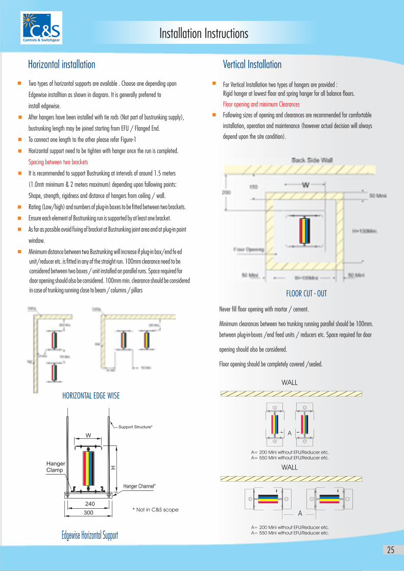
For Vertical Installation two types of hangers are provided :
Rigid hanger at lowest floor and spring hanger for all balance floors.
Following sizes of opening and clearances are recommended for comfortable
installation, operation and maintenance (however actual decision will always
depend upon the site condition).
Floor opening and minimum Clearances
Vertical Installation
Never fill floor opening with mortar / cement.
Minimum clearances between two trunking running parallel should be 100mm.
between plug-in-boxes /end feed units / reducers etc. Space required for door
opening should also be considered.
Floor opening should be completely covered /sealed.
FLOOR CUT - OUT
HORIZONTAL EDGE WISE
A
A
WALL
WALL
A= 200 Mini without EFU/Reducer etc.A= 550 Mini without EFU/Reducer etc.
A= 200 Mini without EFU/Reducer etc.A= 550 Mini without EFU/Reducer etc.
* Not in C&S scope
26
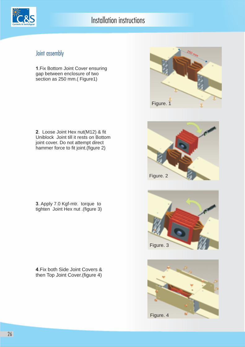
Joint assembly
1.Fix Bottom Joint Cover ensuring gap between enclosure of two section as 250 mm.( Figure1)
2. Loose Joint Hex nut(M12) & fit Uniblock Joint till it rests on Bottom joint cover. Do not attempt direct hammer force to fit joint.(figure 2)
3. Apply 7.0 Kgf-mtr. torque to tighten Joint Hex nut .(figure 3)
4.Fix both Side Joint Covers & then Top Joint Cover.(figure 4)
Figure. 4
Figure. 1
Figure. 3
Figure. 2
Installation instructions
27
Installation Instructions
Earthing
Inspection & Testing
Bond the internal / external earthing busbars of bustrunking to main earthing ofsystem with adequate busbars or cable links as per standards and electrical regulations.
For bustrunking with internal earth, continuity is maintained through joints. Andfor bustrunking with external earth continuity is maintained through external links. Plug-in-boxes have integral earth clip which makes automatic contact while plugging the box on to the bustrunking.
Inspection after installation
Before energizing check:(a) Whether the bus trunking is not damaged.
(b) Whether the connecting parts are fixed precisely.
(c) Whether the bolt connecting the equipment are securely fastened.
(d) Whether the hangers are supporting the bus trunking securely.
(e) Whether all the joint covers and tap off outlet covers of bus trunkingare closed.
(f) Whether all busbar joints are tightened to the recommended torque.
(g) Whether end covers are fitted to the end of all runs.
Thereafter INSULATION RESISTANCE of complete installation (Run wise) shall be checked after disconnecting all equipments either by opening theisolator switch or setting the breakers in ‘OFF’ position. The insulationresistance value can not be specified due to the difference of the length ofrun / route and the environmental condition, but if it is a driedatmosphere, normally it shows a value above 100Mega ohms (500Vmegger).
In case it is below 10Mega ohms it has to be checked as it is most likelythat there may exist some factors which are reducing the insulation. Megger value of bustrunking section individually can be carried out byisolating joint assembly to locate the fault.
Reason for low insulation value can be due to above mentioned (a) to (g) factors, presence of moisture /contaminants or breakage of jointinsulators Defective section may be put to hot blowing air for drying themoisture and improving megger value.
If the insulation value does not improve, contact the C&S.
Periodic checking
Summary
Even though the system is virtually maintenance free following checks are recommended (for guaranteeing safe usage of the bustrunking for a longtime) preferably once in a year.
Check to ensure there is no deformation, damage, dust etc. through out the whole length of the bus trunking and there is no dislocation,bending and other abnormality of the connecting covers, hangers anplug-in- boxes.
Environment where the bus trunking is used sometimes changes afterits installation. Check that the environment is not hazardous evenpartially due to water, moisture, high temperature, corrosive gas,immoderate vibration, dust etc.
Since the spring washers are employed in busbar joints, there shall beno problem of joint loosening. Therefore, periodical check is notnecessary if recommended torque is applied to the joint clampassembly during installation. However it is advisable to re-check thetightening after full loading of bustrunking for 24 hou
Check and ensure that total load is not exceeding the capacity of bustrunking. Especially, pay attention when the main line is branchedby elbows, tee’s or crosses.
Highly insulating, non-hygroscopic Insulation material are used forbusbars, hence IR value should not reduce at later stage. Still it isadvisable to check IR value by megger (500V) periodically.
Review all layout drawings and other technical details very carefully.
Check description and identification of each piece before installing it.
Follow the joint assembly instructions.
Check insulation resistance while fixing sections of bustrunking during installation.
Check for possible source of contaminants that may fall on the bus trunkingduring installation and take preventive actions.
(a) Check the external appearances
(b) Environmental check
(c) Check the joint connections
(d) Check the load condition
(e) Check the insulation resistance (IR)
28
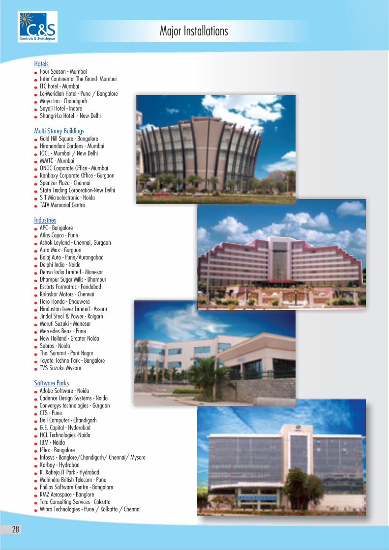
Major Installations
Hotels
Multi Storey Buildings
Industries
Software Parks
n
n
n
n
n
n
n
n
n
n
n
n
n
n
n
n
n
n
n
n
n
n
n
n
n
n
n
n
n
n
n
n
n
n
n
n
n
n
n
n
n
n
n
n
n
n
n
n
n
n
n
n
n
n
Four Season - Mumbai Inter Continental The Grand- Mumbai ITC hotel - Mumbai Le-Meridian Hotel - Pune / Bangalore Maya Inn - Chandigarh Sayaji Hotel - Indore Shangri-La Hotel - New Delhi
Gold Hill Sqaure - Bangalore Hiranandani Gardens - Mumbai IOCL - Mumbai / New Delhi MMTC - Mumbai ONGC Corporate Office - Mumbai Ranbaxy Corporate Office - Gurgaon Spenzer Plaza - Chennai State Trading Corporation-New Delhi S T Microelectronic - Noida TATA Memorial Centre
APC - Bangalore Atlas Copco - Pune Ashok Leyland - Chennai, Gurgaon Auto Max - Gurgaon Bajaj Auto - Pune/Aurangabad Delphi India - Noida Denso India Limited - Manesar Dhampur Sugar Mills - Dhampur Escorts Farmatrac - Faridabad Kirloskar Motors - Chennai Hero Honda - Dhauwera Hindustan Lever Limited - Assam Jindal Steel & Power - Raigarh Maruti Suzuki - Manesar Mercedes Benz - Pune New Holland - Greater Noida Subros - Noida Thai Summit - Pant Nagar Toyota Techno Park - Bangalore TVS Suzuki- Mysore
Adobe Software - Noida Cadence Design Systems - Noida Convergys technologies - Gurgaon CTS - Pune Dell Computer - Chandigarh G.E. Capital - Hyderabad HCL Technologies -Noida IBM - Noida IFlex - Bangalore Infosys - Banglore/Chandigarh/ Chennai/ Mysore Karbay - Hydrabad K. Raheja IT Park - Hydrabad Mahindra British Telecom - Pune Philips Software Centre - Bangalore RMZ Aerospace - Banglore Tata Consulting Services - Calcutta Wipro Technologies - Pune / Kolkatta / Chennai
29
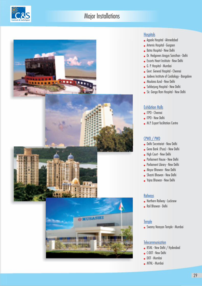
Major Installations
Hospitals
Exhibition Halls
CPWD / PWD
Railways
Temple
Telecommunication
n
n
n
n
n
n
n
n
n
n
n
n
n
n
n
n
n
n
n
n
n
n
n
n
n
n
n
n
n
medabad
Dr. Hedgavers Arogya Sansthan - Delhi
Govt. General Hospital - Chennai
Maulana Azad - New Delhi
Safdarjung Hospital - New Delhi
Sir. Ganga Ram Hospital - New Delhi
ITPO - Chennai
ITPO - New Delhi
M.P. Export facilitation Centre
Delhi Secretariat - New Delhi
Gene Bank (Pusa) - New Delhi
High Court - New Delhi
Parliament House - New Delhi
Parliament Library - New Delhi
Northern Railway - Lucknow
Rail Bhawan - Delhi
Swamy Narayan Temple - Mumbai
BSNL - New Delhi / Hyderabad
C-DOT - New Delhi
DOT - Mumbai
MTNL - Mumbai
Appolo Hospital - Ah
Artemis Hospital - Gurgaon
Batra Hospital - New Delhi
Escorts Heart Institute - New Delhi
G. P. Hospital - Mumbai
Jaideva Institute of Cardiology - Bangalore
Mayur Bhawan - New Delhi
Shastri Bhawan - New Delhi
Yojna Bhawan - New Delhi
Major Export Orders
1. KYCR Coil Industries - Bangladesh
2. Dafna Tower - Doha
3. Doha Tower - Doha
4. 81 flats at AI-Sadd - Doha
5. B+G+5 Flats - Doha
6. B+G+6 Flats - Doha
7. G+11 Building - Doha
8. Westbay 44 Tower - Doha
9. Shk Falak Twin Tower - Doha
10. Mellineium Tower - Doha
11. Mushreif Tower - Doha
12. Port Saeed - Dubai
13. Evershine Trading - Dubai
14. Baiji Power Plant - IRAQ
15. LDPE Project Bandar Imam - Iran
16. P.T. Indo - Bharat Rayon - Indonensia
17. Magadi Soda plant - Kenya
18. AL Nazzar Tower - Jordan / Kuwait
19. Al Mazaya Tower - Kuwait
20. Kuwait National Petroleum Corporation - Kuwait
21. Kirby Building System - Kuwait
22. Holiday Inn - Kuwait
23. P.T Prakasa Heavyndo - Malaysia
24. Cyber Tower, Ebene city - Mauritius
25. Rusail Power Project - Oman
26. Haima West Power station - Oman
27. Salalah Power Project -Oman
28. OMIFCO -Oman
29. E-Services - Manila, Philipines
30. P.S Bank - Philipines
31. Victoria Tower - Philipines
32. Alstom - South Africa
230
Mission & Quality policy
31
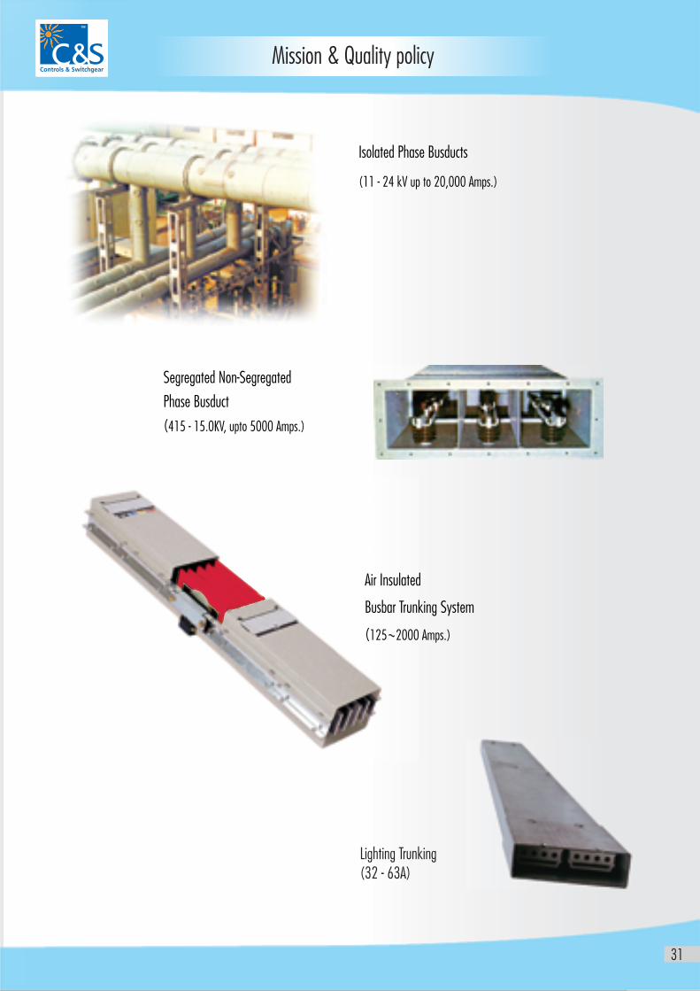
Air Insulated
Busbar Trunking System
(125 2000 Amps.)
Segregated Non-Segregated
Phase Busduct
(415 - 15.0KV, upto 5000 Amps.)
Isolated Phase Busducts
(11 - 24 kV up to 20,000 Amps.)
Lighting Trunking (32 - 63A)


![Bus Bar Protection[1]](https://img.pdfslide.us/doc/110x75/552bd47e4a7959eb7c8b45d0/bus-bar-protection1.jpg)
