Embed Size (px)
Citation preview

Building a WAN
TDJ3M7
Northview Heights
Mr. Zaheer Bhyat

2
IntroductionThe following slides offer a presentation identifying the steps necessary for designing a simple Wide Area Network, including:
•A schematic diagram of the network
•An IP addressing structure
•Media connections
•Router configuration
•Establishing connectivity, and
•Troubleshooting

3
Premise
A small company with three locations in different cities requires Wide Area Network connectivity
The company requires:
• 7 Subnetworks
• a minimum of 20 Hosts per subnet
The company has been given a Class B IP Address:
• 169.50.0.0

4
ProcedureThe following slides will identify the sequence of steps necessary to meet the requirements of the client.
• Network configuration/schematic
• IP Addressing structure
• Subnet addressing
• Subnet masks
• Interface addressing
• Usable host addressing
• Physical device connections
• Router configuration
• Configuration modes
•Configure Hostnames
Setting Passwords
•Configure routing protocols
• Configure Interfaces
• Configure Routing Tables
• Configure Console Terminal
• Save configuration
• Test Connectivity
•Telnet
•Ping
• Troubleshooting
• Physical
• Logical

5
Network Schematic
Toronto
New York
London
Console Terminal Console Terminal
6
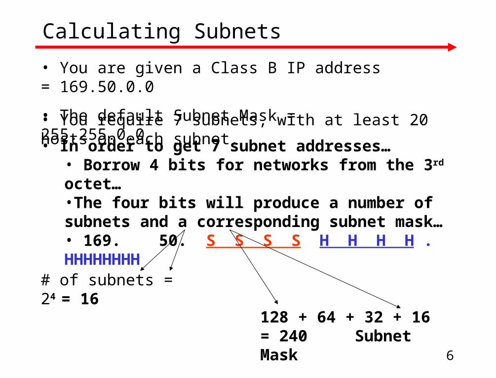
Calculating Subnets
• In order to get 7 subnet addresses… • Borrow 4 bits for networks from the 3rd octet…•The four bits will produce a number of subnets and a corresponding subnet mask…• 169. 50. S S S S H H H H . HHHHHHHH
• You are given a Class B IP address = 169.50.0.0
• The default Subnet Mask = 255.255.0.0
• You require 7 subnets, with at least 20 hosts on each subnet.
128 + 64 + 32 + 16 = 240 Subnet Mask
# of subnets = 24 = 16

7
Calculate subnet address range
Note:• 8 bit octet: value = 256 - 128 64 32 16 8 4 2 1 (0-255)• 4 bits borrowed: value = 240 - 128 64 32 16• Subnet range limit = 16• Network ID 169.50. 0 – 15 .0 0000 0000 - 0000 1111
169.50. 16 – 31 .0 0001 0000 - 0001 1111 169.50. 32 – 47 .0 0010 0000 - 0010 1111 169.50. 48 - 63 .0 0011 0000 - 0011 1111 169.50. 64 - 79 .0 0100 0000 - 0100 1111 169.50. 80 - 95 .0 0101 0000 - 0101 1111 169.50. 96 - 111 .0 0110 0000 - 0110 1111
169.50. 112 - 127 .0 0111 0000 - 0111 1111 169.50. 128 - 143 .0 1000 0000 - 1000 1111 169.50. 144 - 159 .0 1001 0000 - 1001 1111 169.50. 160 - 175 .0 1010 0000 - 1010 1111 169.50. 176 - 191 .0 1011 0000 - 1011 1111 169.50. 192 - 207 .0 1100 0000 - 1100 1111
169.50. 208 - 223 .0 1101 0000 - 1101 1111 169.50. 224 - 239 .0 1110 0000 - 1110 1111
8
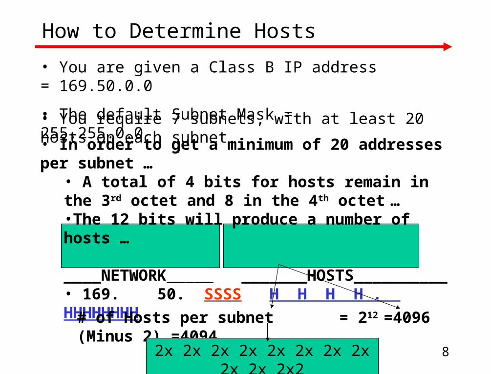
How to Determine Hosts
• In order to get a minimum of 20 addresses per subnet … • A total of 4 bits for hosts remain in the 3rd octet and 8 in the 4th octet …•The 12 bits will produce a number of hosts …
____NETWORK_____ _______HOSTS__________• 169. 50. SSSS H H H H . HHHHHHHH
• You are given a Class B IP address = 169.50.0.0
• The default Subnet Mask = 255.255.0.0
• You require 7 subnets, with at least 20 hosts on each subnet.
# of Hosts per subnet = 212 =4096 (Minus 2) =4094
2x 2x 2x 2x 2x 2x 2x 2x 2x 2x 2x2

9
Calculate usable host address range
Subnet #
#
1
2
3
4
5
6
7
8
9
10
11
12
13
14
Subnet IP
ID
169.50.16.0
169.50.32.0
169.50.48.0
169.50.64.0
169.50.80.0
169.50.96.0
169.50.112.0
169.50.128.0
169.50.144.0
169.50.160.0
169.50.176.0
169.50.192.0
169.50.208.0
169.50.224.0
# of Hosts per subnet = 212 =4096 (Minus 2) =4094
Host addresses per subnet
Range
169.50.16.1 - 169.50.31.254
169.50.32.1 - 169.50.47.254
169.50.48.1 - 169.50.63.254
169.50.64.1 - 169.50.79.254
169.50.80.1 - 169.50.95.254
169.50.96.1 - 169.50.111.254
169.50.112.1 - 169.50.127.254
169.50.128.1 - 169.50.143.254
169.50.144.1 - 169.50.159.254
169.50.160.1 - 169.50.175.254
169.50.176.1 - 169.50.191.254
169.50.192.1 - 169.50.207.254
169.50.208.1 - 169.50.223.254
169.50.224.1 - 169.50.239.254

10
Identify Subnets and Interfaces
Toronto
New York
London
S1
SO
E0
SO
SO
S1
S1
E0
E1
Console Terminal Console Terminal
E0
Subnet #1
Subnet #7
Subnet #6
Subnet #5
Subnet #4
Subnet #3Subnet #2
1 2 3 4 5 6
7 8 9 101112
AB
12x
6x
8x
2x
9x
3x
10x
4x
11x
5x
7x
1x
Eth
ern
et
A
12x
6x
8x
2x
9x
3x
10x
4x
11x
5x
7x
1x
C
12
34
56
78
9101
112
AB
12x
6x
8x
2x
9x
3x
10x
4x
11x
5x
7x
1x
E th er ne t
A
12x
6x
8x
2x
9x
3x
10x
4x
11x
5x
7x
1x
C
1 2 3 4 5 6
7 8 9 101112
AB
12x
6x
8x
2x
9x
3x
10x
4x
11x
5x
7x
1x
Eth
ern
et
A
12x
6x
8x
2x
9x
3x
10x
4x
11x
5x
7x
1x
C
1 2 3 4 5 6
7 8 9 101112
AB
12x
6x
8x
2x
9x
3x
10x
4x
11x
5x
7x
1x
Eth
ern
et
A
12x
6x
8x
2x
9x
3x
10x
4x
11x
5x
7x
1x
C
11
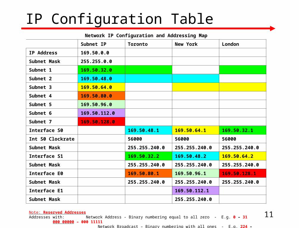
IP Configuration TableNetwork IP Configuration and Addressing Map
Subnet IP Toronto New York London
IP Address 169.50.0.0
Subnet Mask 255.255.0.0
Subnet 1 169.50.32.0
Subnet 2 169.50.48.0
Subnet 3 169.50.64.0
Subnet 4 169.50.80.0
Subnet 5 169.50.96.0
Subnet 6 169.50.112.0
Subnet 7 169.50.128.0
Interface S0 169.50.48.1 169.50.64.1 169.50.32.1
Int S0 Clockrate 56000 56000 56000
Subnet Mask 255.255.240.0 255.255.240.0 255.255.240.0
Interface S1 169.50.32.2 169.50.48.2 169.50.64.2
Subnet Mask 255.255.240.0 255.255.240.0 255.255.240.0
Interface E0 169.50.80.1 169.50.96.1 169.50.128.1
Subnet Mask 255.255.240.0 255.255.240.0 255.255.240.0
Interface E1 169.50.112.1
Subnet Mask 255.255.240.0
Note: Reserved AddressesAddresses with: Network Address - Binary numbering equal to all zero - E.g. 0 – 31 000 00000 – 000 11111 Network Broadcast – Binary numbering with all ones - E.g. 224 – 255 111 00000 – 111 11111

12
Assign Network IP Configuration
Toronto
New York
London
S1 - 32.2
SO - 48.1
E0 - 80.1
SO 64.1
SO - 32.1
S1 64.2
S1 - 48.2
E0 - 128.1
E1 - 112.1
Console Terminal Console Terminal
E0 - 96.1
Subnet #1 -169.50.32.0
Subnet #7 - 169.50.128.0
Subnet #6 - 169.50.112.0
Subnet #5 -169.50.96.0
Subnet #4 - 169.50.80.0
Subnet #3 - 169.50.64.0
Subnet #2 - 169.50.48.0
1 2 3 4 5 6
7 8 9 101112
AB
12x
6x
8x
2x
9x
3x
10x
4x
11x
5x
7x
1x
Eth
ern
et
A
12x
6x
8x
2x
9x
3x
10x
4x
11x
5x
7x
1x
C
12
34
56
78
9101
112
AB
12x
6x
8x
2x
9x
3x
10x
4x
11x
5x
7x
1x
E th er ne t
A
12x
6x
8x
2x
9x
3x
10x
4x
11x
5x
7x
1x
C
1 2 3 4 5 6
7 8 9 101112
AB
12x
6x
8x
2x
9x
3x
10x
4x
11x
5x
7x
1x
Eth
ern
et
A
12x
6x
8x
2x
9x
3x
10x
4x
11x
5x
7x
1x
C
1 2 3 4 5 6
7 8 9 101112
AB
12x
6x
8x
2x
9x
3x
10x
4x
11x
5x
7x
1x
Eth
ern
et
A
12x
6x
8x
2x
9x
3x
10x
4x
11x
5x
7x
1x
C
13
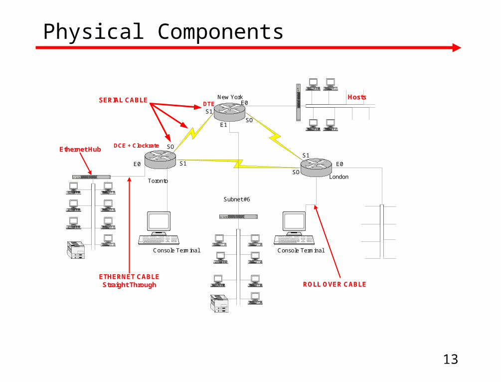
Physical Components
SERIAL CABLE
Toronto
New York
London
S1
SO
E0
SO
SO
S1
S1
E0
E1
Console Terminal Console Terminal
E0
Subnet #6
1 2 3 4 5 6
7 8 9 101112
AB
12x
6x
8x
2x
9x
3x
10x
4x
11x
5x
7x
1x
Eth
ern
et
A
12x
6x
8x
2x
9x
3x
10x
4x
11x
5x
7x
1x
C
12
34
56
78
9101112
AB
12x
6x
8x2x
9x3x
10x
4x
11x
5x
7x1x
Et her net
A
12x
6x
8x2x
9x
3x
10x
4x
11x
5x
7x1x
C
1 2 3 4 5 6
7 8 9101112
AB
12x
6x
8x
2x
9x
3x
10x
4x
11x
5x
7x
1x
Eth
ern
et
A
12x
6x
8x
2x
9x
3x
10x
4x
11x
5x
7x
1x
C
DTE
DCE + Clockrate
ETHERNET CABLEStraight Through ROLL OVER CABLE
Ethernet Hub
Hosts

14
Router Configuration
Access Hyperterminal from the Console Terminal
Configure Com Port settings as indicated
15
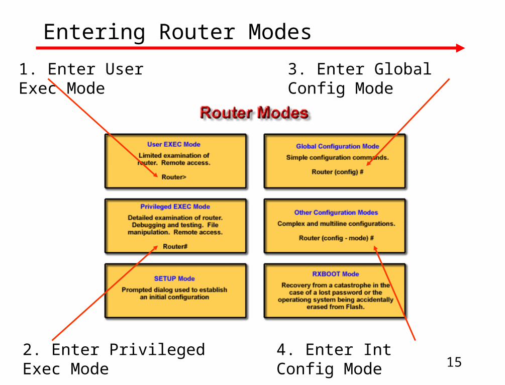
Entering Router Modes
1. Enter User Exec Mode
2. Enter Privileged Exec Mode
3. Enter Global Config Mode
4. Enter Int Config Mode

16
Router Configuration Commands …
•Enable Global Config Mode•Configure Terminal•Configure Hostname •Set Secret password•Routing Protocol – (Hop Count Metric limit 15 – good for small WANs)
•Configure Serial Interface
•Set Clockrate @ DCE connection
•Configure Serial Interface
•Configure Ethernet Interface
EnableConfigure terminalHostname TorontoEnable secret classRouter ripNetwork 169.50.32.0Network 169.50.48.0Network 169.50.64.0Int S0Ip address 169.50.48.1 255.255.240.0Clockrate 56000 No shutInt S1Ip address 169.50.32.2 255.255.240.0No shutInt E0Ip address 169.50.80.1 255.255.240.0No shut

17
Router Configuration Commands
Line con 0Password ciscoLoginLine vty 0 4Password ciscoLoginExitIp host Toronto 169.50.48.1 169.50.32.2 169.50.80.1Ip host New York 169.50.64.1 169.50.48.2 169.50.96.1 169.50.112.1Ip host London 169.50.32.1 169.50.64.2 169.50.128.1ExitExitCopy run start
•Configure Line console for remote/telnet access and set login passwords
•Configure Routing Table
•Exit
•Save configuration

18
Testing Connectivity
Basic Network Testing include the following commands:•telnet•Ping•Trace•Show ip route•Show interfaces, and•debug
19
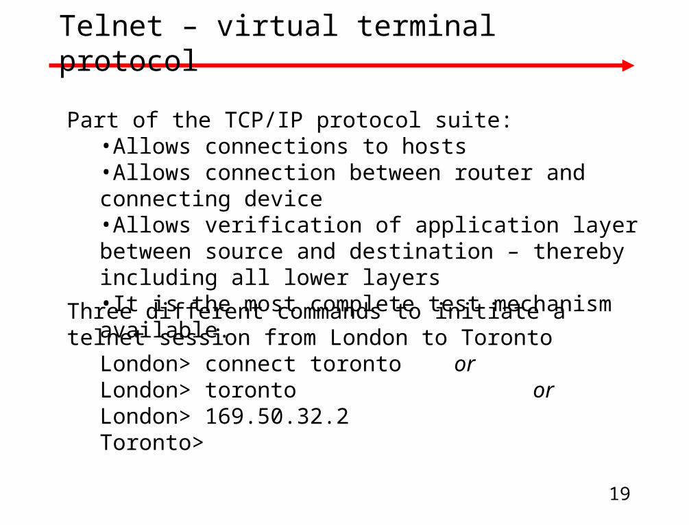
Telnet – virtual terminal protocol
Part of the TCP/IP protocol suite:•Allows connections to hosts•Allows connection between router and connecting device•Allows verification of application layer between source and destination – thereby including all lower layers•It is the most complete test mechanism available.
Three different commands to initiate a telnet session from London to Toronto
London> connect toronto orLondon> toronto orLondon> 169.50.32.2Toronto>

20
Ping – Packet Internet groper
An ICMP (Internet Control Message Protocol) echo message and its reply:
•Echo protocols are used to test whether protocols are being routed•The ping command sends a packet to the destination host and then waits for a reply packet from that host•Tests end-to-end connectivity•Echo results help to:
•Evaluate path-to-host reliability•Identify delays over the path•Determine whether the host can be reached or is functioning
Router> ping 172.16.1.5Type escape sequence to abortSending 5, 100 byte ICMP Echos to 172.16.1.5, timeout is 2 seconds:! ! ! ! !Success rate is 100 percent, round-trip min/avg/max – 1/3/4 msRouter>

21
Show interfaces serial
Show interfaces serial shows a serial connection between two router interfaces
•Interface has hardware and software pieces•Hardware includes cables, connectors, and interfaces•Software is responsible for messages such as keepalive, control and user information
•Testing physical and data link layers include checking for: •Carrier detect signal•Physical connection status•Keepalive messages being received•Data packet transmission across physical link
Router# show int s1Serial is up, line protocol is up
Hardware is cxBus SerialDescription. 56Kb San Jose - MP
Carrier detect (line status)
Keepalives
Serial 1 is up, line protocol is up OperationalSerial 1 is up, line protocol is down Connection problemsSerial 1 is down, line protocol is down Interface problemSerial 1 is administratively down, line protocol is down Disabled

22
Trace - traceroute
A program that traces the path a packet takes to a destination•Used to debug routing problems between hosts.•Trace tests each step along the way•Traces takes advantage of error messages generated by routers when a packet exceeds its Time To Live (TTL) or hop count value.•Trace sends incrementing ping echos and displays round-trip for each. Each successive gets closer to the destination•Trace identifies which router was the last reached – allowing for fault isolation
York# trace RomeType escape to abortTracing the route to Rome (172.16.33.5)
1 London (172.16.12.3) 8 msec 8 msec 8 msec2 Paris (172.16.16.2) 8 msec 8 msec 8 msec3 Rome (172.16.35.5) 8 msec 8 msec 4 msec

23
Show ip route
Show ip route displays the routing table• Table contains directions that the router uses to determine how it will direct traffic across the network• It is used to determine whether a routing table entry exists for the target network
Paris# show ip routeCode: I – IGRP derived, R – derived, O – OSPF derived
C – Connected, S – static, E – EGP derived, B – BGP derivedI – IS – IS derived, D – EIGRP derived* - candidate default route, IA – OSPF inter area routeE1 – OSPF external type 1 route, E2 – OSPF external type 2 routeL1 - IS – IS level 1 route, L2 - IS – IS level 2 routeEI – EIGRP external route
Gateway of last resort is not set
I 144.253.0.0 [100/1300] via 133.3.2.0 0:00:22 Ethernet131.108.0.0 is subnetted (mask is 255.255.255.0), 3 subnets
I 131.108.33.0 [100/180771] via 131.108.16.2, 0:01:29, EthernetC 131.108.12.0 is directly connected , Ethernet1C 131.108.16.0 is directly connected , Ethernet0I 219.100.103.0 [100/1200] via 133.3.32.2 0:00:22 Ethernet
Below Rome (131.108.33.0) is reachable by Paris (131.108.16.2) via the Ethernet1 interface

24
General model for troubleshooting
Step 1. Define the problem. What are the symptoms and the possible causes?
Step 2. Gather the facts. Isolate the possible causes.
Step 3. Consider the possibilities. Based on the gathered facts, narrow the focus relevant to the specific problem.
Step 4. Create an action plan. Devise a plan in which you manipulate only one variable at a time
Step 5. Implement the action plan. Perform each step carefully while testing to see if the symptom disappears
Step 6. Observe the results. Determine if the you resolved the problem, if yes stop the process, if no…
Step 7. Repeat the process. Return to Step 4.

25
Network Troubleshooting
Effective Troubleshooting is facilitated by keeping excellent documentation:
• Hardware or physical problems may be addressed visually and by using appropriate tools•Software problems may addressed by using software detection (IOS) tools including ping, trace ip route, telnet, and show arp
Throughout this 2nd semester you use the same basic configuration for your labs and simulations.
•For these troubleshooting labs, you can refer to this configuration and imagine what could go wrong with it, in terms of the OSI layers. - Examples of problems in each layer might include
•Layer 1 - incorrect cable used •Layer 2 - interface not configured for Ethernet •Layer 3 - subnet mask is incorrect

26
Layer 1 Errors
Layer 1 errors include:• broken cables • disconnected cables • cables connected to the wrong ports • intermittent cable connection • wrong cables used for the task at hand (must use rollovers, cross-connects, and straight-through cables correctly) • transceiver problems • DCE cable problems • DTE cable problems • devices turned off

27
Layer 2 errors
Layer 2 errors include:• improperly configured serial interfaces• improperly configured Ethernet interfaces • improper encapsulation set (HDLC is default for serial interfaces) •improper clockrate settings on serial interfaces
28
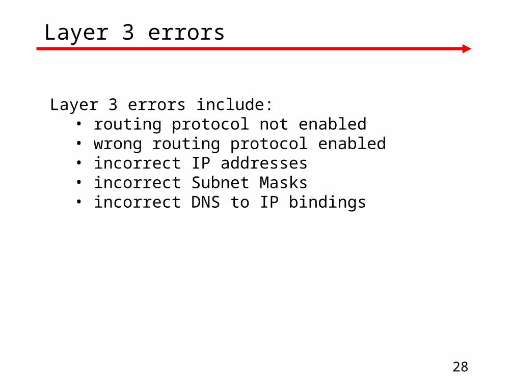
Layer 3 errors
Layer 3 errors include:• routing protocol not enabled • wrong routing protocol enabled • incorrect IP addresses • incorrect Subnet Masks • incorrect DNS to IP bindings

29
Possible induced network problems…
# Category Symptom Possible Problems Solution
1 Router Can't get from user to exec mode
Unknown enable password
Perform password recovery procedure
2 Router Ping consistently fails on 1 interface
Wrong IP address or mask entered on 1 end of the ping
While in interface mode properly configure ip address
3 Router Ping test consistently fails on 1 interface
Interface is shut down
Use no shutdown on that interface
4 Router Can't ping across a serial line
Clock rate not set on DCE end
Set clock rate on DCE end
5 Router Can't ping across serial line
Clock rate is set on both DCE and DTE ends
Clock rate should only be set on DCE end
6 Router
Typing router's name doesn't substitute for it's IP address; connection timed out
Bad DNS entry Use ip host command to fix IP address
7 Router Router won't boot into user mode
Config register has been changed
Change config register to 0x2102

30
Possible induced network problem…
8 Router Router has blank configuration file even when you show start
No configuration in NVRAM
Either in setup mode or line by line create a router config
9 Router Wrong or empty routing table
Wrong routing protocol enabled
Change routing protocol with router rip command
10 Router Wrong or empty routing table
Wrong or missing networks when routing protocol was enabled
Issue a proper router rip and network command
11 Router Router won't even begin boot process
Router power unplugged or power supply has a problem
Plug in the router
12 Router Router is running a limited IOS
No IOS image in flash or on tftp server
Find a source for the IOS image and copy into flash
13 Router Can telnet to a router but can't get past its password
You have an incorrect vty password
Go to the router in question and look up the vty password in its configuration file
14 Workstation Can't console into router
Wrong settings on terminal emulation program
Enter correct settings for terminal emulation program

31
Possible induced network problem
15 Workstations
Workstation cannot link to routers and routers and workstations seem properly configured
No power to hubs or cable may be plugged into hub's uplink port
Supply power to the hubs or move cable
16 Workstation Can't ping or telnet to the desired workstation
Incorrect TCP/IP settings on one of the workstations
Correct the TCP/IP settings on the workstation with the problem
17 Transceiver No link light on Ethernet AUI connections
Transceiver is improperly seated in the sliding latch connector or wrong cable type
Properly seat the transceiver or replace cable with a straight-through
18 Cabling Can't ping even though everything else seems OK
Cable unplugged broken or discontinuous somewhere Isolate the bad cable and replace it
19 Cabling Can't ping even though everything seems OK with devices
Wrong cable used somewhere. This lab setup requires straight-through
cross-connect and rollover cables and they are sometimes confused for each other Make sure the right cable is used for every connection

32
Conclusion
This presentation offered a step-by-step process necessary for creating a simple Wide Area Network, including:
– A schematic diagram of the network
– An IP addressing structure
– Media connections
– Router configuration
– Establishing connectivity, and
– Troubleshooting
• It is vital to note the importance of:
– Careful planning
– Good documentation
– Systematic approach
– Logical thinking.