Embed Size (px)
Citation preview
Bridgelux Vero® SE Series Array Design Guide AN120 Rev A (3/23/17) © 2017 Bridgelux, Inc. All rights reserved. Product specifications are subject to change without notice.
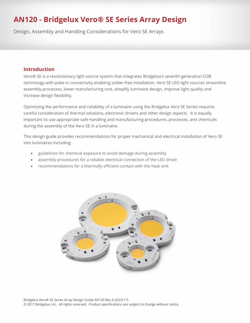
Introduction Vero® SE is a revolutionary light source system that integrates Bridgelux’s seventh generation COB technology with poke-in connectivity enabling solder-free installation. Vero SE LED light sources streamline assembly processes, lower manufacturing cost, simplify luminaire design, improve light quality and increase design flexibility.
Optimizing the performance and reliability of a luminaire using the Bridgelux Vero SE Series requires careful consideration of thermal solutions, electronic drivers and other design aspects. It is equally important to use appropriate safe-handling and manufacturing procedures, processes, and chemicals during the assembly of the Vero SE in a luminaire.
This design guide provides recommendations for proper mechanical and electrical installation of Vero SE into luminaires including:
• guidelines for chemical exposure to avoid damage during assembly • assembly procedures for a reliable electrical connection of the LED driver • recommendations for a thermally efficient contact with the heat sink
AN120 - Bridgelux Vero® SE Series Array Design Design, Assembly and Handling Considerations for Vero SE Arrays
2 | P a g e Bridgelux Vero® SE Array Design Guide AN120 Rev A (3/23/2017) © 2017 Bridgelux, Inc. All rights reserved. Product specifications are subject to change without notice.
Table of Contents
Introduction 1
Product Description and Feature Map 3
Handling of Vero SE Arrays 4
Thermal Management of Vero SE Products 5
Mechanical Assembly and Installation 12
Electrical Management 20
Optical Management 21
Chemical Compatibility 24
Disclaimers 25
About Bridgelux 26
3 | P a g e Bridgelux Vero® SE Array Design Guide AN120 Rev A (3/23/2017) © 2017 Bridgelux, Inc. All rights reserved. Product specifications are subject to change without notice.
Product Description and Feature Map
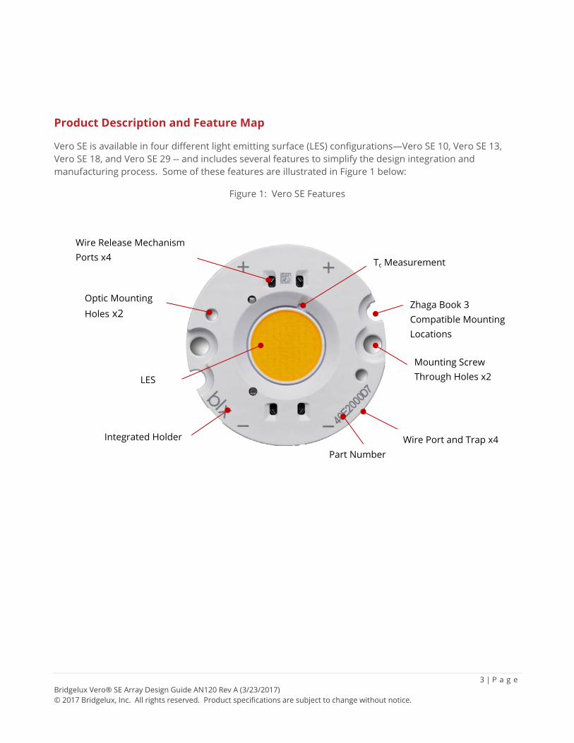
Vero SE is available in four different light emitting surface (LES) configurations—Vero SE 10, Vero SE 13, Vero SE 18, and Vero SE 29 -- and includes several features to simplify the design integration and manufacturing process. Some of these features are illustrated in Figure 1 below:
Figure 1: Vero SE Features
Integrated Holder Wire Port and Trap x4
Optic Mounting Holes x2
Part Number
Mounting Screw Through Holes x2
Wire Release Mechanism Ports x4
Zhaga Book 3 Compatible Mounting Locations
Tc Measurement
LES
4 | P a g e Bridgelux Vero® SE Array Design Guide AN120 Rev A (3/23/2017) © 2017 Bridgelux, Inc. All rights reserved. Product specifications are subject to change without notice.
Handling of Vero SE Arrays
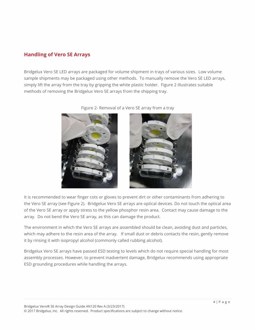
Bridgelux Vero SE LED arrays are packaged for volume shipment in trays of various sizes. Low volume sample shipments may be packaged using other methods. To manually remove the Vero SE LED arrays, simply lift the array from the tray by gripping the white plastic holder. Figure 2 illustrates suitable methods of removing the Bridgelux Vero SE arrays from the shipping tray.
Figure 2- Removal of a Vero SE array from a tray
It is recommended to wear finger cots or gloves to prevent dirt or other contaminants from adhering to the Vero SE array (see Figure 2). Bridgelux Vero SE arrays are optical devices. Do not touch the optical area of the Vero SE array or apply stress to the yellow phosphor resin area. Contact may cause damage to the array. Do not bend the Vero SE array, as this can damage the product.
The environment in which the Vero SE arrays are assembled should be clean, avoiding dust and particles, which may adhere to the resin area of the array. If small dust or debris contacts the resin, gently remove it by rinsing it with isopropyl alcohol (commonly called rubbing alcohol).
Bridgelux Vero SE arrays have passed ESD testing to levels which do not require special handling for most assembly processes. However, to prevent inadvertent damage, Bridgelux recommends using appropriate ESD grounding procedures while handling the arrays.
5 | P a g e Bridgelux Vero® SE Array Design Guide AN120 Rev A (3/23/2017) © 2017 Bridgelux, Inc. All rights reserved. Product specifications are subject to change without notice.
Thermal Management of Vero SE Products
The Vero SE products incorporate the Bridgelux Gen 7 COB technology, which has greatly improved thermal efficiency. The thermal sections below discuss some of the key items needed in measuring and choosing proper thermal solutions for the Vero SE products. For a detailed discussion on thermal management and calculations, refer AN30 Thermal Management for Bridgelux LED Arrays on Bridgelux.com.
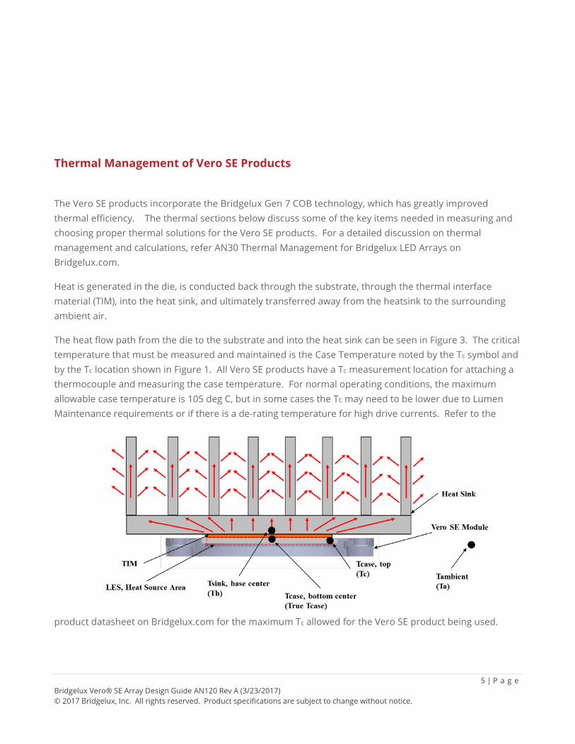
Heat is generated in the die, is conducted back through the substrate, through the thermal interface material (TIM), into the heat sink, and ultimately transferred away from the heatsink to the surrounding ambient air.
The heat flow path from the die to the substrate and into the heat sink can be seen in Figure 3. The critical temperature that must be measured and maintained is the Case Temperature noted by the Tc symbol and by the Tc location shown in Figure 1. All Vero SE products have a Tc measurement location for attaching a thermocouple and measuring the case temperature. For normal operating conditions, the maximum allowable case temperature is 105 deg C, but in some cases the Tc may need to be lower due to Lumen Maintenance requirements or if there is a de-rating temperature for high drive currents. Refer to the
product datasheet on Bridgelux.com for the maximum Tc allowed for the Vero SE product being used.
6 | P a g e Bridgelux Vero® SE Array Design Guide AN120 Rev A (3/23/2017) © 2017 Bridgelux, Inc. All rights reserved. Product specifications are subject to change without notice.
Figure 3: Thermal path from Vero SE substrate through TIM and into heatsink
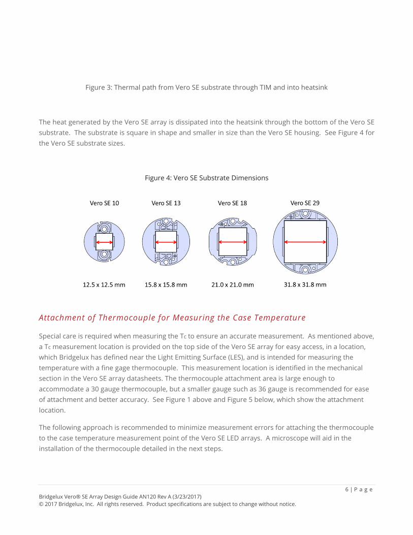
The heat generated by the Vero SE array is dissipated into the heatsink through the bottom of the Vero SE substrate. The substrate is square in shape and smaller in size than the Vero SE housing. See Figure 4 for the Vero SE substrate sizes.
Figure 4: Vero SE Substrate Dimensions
Attachment of Thermocouple for Measuring the Case Temperature
Special care is required when measuring the Tc to ensure an accurate measurement. As mentioned above, a Tc measurement location is provided on the top side of the Vero SE array for easy access, in a location, which Bridgelux has defined near the Light Emitting Surface (LES), and is intended for measuring the temperature with a fine gage thermocouple. This measurement location is identified in the mechanical section in the Vero SE array datasheets. The thermocouple attachment area is large enough to accommodate a 30 gauge thermocouple, but a smaller gauge such as 36 gauge is recommended for ease of attachment and better accuracy. See Figure 1 above and Figure 5 below, which show the attachment location.
The following approach is recommended to minimize measurement errors for attaching the thermocouple to the case temperature measurement point of the Vero SE LED arrays. A microscope will aid in the installation of the thermocouple detailed in the next steps.
7 | P a g e Bridgelux Vero® SE Array Design Guide AN120 Rev A (3/23/2017) © 2017 Bridgelux, Inc. All rights reserved. Product specifications are subject to change without notice.
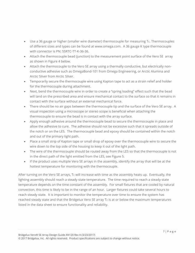
• Use a 36 gauge or higher (smaller wire diameter) thermocouple for measuring Tc. Thermocouples of different sizes and types can be found at www.omega.com. A 36 gauge K type thermocouple with connector is PN: 5SRTC-TT-K-36-36.
• Attach the thermocouple bead (junction) to the measurement point surface of the Vero SE array as shown in Figure 4 below.
• Attach the thermocouple to the Vero SE array using a thermally conductive, but electrically non-conductive adhesive such as OmegaBond-101 from Omega Engineering, or Arctic Alumina and Arctic Silver from Arctic Silver.
• Temporarily secure the thermocouple wire using Kapton tape to act as a strain relief and holder for the thermocouple during attachment.
• Next, bend the thermocouple wire in order to create a “spring loading” effect such that the bead will land on the prescribed area and ensure mechanical contact to the surface so that it remains in contact with the surface without an external mechanical force.
• There should be no air gaps between the thermocouple tip and the surface of the Vero SE array. A visual inspection using a microscope or stereo scope is beneficial when attaching the thermocouple to ensure the bead is in contact with the array surface.
• Apply enough adhesive around the thermocouple bead to secure the thermocouple in place and allow the adhesive to cure. The adhesive should not be excessive such that it spreads outside of the notch or on the LES. The thermocouple bead and epoxy should be contained within the notch and out of the primary light path.
• Place a small strip of Kapton tape or small drop of epoxy over the thermocouple wire to secure the wire down to the top side of the housing to keep it out of the light path.
• The wire of the thermocouple should be routed away from the LES so that the thermocouple is not in the direct path of the light emitted from the LES, see Figure 5.
• If the product uses multiple Vero SE arrays in the assembly, identify the array that will be at the hottest temperature for monitoring with the thermocouple.
After turning on the Vero SE arrays, Tc will increase with time as the assembly heats up. Eventually, the lighting assembly should reach a steady state temperature. The time required to reach a steady state temperature depends on the time constant of the assembly. For small fixtures that are cooled by natural convection, this time is likely to be in the range of an hour. Larger fixtures could take several hours to reach steady state. It is important to monitor the temperature over time to ensure the system has reached steady state and that the Bridgelux Vero SE array Tc is at or below the maximum temperatures listed in the data sheet to ensure functionality and reliability.
8 | P a g e Bridgelux Vero® SE Array Design Guide AN120 Rev A (3/23/2017) © 2017 Bridgelux, Inc. All rights reserved. Product specifications are subject to change without notice.
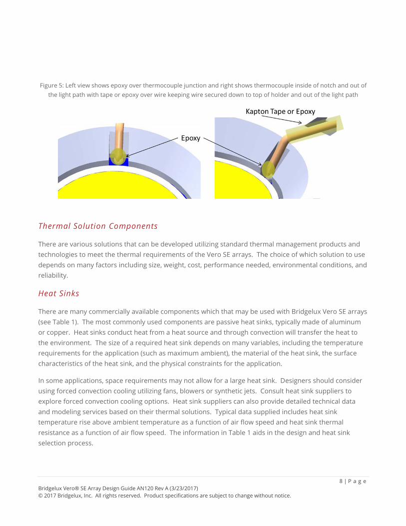
Figure 5: Left view shows epoxy over thermocouple junction and right shows thermocouple inside of notch and out of the light path with tape or epoxy over wire keeping wire secured down to top of holder and out of the light path
Thermal Solution Components
There are various solutions that can be developed utilizing standard thermal management products and technologies to meet the thermal requirements of the Vero SE arrays. The choice of which solution to use depends on many factors including size, weight, cost, performance needed, environmental conditions, and reliability.
Heat Sinks
There are many commercially available components which that may be used with Bridgelux Vero SE arrays (see Table 1). The most commonly used components are passive heat sinks, typically made of aluminum or copper. Heat sinks conduct heat from a heat source and through convection will transfer the heat to the environment. The size of a required heat sink depends on many variables, including the temperature requirements for the application (such as maximum ambient), the material of the heat sink, the surface characteristics of the heat sink, and the physical constraints for the application.
In some applications, space requirements may not allow for a large heat sink. Designers should consider using forced convection cooling utilizing fans, blowers or synthetic jets. Consult heat sink suppliers to explore forced convection cooling options. Heat sink suppliers can also provide detailed technical data and modeling services based on their thermal solutions. Typical data supplied includes heat sink temperature rise above ambient temperature as a function of air flow speed and heat sink thermal resistance as a function of air flow speed. The information in Table 1 aids in the design and heat sink selection process.
9 | P a g e Bridgelux Vero® SE Array Design Guide AN120 Rev A (3/23/2017) © 2017 Bridgelux, Inc. All rights reserved. Product specifications are subject to change without notice.
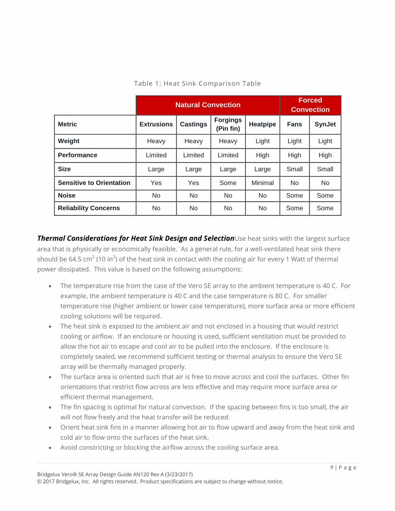
Table 1: Heat Sink Comparison Table
Natural Convection Forced Convection
Metric Extrusions Castings Forgings (Pin fin) Heatpipe Fans SynJet
Weight Heavy Heavy Heavy Light Light Light
Performance Limited Limited Limited High High High
Size Large Large Large Large Small Small
Sensitive to Orientation Yes Yes Some Minimal No No
Noise No No No No Some Some
Reliability Concerns No No No No Some Some
Thermal Considerations for Heat Sink Design and SelectionUse heat sinks with the largest surface area that is physically or economically feasible. As a general rule, for a well-ventilated heat sink there should be 64.5 cm2 (10 in2) of the heat sink in contact with the cooling air for every 1 Watt of thermal power dissipated. This value is based on the following assumptions:
• The temperature rise from the case of the Vero SE array to the ambient temperature is 40 C. For example, the ambient temperature is 40 C and the case temperature is 80 C. For smaller temperature rise (higher ambient or lower case temperature), more surface area or more efficient cooling solutions will be required.
• The heat sink is exposed to the ambient air and not enclosed in a housing that would restrict cooling or airflow. If an enclosure or housing is used, sufficient ventilation must be provided to allow the hot air to escape and cool air to be pulled into the enclosure. If the enclosure is completely sealed, we recommend sufficient testing or thermal analysis to ensure the Vero SE array will be thermally managed properly.
• The surface area is oriented such that air is free to move across and cool the surfaces. Other fin orientations that restrict flow across are less effective and may require more surface area or efficient thermal management.
• The fin spacing is optimal for natural convection. If the spacing between fins is too small, the air will not flow freely and the heat transfer will be reduced.
• Orient heat sink fins in a manner allowing hot air to flow upward and away from the heat sink and cold air to flow onto the surfaces of the heat sink.
• Avoid constricting or blocking the airflow across the cooling surface area.
10 | P a g e Bridgelux Vero® SE Array Design Guide AN120 Rev A (3/23/2017) © 2017 Bridgelux, Inc. All rights reserved. Product specifications are subject to change without notice.
• Natural convection has limitations in how much heat can be removed even if large surface areas are used. If natural convection is determined to be insufficient, then consider using forced convection that can dramatically increase the convection heat transfer coefficient and hence dramatically increase heat transfer. Forced convection cooled heat sinks also allow for thermal solutions with much smaller weight and size.
Thermal Interface Material (TIM) for Vero SE
The TIM material used for the Vero SE should be of sufficient thermal performance to provide coupling between the substrate and the heatsink. Suitable TIMs for all Vero SEs are greases, phase change materials (PCMs), and thermal epoxies. Thermal pads can be used under certain operating conditions for the Vero 10 SE and Vero 13 SE, but generally thermal tapes without the use of TIM is not recommended. See the Table 2 below for guidance.
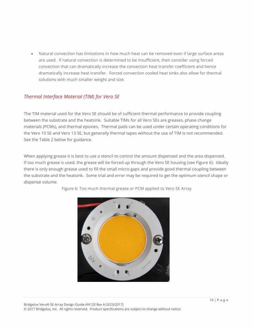
When applying grease it is best to use a stencil to control the amount dispensed and the area dispensed. If too much grease is used, the grease will be forced up through the Vero SE housing (see Figure 6). Ideally there is only enough grease used to fill the small micro-gaps and provide good thermal coupling between the substrate and the heatsink. Some trial and error may be required to get the optimum stencil shape or dispense volume.
Figure 6: Too much thermal grease or PCM applied to Vero SE Array
11 | P a g e Bridgelux Vero® SE Array Design Guide AN120 Rev A (3/23/2017) © 2017 Bridgelux, Inc. All rights reserved. Product specifications are subject to change without notice.
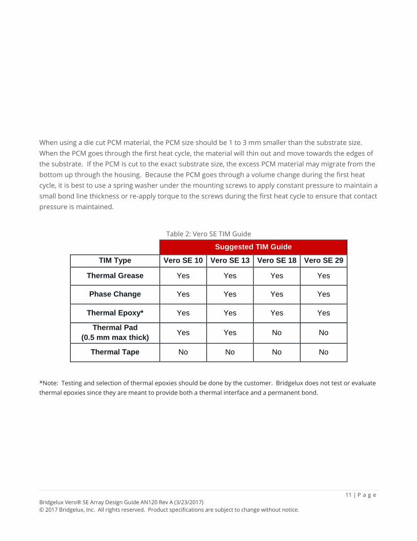
When using a die cut PCM material, the PCM size should be 1 to 3 mm smaller than the substrate size. When the PCM goes through the first heat cycle, the material will thin out and move towards the edges of the substrate. If the PCM is cut to the exact substrate size, the excess PCM material may migrate from the bottom up through the housing. Because the PCM goes through a volume change during the first heat cycle, it is best to use a spring washer under the mounting screws to apply constant pressure to maintain a small bond line thickness or re-apply torque to the screws during the first heat cycle to ensure that contact pressure is maintained.
Table 2: Vero SE TIM Guide Suggested TIM Guide
TIM Type Vero SE 10 Vero SE 13 Vero SE 18 Vero SE 29
Thermal Grease Yes Yes Yes Yes
Phase Change Yes Yes Yes Yes
Thermal Epoxy* Yes Yes Yes Yes
Thermal Pad (0.5 mm max thick) Yes Yes No No
Thermal Tape No No No No
*Note: Testing and selection of thermal epoxies should be done by the customer. Bridgelux does not test or evaluate thermal epoxies since they are meant to provide both a thermal interface and a permanent bond.
12 | P a g e Bridgelux Vero® SE Array Design Guide AN120 Rev A (3/23/2017) © 2017 Bridgelux, Inc. All rights reserved. Product specifications are subject to change without notice.
Mechanical Assembly and Installation
Vero SE is another improvement from previous generation products in user assembly and connection to the lighting system. Vero SE products have two screw holes sized for M3 screws for attachment to the heatsink/light fixture (see Figure 1). A table listing screw size and torque values is shown below in Table 3. The torque values are based on typical machine screws in aluminum heatsinks and not thread forming screws. When tightening the screws, it is best to not fully tighten one side before starting or tightening the other. It is best to tighten each screw in an alternating pattern in quarter or half turn increments until the final torque setting has been achieved.
Screw Torque
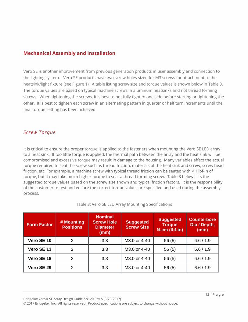
It is critical to ensure the proper torque is applied to the fasteners when mounting the Vero SE LED array to a heat sink. If too little torque is applied, the thermal path between the array and the heat sink will be compromised and excessive torque may result in damage to the housing. Many variables affect the actual torque required to seat the screw such as thread friction, materials of the heat sink and screw, screw head friction, etc. For example, a machine screw with typical thread friction can be seated with < 1 lbf-in of torque, but it may take much higher torque to seat a thread forming screw. Table 3 below lists the suggested torque values based on the screw size shown and typical friction factors. It is the responsibility of the customer to test and ensure the correct torque values are specified and used during the assembly process.
Table 3: Vero SE LED Array Mounting Specifications
Form Factor # Mounting Positions
Nominal Screw Hole Diameter
(mm)
Suggested Screw Size
Suggested Torque
N-cm (lbf-in)
Counterbore Dia / Depth,
(mm)
Vero SE 10 2 3.3 M3.0 or 4-40 56 (5) 6.6 / 1.9
Vero SE 13 2 3.3 M3.0 or 4-40 56 (5) 6.6 / 1.9
Vero SE 18 2 3.3 M3.0 or 4-40 56 (5) 6.6 / 1.9
Vero SE 29 2 3.3 M3.0 or 4-40 56 (5) 6.6 / 1.9
13 | P a g e Bridgelux Vero® SE Array Design Guide AN120 Rev A (3/23/2017) © 2017 Bridgelux, Inc. All rights reserved. Product specifications are subject to change without notice.
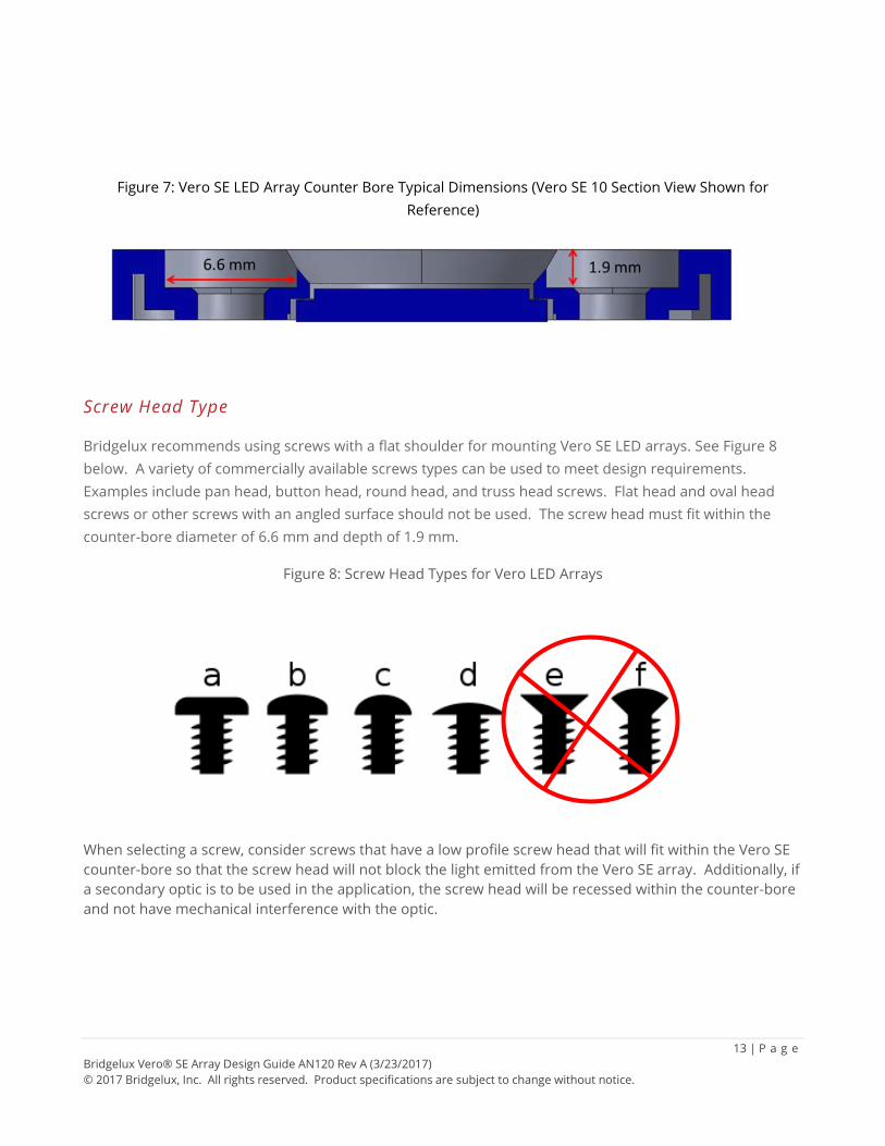
Figure 7: Vero SE LED Array Counter Bore Typical Dimensions (Vero SE 10 Section View Shown for Reference)
Screw Head Type
Bridgelux recommends using screws with a flat shoulder for mounting Vero SE LED arrays. See Figure 8 below. A variety of commercially available screws types can be used to meet design requirements. Examples include pan head, button head, round head, and truss head screws. Flat head and oval head screws or other screws with an angled surface should not be used. The screw head must fit within the counter-bore diameter of 6.6 mm and depth of 1.9 mm.
Figure 8: Screw Head Types for Vero LED Arrays When selecting a screw, consider screws that have a low profile screw head that will fit within the Vero SE counter-bore so that the screw head will not block the light emitted from the Vero SE array. Additionally, if a secondary optic is to be used in the application, the screw head will be recessed within the counter-bore and not have mechanical interference with the optic.
14 | P a g e Bridgelux Vero® SE Array Design Guide AN120 Rev A (3/23/2017) © 2017 Bridgelux, Inc. All rights reserved. Product specifications are subject to change without notice.
Flat Washers, Lock Washers, Self-Locking Fasteners, and Thread Sealants
To prevent loosening of screws during vibration or thermal cycling, Bridgelux recommends using lock washers, self-locking fasteners, or thread-locking sealants as long as the thread-locking sealant is approved for use with LEDs. When using a lock washer, a flat washer should be used between the locking washer and the Vero SE housing to protect the housing from damage. The flat washer will provide a wider distribution of the force applied by the screw and lock washer. The lock washer and flat washer must fit within the counter-bore diameter of 6.6 mm and depth of 1.9 mm.
Wire Installation- Ports
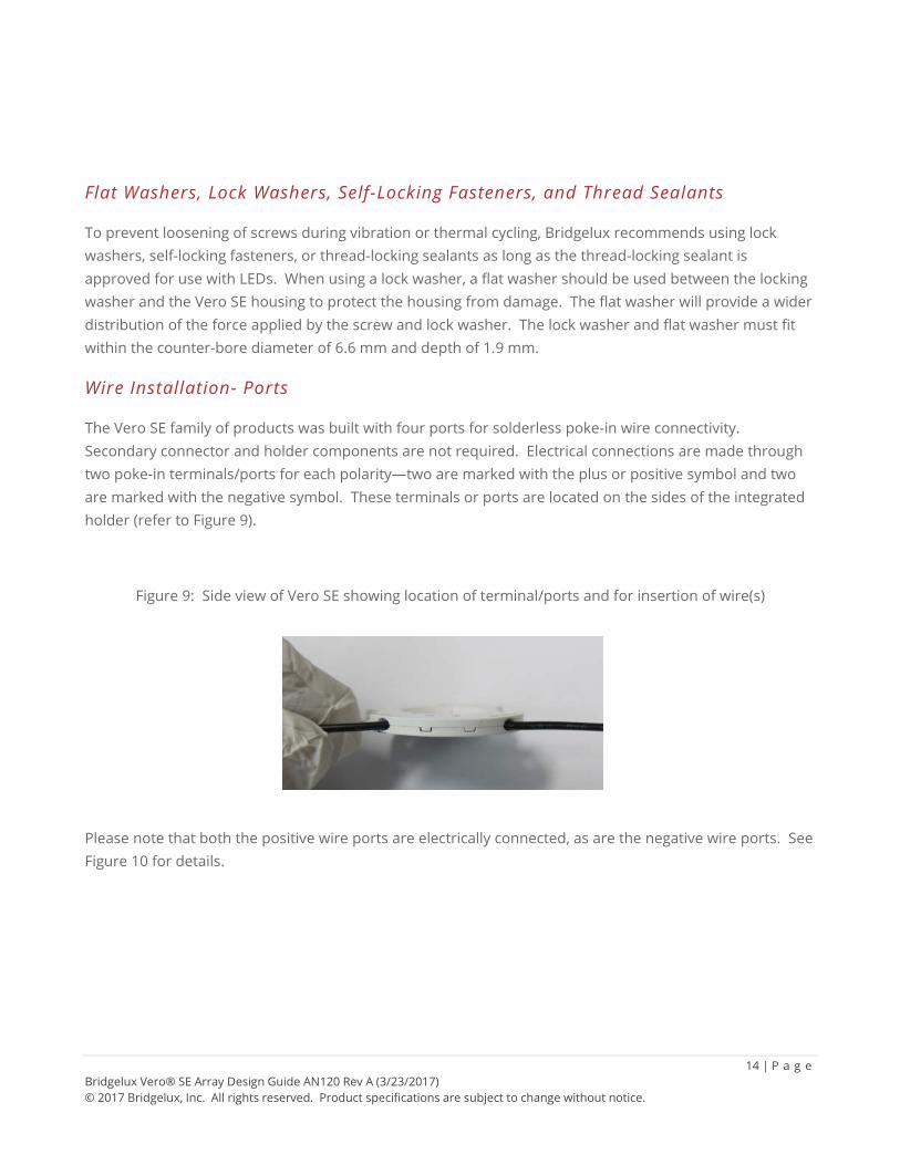
The Vero SE family of products was built with four ports for solderless poke-in wire connectivity. Secondary connector and holder components are not required. Electrical connections are made through two poke-in terminals/ports for each polarity—two are marked with the plus or positive symbol and two are marked with the negative symbol. These terminals or ports are located on the sides of the integrated holder (refer to Figure 9).
Figure 9: Side view of Vero SE showing location of terminal/ports and for insertion of wire(s)
Please note that both the positive wire ports are electrically connected, as are the negative wire ports. See Figure 10 for details.
15 | P a g e Bridgelux Vero® SE Array Design Guide AN120 Rev A (3/23/2017) © 2017 Bridgelux, Inc. All rights reserved. Product specifications are subject to change without notice.
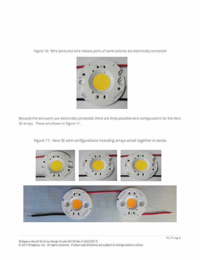
Figure 10: Wire ports and wire release ports of same polarity are electrically connected
Because the wire ports are electrically connected, there are three possible wire configurations for the Vero SE arrays. These are shown in Figure 11.
Figure 11: Vero SE wire configurations including arrays wired together in series
Please note that when energized, all four wire ports are live.
16 | P a g e Bridgelux Vero® SE Array Design Guide AN120 Rev A (3/23/2017) © 2017 Bridgelux, Inc. All rights reserved. Product specifications are subject to change without notice.
Wire Installation- Wire Requirements
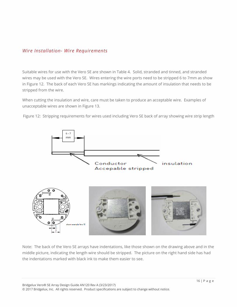
Suitable wires for use with the Vero SE are shown in Table 4. Solid, stranded and tinned, and stranded wires may be used with the Vero SE. Wires entering the wire ports need to be stripped 6 to 7mm as show in Figure 12. The back of each Vero SE has markings indicating the amount of insulation that needs to be stripped from the wire.
When cutting the insulation and wire, care must be taken to produce an acceptable wire. Examples of unacceptable wires are shown in Figure 13.
Figure 12: Stripping requirements for wires used including Vero SE back of array showing wire strip length
Note: The back of the Vero SE arrays have indentations, like those shown on the drawing above and in the middle picture, indicating the length wire should be stripped. The picture on the right hand side has had the indentations marked with black ink to make them easier to see.
6 – 7 mm
17 | P a g e Bridgelux Vero® SE Array Design Guide AN120 Rev A (3/23/2017) © 2017 Bridgelux, Inc. All rights reserved. Product specifications are subject to change without notice.
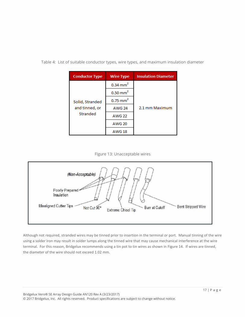
Table 4: List of suitable conductor types, wire types, and maximum insulation diameter
Figure 13: Unacceptable wires
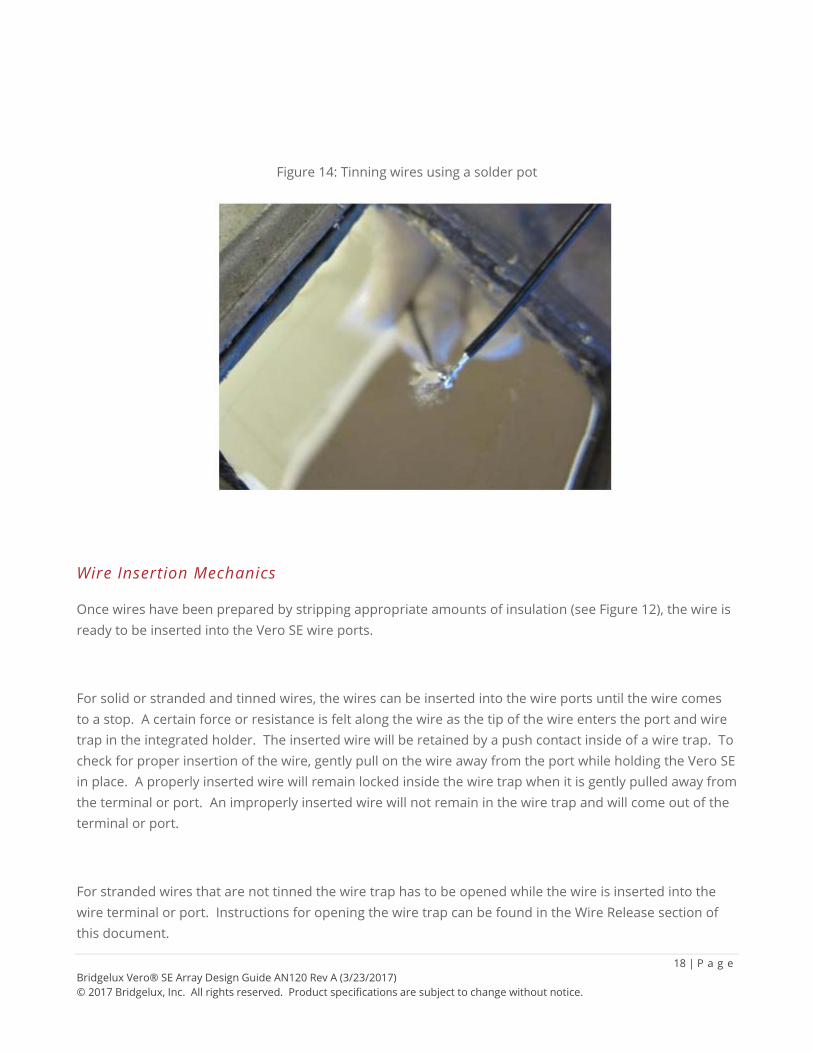
Although not required, stranded wires may be tinned prior to insertion in the terminal or port. Manual tinning of the wire using a solder iron may result in solder lumps along the tinned wire that may cause mechanical interference at the wire terminal. For this reason, Bridgelux recommends using a tin pot to tin wires as shown in Figure 14. If wires are tinned, the diameter of the wire should not exceed 1.02 mm.
18 | P a g e Bridgelux Vero® SE Array Design Guide AN120 Rev A (3/23/2017) © 2017 Bridgelux, Inc. All rights reserved. Product specifications are subject to change without notice.
Figure 14: Tinning wires using a solder pot
Wire Insertion Mechanics
Once wires have been prepared by stripping appropriate amounts of insulation (see Figure 12), the wire is ready to be inserted into the Vero SE wire ports.
For solid or stranded and tinned wires, the wires can be inserted into the wire ports until the wire comes to a stop. A certain force or resistance is felt along the wire as the tip of the wire enters the port and wire trap in the integrated holder. The inserted wire will be retained by a push contact inside of a wire trap. To check for proper insertion of the wire, gently pull on the wire away from the port while holding the Vero SE in place. A properly inserted wire will remain locked inside the wire trap when it is gently pulled away from the terminal or port. An improperly inserted wire will not remain in the wire trap and will come out of the terminal or port.
For stranded wires that are not tinned the wire trap has to be opened while the wire is inserted into the wire terminal or port. Instructions for opening the wire trap can be found in the Wire Release section of this document.
19 | P a g e Bridgelux Vero® SE Array Design Guide AN120 Rev A (3/23/2017) © 2017 Bridgelux, Inc. All rights reserved. Product specifications are subject to change without notice.
Wire Release
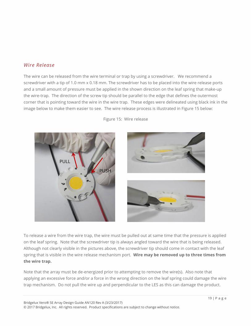
The wire can be released from the wire terminal or trap by using a screwdriver. We recommend a screwdriver with a tip of 1.0 mm x 0.18 mm. The screwdriver has to be placed into the wire release ports and a small amount of pressure must be applied in the shown direction on the leaf spring that make-up the wire-trap. The direction of the screw tip should be parallel to the edge that defines the outermost corner that is pointing toward the wire in the wire trap. These edges were delineated using black ink in the image below to make them easier to see. The wire release process is illustrated in Figure 15 below:
Figure 15: Wire release
To release a wire from the wire trap, the wire must be pulled out at same time that the pressure is applied on the leaf spring. Note that the screwdriver tip is always angled toward the wire that is being released. Although not clearly visible in the pictures above, the screwdriver tip should come in contact with the leaf spring that is visible in the wire release mechanism port. Wire may be removed up to three times from the wire trap.
Note that the array must be de-energized prior to attempting to remove the wire(s). Also note that applying an excessive force and/or a force in the wrong direction on the leaf spring could damage the wire trap mechanism. Do not pull the wire up and perpendicular to the LES as this can damage the product.
PUSH
PULL
20 | P a g e Bridgelux Vero® SE Array Design Guide AN120 Rev A (3/23/2017) © 2017 Bridgelux, Inc. All rights reserved. Product specifications are subject to change without notice.
Electrical Management The selection of a suitable electronic driver is critical to achieve optimal performance from Vero SE arrays.
General Driver Recommendations
LED drivers convert available input power into the required output current and voltage, and are analogous to ballasts used with fluorescent and other conventional light sources. When selecting a driver for use with a Vero SE array, follow these basic guidelines:
• Drive the Vero SE array using constant current sources, not constant voltage sources. • Do not apply a reverse voltage to the Vero SE array. • If multiple arrays are used, the arrays are preferred to be connected in series (not in parallel). For
more detailed information on multiple array circuit design recommendations please refer to Bridgelux Application Note AN92 on Electrical Drive Considerations for Bridgelux Gen7 LED Arrays.
• UL max voltage rating requirements might limit total number of arrays that may be placed in series. Consult with UL and Bridgelux sales representatives for details.
• When selecting a driver, please ensure that the current does not exceed the Absolute Maximum Rating noted in the product data sheet.
Driver Selection
A driver should be selected to enable operation over the entire voltage range of the selected Vero SE array. The typical voltage for each array is included in the performance tables in the Vero SE data sheet. Note that the voltage range of the driver should be selected to allow sufficient guard band for the typical voltages shown in the Vero SE data sheet. Additional guard band will be required if the array is operated at a case temperature other than the temperature values listed in the datasheet.
It is the responsibility of the designer to ensure that the selected LED driver meets all local regulatory requirements. We also recommend consideration of the following specifications when selecting or designing an LED driver.
• Power factors greater than 0.9 are recommended. • Design or select drivers that are highly efficient over the range of loads expected in the lighting
system. • The expected life of the LED driver should match that of the lighting system. • Ensure compliance to all regulatory and approbation requirements. • Some applications may benefit, or require, LED drivers that include active feedback. • Ripple is the small and unwanted residual periodic variation of the direct current output of an AC
to DC LED driver. Ripple values that are less than ± 10% are recommended. • Specify an LED driver with low noise to avoid interference and/or violation of regulated standards.
21 | P a g e Bridgelux Vero® SE Array Design Guide AN120 Rev A (3/23/2017) © 2017 Bridgelux, Inc. All rights reserved. Product specifications are subject to change without notice.
• Carefully consider the type of dimming technology that is used to ensure application needs are met
For more detailed information on drivers, electrical connection options, and best practices for driving the arrays refer to AN92.
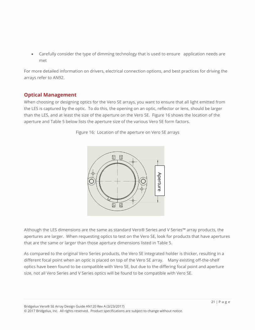
Optical Management When choosing or designing optics for the Vero SE arrays, you want to ensure that all light emitted from the LES is captured by the optic. To do this, the opening on an optic, reflector or lens, should be larger than the LES, and at least the size of the aperture on the Vero SE. Figure 16 shows the location of the aperture and Table 5 below lists the aperture size of the various Vero SE form factors.
Figure 16: Location of the aperture on Vero SE arrays
Although the LES dimensions are the same as standard Vero® Series and V Series™ array products, the apertures are larger. When requesting optics to test on the Vero SE, look for products that have apertures that are the same or larger than those aperture dimensions listed in Table 5.
As compared to the original Vero Series products, the Vero SE integrated holder is thicker, resulting in a different focal point when an optic is placed on top of the Vero SE array. Many existing off-the-shelf optics have been found to be compatible with Vero SE, but due to the differing focal point and aperture size, not all Vero Series and V Series optics will be found to be compatible with Vero SE.
Aperture
22 | P a g e Bridgelux Vero® SE Array Design Guide AN120 Rev A (3/23/2017) © 2017 Bridgelux, Inc. All rights reserved. Product specifications are subject to change without notice.
Table 5: Aperture dimensions by Vero SE form factor
Form Factor LES (mm) Aperture (mm) Vero SE 10 9.6 14.0 Vero SE 13 13.4 19.3 Vero SE 18 18.4 24.5 Vero SE 29 29.2 35.4
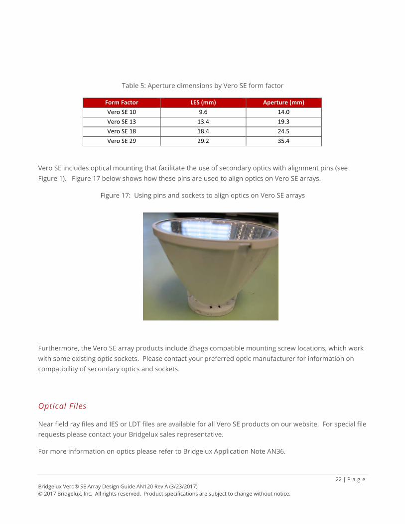
Vero SE includes optical mounting that facilitate the use of secondary optics with alignment pins (see Figure 1). Figure 17 below shows how these pins are used to align optics on Vero SE arrays.
Figure 17: Using pins and sockets to align optics on Vero SE arrays
Furthermore, the Vero SE array products include Zhaga compatible mounting screw locations, which work with some existing optic sockets. Please contact your preferred optic manufacturer for information on compatibility of secondary optics and sockets.
Optical Files
Near field ray files and IES or LDT files are available for all Vero SE products on our website. For special file requests please contact your Bridgelux sales representative.
For more information on optics please refer to Bridgelux Application Note AN36.
23 | P a g e Bridgelux Vero® SE Array Design Guide AN120 Rev A (3/23/2017) © 2017 Bridgelux, Inc. All rights reserved. Product specifications are subject to change without notice.
Chemical Compatibility Optimizing performance and reliability of a lighting system using Bridgelux Vero SE arrays requires safe handling and use of appropriate manufacturing procedures and materials during the assembly of the array into the lighting system. Careful consideration must be given to the materials and chemicals used when processing the Vero SE and to materials that are incorporated into a luminaire. This section provides a list of commonly used chemicals that should be avoided or carefully managed during processing of Vero SE and during their subsequent use.
Silicone encapsulation is commonly used by most High Brightness LED manufacturers, including Bridgelux. The silicone encapsulation is permeable to gas molecules. The gas molecules, including volatile organic compounds (VOC’s), halogen and sulfur compounds, can interact with silicone and other components that comprise the Bridgelux Vero SE and cause degradation in performance. The possibility and extent of degradation is dependent on the type of chemical, the concentration of the chemical, the temperature during exposure, and the length of time the LED array is exposed to the chemical. Additional considerations should be given to IP rated or “sealed” luminaires that create “air tight environments” around the array. Luminaires sealed in this fashion can trap potentially damaging gas molecules from manufacturing processes or subsequent out-gassing of materials used in the luminaire which can result in long term exposure of the arrays to the contaminant.
The source of the gas molecules can be out-gassing from polymeric materials such as glues, gaskets, paints and/or under-cured materials. Materials used inside a luminaire with a potential to outgas should be characterized as part of the luminaire design to understand the environment that will be surrounding the Bridgelux Vero SE during the luminaire lifetime. The silicone encapsulation is also vulnerable to non-polar fluids and solvents commonly used during the manufacturing process of the luminaire such as cleaning, oil assisted drilling, and any processes that would allow the array to come into contact with the fluids or solvents. Care should be taken such that the arrays are protected from such chemicals to avoid ingress of small non-polar molecules into the encapsulation silicone.
Common chemicals that are known to be harmful to Bridgelux Vero SE are listed in Table 6 below. Note that the chemicals listed in Table 6 may be found in various states – liquid, gas, and/or solid. All physical states of these chemicals can be harmful to the arrays, but those that are in a gaseous state, such as volatile organic compounds (VOCs), can readily permeate the lens material of the array and damage the array internally and/or externally.
Because it is impossible to determine all of the chemicals that may be detrimental to the performance of the Bridgelux Vero SE, the list of chemicals above may not be exhaustive. It is the responsibility of the luminaire manufacturer to ensure that any and all materials used in the luminaire design or manufacturing process does not cause damage to the subsystems.
24 | P a g e Bridgelux Vero® SE Array Design Guide AN120 Rev A (3/23/2017) © 2017 Bridgelux, Inc. All rights reserved. Product specifications are subject to change without notice.
For additional information on chemicals that are potentially hazardous to LEDs please refer to the following industry resource:
Lighting Industry Association Technical Statement 13 http://www.thelia.org.uk
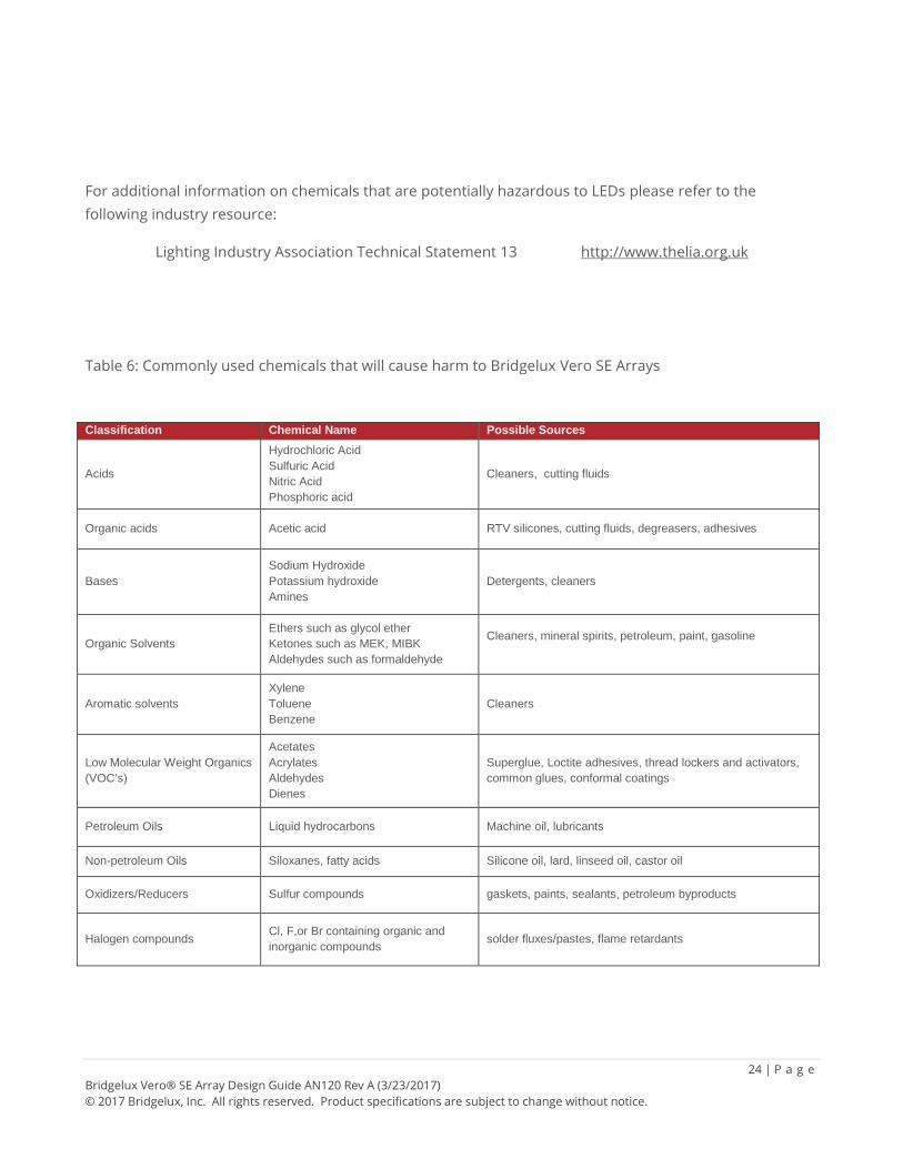
Table 6: Commonly used chemicals that will cause harm to Bridgelux Vero SE Arrays
Classification Chemical Name Possible Sources
Acids
Hydrochloric Acid Sulfuric Acid Nitric Acid Phosphoric acid
Cleaners, cutting fluids
Organic acids Acetic acid RTV silicones, cutting fluids, degreasers, adhesives
Bases Sodium Hydroxide Potassium hydroxide Amines
Detergents, cleaners
Organic Solvents Ethers such as glycol ether Ketones such as MEK, MIBK Aldehydes such as formaldehyde
Cleaners, mineral spirits, petroleum, paint, gasoline
Aromatic solvents Xylene Toluene Benzene
Cleaners
Low Molecular Weight Organics (VOC’s)
Acetates Acrylates Aldehydes Dienes
Superglue, Loctite adhesives, thread lockers and activators, common glues, conformal coatings
Petroleum Oils Liquid hydrocarbons Machine oil, lubricants
Non-petroleum Oils Siloxanes, fatty acids Silicone oil, lard, linseed oil, castor oil
Oxidizers/Reducers Sulfur compounds gaskets, paints, sealants, petroleum byproducts
Halogen compounds Cl, F,or Br containing organic and inorganic compounds solder fluxes/pastes, flame retardants
25 | P a g e Bridgelux Vero® SE Array Design Guide AN120 Rev A (3/23/2017) © 2017 Bridgelux, Inc. All rights reserved. Product specifications are subject to change without notice.
Disclaimers
This applications note has been prepared to provide guidance on the application of Bridgelux LEDs in customer applications. Bridgelux provides this information in good faith, but does not assume any responsibility or liability for design deficiencies that might exist in a customer design.
BRIDGELUX MAKES NO REPRESENTATION OR WARRANTY WITH RESPECT TO THE ACCURACY, APPLICABILITY, FITNESS, OR COMPLETENESS OF THE CONTENTS OF THIS APPLICATIONS NOTE. BRIDGELUX DISCLAIMS ANY WARRANTIES (EXPRESS OR IMPLIED), MERCHANTABILITY, OR FITNESS FOR ANY PARTICULAR PURPOSE. BRIDGELUX SHALL IN NO EVENT BE HELD LIABLE TO ANY PARTY FOR ANY DIRECT, INDIRECT, PUNITIVE, SPECIAL, INCIDENTAL OR OTHER CONSEQUENTIAL DAMAGES ARISING DIRECTLY OR INDIRECTLY FROM ANY USE OF THIS TECHNICAL REPORT, WHICH IS PROVIDED “AS IS.”.
It is the responsibility of the customer to ensure that the design meets all necessary requirements and safety certifications for its intended use.
26 | P a g e Bridgelux Vero® SE Array Design Guide AN120 Rev A (3/23/2017) © 2017 Bridgelux, Inc. All rights reserved. Product specifications are subject to change without notice.
About Bridgelux At Bridgelux, we help companies, industries and people experience the power and possibility of light. Since 2002, we’ve designed LED solutions that are high performing, energy efficient, cost effective and easy to integrate. Our focus is on light’s impact on human behavior, delivering products that create better environments, experiences and returns—both experiential and financial. And our patented technology drives new platforms for commercial and industrial luminaires.
For more information about the company, please visit bridgelux.com twitter.com/Bridgelux facebook.com/Bridgelux youtube.com/user/Bridgelux linkedin.com/company/bridgelux-inc-_2 WeChat ID: BridgeluxInChina
46430 Fremont Boulevard Fremont, CA 94538 Tel (925) 583-8400 www.bridgelux.com