Embed Size (px)
Citation preview

Wendell H. BoothZIN Technologies, Incorporated, Middleburg Heights, Ohio
Boiling Experiment Facility (BXF):Post Flight AssessmentAnomaly Investigation Report
NASA/CR—2012-216036
December 2012
60081–RPT–0402
https://ntrs.nasa.gov/search.jsp?R=20130001808 2018-08-09T14:24:25+00:00Z

Wendell H. BoothZIN Technologies, Incorporated, Middleburg Heights, Ohio
Boiling Experiment Facility (BXF):Post Flight AssessmentAnomaly Investigation Report
NASA/CR—2012-216036
December 2012
60081–RPT–0402

Level of Review

NASA/CR—2012-216036 iii
Contents1.0 Introduction ........................................................................................................................................... 1
1.1 Background ................................................................................................................................. 11.2 Purpose ........................................................................................................................................ 21.3 Scope ........................................................................................................................................... 2
2.0 Documents ............................................................................................................................................ 23.0 Investigation Results ............................................................................................................................. 2
3.1 Exterior Visual Inspection and Packing at KSC ......................................................................... 33.2 Unpacking and Exterior Visual Inspection at ZIN ...................................................................... 33.3 Voltage Bus Resistance Check ................................................................................................... 33.4 Functional Check ........................................................................................................................ 43.5 Dissolved Gas Concentration Measurement ............................................................................... 43.6 High Speed Camera Alignment Check ....................................................................................... 43.7 24 Vdc Bus 1 Anomaly Check .................................................................................................... 43.8 Containment Vessel Gas Sampling ............................................................................................. 53.9 Containment Vessel Disassembly: Inspect Interior and Install CV Legs ................................... 53.10 24 Vdc Bus 1 Component Resistance Check .............................................................................. 53.11 Pre-Drain Fluid Sampling and Analysis ..................................................................................... 63.12 Flight Hardware Drain/Fluid Disposal ........................................................................................ 63.13 Pressure and Temperature Measurement Accuracy Check ......................................................... 73.14 Containment Vessel Disassembly: Uninstall CV Top Plate/CV Fan Visual Inspection
and Touch Test ............................................................................................................................ 73.15 Room Temperature Leak Test ..................................................................................................... 83.16 Elevated Temperature Leak Test ................................................................................................ 83.17 BXF Embedded Controller Inspection and Bench Test .............................................................. 8
4.0 Conditional/Optional Investigation ....................................................................................................... 94.1 2.7 mm MABE Embedded Controller Inspection ....................................................................... 94.2 7.0 mm MABE Embedded Controller Inspection ....................................................................... 94.3 Avionics Box Output Voltage Test ........................................................................................... 104.4 Avionics Box Interior Visual Inspection .................................................................................. 104.5 Bulk Fluid Heater Extraction and Inspection ............................................................................ 10
4.5.1 Extraction and Visual Inspection (Section 3.1 of PLAN–0394) ..................................... 104.5.2 Post-Extraction Resistance Check (Section 3.2 of PLAN–0394) ................................... 114.5.3 X-Ray Inspection (Section 3.3 of PLAN–0394) ............................................................. 114.5.4 Heater Wiring Dissection (Section 3.4 of PLAN–0394)................................................. 11
4.6 FOD Analysis ............................................................................................................................ 125.0 Conclusions ......................................................................................................................................... 12
5.1 High Speed Camera Misalignment ........................................................................................... 125.2 Dissolved Gas Concentration .................................................................................................... 125.3 On-Orbit Anomaly .................................................................................................................... 12
Appendix A.—Acronyms and Abbreviations ............................................................................................. 15Appendix B.—Functional Check Details .................................................................................................... 17Appendix C.—HSC Alignment Check Images ........................................................................................... 35Appendix D.—Extraction and Visual Inspection Photos ............................................................................ 37Appendix E.—X-Ray Inspection Photos .................................................................................................... 79Appendix F.—Approvals .......................................................................................................................... 141Appendix G.—Revisions .......................................................................................................................... 143Reference .................................................................................................................................................. 144


NASA/CR—2012-216036 1
Boiling Experiment Facility (BXF): Post Flight AssessmentAnomaly Investigation Report
Wendell H. BoothZIN Technologies, Inc.
Middleburg Heights, Ohio 44130
1.0 IntroductionThe Boiling eXperiment Facility (BXF) is an experiment package designed for the Microgravity
Science Glovebox (MSG) located on the International Space Station (ISS). Two experiments operate inthis facility, the Microheater Array Boiling Experiment (MABE) and the Nucleate Pool BoilingExperiment (NPBX). The working fluid used by the facility is perfluoro-n-hexane.
MABE utilizes two arrays of microheaters along with measurement circuitry to record the local heattransfer characteristics on the surface of the heaters during boiling in a microgravity environment. Eachheater is individually controlled to operate at a constant temperature.NPBX consists of an array of five microcavities, or nucleation sites, on the surface of a polishedaluminum wafer. The heat applied to each nucleation site is individually controlled, and the data obtainedwill be used to further the understanding of the heat transfer associated with nucleate boiling heat flux.
1.1 Background
BXF was turned over to NASA and packaged for launch aboard space shuttle flight ULF-5 in October2010. After a lengthy delay, ULF-5 launched on February 24, 2011. BXF was installed into MSG andbegan Flight operations on March 22, 2011 (GMT 2011/081). BXF operated successfully for the next3 weeks with the exception of five problems. The High Speed Camera image of the 7 mm MABE Arraywas out of alignment such that one row and one column of the array could not be seen in the image.During Week 2, the dissolved gas concentration was measured at 299 ppm, which exceeded therequirement of < 100 ppm. The Space Acceleration Measurement System (SAMS) unit that was toprovide acceleration data for BXF was inoperable. Data from another unit was used instead. Theconnector from MSG video recorder 4 to the downlinking system was disconnected for a short period,and there were problems with the MSG laptop computer (MLC) that prevented file transfer from BXFduring the calibration activities.
On April 11, 2011 (GMT 2011/101), the dissolved gas concentration was measured at 712 ppm, andon that day a major anomaly occurred. The voltage on 24 Vdc Bus 1 dropped unexpectedly to about 6 V,and an off-nominal current was drawn from MSG. This condition went unnoticed for approximately8 min at which point a fluid loop pressure warning occurred. The BXF system entered into safe mode andtripped the safety circuit to remove power from the heaters and motors. It was observed that all pressurereadings and some temperature readings were off-nominal. Attempts were made to recover by resettingthe embedded controllers (ECs), restarting the BXF software, and cycling power to BXF. All attemptsfailed. The system was shutdown.
Over the next couple of weeks, multiple meetings and an Engineering Review Board (ERB) wereheld to study the data collected, propose possible root causes, determine methods for troubleshooting on-orbit, and put together a plan and procedure for carrying out troubleshooting on-orbit. Reference theAnomaly Troubleshooting ERB Presentation slides in Appendix E of the Mission Summary Report,60081-RPT-0404. On April 27, 2011 (GMT 2011/117), the on-orbit troubleshooting was performed. Theresults of the troubleshooting indicated a possible electrical short on 24 Vdc Bus 1. It was also determinedthat with the 24 Vdc Bus 1 circuit breaker open, some NPBX science could still be obtained. One moreweek of operations with modified procedures was performed to obtain some limited NPBX science.

NASA/CR—2012-216036 2
BXF was returned on space shuttle flight ULF-7, and Post-Flight troubleshooting activities wereperformed in accordance with the BXF Post-Flight Assessment Anomaly Investigation Plan, 60081-PLAN-0383.
1.2 Purpose
This document serves as the report for presenting the results and conclusions of investigationactivities that were performed to determine the root causes of the anomaly, camera misalignment, anddissolved gas concentration issues and to verify the calibration and accuracy of the pressure andtemperature measurements.
1.3 Scope
This report covers the results of Post-Flight Assessment (PFA) investigation activities that wereperformed on the BXF Flight hardware per 60081-PLAN-0383.
2.0 DocumentsThe following documents are applicable to this report.
Document Number Document Title60081–PLAN–0383 Post-Flight Assessment Anomaly Investigation Plan60081–PROC–0390 Post-Flight Assessment Hardware Visual Inspection at KSC60081–PROC–0368 Packing and Shipping Procedure60081–PROC–0384 Voltage Bus Resistance Check for Anomaly Investigation60081–PROC–0378 Flight Operations Anomaly Troubleshooting Procedure60081–PROC–0379 NPBX Background Heaters Only Flight Operations ProcedureMGUEMSGBXFN001 BXF Setup Crew Procedure60081–PROC–0391 Containment Vessel Gas Sampling Procedure60081–PROC–0304 Containment Vessel Assembly Procedure, 60081M01A20560081–PROC–0385 24Vdc Bus 1 Component Resistance Check for Anomaly Investigation60081–PROC–0392 Pre-Drain Fluid Sampling and Analysis Procedure60081–PROC–0397 Fluid Vapor Pressure Determination, FOD Collection, and Fluid Transfer Procedure60081–RPT–0399 Post-Flight Pressure Measurement Verification Report60081–RPT–0400 Post-Flight Temperature Measurement Verification Report60081–PROC–0300 Fluids System Leak Test Procedure60081–PROC–0393 Fluids System Leak Test at Elevated Temperature60081–RPT–0401 Post-Flight Assessment BXF EC Engineering Checkout Report60081–PROC–0075 Avionics Box Test Procedure60081–PLAN–0394 Post-Flight Assessment Cartridge Heater Inspection Plan60081–PROC–0395 Cartridge Heater Post-Extraction Resistance Check60081–PROC–0396 Cartridge Heater Wiring Dissection60081–PROC–0389 Post-Flight FOD Collection Procedure
3.0 Investigation ResultsThe following subsections give brief summaries of the results for each investigation activity that was
conducted on the BXF Flight hardware. Only brief summaries are given. Detailed results are documentedin individual reports, as-run procedures, attachments to the as-run plans, or appendices of this report as

NASA/CR—2012-216036 3
specified in each subsection. Only results of activities are presented. For detailed information on eachactivity itself, reference 60081–PLAN–0383.
3.1 Exterior Visual Inspection and Packing at KSC
At the beginning of the visual inspection at Kennedy Space Center (KSC), it was observed that theBXF Flight hardware components were positioned and oriented in a disorganized manner. TheContainment Vessel (CV) was located on a cart, and the remaining components were located on a table inthe center of the lab. A few Non-BXF Flight components were mixed in with those of BXF.
In general, there were no findings that could be readily associated with the anomaly during the KSCvisual inspection. All components were in their packings. Some packings were open, and some had minortears and punctures. Some components were observed to have minor marks and scratches. Notableobservations were as follows.
Minor damage found on connector P108 of cable W301Dirt and minor damage found on the HSC MirrorMissing protective CCD cap of HSC S/N 001Fingerprints and damaged thermal pad on AB Mounting PlateHSC Processor S/N 001 appeared to be unused—ramification being that HSC Processor S/N 002was the one used on orbit.
Details for the visual inspection and packing of the hardware are documented in the as-run procedures60081–PROC–0390 and 60081–PROC–0368, respectively. Both are located in manufacturing work order(MWO) 60081M01L123–01.
3.2 Unpacking and Exterior Visual Inspection at ZIN
Additional observations were made by the technicians during unpacking of the hardware after arrivalat ZIN.
Pin E of connector P302 was found to be slightly bentConnector P8 of Cable W205 was not cappedMinor damage found on CV Mounting PlateDebris found on outside of 2.5 mm MABE LensRTV was missing from a screw located on top of the Avionics Box near connector J1
None of the additional observations made could be readily associated with the on-orbit anomaly.Details are documented in the as-run procedure 60081–PROC–0368 located in MWO
60081M01L123–01.
3.3 Voltage Bus Resistance Check
The Voltage Bus Resistance Check found a short between the 24Vdc Bus 1 voltage line and the J101connector shell (CV structure). The resistance measured was 5.43 A bonding measurement betweenconnector J101 and the CV structure also failed. The bond resistance was 43 These results showedthat there was a problem located somewhere within the CV.
Details are documented in the as-run procedure 60081–PROC–0384 located in MWO60081M01L123–01.

NASA/CR—2012-216036 4
3.4 Functional Check
The Functional Check successfully demonstrated that the BXF Flight hardware functional capabilitywas the same as it was just prior to being disassembled and stowed on orbit.
Some details are documented in the as-run procedure 60081–PROC–0378 located in MWO60081M01L123–01. Remaining details are in electronic form located in Appendix B of this report.
3.5 Dissolved Gas Concentration Measurement
The Dissolved Gas Concentration, measured August 18, 2011, after return to ZIN, was found to be603 ppm at a fluid temperature of 21.5°C and a fluid pressure of 0.36 atm. For comparison, the followingtable shows a list of Dissolved Gas Concentration values over time during Flight operations.
Date Gas concentration,ppm
Fluid temperature,°C
Fluid pressure,atm
March 21, 2011 (GMT Day 081) –46 30.3 0.35
March 31, 2011 (GMT Day 091) 299 33.1 0.46
April 3, 2011 (GMT Day 094) 261 23.1 0.31
April 10, 2011 (GMT Day 101) 712 24.8 0.42
April 26, 2011 (GMT Day 117) 737 23.6 0.41
May 8, 2011 (GMT Day 129) 589 23.1 0.37
May 11, 2011 (GMT Day 132) 543 30.1 0.46
Based on the measurements made Post-Flight and throughout operations, the gas contaminationleakage appears to have stopped when on-orbit testing ended in May 2011.
The PFA Dissolved Gas Concentration Measurement is documented in the as-run procedure 60081–PROC–0379 located in MWO 60081M01L123–01.
3.6 High Speed Camera Alignment Check
Assembly of the BXF Flight hardware per MGUEMSGBXFN001 did not result in an HSC Cameramisalignment on the ground as severe as that observed on orbit. Troubleshooting found that amisalignment more similar to that observed on orbit could be induced by unloading the HSC MountingBracket and not fully seating the MABE lens against the HSC Alignment Bracket set screws.
These observations suggest that minor compliance in the camera mounting hardware, incompleteseating of the lens on the set screws, or a combination of both of these factors could have caused theimage misalignment observed on-orbit. The one attempt that was made to correct the alignment duringFlight operations was unsuccessful. It is possible, with further opportunities to iterate, that properalignment could have been achieved during Flight operations. The potential for success, however, wouldhave been hindered by the following factors: crew time constraints; the inability to have the systempowered during alignment for image viewing; and the lack of a high fidelity Engineering Model to utilizefor guidance and assistance. These factors would have likely made future attempts similarly unsuccessful.Details are documented in an attachment to the as-run BXF PFA plan, 60081–PLAN–0383, located inMWO 60081M01L123–01. The HSC images acquired during the alignment check can be found inAppendix C of this report.
3.7 24 Vdc Bus 1 Anomaly Check
In accordance with the BXF PFA plan, the 24 Vdc Bus 1 Anomaly Check was not performed,because the BXF Flight hardware failed the Voltage Bus Resistance Check of section 3.3 of the plan.

NASA/CR—2012-216036 5
3.8 Containment Vessel Gas SamplingThis activity was not originally part of the BXF PFA plan but was added due to growing concern that
a Bulk Fluid Heater may have overheated and generated perfluoroisobutene (PFIB) from the BXF Fluid.PFIB is a hazardous gas and has an acceptable exposure limit of only 10 parts per billion. The intent ofthe CV Gas Sampling was to determine whether any fluid, and possibly PFIB, might be present in the CVinterior space.
Two samples of gas were taken from the interior space of the CV, and both samples were analyzedfor hydrogen fluoride (HF), fluorine (F2), and perfluoro-n-hexane (PFnH). No HF or F2 were detected.This greatly increased the confidence that no PFIB was present in the CV interior space. Some PFnH wasdetected at very low levels, 334 and 437 ppm. This low level of PFnH was attributed to low diffusionleakage through the BXF Test Chamber soft seals. If there had been a major leak of PFnH into the CVinterior space, the concentration would have been several orders of magnitude greater. It was, therefore,concluded that the BXF Test Chamber was intact (first level of containment still in place) and that it wasokay to proceed with disassembly of the CV.In addition to the results discussed above, the analysis also showed the presence of carbon byproducts inthe gas samples, suggesting that a combustion event may have taken place within the CV interior space.
Details are documented in the as-run procedure 60081–PROC–0391 located in MWO60081M01A205–03.
3.9 Containment Vessel Disassembly: Inspect Interior and Install CV LegsThis activity was modified slightly to include monitoring of the short found on 24 Vdc Bus 1. The
intent was to determine the nature of the short, whether it was intermittent or stable, and isolate itslocation.
Disassembly of the CV revealed the presence of burnt/melted wiring. The wiring leading to CartridgeHeater Assembly S/N 010, utilized for Bulk Fluid Heater 1, exhibited a dark black and browndiscoloration in and around connector J215. Some of the discoloration was observed on nearby wires. Theoverall internal insulation sleeving of the cartridge heater wiring appeared to have melted and protrudedthrough the shield braid near connector J215. A red tie wrap that held the cartridge heater wiring in placewas damaged, melted, and fused to the shield braid.
There is clearly a problem associated with Bulk Fluid Heater 1.Details of disassembly are documented in the as-run procedure 60081–PROC–0304 located in MWO
60081M01A205–03. Observations are noted in an attachment to the as-run BXF PFA plan, 60081–PLAN–0383, located in MWO 60081M01L123–01.
3.10 24 Vdc Bus 1 Component Resistance CheckCartridge Heater Assembly S/N 010 (Bulk Fluid Heater 1) failed the 24Vdc Bus 1 Component
Resistance Check. Heater 1 had multiple shorts as follows.
Cartridge Heater S/N 010(Bulk Fluid Heater 1)
Location Resistance, Pass criteria
Between power and return 2.4Between power and structure 6.26Between return and structure 5.97

NASA/CR—2012-216036 6
Additional failures were found on Cartridge Heater Assembly S/N 012 (Bulk Fluid Heater 2) asfollows.
Cartridge Heater S/N 012(Bulk Fluid Heater 2)
Location Resistance, Pass criteria
Between power and structure 35.6Between return and structure 34.1
Cartridge Heater Assembly S/N 009 (Bulk Fluid Heater 3) passed the resistance check along with allother components on 24 Vdc Bus 1.
These results confirmed a problem with Bulk Fluid Heater 1 and revealed a possible hiddendegradation of Bulk Fluid Heater 2.
Details are documented in the as-run procedure 60081–PROC–0385 located in MWO60081M01A205–03.
3.11 Pre-Drain Fluid Sampling and Analysis
This activity was not originally part of the BXF PFA plan but was added due to stronger evidence thatone or more Bulk Fluid Heaters overheated, increasing concerns that PFIB was produced.As a consequence of determining that Bulk Fluid Heaters 1 and 2 were shorted, two samples of the BXFfluid were taken. One sample was sent out for analysis to determine whether PFIB was present or not. Thesecond sample was stored for possible analysis in-house. The analysis results confirmed the presence ofPFIB in the BXF Fluid at 90 parts per million. The acceptable exposure level (AEL) of PFIB is 10 partsper billion.
Upon notification of this result, the BXF CV was reassembled back into the CV Housing toreestablish three levels of containment. All BXF PFA activities were placed on hold until it wasdetermined how to proceed.
Details are documented in the as-run procedure 60081–PROC–0392 located in MWO60081M01A205–03.
3.12 Flight Hardware Drain/Fluid Disposal
This activity was not originally part of the BXF PFA plan but was added due to the discovery of thepresence of hazardous PFIB in the BXF Fluid.
After weighing the pros and cons of several courses of action, it was finally determined that the BXFFluid would be removed from the BXF hardware and disposed of by the NASA Hazardous WasteManagement organization. The fluid was transferred into two disposal cylinders, and NASA HazardousWaste Management arranged for a disposal vendor to pick them up.
Just prior to the transfer process, a series of temperature and pressure measurements were taken todetermine the Dissolved Gas Concentration of the fluid, and during the transfer, the fluid was passedthrough a filter to collect any foreign object debris (FOD) present in the fluid. The filter containing thecollected FOD was stored for future analysis.
The resulting Dissolved Gas Concentration value was 870 ppm at 20.7 °C and 0.40 atm. Thetemperature and pressure measurements, however, were taken in a manner that differed greatly from themethod used for prior Dissolved Gas Concentration calculations. At the time these measurements weretaken, a GSE pressure transducer was used instead of the transducers of the BXF system, an externalfluids system was attached to the BXF hardware, and there was no bellows control of BXF Fluid pressure.While it is possible that there was an increase in gas contamination at this time, due to the differences inhow the measurements were taken, the value of 870 ppm is likely not very meaningful.

NASA/CR—2012-216036 7
Details are documented in the as-run procedure 60081–PROC–0397 located in MWO60081M01A205–03.
3.13 Pressure and Temperature Measurement Accuracy Check
A comparison between the Pre and Post-Flight results of pressure measurement testing found thatthere was little to no deviation in data that could not be explained by the combined uncertainty of theBXF system and the pressure calibrator used for testing. This suggested that the state of the BXFelectrical system, post-anomaly, had no effect on the output of the pressure transducers.Post-Flight temperature measurement verifications were performed on the BXF Bulk Fluid, Cavity,Surround, Background and Insulation (Rake) Thermistors with the BXF avionics in the post-anomalyflight-like configuration. Unlike the pressure measurement verification, a complete end-to-end calibrationof the temperature measurement system could not be performed since the locations and configurations ofthe thermistor elements made it impossible to do so without complete disassembly and possible damageto the system and components of interest. Instead, the thermistors were disconnected from the rest of thesystem as close to the element as possible and replaced with a variable load. The load on eachtemperature circuit was varied to simulate each element’s output based on the Pre-Flight thermistorcalibration results and the temperature ranges of interest. Ambient temperature checks of the thermistorelements were also performed to support the system verification results. All thermistor elements, exceptthe known non-conformance of Cavity Thermistor 5, showed good agreement with Pre-Flight calibrationresults indicating that the elements themselves and associated cabling were in good working order.
In general, all of the random variation observed in the temperature measurement verification datashowed reasonable agreement with the Pre-Flight uncertainty analyses conducted. There were a numberof instances where data outliers were observed in the Post-Flight results, and these may be attributed toexperimental errors as identified and discussed in 60081–RPT–0400. Since the outliers generally occurredonly at the extremes of the temperature ranges tested (suggesting saturation of the measurement channel)and the rest of the data followed expected trends, there appears to be no significant impact to the BXFtemperature measurements in the post-anomaly configuration of the system.
Details for the pressure and temperature measurement accuracy checks are documented in 60081–RPT–0399 and 60081–RPT–0400, respectively.
3.14 Containment Vessel Disassembly: Uninstall CV Top Plate/CV Fan Visual Inspectionand Touch Test
This activity was modified to include a CV Fan Inspection and Touch Test to determine whether“smoke” may have been generated that could have adversely affected the pressure sensors.
The Top Plate was uninstalled from the CV to prepare for subsequent PFA activities. After the TopPlate was uninstalled, the fans located on it underwent a visual inspection and “white glove” touch test.Reddish-brown FOD was found present on the leading edge of the fan blades and the inner surface of thehousing on both CV Fans. The material had a slight reddish appearance when adhered to the fans, buttook on more of a brownish appearance when transferred to the white cloth used for the touch test.The substantial amount of FOD present on the CV Fans suggests that “smoke” may have been generatedwithin the CV interior space during the anomaly on-orbit.
Details for the disassembly are documented in the as-run procedure 60081–PROC–0304 located inMWO 60081M01A205–03. Details for the CV Fan visual inspection and touch test are documented in anattachment to the BXF PFA plan, 60081–PLAN–0383, located in MWO 60081M01L123–01.

NASA/CR—2012-216036 8
3.15 Room Temperature Leak Test
An overall instantaneous vacuum leak rate of 0.9×10⁻⁸ sccs helium (He) was measured, and apermeation leak rate of 4.1×10⁻⁶ sccs He was measured over 2.7 hr. For pressure, a leak rate of 1.1×10⁻⁷
sccs He was measured over 1.5 hr, which was also the background rate.During Pre-Flight leak testing, the results were as follows:
Vacuum Instantaneous Leak Rate: 7.0×10⁻⁷ sccs HeVacuum Permeation Leak Rate: 5.4×10⁻⁶ sccs He, over 4.8 hrPermeation Leak Rate: 1.3×10⁻⁷ sccs He, over 15 min (background rate)
As can be seen above, the Post-Flight leak rates are comparable to the Pre-Flight leak rates, whichsuggests that there have been no new leaks since that time.
It should be noted that during individual component sniffing while under pressure, two CartridgeHeater Assemblies, S/Ns 012 and 009 (Bulk Fluid Heaters 2 and 3, respectively) were found to have aslightly higher localized leak rate of 1.7×10⁻⁷ sccs He. No leaks were found on any other components,including the Cartridge Heater Assembly S/N 010 (Bulk Fluid Heater 1).
Details are documented in the as-run procedure 60081–PROC–0300 located in MWO60081M01A206–02.
3.16 Elevated Temperature Leak Test
This activity was not originally part of the BXF PFA plan but was added to determine the credibilityof the presence of temperature-dependent leaks that may have been induced by the elevated temperaturesexperienced by the BXF hardware on-orbit.
The Elevated Temperature Leak Test, which used the CV Housing and a thermal chamber set at50 °C, produced an overall instantaneous vacuum leak rate of 1.0×10⁻⁷ sccs He and a permeation leak rateof 1.7×10⁻⁵ sccs He over 2.8 hr. The test was repeated at room temperature, again using the CV Housing,to produce an instantaneous leak rate of 1.1×10⁻⁸ sccs He and a permeation leak rate of 7.5×10⁻⁶ sccs Heover 4.3 hr. The room temperature results were comparable to those generated during the “bagged” RoomTemperature Leak Test (Section 3.15) and are an order of magnitude lower than the leak rates observed atan elevated temperature of 50 °C.
Individual component spraying at elevated temperature inside the thermal chamber without the CVHousing did not reveal any specific leak sources. In general, all components and seals appeared to sharein the increased leak rate at higher temperatures.
Details are documented in the as-run procedure 60081–PROC–0393 located in MWO60081M01A206–02.
3.17 BXF Embedded Controller Inspection and Bench Test
Visual inspection of the BXF Embedded Controller (EC) found the same FOD that was found duringthe CV Fan Visual Inspection. The reddish-brown FOD was located in areas of the board that wereexposed to the air flow of the fans.
The BXF EC passed bench testing with the exception of two failures. The Flow Meter Input failed,because the worst case error of +15 counts exceeded the success criterion of ± 10 counts. The controlrelays for Bulk Fluid Heaters 2 and 3 failed, because their on-state resistancessuccess criterion of <
It should be noted that the control relay for Bulk Fluid Heater 1 passed the success criterion.The Flow Meter Input was not specified as a requirement for BXF. The success criterion was,
therefore, arbitrarily selected based on actual results achieved during development. The current worst case

NASA/CR—2012-216036 9
error of +15 counts is equivalent to a fluid flow measurement error of +0.006 L/min. This failure is likelynot related to the on-orbit anomaly.
The higher on-state resistance of each failing control relay reduced the amount of power delivered toBulk Fluid Heaters 2 and 3 resulting in less than nominal heating of the BXF Fluid with Bulk FluidHeater 1 carrying more of the burden. Consequently, the time required to achieve desired fluidtemperatures may have been longer than normal.
Details of the visual inspection are documented in the as-run process plan PP60081E01A520–3located in MWO 60081M01A205–03. Details of the bench test are documented in 60081–RPT–0401.
4.0 Conditional/Optional InvestigationThe following subsections give brief summaries of the results for each conditional/optional
investigation activity that was conducted on the BXF Flight hardware. The activities in this section wereeither conditional or optional, being performed only when certain conditions were met, or at the discretionof ZIN and NASA project management. Only brief summaries are given. Detailed results are documentedin individual reports, as-run procedures, attachments to the as-run plans, or appendices of this report asspecified in each subsection. Only the results of activities are presented. For detailed information on eachactivity itself, reference 60081–PLAN–0383.
4.1 2.7 mm MABE Embedded Controller Inspection
The original BXF PFA plan specified this activity be an inspection and bench test, but the projectdetermined that a bench test was not necessary since the investigation results were pointing towards theBulk Fluid Heaters as the source of the failure. This activity was reduced in scope to a visual inspectiononly.
The visual inspection of the 2.7 mm MABE EC found the same FOD that was found during the CVFan Visual Inspection. The reddish-brown FOD was located in areas of the board that were exposed to theair flow of the fans. All other observations were nominal.
It is unlikely that the 2.7 mm MABE EC contributed to the on-orbit anomaly.This visual inspection is documented in the as-run process plan PP60081E01A501–3 located in
MWO 60081M01A205–03.
4.2 7.0 mm MABE Embedded Controller Inspection
The original BXF PFA plan specified this activity be an inspection and bench test, but the projectdetermined that a bench test was not necessary since the investigation results were pointing towards theBulk Fluid Heaters as the source of the failure. This activity was reduced in scope to a visual inspectiononly with extra attention paid to the circuit components for microheater 27.
The visual inspection of the 7.0 mm MABE EC found the same FOD that was found during the CVFan Visual Inspection. The reddish-brown FOD was located in areas of the board that were exposed to theair flow of the fans. Additionally, attention was focused on the board components associated with controlof microheater 27, because it was noted during operations that this microheater had stopped functioning.All components involved with microheater 27 appeared nominal. All other observations also appearednominal.
It is unlikely that the 7.0 mm MABE EC contributed to the on-orbit anomaly.This visual inspection is documented in the as-run process plan PP60081E01A519–3 located in
MWO 60081M01A205–03.

NASA/CR—2012-216036 10
4.3 Avionics Box Output Voltage Test
The original BXF PFA plan specified this activity be a full-fledged bench test, but the projectdetermined that a full-fledged bench test was not necessary since the investigation results were pointingtowards the Bulk Fluid Heaters as the source of the failure. This activity was reduced in scope to anoutput voltage test only.
All output voltages of the BXF Avionics Box (AB) passed the success criterion of ±10% of nominal.The resulting voltages are listed below.
Voltage Bus Voltage,V
12 Vdc Bus 11.95224 Vdc Bus 1 23.97124 Vdc Bus 2 23.943
It is unlikely that the BXF AB contributed to the on-orbit anomaly.Details are documented in the as-run procedure 60081–PROC–0075 located in MWO
60081M01A438–04.
4.4 Avionics Box Interior Visual Inspection
Visual Inspection of the interior space of the BXF AB found everything to be nominal.This inspection is documented in the as-run process plan PP60081M01A438–3 located in MWO
60081M01A438–04.
4.5 Bulk Fluid Heater Extraction and Inspection
The extraction and inspection investigation activities for the Bulk Fluid Heaters were conducted inaccordance with the Post-Flight Assessment Cartridge Heater Inspection Plan, 60081–PLAN–0394. Thefollowing subsections discuss the results of each activity.
4.5.1 Extraction and Visual Inspection (Section 3.1 of PLAN–0394)All three Cartridge Heaters Assemblies were removed from the BXF Test Chamber and visually
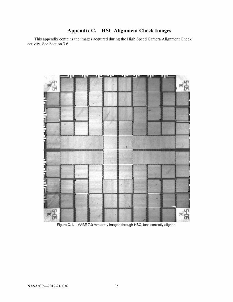
inspected. The metal sheaths of Cartridge Heaters S/Ns 012 and 009 (Bulk Fluid Heaters 2 and 3,respectively) appeared discolored and blackened. Heater 2 appeared more blackened than Heater 3. Otherthan the discoloration, however, no additional damage was observed.
Cartridge Heater S/N 010 (Bulk Fluid Heater 1) could not be extracted from its port fitting on the TestChamber. So, the entire fitting was removed from the chamber and left in place on the heater. Heater 1showed extreme damage at two locations along the sheath. Melting of the Incoloy 800 is evident in bothlocations. The brownish magnesium oxide (MgO) insulating material and greenish remains of the nickelchromium (NiCr) wiring inside are also visible. Melting points of the various materials are listed below.
Material Melting Point,°C
Incoloy 800 1385Magnesium oxide 2800Nickel chromium 1400
The damage observed on Bulk Fluid Heater 1 proves that temperatures in excess of 1400 °C wereachieved on-orbit.

NASA/CR—2012-216036 11
Details are documented in an attachment to the as-run PFA Cartridge Heater Inspection Plan, 60081–PLAN–0394, located in MWO 60081M01A206–02. Photos taken during the inspection can be found inAppendix D of this report.
4.5.2 Post-Extraction Resistance Check (Section 3.2 of PLAN–0394)The Post-Extraction Resistance Check yielded similar results for Bulk Fluid Heaters 2 and 3 as those
obtained during the 24 Vdc Bus 1 Component Resistance Check. Heater 2 had partial shorts to the heatersheath, but not the wiring shield. Heater 3 passed the check.
The results of Bulk Fluid Heater 1 were erratic. A few of the results technically passed, but theresistance value was not stable. It was still evident in the recorded data that Heater 1 suffered a majorfailure.
Details are documented in the as-run procedure 60081–PROC–0395 located in MWO60081M01A206–02.
4.5.3 X-Ray Inspection (Section 3.3 of PLAN–0394)X-rays of the Flight Cartridge Heater Assemblies showed the obvious damage of S/N 010 (Bulk Fluid
Heater 1). The two damaged areas are easily seen. When S/Ns 012 and 009 (Bulk Fluid Heaters 2 and 3,respectively) are compared, there appears to be a subtle difference between them. The internal heater coilof S/N 012 appears to be slightly unwound and irregular, but these observations are subjective.
Details are documented in an attachment to the as-run PFA Cartridge Heater Inspection Plan, 60081–PLAN–0394, located in MWO 60081M01A206–02. Photos of the Cartridge Heater x-ray images can befound in Appendix E of this report.
4.5.4 Heater Wiring Dissection (Section 3.4 of PLAN–0394)Two heaters were dissected. Cartridge Heater S/N 012 (Bulk Fluid Heater 2) was dissected first
followed by Cartridge Heater S/N 010 (Bulk Fluid Heater 1).Throughout all stages of dissection for Heater 2, observations were nominal, and the heater resistance
The Post-Dissection Resistance Check of Heater 2 found two partial shorts, each, between the heater sheath and both the power and return lines going into the sheath. This is in
agreement with prior investigation results.Difficulties were encountered during the dissection of Heater 1. The wiring shield braid could not be
pulled back from the connector, because the shield was fused with the internal insulation sleeving.Cutting open the shield braid proved to be a slow process, as it was found that the shield had beenhardened. After the shield was cut open, it was observed that the internal insulation sleeving wascarbonized near the connector. The sleeving crumbled apart easily as the dissection proceeded. Theinsulation of the internal wiring appeared blackened overall, but whitened over the crimped area. Thewire insulation near the connector was melted away leaving bare exposed wire. When the insulationsleeving was finally removed from around the connector, it was observed that the connector was meltedand completely encasing the internal contacts. The contacts could not be extracted. During the dissection,the wiring separated from the heater sheath on its own without the need for cutting it, and the heatersheath became bent at one of the damaged portions of the sheath. The heater resistance was unstable andvaried greatly as the assembly was handled.Post-Dissection Resistance Check. nd bothpower and return lines. The wiring that separated from the heater sheath failed continuity testing.
Details are documented in two copies, one for each heater, of the as-run procedure 60081–PROC–0396 located in MWO 60081M01A206–02.

NASA/CR—2012-216036 12
4.6 FOD Analysis
The original BXF PFA plan included FOD collection along with the analysis, however, this wasbefore the discovery of PFIB in the BXF Fluid. When the Fluid was disposed of, the opportunity wastaken at that time to collect any FOD present. This activity was reduced in scope to an analysis only.
Also, originally this activity was for Fluid FOD only. When the CV Fan FOD was discovered, thisactivity was expanded to include collection and analysis of the CV Fan FOD.The filter containing FOD collected during the Flight Hardware Drain/Fluid Disposal activity wasanalyzed by NASA GRC using a Field Emission Scanning Electron Microscope (FESEM). The analysisfound the presence of fluorine, magnesium, aluminum, silicon, chromium, and in some cases, iron andnickel. Magnesium was consistently found in many of the particles analyzed. The following table lists themost likely sources of the elements detected in the Fluid FOD.
Element(s) Source(s)Magnesium MgO Insulation of Bulk Fluid Heater 1OxygenNickel Incoloy 800 and NiCr Resistance Wiring of Bulk Fluid Heater 1,
Stainless Steel (SS) Tubing of BXF Fluids SystemChromiumIronAluminum BXF Test ChamberFluorine Soft Goods and Insulating Materials throughout BXF SystemSilicon
A sample of the CV Fan FOD was collected and also sent for analysis by NASA GRC using aFESEM. The analysis consistently found the presence of carbon, fluorine, silicon, and oxygen. Tin,sodium, calcium, aluminum, and sulfur were also detected. Some of these elements, especially fluorine,carbon, and oxygen, are likely the result of decomposition of materials making up the burned/meltedwiring of Bulk Fluid Heater 1. Some of these materials are Halar (tie wrap), Viton (insulation sleeving),Teflon (wire insulation), and nylon (connector).
Collection of the CV Fan FOD is documented in the as-run procedure 60081–PROC–0389 located inMWO 60081M01A205–03. The Fluid and CV Fan FOD analyses are documented in reports generated byNASA GRC, and these reports are available in files maintained by the NASA Project Manager.
5.0 Conclusions5.1 High Speed Camera Misalignment
Based on the results outlined in Section 3.6, it can be concluded that the high speed camera (HSC)misalignment was due to compliance in the HSC hardware. It is possible that correct alignment couldhave been achieved with more time and iteration.
5.2 Dissolved Gas Concentration
The results of Sections 3.5, 3.15, and 3.16 suggest that the overall leak rate of the BXF hardwareincreased when the hardware was exposed to higher operating temperatures on-orbit. This was notanticipated, and the hardware was leak tested only at room temperatures before Flight.
5.3 On-Orbit Anomaly
It can be concluded from the investigation results that Cartridge Heater S/N 010 (Bulk Fluid Heater 1)overheated. The heater temperature had to have reached at least 1400 °C in order to melt the Incoloy 800and NiCr materials of the heater. The heat that was generated probably transferred via thermal conductiondown the cartridge heater wiring causing the burn and melt damage observed near the connector. The

NASA/CR—2012-216036 13
burning and melting of the heater and its wiring led to the creation of an electrical short on 24 Vdc Bus 1.This short would have caused the 24 Vdc Bus 1 DC/DC converter to go into current limiting mode,reducing voltage output, while at the same time, causing higher than nominal current draw from MSG.
The investigation results also suggest that Cartridge Heater S/Ns 012 and 009 (Bulk Fluid Heaters 2and 3, respectively) may have also overheated, or came close to doing so.The manufacturers of the cartridge heaters and BXF Fluid (PFnH) were consulted to determine thepossible reasons why the heaters overheated. The following is a list of the most likely causes:
Lack of direct heater temperature monitoring and control allowed overheating to occur.The dissipation heat flux of the cartridge heaters was within the range required for the onset ofboiling (4 W/cm2 versus 6 to 10 W/cm2) in normal gravity (Ref. 1).Fluid flow rate may have been too low to carry heat away from the heaters.Microgravity may have inhibited convective removal of heat from the heaters.
One or more of the factors above contributed to a scenario in which nucleation boiling of the fluidmay have been induced around the heaters. In the case of Heater 1, this nucleation boiling may haveprogressed to film boiling, causing the heater to become completely enveloped in vapor. The vapor, inturn, would have acted as a thermal insulator and significantly reduced heat transfer from the heater to thefluid. This would have caused the heater to enter into a “runaway” condition in which the heatertemperature increases extremely rapidly. The Bulk Fluid temperature sensors throughout the TestChamber would not have detected this local temperature rise at the heater.


NASA/CR—2012-216036 15
Appendix A.—Acronyms and AbbreviationsAB Avionics BoxAEL Acceptable Exposure Limitatm atmospheresBXF Boiling eXperiment FacilityCCD Charged Coupled DeviceCV Containment Vesseldc or DC direct currentEC Embedded ControllerERB Engineering Review BoardF2 fluorineFESEM Field Emission Scanning Electron MicroscopeFOD Foreign Object DebrisGMT Greenwich Mean TimeGRC NASA Glenn Research CenterGSE Ground Support EquipmentHe heliumHF hydrogen fluorideHSC high speed cameraISS International Space StationKSC NASA Kennedy Space CenterL/min liters per minuteMABE Microheater Array Boiling ExperimentMgO magnesium oxideMSG Microgravity Science GloveboxMWO Manufacturing Work OrderNASA National Aeronautics and Space AdministrationNiCr nickel chromiumNPBX Nucleate Pool Boiling eXperimentPFA Post-Flight AssessmentPFIB perfluoroisobutenePFnH perfluoro-n-hexaneppm parts per millionRTV Room Temperature VolatileS/N serial numbersccs standard cubic centimeters per secondULF Utilization and Logistics FlightZIN ZIN Technologies


NASA/CR—2012-216036 17
Appendix B.—Functional Check DetailsThis appendix contains the BXF Ops Display screenshots, acquired HSC images, Command Log file,
and Housekeeping Data files generated during the Functional Check. See Section 3.4.
Figure B.1.—Screen displays for RS-422 Communication test: Fluid System Tab for BXFOPSDisplay (top left) and forSidekick (top right), NPBX Experiment Tab for BXFOPSDisplay (bottom left) and for Sidekick (bottom right).
if 11!li~ ~~lLL [[[
III •.
ill
Ii flH d ji II .!l! ! J id'
!! II
I n I I
'.oj,
I I i
I, I [~~~~[~
L ~I!.
ij' III i ~ I
'j'II!Jill!1 IL
I' "I!
I I'
I I'
I I
I , J
nl 1
111 ,
1.1
-
ji I
I 1.2!
1 ; 1 ~f II 1
I! • ..
-
I 'rnE Ji ill
! I ,"!
f I Jl
tl
! lu ~ Iili[~}l
! ~
•• ~ . In 111
1 ~ ~lnt~ ~lUJlijih I
It! lid III 'H Ii ,H
,. I Ill, I I . I
! !Jf!
Uill
,Iolli 'ilr
I m
ill
! 1""--,-,-,,,-,,
~~ L~£~ I"ll~ll i jl n II
r!ll~ ~~lLL [li[ IIJlh
III
lll!n ! Ii Ii !!!
!l il"l' I
II ill" I" I • , ,j
,
1:1 [~l~n~
L
• ~I!. j j , I iI i ~
I ~'
'I I!! I " jl
I L
il' L
illI
l.'
11
,1
1
'1
'1 '1 '1 '1 I M
!]-;] LL ~ll!l 'L L
! iL!L i ilil 1lil!1 ililil I
I ! I I
'1'1'1'1'1 '1'1'1 11Jll!l~ j Ii j
Ii
_ LLL LL, LLL ,lfii'PI !l •• d~~ !
. .
. '!
.Ii~ ~'''" l
1 IIi Ii I!
"r,;;" •• "
It
·
; h
!!,l j!
!l
1 ~ '1'1'1'1 'l'l'l'l ""
'"
1 1 L LLLL ILLLL (~
.1
! ,I,
llii I
i ,I d I! . 11111 !nHi,n~!I~iH"i
11jlllllllill I
.' " 1
1m
",
"I
"'"
!.!
:;;!' 1 m
il! !
-I~
.. ,,"
~hlll m
ill
t..(.
I Ii
v"
c Y'I':....
i1 ~H!!:!!:I!I
-~!'
I'!' II,j"
l I m
m
llj!jil lpjil
1 """, , I
I ~~LI'
-,
, '1
~l!
, ll~li lJlIllliJill, -
I II~-I"
lllll""
Illoill
,-••
Hg
iP
j.

NASA/CR—2012-216036 18
Figure B.2.—Screen displays for RS-422 Communication test: MABE Experiment TAB for BXFOPSDisplay (top left)and for Sidekick (top right), System Tab for BXFOPSDisplay (bottom left) and for Sidekick (bottom right).
1_a- I_ I ... _ ... I .. c-l(--' ... · Quouo Ia-1 _ ... _. - ...... -'''', .. ..- , ~ I
-r---~ ~--........ =-- • - __ r---~
~~~~ ~- ~ ......... '_ ..... r-~ ......... __ .r-~ -,-..... r---~ ---- -",_--..-.................... ................... ................ ............... ..................
.... ""' ....... ' ... r---~ ,-----"..i
"--""'- r---~ _ ..... w .. , .. r-~
~-- ..... r-~ ,-----"..i ..-~--... r---~ ..... _,_ .... ,r----~
.... --- r-~ _,,,,C«tr<j
.-===~~. - I 1
_'lOt_c-. ...---~ __ -c-. . - ~_c-. 1I _ .... 0<-~ . .. _LIDo_
--""'- ==:- - - r 11 - . ,_ .... . .,..
-, ... ~ ...... -~ _KC_r... "',- j,., ..... ~II""" - I ~ I
..... _ 1 ___ 1_"-- 1_0-. _ I
--~ ~- ....---_t<_r-.... "'c_ I'.,""'" ~ ....... - I ~ I
-"'''!mil''''"," -... , ,,
"''' !mI''''''''" -... '" "" I/mI""" " -... "'"I/mI"""''' <-... ... "'''!mI''',"",,' ''- ... ""ImtI"".". <-... " .
... _-, .. ='!~.,. -,----~
-
-"'''.,. .. ''' ....
-=1 . ..... -. 0., _ _
•.. --0_-
_"J .. !20'u ... ,,· ... ~ ..... -
~-........ T_ .... '~
t ... ~ .. -· fi,., _ .... c-__ ~
..... --~ . ...... -~ -... ,--.~ ...,..-~
-=J ---- r - r - I ........
-_''''~ ~- p;;;--
.... ' ... "_ .... ,~ T ... ~ ........ ·fi,.,_
- ... ~- Fii·"'-..... -........ ~ ''''''''''''''' fi'''' --,-..... ~ "",..-~
---- r - r -1-
...... - -- I .... _ .. __ .. _-_ ....... ____ 00) 00._ .... ,_ ....... _ <M>ll_ ..... '-O) ~ --· ....... - ·fi"" -
- fi""~~
- -,-------,-------<M>ll_ ..... ~ -....... ,--~ __ .t_ .. ~.~
_ ...... -...... - -- I .... _,--_ .. _-_ ...... ____ 00) 00._."'.,_ ....... _
<M>"_ ..... '-O) ....!!!..l -.--... -.~ -~ ~.~
--,-------,------_. C..O:"'_ ..... ~ -....... ,-..... ~
.............. ,--~

NASA/CR—2012-216036 19
Figure B.3.—Screen displays for Systems Initialization Test: Fluid System Tab for BXFOPSDisplay (top left) and forSidekick (top right), MABE Experiment Tab for BXFOPSDisplay (bottom left) and for Sidekick (bottom right).
<Hi
!.
i
~lit~ ~~~lL ~~~ II j!il ! jl 1/
!!! ! J illl! I!
Ij Ii ii I
"j
<
Iff
111 lliU.~~~[ L
1 U
ljljlli~
i 1
'1' lldll!l
XL
fl'
2'j
! I
I I
I'
I 1
1,1
~ I~
III w
,
1 , ["
;ll I
1 cD! II I I! !
-, !
! 1111
J[ I[ q I' Ii
., -=--.
l I ,I. iiI
I, I~ iL
"l I
JIlI!1
Ulll
t . '1
~ l!l
~ Id~l~ [ ~ !
I: ~I ~~~ '1 I,~ m I [
I lit l!.~d i L
Ia:
11,lJ, II t II J II II J J J! '!tIl !1ft P
I
II!
111[[f 1iJlIIIJ HI jl~'
~liI~ ~~~lL ~[~ lIi m
!Pl!!l1
11 illl!l I!
Ij Ii ii I • , ,j
Iff
I; I li~lIU[[
L Ii~
lj I Ii I i ~ I
','lldll!l
XL
I'
;'j I
I I I'
I !
J
'I 'I '1'1'1'1 '1'1
1 rl~!1~LL !1]~ L L LLLL LL Plllllll" Ililll III!!lj
I j/ III I '
j
[I'll
-II
I! U
!Iflli~l!!' I ~ 'I '1'1'1'1 '1'1'1'1 I...
• •••
1 LL LLLLLU L ,di'l <1~'l I I I
I J, III
I Iii.. ""'l II
-0 Ill! I dlll~~]
l'T-lIl iii
dll!
Jill 1
I,I!! m
il ~
'11'111
• -=J
I ...... ........... til
!l1111 I .................... 1~ lU
I .................... i!
II ,
.................... 1. ,II
-I .................. '. i! j
' j •
................ ' ... III I iil!
1 .................... ! .
. ..
I .................. '. I j
i , ................ , ... ,
,
Ii I 1 .............. <11
Illdd
~ r
III 11111. a
~ II!
.... II I H
Ut
1
1111'-1"111 W
i '
Inm.1Il J;;;;;;l:i
[~lLl!. r 1 ~,II
I.1Iil' pl:J'

NASA/CR—2012-216036 20
Figure B.4.—Screen displays for Systems Initialization Test: NPBX Experiment Tab for BXFOPSDisplay (top left) andfor Sidekick (top right), System Tab for BXFOPSDisplay (bottom left) and for Sidekick (bottom right).

NASA/CR—2012-216036 21
Figure B.5.—Screen displays for BXF EC I/O Test, NPBX Camera 1 Test: Fluid System Tab for BXFOPSDisplay (topleft) and for Sidekick (top right), MABE Experiment Tab for BXFOPSDisplay (bottom left) and for Sidekick (bottomright).

NASA/CR—2012-216036 22
Figure B.6.—Screen displays for BXF EC I/O Test, NPBX Camera 1 Test: NPBX Experiment Tab for BXFOPSDisplay(top left) and for Sidekick (top right), System Tab for BXFOPSDisplay (bottom left) and for Sidekick (bottom right).

NASA/CR—2012-216036 23
Figure B.7.—Screen displays for BXF EC I/O, NPBX Camera 2 Test: Fluid System Tab for BXFOPSDisplay (top left)and for Sidekick (top right), MABE Experiment Tab for BXFOPSDisplay (bottom left) and for Sidekick (bottom right).

NASA/CR—2012-216036 24
Figure B.8.—Screen displays for BXF EC I/O Test, NPBX Camera 2 Test: NPBX Experiment Tab for BXFOPSDisplay(top left) and for Sidekick (top right), System Tab for BXFOPSDisplay (bottom left) and for Sidekick (bottom right).

NASA/CR—2012-216036 25
Figure B.9.—Captured image of MABE 7.0 mm array with default exposure.

NASA/CR—2012-216036 26
Figure B.10.—Captured image of MABE 7.0 mm array with 1/13000 s exposure.

NASA/CR—2012-216036 27
Figure B.11.—Captured image of MABE 7.0 mm array with 1/13000 s exposure.

NASA/CR—2012-216036 28
Log Files During BXF Function Check:2011_229_00.log
"2011/229/14:04:08","System","280","Changed system time","2011/229/14:04:08""2011/229/14:04:08","Debug","314","Sending file viaFTP","/bigdisk/2011_144/2011_144_00.log""2011/229/14:04:08","Debug","314","File sent via FTP","2011_144_00.log""2011/229/14:04:08","Debug","314","Sending file viaFTP","/bigdisk/2011_144/2011_144_18.hkp""2011/229/14:04:11","Debug","314","File sent via FTP","2011_144_18.hkp""2011/229/14:06:19","Command","210","Command Received","SystemNoOp()""2011/229/14:06:19","System","250","NoOp performed",""
"2011/229/14:06:19","Command","210","Command Completed","SystemNoOp()"
"2011/229/14:21:24","Command","210","CommandReceived","BXFEmbeddedControllerSetOutput(safety_reset,On)""2011/229/14:21:24","Command","210","CommandCompleted","BXFEmbeddedControllerSetOutput(safety_reset,On)""2011/229/14:21:27","Command","210","CommandReceived","BXFEmbeddedControllerSetOutput(safety_reset,Off)""2011/229/14:21:27","Command","210","Command
Completed","BXFEmbeddedControllerSetOutput(safety_reset,Off)"
"2011/229/14:27:50","Command","210","Command Received","SystemInitialize()""2011/229/14:27:50","System","1003","BXFAvionicsController::Initialize","Initializing...""2011/229/14:27:54","System","1013","Initializing CrewInterfacePanel","""2011/229/14:27:54","System","1012","Initializing Video Recording System","""2011/229/14:27:54","System","1012","NOT Homing MABE Side View Camera focus","""2011/229/14:27:54","System","1012","Initialized Video Recording System","""2011/229/14:27:54","System","1014","Initializing Containment Vessel","""2011/229/14:27:54","System","1010","Initializing Pressure Control System","""2011/229/14:27:54","Debug","1010","...Reloading pressure control systemparameters","P=2.000, I=0.000, D=0.000""2011/229/14:27:54","Debug","1010","...Reloading pressure control systemparameters","Sensor=1(1-3), Poll Period=1000,InRange=25,Max Bellows Correct=""2011/229/14:27:55","Debug","1010","Going to safe pressure 793=1.000 atm","""2011/229/14:27:55","System","1010","Initialized Pressure Control System","""2011/229/14:27:55","System","1011","Initializing Thermal Control System","""2011/229/14:27:55","Debug","1011","TCS parameters loaded","MABE Test PumpSetpoint=600, Bulk Heating Pump Setpoint=600, Update period =2000 msec""2011/229/14:27:55","Debug","1011","TCS parameters loaded","Bulk StabilityVariation=175, Valid Sensor Variation=800, Bulk Temperature In Range Limit=25""2011/229/14:27:55","System","1011","Initialized Thermal Control System","""2011/229/14:27:55","System","1007","Initializing High Speed Video System","""2011/229/14:27:55","System","1008","Initializing MABE Heater Array","""2011/229/14:27:55","System","1008","Initialized MABE Heater Array","""2011/229/14:27:55","System","1009","Initializing NPBX Heater Array","""2011/229/14:27:57","System","1009","Initialized NPBX Heater Array","""2011/229/14:27:57","System","1028","Initializing Watchdog Timer","""2011/229/14:27:57","System","1003","BXFAvionicsController::Initialize","Initialization complete""2011/229/14:27:57","Command","210","Command Completed","SystemInitialize()""2011/229/14:27:57","Debug","1028","Watchdog hardware reset enabled","10 secs""2011/229/15:00:00","Debug","314","Sending file viaFTP","/bigdisk/2011_229/2011_229_14.hkp""2011/229/15:00:28","Debug","314","File sent via FTP","2011_229_14.hkp""2011/229/15:35:40","Command","210","Command Received","SystemShutdown(Shutdown)""2011/229/15:35:52","Command","210","Command Completed","SystemShutdown(Shutdown)""2011/229/15:35:54","Debug","314","Sending file viaFTP","/bigdisk/2011_229/2011_229_15.hkp""2011/229/17:11:37","System","1001","Getting Version and Checksum...","""2011/229/17:11:37","System","1001","BXFAvionicsController","VER:60081-SW-F001-1.10CS::Check Disabled""2011/229/17:11:37","System","1002","BXFAvionicsController","BXF Avionics Controllerstarted."

NASA/CR—2012-216036 29
"2011/229/17:11:36","System","280","Changed system time","2011/229/17:11:36"
"2011/229/17:13:30","Command","210","Command Received","SystemInitialize()""2011/229/17:13:30","System","1003","BXFAvionicsController::Initialize","Initializing...""2011/229/17:13:31","System","1013","Initializing CrewInterfacePanel","""2011/229/17:13:31","System","1012","Initializing Video Recording System","""2011/229/17:13:31","System","1012","NOT Homing MABE Side View Camera focus","""2011/229/17:13:31","System","1012","Initialized Video Recording System","""2011/229/17:13:31","System","1014","Initializing Containment Vessel","""2011/229/17:13:31","System","1010","Initializing Pressure Control System","""2011/229/17:13:31","Debug","1010","...Reloading pressure control systemparameters","P=2.000, I=0.000, D=0.000""2011/229/17:13:31","Debug","1010","...Reloading pressure control systemparameters","Sensor=1(1-3), Poll Period=1000,InRange=25,Max Bellows Correct=""2011/229/17:13:31","Debug","1010","Going to safe pressure 793=1.000 atm","""2011/229/17:13:31","System","1010","Initialized Pressure Control System","""2011/229/17:13:31","System","1011","Initializing Thermal Control System","""2011/229/17:13:31","Debug","1011","TCS parameters loaded","MABE Test PumpSetpoint=600, Bulk Heating Pump Setpoint=600, Update period =2000 msec""2011/229/17:13:31","Debug","1011","TCS parameters loaded","Bulk StabilityVariation=175, Valid Sensor Variation=800, Bulk Temperature In Range Limit=25""2011/229/17:13:31","System","1011","Initialized Thermal Control System","""2011/229/17:13:31","System","1007","Initializing High Speed Video System","""2011/229/17:13:31","System","1008","Initializing MABE Heater Array","""2011/229/17:13:31","System","1008","Initialized MABE Heater Array","""2011/229/17:13:31","System","1009","Initializing NPBX Heater Array","""2011/229/17:13:34","System","1009","Initialized NPBX Heater Array","""2011/229/17:13:34","System","1028","Initializing Watchdog Timer","""2011/229/17:13:34","System","1003","BXFAvionicsController::Initialize","Initialization complete""2011/229/17:13:34","Command","210","Command Completed","SystemInitialize()"
"2011/229/17:13:34","Debug","1028","Watchdog hardware reset enabled","10 secs"
NPBX Camera 1 Test"2011/229/17:16:16","Command","210","CommandReceived","BXFEmbeddedControllerSetOutput(npbx_camera_1_power,On)""2011/229/17:16:16","Command","210","CommandCompleted","BXFEmbeddedControllerSetOutput(npbx_camera_1_power,On)""2011/229/17:16:25","Command","210","CommandReceived","BXFEmbeddedControllerSetOutput(npbx_camera_1_backlight,On)""2011/229/17:16:25","Command","210","CommandCompleted","BXFEmbeddedControllerSetOutput(npbx_camera_1_backlight,On)""2011/229/17:19:36","Command","210","CommandReceived","BXFEmbeddedControllerSetOutput(npbx_camera_1_backlight,Off)""2011/229/17:19:36","Command","210","CommandCompleted","BXFEmbeddedControllerSetOutput(npbx_camera_1_backlight,Off)""2011/229/17:19:39","Command","210","CommandReceived","BXFEmbeddedControllerSetOutput(npbx_camera_1_power,Off)""2011/229/17:19:39","Command","210","CommandCompleted","BXFEmbeddedControllerSetOutput(npbx_camera_1_power,Off)"
NPBX Camera 2 Test"2011/229/17:21:01","Command","210","CommandReceived","BXFEmbeddedControllerSetOutput(npbx_camera_2_power,On)""2011/229/17:21:01","Command","210","CommandCompleted","BXFEmbeddedControllerSetOutput(npbx_camera_2_power,On)""2011/229/17:21:06","Command","210","CommandReceived","BXFEmbeddedControllerSetOutput(npbx_camera_2_backlight,On)""2011/229/17:21:06","Command","210","CommandCompleted","BXFEmbeddedControllerSetOutput(npbx_camera_2_backlight,On)""2011/229/17:23:24","Command","210","CommandReceived","BXFEmbeddedControllerSetOutput(npbx_camera_2_backlight,Off)""2011/229/17:23:24","Command","210","CommandCompleted","BXFEmbeddedControllerSetOutput(npbx_camera_2_backlight,Off)""2011/229/17:23:27","Command","210","CommandReceived","BXFEmbeddedControllerSetOutput(npbx_camera_2_power,Off)""2011/229/17:23:27","Command","210","CommandCompleted","BXFEmbeddedControllerSetOutput(npbx_camera_2_power,Off)"

NASA/CR—2012-216036 30
MABE Side View Camera Test"2011/229/17:25:29","Command","210","CommandReceived","BXFEmbeddedControllerSetOutput(mabe_side_view_camera_power,On)""2011/229/17:25:29","Command","210","CommandCompleted","BXFEmbeddedControllerSetOutput(mabe_side_view_camera_power,On)""2011/229/17:25:32","Command","210","CommandReceived","BXFEmbeddedControllerSetOutput(mabe_side_view_camera_backlight,On)""2011/229/17:25:32","Command","210","CommandCompleted","BXFEmbeddedControllerSetOutput(mabe_side_view_camera_backlight,On)""2011/229/17:28:28","Command","210","CommandReceived","SetMabeSideViewCameraFocusPositionCommand(2.7mm)""2011/229/17:28:37","Command","210","CommandCompleted","SetMabeSideViewCameraFocusPositionCommand(2.7mm)""2011/229/17:29:05","Command","210","CommandReceived","SetMabeSideViewCameraFocusPositionCommand(7mm)""2011/229/17:29:14","Command","210","CommandCompleted","SetMabeSideViewCameraFocusPositionCommand(7mm)""2011/229/17:29:37","Command","210","CommandReceived","BXFEmbeddedControllerSetOutput(mabe_side_view_camera_backlight,Off)""2011/229/17:29:37","Command","210","CommandCompleted","BXFEmbeddedControllerSetOutput(mabe_side_view_camera_backlight,Off)""2011/229/17:29:41","Command","210","CommandReceived","BXFEmbeddedControllerSetOutput(mabe_side_view_camera_power,Off)""2011/229/17:29:41","Command","210","CommandCompleted","BXFEmbeddedControllerSetOutput(mabe_side_view_camera_power,Off)""2011/229/17:33:56","Command","210","CommandReceived","BXFEmbeddedControllerSetOutput(mabe_7mm_leds,On)""2011/229/17:33:56","Command","210","CommandCompleted","BXFEmbeddedControllerSetOutput(mabe_7mm_leds,On)""2011/229/17:35:23","Command","210","CommandReceived","BXFEmbeddedControllerSetOutput(mabe_7mm_leds,Off)""2011/229/17:35:23","Command","210","CommandCompleted","BXFEmbeddedControllerSetOutput(mabe_7mm_leds,Off)"
Fluid Loop Test"2011/229/17:37:08","Command","210","CommandReceived","BXFEmbeddedControllerCoolingPumpSpeed(1,600)""2011/229/17:37:08","Command","210","CommandCompleted","BXFEmbeddedControllerCoolingPumpSpeed(1,600)""2011/229/17:37:28","Command","210","CommandReceived","BXFEmbeddedControllerSetOutput(pump_enable,On)""2011/229/17:37:28","Command","210","CommandCompleted","BXFEmbeddedControllerSetOutput(pump_enable,On)""2011/229/17:38:38","Command","210","CommandReceived","BXFEmbeddedControllerSetOutput(pump_enable,Off)""2011/229/17:38:38","Command","210","CommandCompleted","BXFEmbeddedControllerSetOutput(pump_enable,Off)""2011/229/17:39:19","Command","210","CommandReceived","BXFEmbeddedControllerCoolingPumpSpeed(2,600)""2011/229/17:39:19","Command","210","CommandCompleted","BXFEmbeddedControllerCoolingPumpSpeed(2,600)""2011/229/17:39:32","Command","210","CommandReceived","BXFEmbeddedControllerSetOutput(pump_enable,On)""2011/229/17:39:32","Command","210","CommandCompleted","BXFEmbeddedControllerSetOutput(pump_enable,On)""2011/229/17:40:39","Command","210","CommandReceived","BXFEmbeddedControllerSetOutput(pump_enable,Off)""2011/229/17:40:39","Command","210","CommandCompleted","BXFEmbeddedControllerSetOutput(pump_enable,Off)""2011/229/17:43:25","Command","210","CommandReceived","SystemManualSetChamberPressure(0)""2011/229/17:43:25","Command","210","CommandCompleted","SystemManualSetChamberPressure(0)""2011/229/17:47:40","Command","210","CommandReceived","SystemManualSendMotorCommand(3,-300)""2011/229/17:47:40","Command","210","CommandCompleted","SystemManualSendMotorCommand(3,-300)""2011/229/17:48:49","Command","210","CommandReceived","SystemManualSetChamberPressure(793)""2011/229/17:48:49","Command","210","Command

NASA/CR—2012-216036 31
Completed","SystemManualSetChamberPressure(793)""2011/229/17:49:36","Command","210","CommandReceived","BXFEmbeddedControllerSetOutput(primary_valve,On)""2011/229/17:49:36","Command","210","CommandCompleted","BXFEmbeddedControllerSetOutput(primary_valve,On)""2011/229/17:50:42","Command","210","CommandReceived","BXFEmbeddedControllerSetOutput(primary_valve,Off)""2011/229/17:50:42","Command","210","CommandCompleted","BXFEmbeddedControllerSetOutput(primary_valve,Off)""2011/229/17:51:18","Command","210","CommandReceived","BXFEmbeddedControllerSetOutput(secondary_valve,On)""2011/229/17:51:18","Command","210","CommandCompleted","BXFEmbeddedControllerSetOutput(secondary_valve,On)""2011/229/17:52:23","Command","210","CommandReceived","BXFEmbeddedControllerSetOutput(secondary_valve,Off)""2011/229/17:52:23","Command","210","CommandCompleted","BXFEmbeddedControllerSetOutput(secondary_valve,Off)""2011/229/17:58:27","Command","210","CommandReceived","BXFEmbeddedControllerSetOutput(npbx_camera_1_backlight,Off)""2011/229/17:58:27","Command","210","CommandCompleted","BXFEmbeddedControllerSetOutput(npbx_camera_1_backlight,Off)""2011/229/17:58:31","Command","210","CommandReceived","BXFEmbeddedControllerSetOutput(npbx_camera_1_power,Off)""2011/229/17:58:32","Command","210","CommandCompleted","BXFEmbeddedControllerSetOutput(npbx_camera_1_power,Off)""2011/229/18:00:00","Debug","314","Sending file viaFTP","/bigdisk/2011_229/2011_229_17.hkp"
MABE Bottom View Back Lights and Camera Test"2011/229/18:00:19","Command","210","CommandReceived","BXFEmbeddedControllerSetOutput(mabe_2p7mm_leds,On)""2011/229/18:00:19","Command","210","CommandCompleted","BXFEmbeddedControllerSetOutput(mabe_2p7mm_leds,On)""2011/229/18:00:23","Debug","314","File sent via FTP","2011_229_17.hkp""2011/229/18:00:29","Command","210","CommandReceived","BXFEmbeddedControllerSetOutput(mabe_2p7mm_leds,Off)""2011/229/18:00:30","Command","210","CommandCompleted","BXFEmbeddedControllerSetOutput(mabe_2p7mm_leds,Off)""2011/229/18:00:35","Command","210","CommandReceived","BXFEmbeddedControllerSetOutput(mabe_7mm_leds,On)""2011/229/18:00:35","Command","210","CommandCompleted","BXFEmbeddedControllerSetOutput(mabe_7mm_leds,On)""2011/229/18:00:41","Command","210","CommandReceived","BXFEmbeddedControllerSetOutput(mabe_7mm_leds,Off)""2011/229/18:00:41","Command","210","CommandCompleted","BXFEmbeddedControllerSetOutput(mabe_7mm_leds,Off)""2011/229/18:00:47","Command","210","CommandReceived","BXFEmbeddedControllerSetOutput(mabe_2p7mm_leds,On)""2011/229/18:00:47","Command","210","CommandCompleted","BXFEmbeddedControllerSetOutput(mabe_2p7mm_leds,On)""2011/229/18:00:49","Command","210","CommandReceived","BXFEmbeddedControllerSetOutput(mabe_7mm_leds,On)""2011/229/18:00:49","Command","210","CommandCompleted","BXFEmbeddedControllerSetOutput(mabe_7mm_leds,On)"2011/229/18:03:49","Command","210","CommandReceived","BXFEmbeddedControllerSetOutput(mabe_7mm_leds,On)""2011/229/18:03:49","Command","210","CommandCompleted","BXFEmbeddedControllerSetOutput(mabe_7mm_leds,On)""2011/229/18:05:39","Command","210","Command Received","HighSpeedCameraPower(on)""2011/229/18:05:39","Command","210","Command Completed","HighSpeedCameraPower(on)""2011/229/18:05:44","System","1007","Initializing High Speed Camera...","""2011/229/18:05:59","System","1007","High Speed Camera number of Pixel Defects =0","""2011/229/18:06:03","System","1007","High Speed Camera Initialized","""2011/229/18:09:05","Command","210","CommandReceived","HighSpeedCameraCaptureImage(500,1,true)""2011/229/18:09:18","Command","210","CommandCompleted","HighSpeedCameraCaptureImage(500,1,true)""2011/229/18:09:18","Debug","314","Sending file via

NASA/CR—2012-216036 32
FTP","/bigdisk/2011_229/MABEImages/0000_000/0000_000_00065345_0001.IMG""2011/229/18:09:23","Debug","314","File sent via FTP","0000_000_00065345_0001.IMG""2011/229/18:11:02","Command","210","CommandReceived","HighSpeedCameraSetExposureTime(13000)""2011/229/18:11:03","Command","210","CommandCompleted","HighSpeedCameraSetExposureTime(13000)""2011/229/18:12:41","Command","210","CommandReceived","HighSpeedCameraCaptureImage(500,1,true)""2011/229/18:12:50","Command","210","CommandCompleted","HighSpeedCameraCaptureImage(500,1,true)""2011/229/18:12:51","Debug","314","Sending file viaFTP","/bigdisk/2011_229/MABEImages/0000_000/0000_000_00065561_0001.IMG""2011/229/18:12:56","Debug","314","File sent viaFTP","0000_000_00065561_0001.IMG""2011/229/18:15:33","Command","210","CommandReceived","HighSpeedCameraConfigure(0,500,0,0,13000,0)""2011/229/18:15:42","Command","210","CommandCompleted","HighSpeedCameraConfigure(0,500,0,0,13000,0)""2011/229/18:15:59","Command","210","CommandReceived","HighSpeedCameraCaptureImage(500,1,true)""2011/229/18:16:12","Command","210","CommandCompleted","HighSpeedCameraCaptureImage(500,1,true)""2011/229/18:16:12","Debug","314","Sending file viaFTP","/bigdisk/2011_229/MABEImages/0000_000/0000_000_00065759_0001.IMG""2011/229/18:16:25","Debug","314","File sent via FTP","0000_000_00065759_0001.IMG""2011/229/18:17:06","Command","210","Command Received","SystemSelfTest(4096,1)""2011/229/18:17:07","System","1001","BXFAvionicsController::SelfTest","Setting mabesampling rate""2011/229/18:17:07","System","1004","BXFAvionicsController::SelfTest","Checkoutsuccessful!""2011/229/18:17:07","System","1004","BXFAvionicsController::SelfTest","Checkoutsuccessful!""2011/229/18:17:07","Command","210","Command Complete","SystemSelfTest(4096,1)""2011/229/18:17:55","Command","210","Command Received","HighSpeedCameraPower(off)""2011/229/18:17:56","Command","210","Command Completed","HighSpeedCameraPower(off)""2011/229/18:18:17","Command","210","Command Received","HighSpeedCameraPower(on)""2011/229/18:18:17","Command","210","Command Completed","HighSpeedCameraPower(on)""2011/229/18:18:23","System","1007","Initializing High Speed Camera...","""2011/229/18:18:37","System","1007","High Speed Camera number of Pixel Defects =0","""2011/229/18:18:42","System","1007","High Speed Camera Initialized","""2011/229/18:19:29","Command","210","CommandReceived","BXFEmbeddedControllerSetOutput(mabe_7mm_leds,Off)""2011/229/18:19:29","Command","210","CommandCompleted","BXFEmbeddedControllerSetOutput(mabe_7mm_leds,Off)""2011/229/18:19:37","Command","210","Command Received","HighSpeedCameraPower(off)""2011/229/18:19:38","Command","210","Command Completed","HighSpeedCameraPower(off)""2011/229/18:25:56","Command","210","CommandReceived","SystemManualForceLogFileSend()"

NASA/CR—2012-216036 33
2011_229_01.logData Download
"2011/229/15:36:09","System","1001","Forcing log file transfer","""2011/229/15:36:11","Debug","314","File sent via FTP","2011_229_15.hkp""2011/229/15:36:11","Debug","314","Sending file viaFTP","/bigdisk/2011_229/2011_229_00.log""2011/229/15:36:11","Debug","314","File sent via FTP","2011_229_00.log""2011/229/18:25:56","Command","210","CommandCompleted","SystemManualForceLogFileSend()""2011/229/18:25:56","Debug","314","Sending file viaFTP","/bigdisk/2011_229/2011_229_00.log""2011/229/18:25:57","Debug","314","File sent via FTP","2011_229_00.log""2011/229/18:26:04","Command","210","CommandReceived","SystemManualForceHousekeepingSend()""2011/229/18:26:04","Command","210","CommandCompleted","SystemManualForceHousekeepingSend()""2011/229/18:26:05","Debug","314","Sending file viaFTP","/bigdisk/2011_229/2011_229_18.hkp""2011/229/18:26:18","Debug","314","File sent via FTP","2011_229_18.hkp""2011/229/18:26:50","Command","210","Command Received","SystemShutdown(Shutdown)""2011/229/18:27:03","Command","210","Command Completed","SystemShutdown(Shutdown)""2011/229/18:27:05","Debug","314","Sending file viaFTP","/bigdisk/2011_229/2011_229_18_01.hkp""2011/229/18:27:06","Debug","314","File sent via FTP","2011_229_18_01.hkp"

NASA/CR—2012-216036 35
Appendix C.—HSC Alignment Check ImagesThis appendix contains the images acquired during the High Speed Camera Alignment Check
activity. See Section 3.6.
Figure C.1.—MABE 7.0 mm array imaged through HSC, lens correctly aligned.

NASA/CR—2012-216036 36
Figure C.2.—MABE 7.0 mm array imaged through HSC, incorrectly aligned, note translation toright and top from Figure C.1.

NASA/CR—2012-216036 37
Appendix D.—Extraction and Visual Inspection PhotosThis appendix contains the photos taken during the extraction and visual inspection of the cartridge
heaters. See Section 4.5.1.
Figure D.1.—Heater 1 power cable.
Figure D.2.—Heater 1 power cable.

NASA/CR—2012-216036 38
Figure D.3.—Heater 1 Molex connector, notediscoloration on wire braid.
Figure D.4.—Heater 1 Molex connector, strain relief slicedopen, note discoloration on wire braid.

NASA/CR—2012-216036 39
Figure D.5.—Heater 1 Molex connector, strain relief sliced open,note discoloration on wire braid.
Figure D.6.—Heater 1 feedthrough into TC.

NASA/CR—2012-216036 40
Figure D.7.—Heater 1 feedthrough into TC.Note melted shrink wrap.
Figure D.8.—Heater 1 feedthrough into TC.

NASA/CR—2012-216036 41
Figure D.9.—Heater 1 power cable, notediscoloration on wire braid by Molex connectorand melted ty-rap.
Figure D.10.—Heater 1 Feedthrough into TC.

NASA/CR—2012-216036 42
Figure D.11.—Heater 1, melted ty-rap.
Figure D.12.—Heater 1 Molex connector, note discoloration onwire braid.

NASA/CR—2012-216036 43
Figure D.13.—Heater 1 extracted from tee tomaximum possible extent.
Figure D.14.—Heater 1 extracted with tee from TC, notemelted and blackened surface.

NASA/CR—2012-216036 44
Figure D.15.—Heater 1 extracted with tee from TC, note meltedand blackened surface.
Figure D.16.—Close-up of Heater 1 melted surface.

NASA/CR—2012-216036 45
Figure D.17.—Close-up of Heater 1 meltedsurface near tip of heater.
Figure D.18.—Close-up of Heater 1 meltedsurface.

NASA/CR—2012-216036 46
Figure D.19.—Close-up of Heater 1 melted surface.
Figure D.20.—Close-up of melted surface near Heater 1 tip.
Figure D.21.—Close-up of melted surface near Heater 1 tip.

NASA/CR—2012-216036 47
Figure D.22.—Close-up of Heater 1 melted surface.
Figure D.23.—Close-up of Heater 1 melted surface.
Figure D.24.—Close-up of Heater 1 melted surface.

NASA/CR—2012-216036 48
Figure D.25.—Close-up of Heater 1 melted surface.
Figure D.26.—Close-up of melted surface near Heater 1 tip.
Figure D.27.—Close-up of melted surface near Heater 1 tip.

NASA/CR—2012-216036 49
Figure D.28.—Close-up of melted surface near Heater 1 tip.
Figure D.29.—Heater 1 melted surface.
Figure D.30.—Close-up of Heater 1 melted surface.

NASA/CR—2012-216036 50
Figure D.31.—Fluid immersed portion ofHeater 1: Note two melted areas of Heater 1
Figure D.32.—Fluid immersed portion of Heater 1: Note twomelted areas of Heater 1.

NASA/CR—2012-216036 51
Figure D.33.—Feed through port for Heater 1.
Figure D.34.—Feed through port for Heater 1.

NASA/CR—2012-216036 52
Figure D.35.—Heater 1 assembly, note melted areas on heater and damage to power harness.
Figure D.36.—Heater 1 assembly, note melted areas on heater and damage to power harness.

NASA/CR—2012-216036 53
Figure D.37.—Fluid immersed portion of Heater 1: Note two melted areas.
Figure D.38.—Fluid immersed portion of Heater 1: Note two melted areas.

NASA/CR—2012-216036 54
Figure D.39.—Heater 1: Note melted area.
Figure D.40.—Heater 1: Note melted area.

NASA/CR—2012-216036 55
Figure D.41.—Heater 1: Note melted area.
Figure D.42.—Heater 1: Note melted area.

NASA/CR—2012-216036 56
Figure D.43.—Heater 1: Note melted area.
Figure D.44.— Heater 1: Note melted area

NASA/CR—2012-216036 57
Figure D.45.—Heater 1: Note melted areas.
Figure D.46.—Heater 1: Note melted areas.

NASA/CR—2012-216036 58
Figure D.47.—Heater 1 Molex connector, note discoloration on wire braid.

NASA/CR—2012-216036 59
Figure D.48.—Heater 1 Molex connector, note discoloration on wire braid.

NASA/CR—2012-216036 60
Figure D.49.—Heater 1 Molex connector, note discoloration on wire braid.
Figure D.50.—Wire harness for Heater 1: Note melted ty-rap.

NASA/CR—2012-216036 61
Figure D.51.—Wire harness for Heater 1: Note melted ty-rap.
Figure D.52.—Wire harness for Heater 1: Note melted ty-rap.

NASA/CR—2012-216036 62
Figure D.53.—Wire harness for Heater 1: Note melted ty-rap.
Figure D.54.—Wire harness for Heater 1: Note melted ty-rap and discoloration on wire braid.

NASA/CR—2012-216036 63
Figure D.55.—Heater 1 connection into TC.
Figure D.56.—Heater 2 label.

NASA/CR—2012-216036 64
Figure D.57.—Heater 2 connection into TC.
Figure D.58.—Heater 2 Molex connector.

NASA/CR—2012-216036 65
Figure D.59.—Heater 2 connection into TC.
Figure D.60.—Heater 2 connection into TC.

NASA/CR—2012-216036 66
Figure D.61.—Heater 2 connection into TC.
Figure D.62.— Heater 2 Molex connector.

NASA/CR—2012-216036 67
Figure D.63.— Heater 2 assembly: Note discoloration on fluid immersed portion.
Figure D.64.—Heater 2 fluid immersed portion: Note bluing and blackening.
Figure D.65.—Heater 2 fluid immersed portion: Note bluing and blackening.

NASA/CR—2012-216036 68
Figure D.66.—Heater 2 fluid immersed portion: Note bluing and blackening.
Figure D.67.—Heater 2 fluid immersed portion: Note blackening.
Figure D.68.—Heater 2 fluid immersed portion: Note bluing and blackening.

NASA/CR—2012-216036 69
Figure D.69.—Heater 2 assembly: Note bluing and blackening on fluid immersed portion.
Figure D.70.—Heater 2 assembly: Note bluing and blackening on fluid immersed portion.

NASA/CR—2012-216036 70
Figure D.71.—Heater 2 assembly: Note bluing and blackening on fluid immersed portion.
Figure D.72.—Heater 2 fluid immersed portion: Note bluing and blackening.

NASA/CR—2012-216036 71
Figure D.73.—Heater 3 label.
Figure D.74.—Heater 3 connection into TC.

NASA/CR—2012-216036 72
Figure D.75.—Heater 3 connection into TC.
Figure D.76.—Heater 3 connection into TC.
Figure D.77.—Heater 3 connection into TC.

NASA/CR—2012-216036 73
Figure D.78.—Heater 3 connection into TC.
Figure D.79.—Heater 3 Molex connector.

NASA/CR—2012-216036 74
Figure D.80.—Heater 3 connection into TC.
Figure D.81.—Heater 3 Molex connector.
Figure D.82.—Heater 3 assembly: Note bluing and blackening on fluid immersed portion.
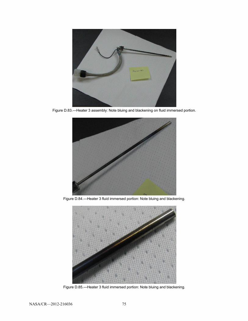
NASA/CR—2012-216036 75
Figure D.83.—Heater 3 assembly: Note bluing and blackening on fluid immersed portion.
Figure D.84.—Heater 3 fluid immersed portion: Note bluing and blackening.
Figure D.85.—Heater 3 fluid immersed portion: Note bluing and blackening.

NASA/CR—2012-216036 76
Figure D.86.—Heater 3 fluid immersed portion: Note bluing and blackening.
Figure D.87.—Heater 3 fluid immersed portion: Note bluing and blackening.
Figure D.88.—Heater 3 fluid immersed portion: Note bluing and blackening.

NASA/CR—2012-216036 77
Figure D.89.—Heater 3 fluid immersed portion: Note bluing and blackening.
Figure D.90.—Heater 3 fluid immersed portion: Note bluing and blackening.

NASA/CR—2012-216036 78
Figure D.91.—Heater 3 assembly: Note bluing and blackening on fluid immersed portion.
Figure D.92.—Heater 3 fluid immersed portion: Note bluing and blackening.

NASA/CR—2012-216036 79
Appendix E.—X-Ray Inspection PhotosThis appendix contains the photos of the cartridge heater x-ray images. See Section 4.5.3. For
Reference:Bulk Fluid Heater 1 (S/N 010) = ABulk Fluid Heater 2 (S/N 012) = BBulk Fluid Heater 3 (S/N 009) = C
Figure E.1.—Planar view of heater assemblies bulk fluid heaters of 1, 2, and 3, respectively.Note damage in heater 1.

NASA/CR—2012-216036 80
Figure E.2.—Planar view of heater assemblies bulk fluid heaters of 1, 2, and 3, respectively.Note damage in heater 1.

NASA/CR—2012-216036 81
Figure E.3.—Rotated planar view of heater assemblies bulk fluid heaters of 1, 2, and 3,respectively. Note damage in Heater 1.

NASA/CR—2012-216036 82
Figure E.4.—Close-up of Bulk Fluid Heater 1 damage at tip.

NASA/CR—2012-216036 83
Figure E.5.—Close-up of Bulk Fluid Heater 1 fitting.

NASA/CR—2012-216036 84
Figure E.6.—Close-up of Bulk Fluid Heater 1 damage along cartridge.
Figure E.7.—Close-up of Bulk Fluid Heater 1 damage along cartridge.

NASA/CR—2012-216036 85
Figure E.8.—Close-up of Bulk Fluid Heater 1 damage at tip.
Figure E.9.—Close-up of Bulk Fluid Heater 2 Tip.

NASA/CR—2012-216036 86
Figure E.10.—Wiring harness for Bulk Fluid Heater 2.
Figure E.11.—Close-up of Bulk Fluid Heater 2 along cartridge. Note irregularities in internalheater wire.
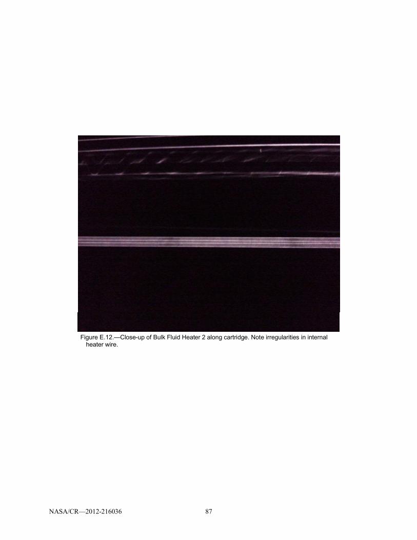
NASA/CR—2012-216036 87
Figure E.12.—Close-up of Bulk Fluid Heater 2 along cartridge. Note irregularities in internalheater wire.

NASA/CR—2012-216036 88
Figure E.13.—Close-up of Bulk Fluid Heater 2 along cartridge. Note irregularities in internalheater wire.

NASA/CR—2012-216036 89
Figure E.14.—Close-up of Bulk Fluid 3 Tip.
Figure E.15.—Close-up of Bulk Fluid Heater 3 along cartridge. Note irregularities in internalheater wire.

NASA/CR—2012-216036 90
Figure E.16.—Wiring harness for Bulk Fluid Heater 3.
Figure E.17.—Wiring harness for Bulk Fluid Heater 3.

NASA/CR—2012-216036 91
Figure E.18.—Wiring harness for Bulk Fluid Heater 3.
Figure E.19.—Wiring harness for Bulk Fluid Heater 3.

NASA/CR—2012-216036 92
Figure E.20.—Wiring harness for Bulk Fluid Heater 3.
Figure E.21.—Wiring harness for Bulk Fluid Heater 3.

NASA/CR—2012-216036 93
Figure E.22.—Close-up of Bulk Fluid Heater 3 along cartridge. Note irregularities in internalheater wire.
Figure E.23.—Close-up of Bulk Fluid Heater 3 along cartridge. Note irregularities in internalheater wire.
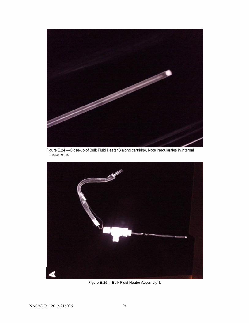
NASA/CR—2012-216036 94
Figure E.24.—Close-up of Bulk Fluid Heater 3 along cartridge. Note irregularities in internalheater wire.
Figure E.25.—Bulk Fluid Heater Assembly 1.

NASA/CR—2012-216036 95
Figure E.26.— Bulk Fluid Heater Assembly 1
Figure E.27.— Bulk Fluid Heater Assembly 1

NASA/CR—2012-216036 96
Figure E.28.— Bulk Fluid Heater Assembly 1
Figure E.29.—Bulk Fluid Heater Assembly 1.

NASA/CR—2012-216036 97
Figure E.30.—Wiring harness for Bulk Fluid Heater 1.
Figure E.31.—Wiring harness for Bulk Fluid Heater 1.

NASA/CR—2012-216036 98
Figure E.32.—Wiring harness for Bulk Fluid Heater 1.
Figure E.33.—Wiring harness for Bulk Fluid Heater 1.

NASA/CR—2012-216036 99
Figure E.34.—Wiring harness for Bulk Fluid Heater 1.
Figure E.35.—Wiring harness for Bulk Fluid Heater 1.

NASA/CR—2012-216036 100
Figure E.36.—Close-up of Bulk Fluid Heater 1 damage along cartridge.
Figure E.37.—Close-up of Bulk Fluid Heater 1 damage near cartridge tip.
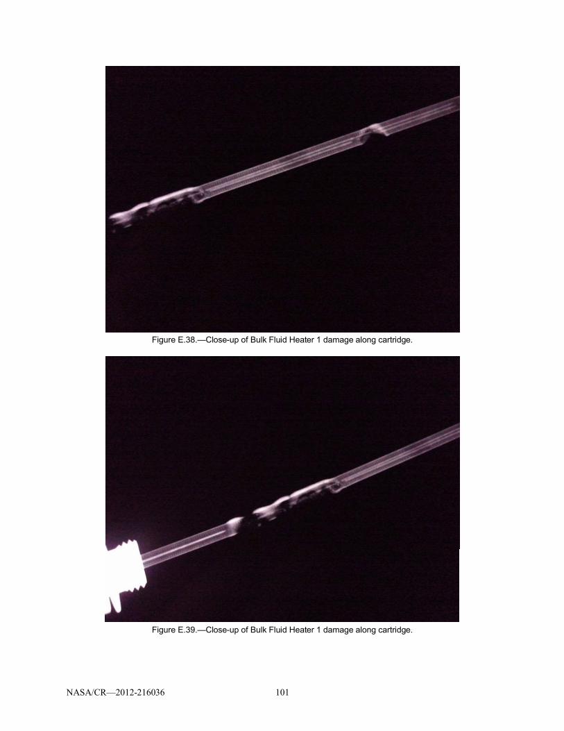
NASA/CR—2012-216036 101
Figure E.38.—Close-up of Bulk Fluid Heater 1 damage along cartridge.
Figure E.39.—Close-up of Bulk Fluid Heater 1 damage along cartridge.

NASA/CR—2012-216036 102
Figure E.40.—Close-up of Bulk Fluid Heater 1 damage along cartridge.
Figure E.41.—Planar view of heater assembly for Bulk Fluid Heater 2.

NASA/CR—2012-216036 103
Figure E.42.—Planar view of heater assembly for Bulk Fluid Heater 2.
Figure E.43.—Planar view of heater assembly for Bulk Fluid Heater 2.

NASA/CR—2012-216036 104
Figure E.44.—Wiring harness for Bulk Fluid Heater 2.
Figure E.45.—Wiring harness for Bulk Fluid Heater 2.

NASA/CR—2012-216036 105
Figure E.46.—Connector for Bulk Fluid Heater 2.
Figure E.47.—Grounding strap for Bulk Fluid Heater 2.
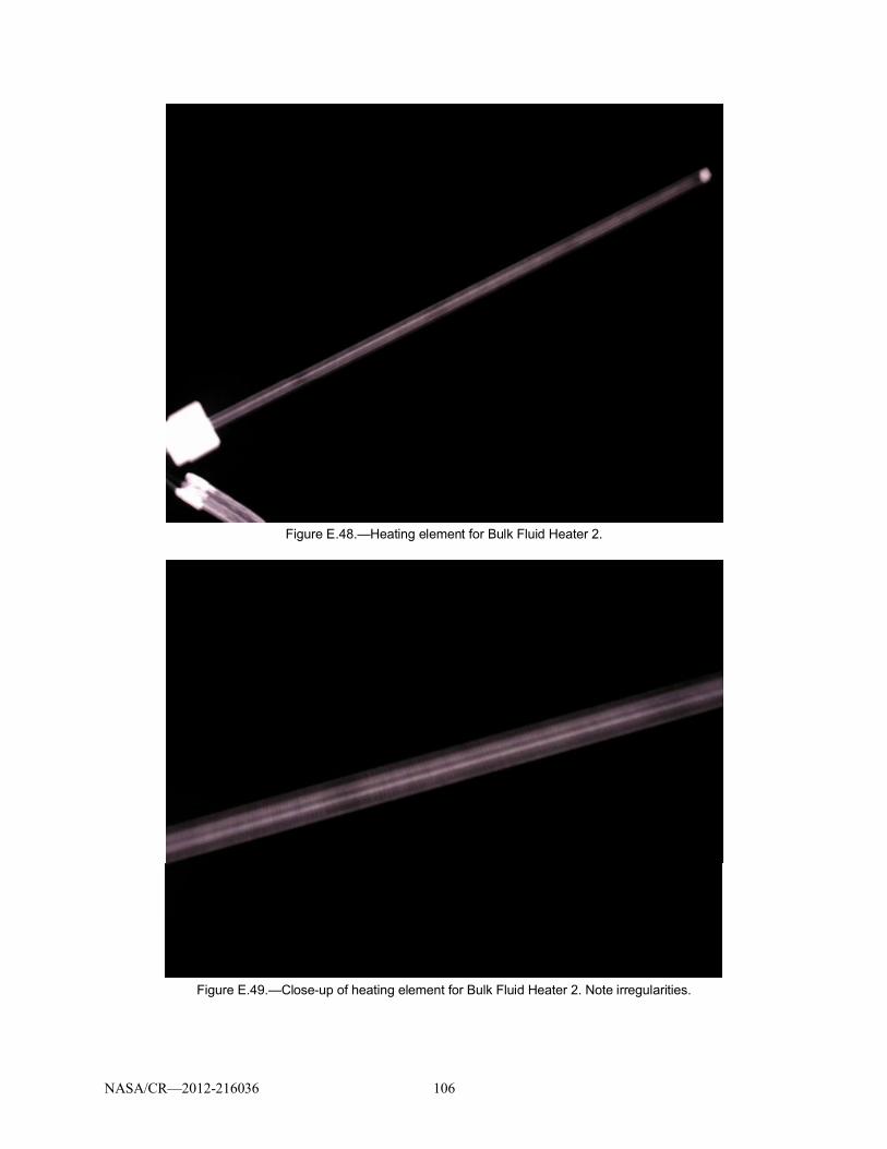
NASA/CR—2012-216036 106
Figure E.48.—Heating element for Bulk Fluid Heater 2.
Figure E.49.—Close-up of heating element for Bulk Fluid Heater 2. Note irregularities.

NASA/CR—2012-216036 107
Figure E.50.—Close-up of heating element for Bulk Fluid Heater 2. Note irregularities.
Figure E.51.—Close-up of heating element for Bulk Fluid Heater 2. Note irregularities.

NASA/CR—2012-216036 108
Figure E.52.—Close-up of heating element for Bulk Fluid Heater 2. Note irregularities.
Figure E.53.—Close-up of heating element for Bulk Fluid Heater 2. Note irregularities.

NASA/CR—2012-216036 109
Figure E.54.—Close-up of heating element for Bulk Fluid Heater 2.
Figure E.55.—Close-up of heating element for Bulk Fluid Heater 2.

NASA/CR—2012-216036 110
Figure E.56.—Close-up of heating element for Bulk Fluid Heater 2. Note irregularities.
Figure E.57.—Close-up of heating element for Bulk Fluid Heater 2. Note irregularities.

NASA/CR—2012-216036 111
Figure E.58.—Connector for Bulk Fluid Heater 2.
Figure E.59.— Close-up of end of heating element for Bulk Fluid Heater 2.

NASA/CR—2012-216036 112
Figure E.60.—Close-up of heating element for Bulk Fluid Heater 2.
Figure E.61.—Close-up of heating element for Bulk Fluid Heater 2.

NASA/CR—2012-216036 113
Figure E.62.—Close-up of heating element for Bulk Fluid Heater 2.
Figure E.63.—Connection to heating element for Bulk Fluid Heater 2.

NASA/CR—2012-216036 114
Figure E.64.—Planar view of Bulk Fluid Heater 3.
Figure E.65.—Planar view of Bulk Fluid Heater 3.
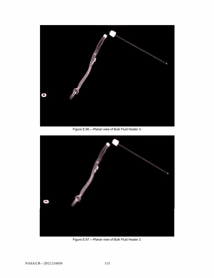
NASA/CR—2012-216036 115
Figure E.66.—Planar view of Bulk Fluid Heater 3.
Figure E.67.—Planar view of Bulk Fluid Heater 3.

NASA/CR—2012-216036 116
Figure E.68.—Wiring harness for Bulk Fluid Heater 3.
Figure E.69.—Connector for Bulk Fluid Heater 3.

NASA/CR—2012-216036 117
Figure E.70.—Grounding connection for Bulk Fluid Heater 3.
Figure E.71.—Connection to heating element for Bulk Fluid Heater 3.

NASA/CR—2012-216036 118
Figure E.72.—Heating element for Bulk Fluid Heater 3. Note irregularities.
Figure E.73.—Heating element for Bulk Fluid Heater 3. Note irregularities.

NASA/CR—2012-216036 119
Figure E.74.—Heating element for Bulk Fluid Heater 3. Note irregularities.
Figure E.75.—Heating element for Bulk Fluid Heater 3. Note irregularities.

NASA/CR—2012-216036 120
Figure E.76.—Close-up of heating element for Bulk Fluid Heater 3. Note irregularities.
Figure E.77.—Close-up of heating element for Bulk Fluid Heater 3. Note irregularities.

NASA/CR—2012-216036 121
Figure E.78.—Close-up of heating element for Bulk Fluid Heater 3. Note irregularities.

NASA/CR—2012-216036 122
Figure E.79.—Close-up of heating element for Bulk Fluid Heater 3. Note irregularities.
Figure E.80.—Close-up of heating element for Bulk Fluid Heater 3. Note irregularities.

NASA/CR—2012-216036 123
Figure E.81.—Wiring harness for Bulk Fluid Heaters.

NASA/CR—2012-216036 124
Figure E.82.— Wiring harness for Bulk Fluid Heaters.
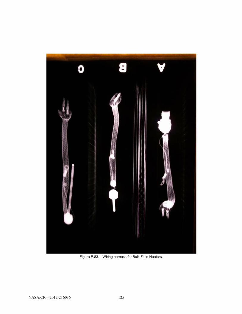
NASA/CR—2012-216036 125
Figure E.83.—Wiring harness for Bulk Fluid Heaters.

NASA/CR—2012-216036 126
Figure E.84.— Power connection to heating element for Bulk Fluid Heater 1.

NASA/CR—2012-216036 127
Figure E.85.—Power connection to heating element for Bulk Fluid Heater 1.

NASA/CR—2012-216036 128
Figure E.86.—Grounding connection for Bulk Fluid Heater 1.

NASA/CR—2012-216036 129
Figure E.87.—Power connectors for Bulk Fluid Heater 1.

NASA/CR—2012-216036 130
Figure E.88.—Harness connection for Bulk Fluid Heater 2.

NASA/CR—2012-216036 131
Figure E.89.—Power connection for Bulk Fluid Heater 2.

NASA/CR—2012-216036 132
Figure E.90.—Power connection for Bulk Fluid Heater 2.

NASA/CR—2012-216036 133
Figure E.91.—Wiring harness for Bulk Fluid Heater 2.

NASA/CR—2012-216036 134
Figure E.92.—Power connection to heating element for Bulk Fluid Heater 2.

NASA/CR—2012-216036 135
Figure E.93.—Power connection for Bulk Fluid Heater 3.
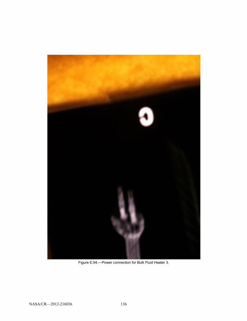
NASA/CR—2012-216036 136
Figure E.94.—Power connection for Bulk Fluid Heater 3.

NASA/CR—2012-216036 137
Figure E.95.—Grounding connection for Bulk Fluid Heater 3.

NASA/CR—2012-216036 138
Figure E.96.—Power connection to heating element for Bulk Fluid Heater 3.

NASA/CR—2012-216036 139
Figure E.97.—Grounding connection for Bulk Fluid Heater 3.

NASA/CR—2012-216036 140
Figure E.98.—Power connection to heating element for Bulk Fluid Heater 3.

NASA/CR—2012-216036 141
Appendix F.—Approvals
Prepared by: /s/ Wendell H. Booth Date: 04/05/12Wendell H. BoothZIN Technologies, Inc.BXF Lead Electrical Engineer
Reviewed by: /s/ Kevin S. Magee Date: 04/05/12Kevin S. MageeZIN Technologies, Inc.BXF Lead Mechanical Engineer
Reviewed by: /s/ Russell W. Valentine Date: 04/05/12Russell W. ValentineZIN Technologies, Inc.BXF Mechanical Engineer
Reviewed by: /s/ Craig A. Totman Date: 04/05/12
Craig A. TotmanZIN Technologies, Inc.Mechanical Engineer
Reviewed by: /s/ Christian T. Lant Date: 04/05/12Christian T. LantZIN Technologies, Inc.BXF Optics Engineer
Reviewed by: /s/ Jim Bruewer Date: 04/06/12Jim BruewerZIN Technologies, Inc.Manufacturing Manager
Reviewed by: /s/ Debra R. Lyden Date: 04/06/12Debra R. LydenZIN Technologies, Inc.Quality/Safety Manager
NASA/CR—2012-216036 142
Approvals.—Continued
Approved by: /s/ Raymond K. Pavlik Date: 04/06/12Raymond K. PavlikZIN Technologies, Inc.BXF Project Lead
Accepted by: /s/ William A. Sheredy Date: 04/11/12William A. SheredyNASA Glenn Research CenterBXF Project Manager

NASA/CR—2012-216036 143
Appendix G.—Revisions
RevisionLetter
PublicationDate
Change Description Approval
- 04/2012 Baseline Release

NASA/CR—2012-216036 144
Reference1. “Rainey, K. N. and You, S. M., “Boiling heat transfer phenomena from microporous and porous
surfaces in saturated FC-72,” International Journal of Heat and Mass Transfer, Vol. 40, pp. 4437–4447, 1997,


![Flow boiling heat transfer of HFO1234yf and HFC32 ... boiling heat transfer of... · boiling heat transfer coefficient is calculated from the pool boiling correlation of Cooper [7]](https://img.pdfslide.us/doc/110x75/6060f16e796df51c036c4972/flow-boiling-heat-transfer-of-hfo1234yf-and-hfc32-boiling-heat-transfer-of.jpg)