Embed Size (px)
Citation preview
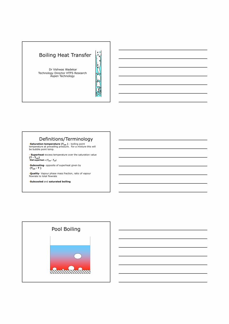
Boiling Heat Transfer
Dr Vishwas Wadekar
Technology Director HTFS Research Aspen Technology
Definitions/Terminology�Saturation temperature (Tsat ) - boiling point temperature at prevailing pressure. For a mixture this will be bubble point temp.
� Superheat-excess temperature over the saturation value (T - Tsat)•Wall superheat = (Twall - Tsat)
�Subcooling- opposite of superheat given by (Tsat - T )
�Quality- Vapour phase mass fraction, ratio of vapour flowrate to total flowrate
�Subcooled and saturated boiling
Pool Boiling
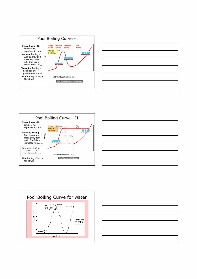
Pool Boiling Curve - I
Single
Phase
Nucleate
Boiling
Transition
Boiling
Film
Boiling
LOG Wall Superheat ( Tw - Tsat )
LO
G (
q)
Critical
heat flux
(Wall temperature controlled case)
Single Phase - No
bubbles, wall superheat too low
Nucleate Boiling -Bubbles grow and
break away from wall. Coefficient
increases with ∆Tsat
Transition Boiling -Localised dry
patches on the wall
Film Boiling - Vapour film at wall
Pool Boiling Curve - II
Single
Phase
Nucleate
Boiling
Transition
Boiling
Film
Boiling
LOG Wall Superheat ( Tw - Tsat )
LO
G (
q)
Critical
heat flux
(Heat flux controlled case)
Single Phase - No
bubbles, wall superheat too low
Nucleate Boiling -
Bubbles grow and break away from
wall. Coefficient
increases with ∆Tsat
Transition Boiling -Localised dry
patches on the wall
Film Boiling - Vapour film at wall
Pool Boiling Curve for water
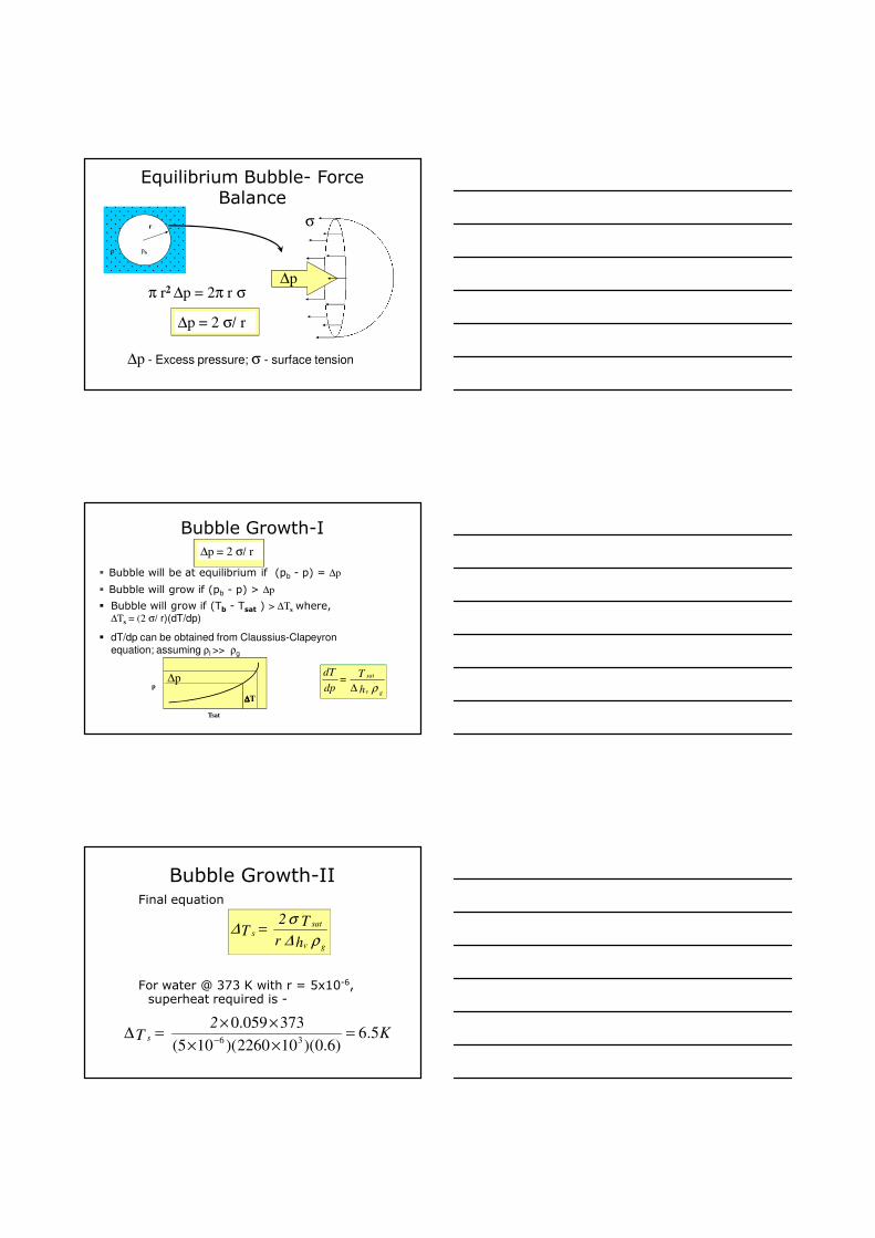
Equilibrium Bubble- Force Balance
r
π r2 ∆p = 2π r σ
∆p = 2 σ/ r
σ
∆p
∆p - Excess pressure; σ - surface tension
p pb
Bubble Growth-I
� Bubble will be at equilibrium if (pb - p) = ∆p
� Bubble will grow if (pb - p) > ∆p
ρ gv
sat
h
T =
dp
dT
∆∆p
∆∆∆∆T
Tsat
p
∆p = 2 σ/ r
� Bubble will grow if (Tb - Tsat ) > ∆Τs where,∆Ts = (2 σ/ r)(dT/dp)
� dT/dp can be obtained from Claussius-Clapeyron
equation; assuming ρl >> ρg
Bubble Growth-IIFinal equation
For water @ 373 K with r = 5x10⁻⁶, superheat required is -
ρ∆
σ∆
gv
sats
h r
T 2 T =
K2
T s 5.6)6.0)(102260)(105(
373059.036
=××
××=∆
−
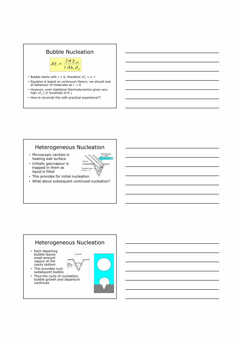
Bubble Nucleation
� Bubble starts with r = 0, therefore ∆Ts = α !!
� Equation is based on continuum theory; we should look at behaviour of molecules as r → 0
� However, even statistical thermodynamics gives very high ∆Ts ( in hundreds of K )
� How to reconcile this with practical experience??
ρ∆
σ∆
gv
sats
h r
T 2 T =
Heterogeneous Nucleation
• Microscopic cavities in heating wall surface
• Initially gas/vapour is trapped in them as liquid is filled
• This provides for initial nucleation
• What about subsequent continued nucleation?
Heterogeneous Nucleation
• Each departing bubble leaves small amount vapour at the cavity bottom
• This provides nucleation for subsequent bubble
• Thus the cycle of nucleation, bubble growth and departure continues
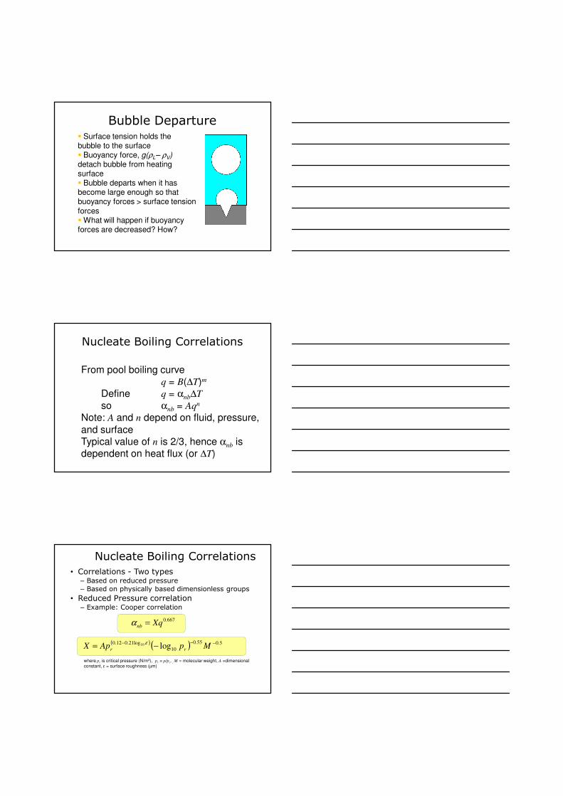
Bubble Departure� Surface tension holds the bubble to the surface� Buoyancy force, g(ρL– ρV)detach bubble from heating surface � Bubble departs when it has become large enough so that buoyancy forces > surface tension
forces� What will happen if buoyancy forces are decreased? How?
Nucleate Boiling Correlations
From pool boiling curveq = B(∆T)m
Define q = αnb∆T
so αnb = Aqn
Note: A and n depend on fluid, pressure,
and surfaceTypical value of n is 2/3, hence αnb is dependent on heat flux (or ∆T)
Nucleate Boiling Correlations
• Correlations - Two types– Based on reduced pressure
– Based on physically based dimensionless groups
• Reduced Pressure correlation– Example: Cooper correlation
667.0Xqnb =α
where pc is critical pressure (N/m2), pr = p/pc, , M = molecular weight, A =dimensional
constant, ε = surface roughness (µm)
( )( ) 5.055.0
10
log21.012.0log10 −−−
−= MpApX rr
ε
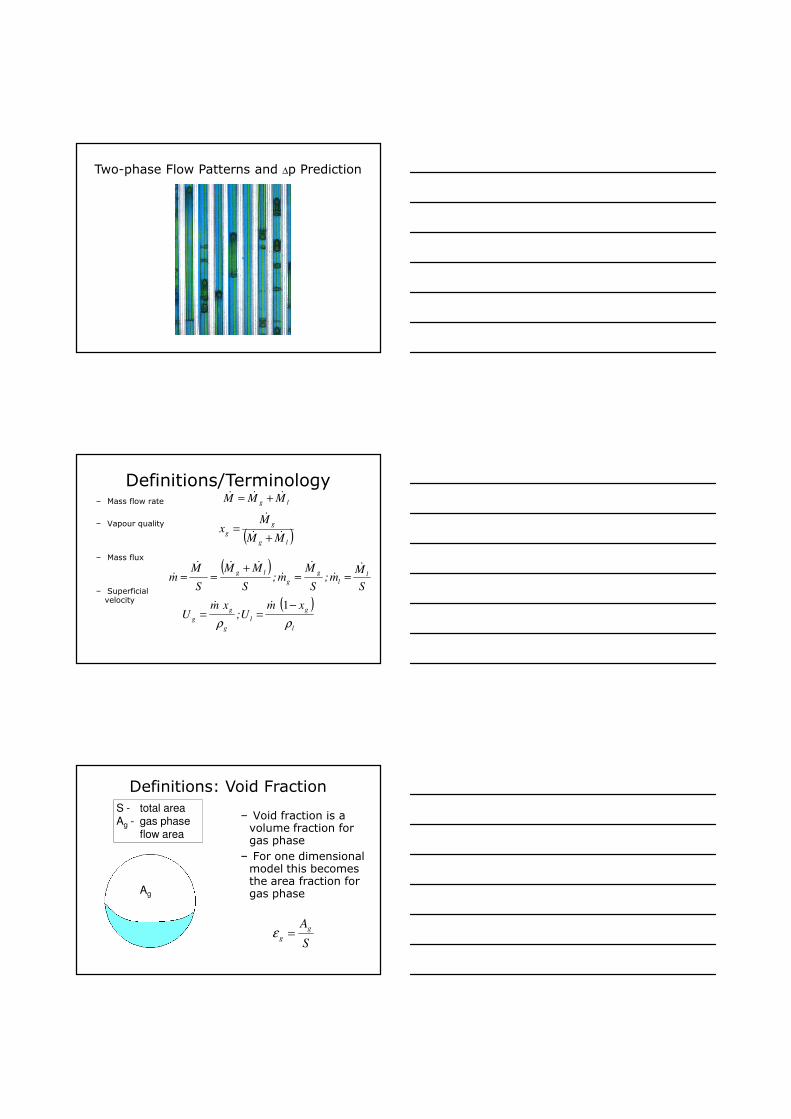
Two-phase Flow Patterns and ∆p Prediction
Definitions/Terminologylg MMM &&& +=
( )lg
g
gMM
Mx
&&
&
+=
( )S
Mm;
S
Mm;
S
MM
S
Mm l
l
g
g
lg&
&
&
&
&&&
& ==+
==
( )
l
g
l
g
g
g
xmU;
xmU
ρρ
−==
1&&
– Mass flow rate
– Vapour quality
– Mass flux
– Superficial velocity
Definitions: Void Fraction
– Void fraction is a volume fraction for gas phase
– For one dimensional model this becomes the area fraction for gas phaseAg
S - total area Ag - gas phase
flow area
S
Ag
g =ε
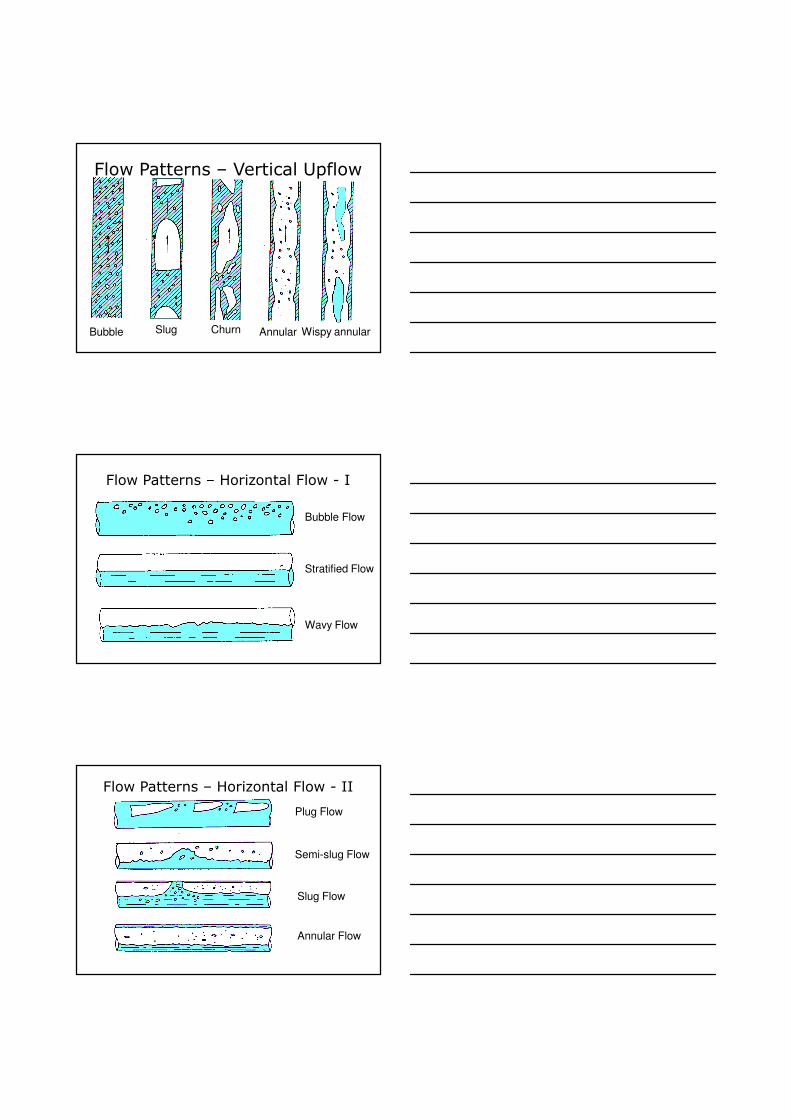
Flow Patterns – Vertical Upflow
Bubble Slug Churn Annular Wispy annular
Flow Patterns – Horizontal Flow - I
Bubble Flow
Stratified Flow
Wavy Flow
Flow Patterns – Horizontal Flow - II
Annular Flow
Slug Flow
Plug Flow
Semi-slug Flow
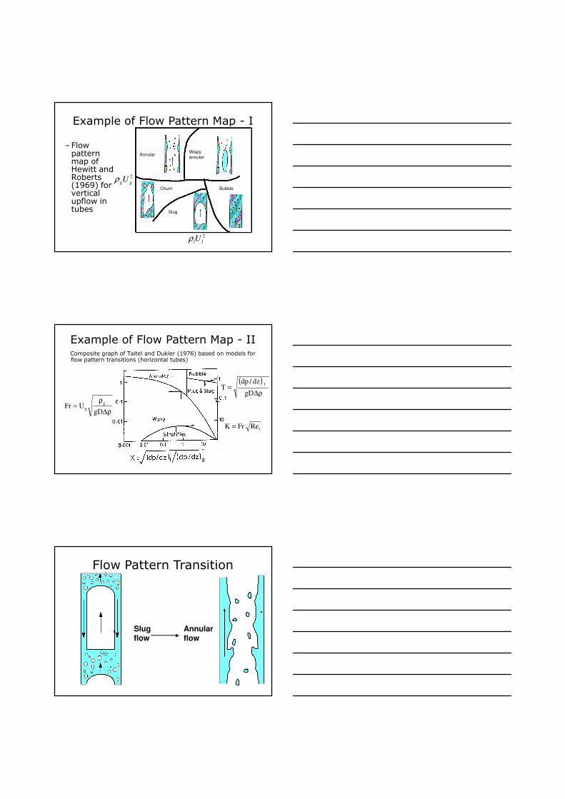
Example of Flow Pattern Map - I
–Flow pattern map of Hewitt and Roberts (1969) for vertical upflow in tubes
2
llUρ
2
ggUρ
AnnularWispy
annular
Churn
Slug
Bubble
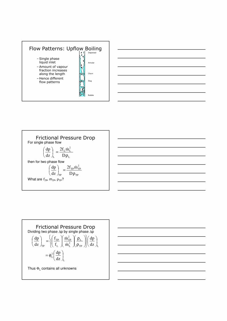
Example of Flow Pattern Map - IIComposite graph of Taitel and Dukler (1976) based on models for flow pattern transitions (horizontal tubes)
ρ∆
ρ=
gDUFr
g
g
( )
ρ∆=
gD
dz/dpT
l
lReFrK =00
.1
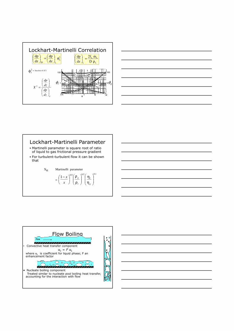
Flow Pattern Transition
Slug flow
Annular flow
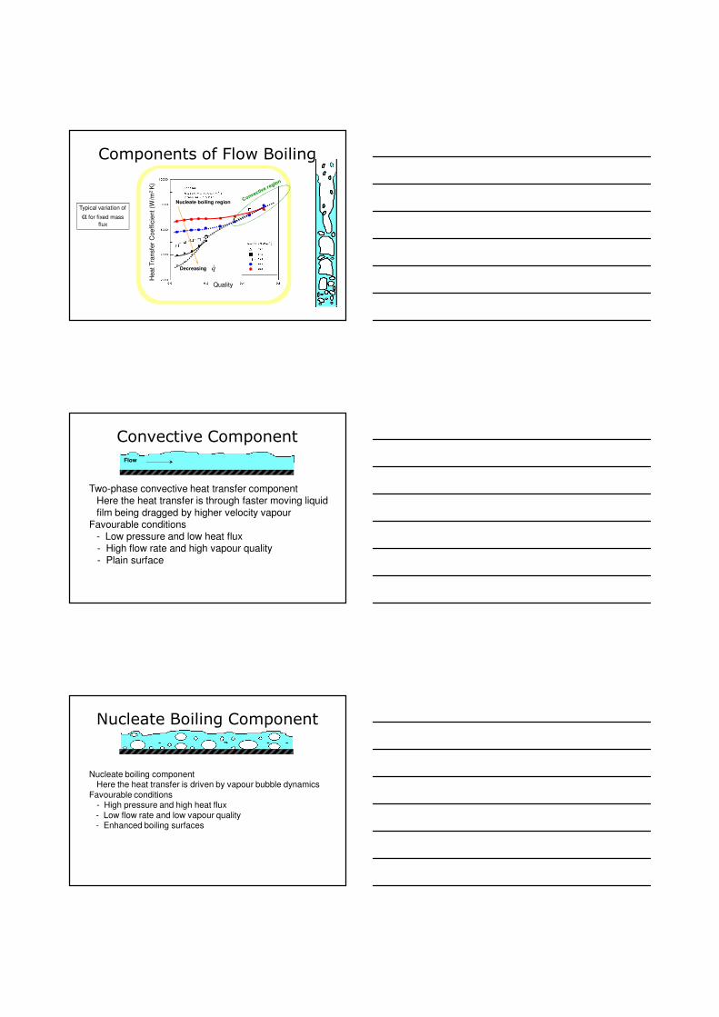
Flow Patterns: Upflow Boiling
Annular
Churn
Slug
Bubble
Dispersed
–Single phase liquid inlet
–Amount of vapour fraction increases along the length
–Hence different flow patterns
Frictional Pressure Drop
L
2
LL
L D
mf2
dz
dp
ρ=
&
TP
2
TPTP
TP D
mf2
dz
dp
ρ=
&
For single phase flow
then for two phase flow
What are fTP, mTP, ρTP?
Frictional Pressure Drop
LTP
L
2
L
2
TP
L
TP
TP dz
dp
m
m
f
f
dz
dp
ρ
ρ
=
&
&
Dividing two phase ∆p by single phase ∆p
Thus ΦL contains all unknowns
L
2
Ldz
dp
φ=
Lockhart-Martinelli Correlation2
L
LTP dz
dp
dz
dpφ
=
L
LL
L D
mf2
dz
dp
ρ=
&
= function of (X2)2
lφ
g
l
dz
dp
dz
dp
X
=2
φl φg
100
X
100
Lockhart-Martinelli Parameter• Martinelli parameter is square root of ratio of liquid to gas frictional pressure gradient
• For turbulent-turbulent flow it can be shown that
Xtt Martinelli parameter
=
1.05.09.01
η
η
ρ
ρ
−
g
l
l
g
x
x
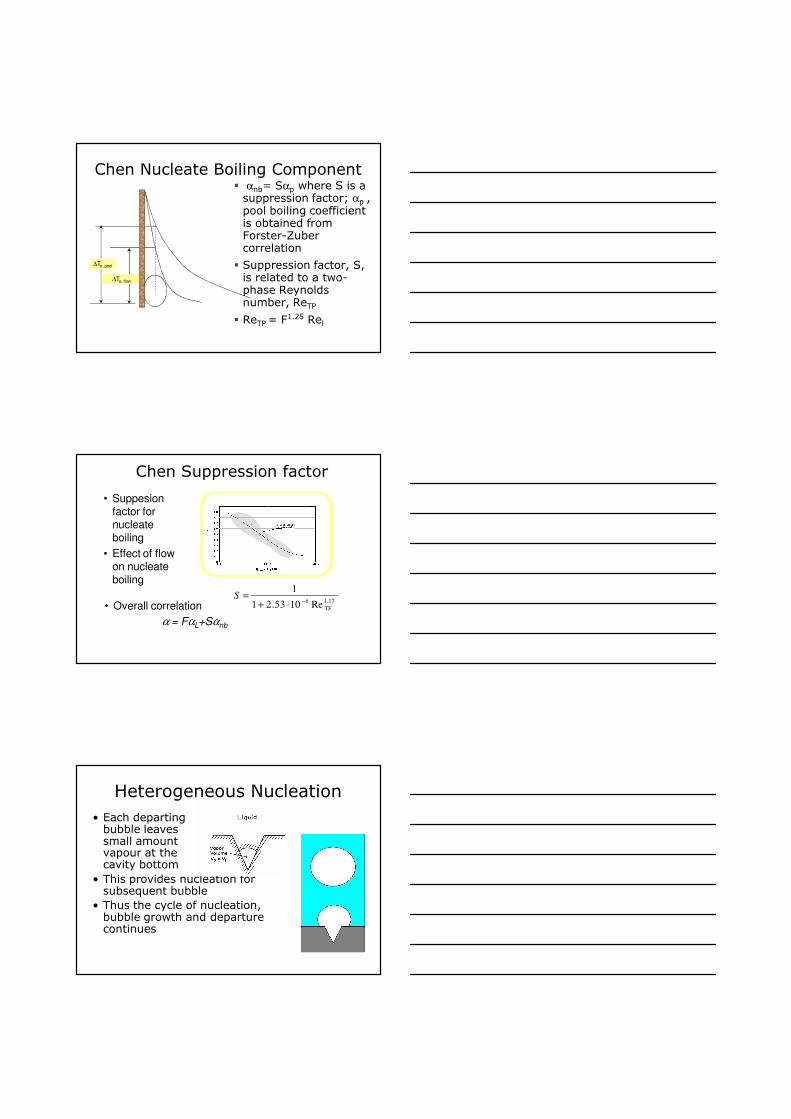
Flow Boiling
• Convective heat transfer component
αc = F αLwhere αL is coefficient for liquid phase; F an enhancement factor
•• Nucleate boiling component
Treated similar to nucleate pool boiling heat transfer, accounting for the interaction with flow
Flow
Components of Flow Boiling
Typical variation of
α for fixed mass
flux
Quality
Heat Tra
nsfe
r C
oeff
icie
nt (W
/m2K
)
Nucleate boiling region
Decreasing q&
Convective Component
Two-phase convective heat transfer componentHere the heat transfer is through faster moving liquid
film being dragged by higher velocity vapour Favourable conditions
- Low pressure and low heat flux- High flow rate and high vapour quality- Plain surface
Flow
Nucleate Boiling Component
Nucleate boiling componentHere the heat transfer is driven by vapour bubble dynamics
Favourable conditions- High pressure and high heat flux
- Low flow rate and low vapour quality- Enhanced boiling surfaces
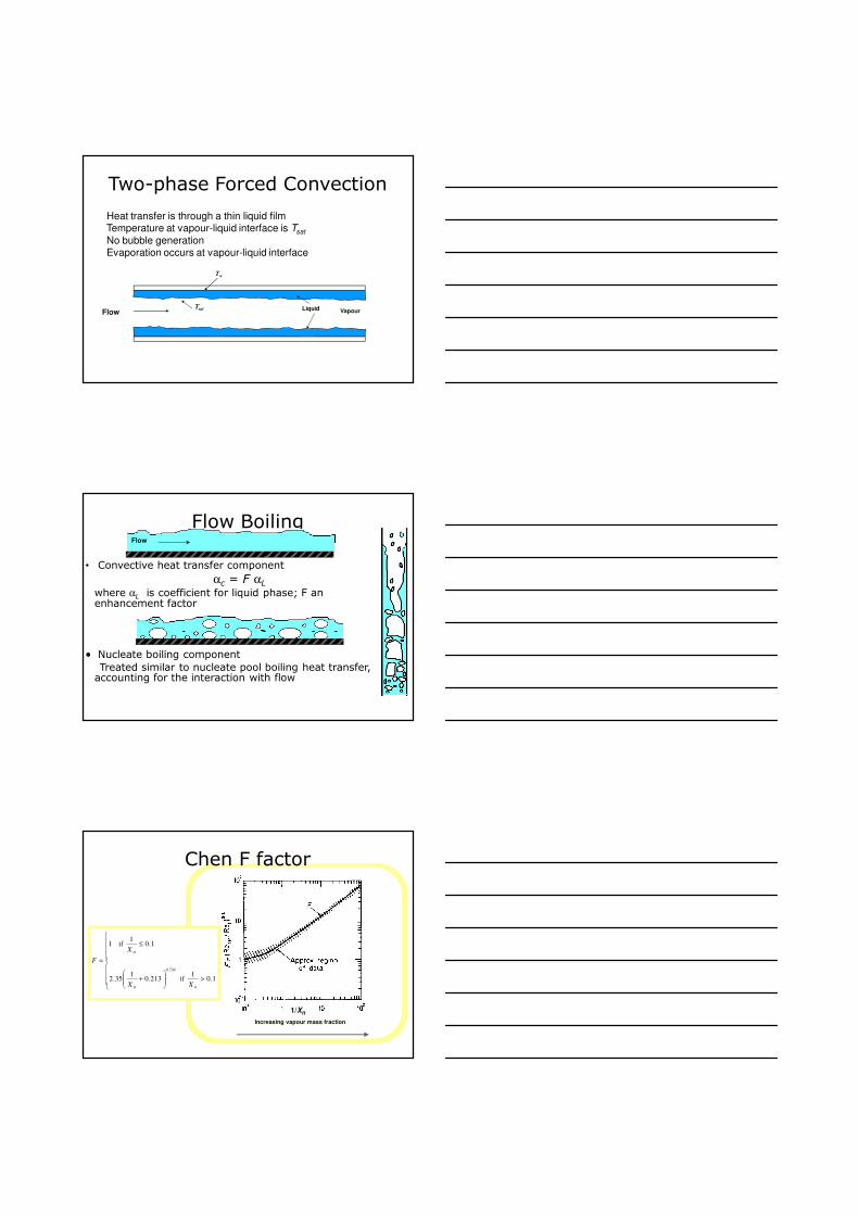
Two-phase Forced Convection
Heat transfer is through a thin liquid filmTemperature at vapour-liquid interface is Tsat
No bubble generationEvaporation occurs at vapour-liquid interface
Tsat
Tw
Flow
Liquid
VapourLiquid
Flow Boiling
• Convective heat transfer component
αc = F αLwhere αL is coefficient for liquid phase; F an enhancement factor
•• Nucleate boiling component
Treated similar to nucleate pool boiling heat transfer, accounting for the interaction with flow
Flow
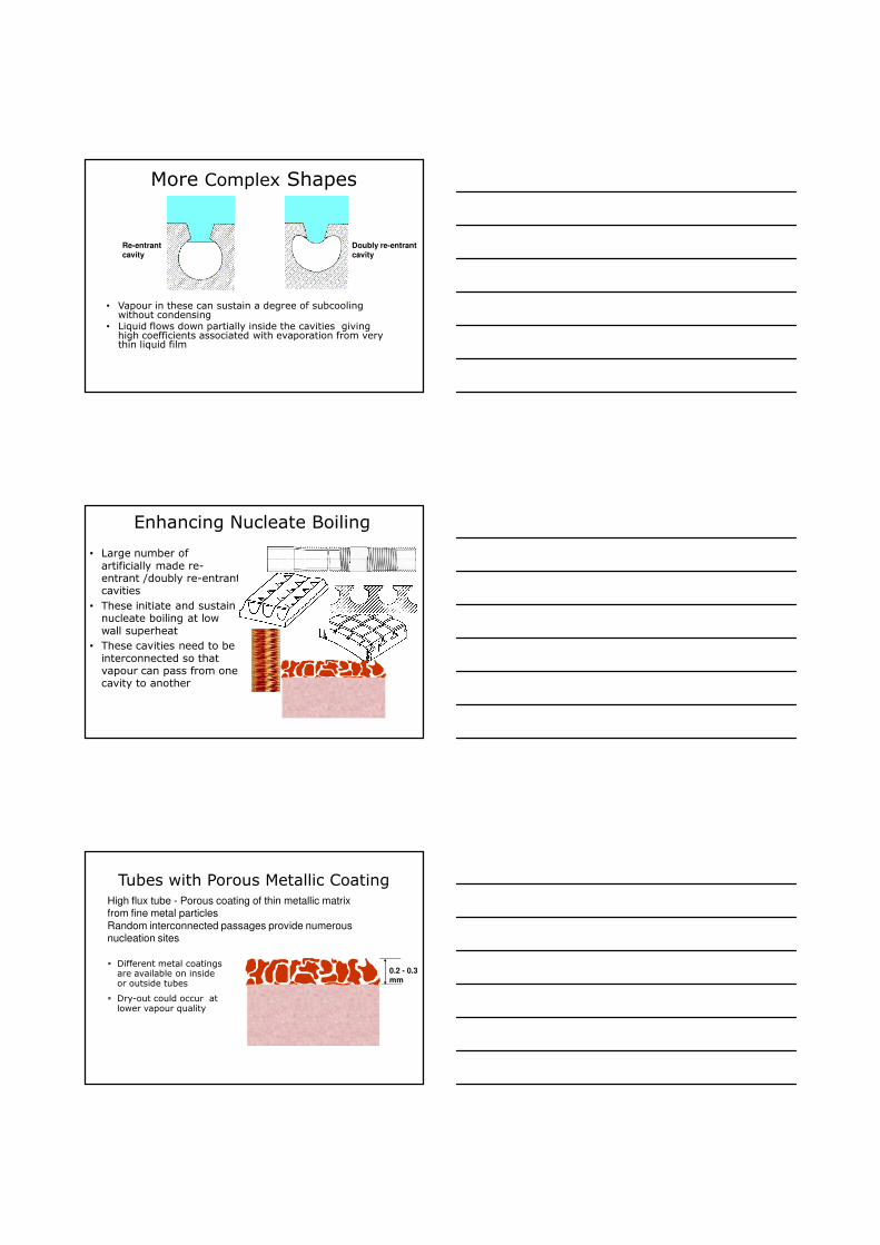
Increasing vapour mass fraction
1/Xtt
Chen F factor
>
+
≤
=
1.01
if 213.01
35.2
1.01
if 1
tt
736.0
tt
tt
XX
X
F
Chen Nucleate Boiling Component� αnb= Sαp where S is a suppression factor; αp , pool boiling coefficient is obtained from Forster-Zuber correlation
� Suppression factor, S, is related to a two-phase Reynolds number, ReTP
� ReTP = F1.25 Rel
∆Te, pool
∆Te, flow
Chen Suppression factor
• Suppesion factor for nucleate boiling
• Effect of flow on nucleate boiling
1.17
TF
6Re1053.21
1−
⋅+=S
• Overall correlation
α = FαL+Sαnb
Heterogeneous Nucleation
• Each departing bubble leaves small amount vapour at the cavity bottom
• This provides nucleation for subsequent bubble
• Thus the cycle of nucleation, bubble growth and departure continues
More Complex Shapes
• Vapour in these can sustain a degree of subcoolingwithout condensing
• Liquid flows down partially inside the cavities giving high coefficients associated with evaporation from very thin liquid film
Re-entrant
cavity
Doubly re-entrant
cavity
Enhancing Nucleate Boiling
• Large number of artificially made re-entrant /doubly re-entrant cavities
• These initiate and sustain nucleate boiling at low wall superheat
• These cavities need to be interconnected so that vapour can pass from one cavity to another
Tubes with Porous Metallic CoatingHigh flux tube - Porous coating of thin metallic matrix from fine metal particles
Random interconnected passages provide numerousnucleation sites
0.2 - 0.3
mm
� Different metal coatings are available on inside or outside tubes
� Dry-out could occur at lower vapour quality
Results with Composite Test-section
Composite test-section for in-tube boiling
Three parts of the test-sectionElectrical resistance heatingDetailed thermal measurements
Results with and without enhancement device can be directly compared for single phase and flow boiling heat transfer
Same mass fluxSame heat fluxNearly same pressure
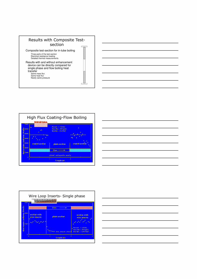
0
10000
20000
30000
40000
50000
60000
70000
0 1 2 3
Length (m)
Heat
tran
sfer c
oeff
icie
nt
(W/m
2K
) Pressure = 1.66 bar
Mass flux = 285 kg/m2s
Heat flux = 41 kW/m2
coated section plain section
Flow
coated section
High Flux Coating-Flow Boiling
Wire Loop Inserts- Single phase
0
10 00
20 00
30 00
0 1 2 3
Length (m)
Hea
t tr
an
sfer
coef
fici
ent
(W/m
2K
)
Pressure = 1.44 bar
M ass flux = 287 kg/m2s
Heat flux = 2.59 kW/m2
section with
wire insertssection with
wire insertsplain section
F low
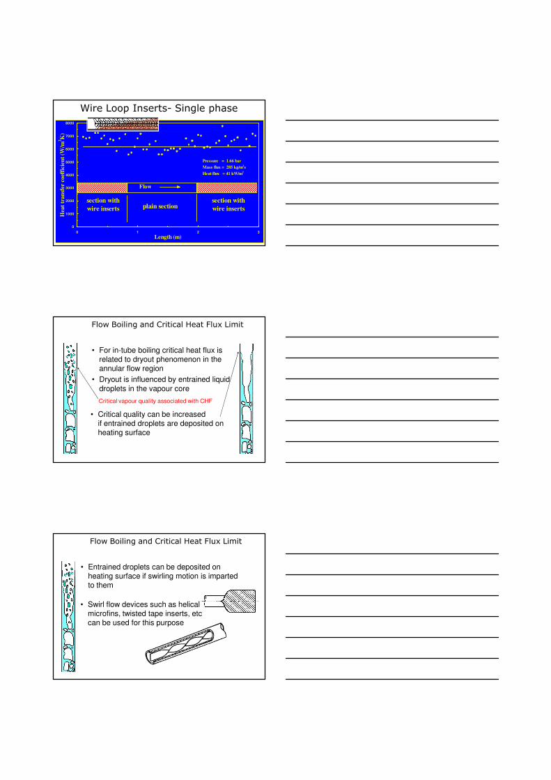
Wire Loop Inserts- Single phase
0
1000
2000
3000
4000
5000
6000
7000
8000
0 1 2 3
Length (m)
Hea
t tr
an
sfer
coef
fici
ent
(W/m
2K
)
Pressure = 1.66 bar
Mass flux = 285 kg/m2s
Heat flux = 41 kW/m2
section with
wire inserts
section with
wire insertsplain section
Flow
• For in-tube boiling critical heat flux is related to dryout phenomenon in the annular flow region
• Dryout is influenced by entrained liquid
droplets in the vapour core
Flow Boiling and Critical Heat Flux Limit
Critical vapour quality associated with CHF
• Critical quality can be increased if entrained droplets are deposited on heating surface
• Entrained droplets can be deposited on heating surface if swirling motion is imparted to them
Flow Boiling and Critical Heat Flux Limit
• Swirl flow devices such as helical microfins, twisted tape inserts, etc can be used for this purpose


![A study on film boiling using a Coupled Level Set · growth in Film Boiling. Son and Dhir [10] simulated film boiling on a horizontal surface, solving governing equations for both](https://img.pdfslide.us/doc/110x75/5e6f3a4dac3fa621a44d3e37/a-study-on-film-boiling-using-a-coupled-level-set-growth-in-film-boiling-son-and.jpg)
![A study on film boiling using a Coupled Level Setgrowth in Film Boiling. Son and Dhir [10] simulated film boiling on a horizontal surface, solving governing equations for both liquid](https://img.pdfslide.us/doc/110x75/5e6f3ea98fb2d905a90386f5/a-study-on-film-boiling-using-a-coupled-level-growth-in-film-boiling-son-and-dhir.jpg)