Embed Size (px)
Citation preview
Version 1.0Revision AJuly 2015
Reference Guide
Bison DR + GNSS Receiver
For use with:Bison DR + GNSS receiver, P/N 99988-XX
BISON DR + GNSS RECEIVER REFERENCE GUIDE 2
Legal NoticesCorporate OfficeTrimble Navigation Limited Embedded / IVN Division 935 Stewart Drive Sunnyvale, CA 94085 U.S.A. Phone: 1-800-767-4822 +1-408-481-8258www.trimble.com
Support OfficesTrimble Navigation Limited Embedded / IVN Division 935 Stewart Drive Sunnyvale, CA 94085 U.S.A. Phone: 1-800-767-4822
Copyright and Trademarks© 1997–2015, Trimble Navigation Limited.Trimble, the Globe & Triangle logo, Condor, and OmniSTAR are trademarks of Trimble Navigation Limited, registered in the United States and in other countries. All other trademarks are the property of their respective owners.All rights reserved. No part of this manual may be copied, reproduced, translated, or reduced to any electronic medium or machine-readable form for any use other than with the Bison DR + GNSS device.
Release NoticeThis is the July 2015 release (Revision A) of the Bison DR + GNSS Receiver Reference Guide, part number 99988-XX-UG. This reference guide is intended for use by system integrators, service providers, and application developers (“resellers”). It is not intended for end-users of the device. It is the responsibility of resellers to develop and provide end-user documentation.
LIMITED WARRANTY TERMS AND CONDITIONS
Product Limited WarrantySubject to the following terms and conditions, Trimble Navigation Limited (“Trimble”) warrants that for a period of one (1) year from date of purchase this Trimble product (the “Product”) will substantially conform to Trimble's publicly available specifications for the Product and that the hardware and any storage media components of the Product will be substantially free from defects in materials and workmanship. THIS PRODUCT LIMITED WARRANTY IS PROVIDED TO RESELLERS AND TO RESELLERS ONLY. THE RESELLER IS SOLELY RESPONSIBLE FOR ANY AND ALL WARRANTIES MADE TO ITS CUSTOMERS, AND TRIMBLE MAKES NO WARRANTIES, EXPRESS OR IMPLIED, AND SHALL HAVE NO OBLIGATIONS OR LIABILITY TO RESELLER'S CUSTOMERS OR END-USERS OF THE PRODUCT. RESELLER SHALL NOT MAKE ANY REPRESENTATIONS OR WARRANTIES ON TRIMBLE'S BEHALF, AND SHALL FULLY INDEMNIFY, DEFEND AND HOLD TRIMBLE HARMLESS FROM ANY BREACH OF THE FOREGOING.IF RESELLER DISTRIBUTES PRODUCT TO END-USER CUSTOMERS, RESELLER SHALL BE SOLELY RESPONSIBLE FOR PREPARING AND PROVIDING PRODUCT WARRANTIES AND PRODUCT LITERATURE TO END-USERS.
Warranty RemediesIf the Trimble Product fails during the warranty period for reasons covered by this limited warranty and you notify Trimble of such failure during the warranty period, Trimble will repair OR replace the nonconforming Product with new, equivalent to new, or reconditioned parts or Product, OR refund the Product purchase price paid by you, at Trimble’s option, upon your return of the Product in accordance with Trimble's product return procedures then in effect.
How to Obtain Warranty ServiceTo obtain warranty service for the Product, please contact your local Trimble authorized dealer. Alternatively, you may contact Trimble to request warranty service at +1-408-481-6940 (24 hours a day) or e-mail your request to [email protected]. Please be prepared to provide: – your name, address, and telephone numbers
– proof of purchase– a copy of this Trimble warranty– a description of the nonconforming Product including the model
number– an explanation of the problemThe customer service representative may need additional information from you depending on the nature of the problem.
Warranty Exclusions and DisclaimerThis Product limited warranty shall only apply in the event and to the extent that (a) the Product is properly and correctly installed, configured, interfaced, maintained, stored, and operated in accordance with Trimble's applicable operator's manual and specifications, and; (b) the Product is not modified or misused. This Product limited warranty shall not apply to, and Trimble shall not be responsible for, defects or performance problems resulting from (i) the combination or utilization of the Product with hardware or software products, information, data, systems, interfaces, or devices not made, supplied, or specified by Trimble; (ii) the operation of the Product under any specification other than, or in addition to, Trimble's standard specifications for its products; (iii) the unauthorized installation, modification, or use of the Product; (iv) damage caused by: accident, lightning or other electrical discharge, fresh or salt water immersion or spray (outside of Product specifications); or exposure to environmental conditions for which the Product is not intended; (v) normal wear and tear on consumable parts (e.g., batteries); or (vi) cosmetic damage. Trimble does not warrant or guarantee the results obtained through the use of the Product, or that software components will operate error free. NOTICE REGARDING PRODUCTS EQUIPPED WITH TECHNOLOGY CAPABLE OF TRACKING SATELLITE SIGNALS FROM SATELLITE BASED AUGMENTATION SYSTEMS (SBAS) (WAAS/EGNOS, AND MSAS), OMNISTAR, GNSS, MODERNIZED GNSS OR GLONASS SATELLITES, OR FROM IALA BEACON SOURCES: TRIMBLE IS NOT RESPONSIBLE FOR THE OPERATION OR FAILURE OF OPERATION OF ANY SATELLITE BASED POSITIONING SYSTEM OR THE AVAILABILITY OF ANY SATELLITE BASED POSITIONING SIGNALS.THE FOREGOING LIMITED WARRANTY TERMS STATE TRIMBLE’S ENTIRE LIABILITY, AND YOUR EXCLUSIVE REMEDIES, RELATING TO THE TRIMBLE PRODUCT. EXCEPT AS OTHERWISE EXPRESSLY PROVIDED HEREIN, THE PRODUCT, AND ACCOMPANYING DOCUMENTATION AND MATERIALS ARE PROVIDED “AS-IS” AND WITHOUT EXPRESS OR IMPLIED WARRANTY OF ANY KIND, BY EITHER TRIMBLE OR ANYONE WHO HAS BEEN INVOLVED IN ITS CREATION, PRODUCTION, INSTALLATION, OR DISTRIBUTION, INCLUDING, BUT NOT LIMITED TO, THE IMPLIED WARRANTIES OF MERCHANTABILITY AND FITNESS FOR A PARTICULAR PURPOSE, TITLE, AND NONINFRINGEMENT. THE STATED EXPRESS WARRANTIES ARE IN LIEU OF ALL OBLIGATIONS OR LIABILITIES ON THE PART OF TRIMBLE ARISING OUT OF, OR IN CONNECTION WITH, ANY PRODUCT. BECAUSE SOME STATES AND JURISDICTIONS DO NOT ALLOW LIMITATIONS ON DURATION OR THE EXCLUSION OF AN IMPLIED WARRANTY, THE ABOVE LIMITATION MAY NOT APPLY OR FULLY APPLY TO YOU.
Embedded Software/FirmwareThe Product and associated tools, if any, may contain embedded software/firmware, which is licensed, not sold, and is only for use within the Product as an integral part thereof. Such embedded software/firmware (which includes all updates thereto) contains valuable trade secrets and is proprietary to Trimble and its suppliers. To the greatest extent permitted by law, such embedded software/firmware may not be modified, copied, disassembled, decompiled or reverse engineered. Trimble reserves all other rights.
Limitation of Liability TRIMBLE'S ENTIRE LIABILITY UNDER ANY PROVISION HEREIN SHALL BE LIMITED TO THE AMOUNT PAID BY YOU FOR THE PRODUCT. TO THE MAXIMUM EXTENT PERMITTED BY APPLICABLE LAW, IN NO EVENT SHALL TRIMBLE OR ITS SUPPLIERS BE LIABLE FOR ANY INDIRECT, SPECIAL, INCIDENTAL, OR CONSEQUENTIAL DAMAGE WHATSOEVER UNDER ANY CIRCUMSTANCE OR LEGAL THEORY RELATING IN ANYWAY TO THE PRODUCTS, SOFTWARE AND ACCOMPANYING DOCUMENTATION AND MATERIALS, (INCLUDING, WITHOUT LIMITATION, DAMAGES FOR LOSS OF BUSINESS PROFITS, BUSINESS INTERRUPTION, LOSS OF DATA, OR ANY OTHER PECUNIARY LOSS), REGARDLESS OF WHETHER TRIMBLE HAS BEEN ADVISED OF THE POSSIBILITY OF ANY SUCH LOSS AND REGARDLESS OF THE COURSE OF DEALING WHICH DEVELOPS OR HAS DEVELOPED BETWEEN YOU AND TRIMBLE. BECAUSE SOME STATES AND JURISDICTIONS DO NOT ALLOW THE EXCLUSION OR LIMITATION OF LIABILITY FOR CONSEQUENTIAL OR INCIDENTAL DAMAGES, THE ABOVE LIMITATION MAY NOT APPLY OR FULLY APPLY TO YOU.
BISON DR + GNSS RECEIVER REFERENCE GUIDE 3
PLEASE NOTE: THE ABOVE TRIMBLE LIMITED WARRANTY PROVISIONS WILL NOT APPLY TO PRODUCTS PURCHASED IN THOSE JURISDICTIONS (E.G., MEMBER STATES OF THE EUROPEAN ECONOMIC AREA) IN WHICH PRODUCT WARRANTIES ARE THE RESPONSIBILITY OF THE LOCAL TRIMBLE AUTHORIZED DEALER FROM WHOM THE PRODUCTS ARE ACQUIRED. IN SUCH A CASE, PLEASE CONTACT YOUR LOCAL TRIMBLE AUTHORIZED DEALER FOR APPLICABLE WARRANTY INFORMATION.
Official LanguageThe official language of these terms and conditions is English. in the event of a conflict between English and other language versions, the english language shall control.
NOTICE:Changes or modifications made to this equipment not expressly approved Trimble Navigation Limited may void the FCC authorization to operate this equipment. This device complies with Part 15 of the FCC Rules Operation is subject to the following two conditions:– Tthis device may not cause harmful interference, and – Tthis device must accept any interference received, including
interference that may cause undesired operation.NOTE: This equipment has been tested and found to comply with the limits for a Class B digital device, pursuant to Part 15 of the FCC rules. These limits are designed to provide reasonable protection against harmful interference in a residential installation. This equipment generates, uses, and can radiate radio frequency energy and, if not installed and used in accordance with the instructions, may cause harmful interference to radio communication. However, there is no guarantee that interference will not occur in a particular installation. If this equipment does cause harmful interference to radio or television reception, which can be determined by turning the equipment off and on, the user is encouraged to try to correct the interference by one or more of the following measures: – Reorient or relocate the receiving antenna. – Increase the separation between the equipment and the device. – Connect the equipment into an outlet on a circuit different from
that to which the device is connected.– Consult the dealer or an experienced radio/TV technician for help.
NOTICE:This Class B digital apparatus complies with Canadian ICES-003.Cet appareil numérique de la classe B est conforme à la norme NMB-003 du Canada.
Notice to Our European Union CustomersFor product recycling instructions and more information, please go to www.trimble.com/ev.shtml. Recycling in Europe: To recycle Trimble WEEE (Waste Electrical and Electronic Equipment, products that run on electrical power.), Call +31 497 53 24 30, and ask for the "WEEE Associate". Or, mail a request for recycling instructions to: Trimble Europe BV c/o Menlo Worldwide Logistics Meerheide 45 5521 DZ Eersel, NL
BISON DR + GNSS RECEIVER REFERENCE GUIDE 4
ContentsLegal Notices . . . . . . . . . . . . . . . . . . . . . . . . . . . . . . . . . . . . . . . 2
1 Introduction . . . . . . . . . . . . . . . . . . . . . . . . . . . . . . . . . . . . . . . . 8Key features. . . . . . . . . . . . . . . . . . . . . . . . . . . . . . . . . . . . . . . . . . . . . . 9System block diagram . . . . . . . . . . . . . . . . . . . . . . . . . . . . . . . . . . . . . . . 10General recommendations . . . . . . . . . . . . . . . . . . . . . . . . . . . . . . . . . . . . 11Carrier board . . . . . . . . . . . . . . . . . . . . . . . . . . . . . . . . . . . . . . . . . . . . 11
2 Performance Specifications . . . . . . . . . . . . . . . . . . . . . . . . . . . . . . .12Global Navigation Satellite System (GNSS) . . . . . . . . . . . . . . . . . . . . . . . . . . . . 13
Dynamic limits . . . . . . . . . . . . . . . . . . . . . . . . . . . . . . . . . . . . . . . . . 13Fix rate. . . . . . . . . . . . . . . . . . . . . . . . . . . . . . . . . . . . . . . . . . . . . . 13GNSS accuracy . . . . . . . . . . . . . . . . . . . . . . . . . . . . . . . . . . . . . . . . . 14Sensitivity . . . . . . . . . . . . . . . . . . . . . . . . . . . . . . . . . . . . . . . . . . . . 14
Dead reckoning (DR) . . . . . . . . . . . . . . . . . . . . . . . . . . . . . . . . . . . . . . . . 15Time to first fix - DR. . . . . . . . . . . . . . . . . . . . . . . . . . . . . . . . . . . . . . . 15Fix rate. . . . . . . . . . . . . . . . . . . . . . . . . . . . . . . . . . . . . . . . . . . . . . 15
Electrical . . . . . . . . . . . . . . . . . . . . . . . . . . . . . . . . . . . . . . . . . . . . . . 15Normal operating conditions . . . . . . . . . . . . . . . . . . . . . . . . . . . . . . . . . 15Recommended Power Sequence . . . . . . . . . . . . . . . . . . . . . . . . . . . . . . . 15RF . . . . . . . . . . . . . . . . . . . . . . . . . . . . . . . . . . . . . . . . . . . . . . . . 16Data I/O . . . . . . . . . . . . . . . . . . . . . . . . . . . . . . . . . . . . . . . . . . . . . 16PPS . . . . . . . . . . . . . . . . . . . . . . . . . . . . . . . . . . . . . . . . . . . . . . . . 17Recommended GNSS antenna characteristics . . . . . . . . . . . . . . . . . . . . . . . . 17
Environmental . . . . . . . . . . . . . . . . . . . . . . . . . . . . . . . . . . . . . . . . . . . 18
3 Interface Characteristics . . . . . . . . . . . . . . . . . . . . . . . . . . . . . . . . .19Pin-out assignments . . . . . . . . . . . . . . . . . . . . . . . . . . . . . . . . . . . . . . . . 20Detailed pin description . . . . . . . . . . . . . . . . . . . . . . . . . . . . . . . . . . . . . . 21
RFIN . . . . . . . . . . . . . . . . . . . . . . . . . . . . . . . . . . . . . . . . . . . . . . . 21OPEN/SHORT . . . . . . . . . . . . . . . . . . . . . . . . . . . . . . . . . . . . . . . . . . 21XRESET. . . . . . . . . . . . . . . . . . . . . . . . . . . . . . . . . . . . . . . . . . . . . . 22VCC. . . . . . . . . . . . . . . . . . . . . . . . . . . . . . . . . . . . . . . . . . . . . . . . 22RXD . . . . . . . . . . . . . . . . . . . . . . . . . . . . . . . . . . . . . . . . . . . . . . . 22TXD. . . . . . . . . . . . . . . . . . . . . . . . . . . . . . . . . . . . . . . . . . . . . . . . 22Speed signal input sensor . . . . . . . . . . . . . . . . . . . . . . . . . . . . . . . . . . . 22FWD/REV direction switch . . . . . . . . . . . . . . . . . . . . . . . . . . . . . . . . . . . 22RESERVED . . . . . . . . . . . . . . . . . . . . . . . . . . . . . . . . . . . . . . . . . . . . 22
4 Orientation and Calibration . . . . . . . . . . . . . . . . . . . . . . . . . . . . . . .23General Bison module coordinate system . . . . . . . . . . . . . . . . . . . . . . . . . . . . 24
General vehicle coordinate system . . . . . . . . . . . . . . . . . . . . . . . . . . . . . . 24
BISON DR + GNSS RECEIVER REFERENCE GUIDE 5
BN1919 Gyro coordinate system . . . . . . . . . . . . . . . . . . . . . . . . . . . . . . . 25Bison Accel coordinate system . . . . . . . . . . . . . . . . . . . . . . . . . . . . . . . . 25Gyro mounting angle . . . . . . . . . . . . . . . . . . . . . . . . . . . . . . . . . . . . . . 26Accelerometer mounting angle . . . . . . . . . . . . . . . . . . . . . . . . . . . . . . . . 28Calculating the gyro orientation vector . . . . . . . . . . . . . . . . . . . . . . . . . . . . 29
Dead-reckoning (DR) calibration . . . . . . . . . . . . . . . . . . . . . . . . . . . . . . . . . 31Purpose of dead-reckoning calibration . . . . . . . . . . . . . . . . . . . . . . . . . . . . 31General calibration requirements . . . . . . . . . . . . . . . . . . . . . . . . . . . . . . . 31
5 Software . . . . . . . . . . . . . . . . . . . . . . . . . . . . . . . . . . . . . . . . . .32Port configuration . . . . . . . . . . . . . . . . . . . . . . . . . . . . . . . . . . . . . . . . . 33Tools . . . . . . . . . . . . . . . . . . . . . . . . . . . . . . . . . . . . . . . . . . . . . . . . . 33Software . . . . . . . . . . . . . . . . . . . . . . . . . . . . . . . . . . . . . . . . . . . . . . 33
Features . . . . . . . . . . . . . . . . . . . . . . . . . . . . . . . . . . . . . . . . . . . . . 33Performance requirements . . . . . . . . . . . . . . . . . . . . . . . . . . . . . . . . . . 37Timing or latency requirements . . . . . . . . . . . . . . . . . . . . . . . . . . . . . . . . 38Upgrade requirements . . . . . . . . . . . . . . . . . . . . . . . . . . . . . . . . . . . . . 38
Interfaces . . . . . . . . . . . . . . . . . . . . . . . . . . . . . . . . . . . . . . . . . . . . . . 38Communication protocols . . . . . . . . . . . . . . . . . . . . . . . . . . . . . . . . . . . . . 39
6 Mechanical Specifications . . . . . . . . . . . . . . . . . . . . . . . . . . . . . . . .40Form factor . . . . . . . . . . . . . . . . . . . . . . . . . . . . . . . . . . . . . . . . . . . . . 41Mechanical drawing . . . . . . . . . . . . . . . . . . . . . . . . . . . . . . . . . . . . . . . . 42Layout . . . . . . . . . . . . . . . . . . . . . . . . . . . . . . . . . . . . . . . . . . . . . . . . 43
Suggested customer solder mask . . . . . . . . . . . . . . . . . . . . . . . . . . . . . . . 43Suggested customer pad pattern . . . . . . . . . . . . . . . . . . . . . . . . . . . . . . . 43Suggested customer paste pattern . . . . . . . . . . . . . . . . . . . . . . . . . . . . . . 44
7 Storage and Handling. . . . . . . . . . . . . . . . . . . . . . . . . . . . . . . . . . .45Moisture . . . . . . . . . . . . . . . . . . . . . . . . . . . . . . . . . . . . . . . . . . . . . . 46
Moisture Sensitivity Level . . . . . . . . . . . . . . . . . . . . . . . . . . . . . . . . . . . 46Moisture precondition . . . . . . . . . . . . . . . . . . . . . . . . . . . . . . . . . . . . . 46
Baking procedure. . . . . . . . . . . . . . . . . . . . . . . . . . . . . . . . . . . . . . . . . . 46Soldering paste . . . . . . . . . . . . . . . . . . . . . . . . . . . . . . . . . . . . . . . . . . . 47Solder reflow . . . . . . . . . . . . . . . . . . . . . . . . . . . . . . . . . . . . . . . . . . . . 47Recommended solder profile . . . . . . . . . . . . . . . . . . . . . . . . . . . . . . . . . . . 47Optical inspection . . . . . . . . . . . . . . . . . . . . . . . . . . . . . . . . . . . . . . . . . 48Cleaning . . . . . . . . . . . . . . . . . . . . . . . . . . . . . . . . . . . . . . . . . . . . . . . 48Repeated wave soldering . . . . . . . . . . . . . . . . . . . . . . . . . . . . . . . . . . . . . 48Wave soldering . . . . . . . . . . . . . . . . . . . . . . . . . . . . . . . . . . . . . . . . . . . 48Hand soldering . . . . . . . . . . . . . . . . . . . . . . . . . . . . . . . . . . . . . . . . . . . 48Rework . . . . . . . . . . . . . . . . . . . . . . . . . . . . . . . . . . . . . . . . . . . . . . . 49Conformal coating . . . . . . . . . . . . . . . . . . . . . . . . . . . . . . . . . . . . . . . . . 49Metal shield grounding . . . . . . . . . . . . . . . . . . . . . . . . . . . . . . . . . . . . . . 49PCB fabrication . . . . . . . . . . . . . . . . . . . . . . . . . . . . . . . . . . . . . . . . . . . 49
A HIPPO Protocol . . . . . . . . . . . . . . . . . . . . . . . . . . . . . . . . . . . . . .50Soft event and fatal error logging and reporting . . . . . . . . . . . . . . . . . . . . . . . . 51Available HIPPO messages. . . . . . . . . . . . . . . . . . . . . . . . . . . . . . . . . . . . . 52
BISON DR + GNSS RECEIVER REFERENCE GUIDE 6
HIPPO protocol rules . . . . . . . . . . . . . . . . . . . . . . . . . . . . . . . . . . . . . . . . 53General message structure rules . . . . . . . . . . . . . . . . . . . . . . . . . . . . . . . 54Report message structure (Module to Host) . . . . . . . . . . . . . . . . . . . . . . . . . 55Command message structure (Host to Module) . . . . . . . . . . . . . . . . . . . . . . . 56Chained messages . . . . . . . . . . . . . . . . . . . . . . . . . . . . . . . . . . . . . . . 56Post-formatting: HCC stuffing before transmission . . . . . . . . . . . . . . . . . . . . . 57Pre-parsing: HCC unstuffing after reception . . . . . . . . . . . . . . . . . . . . . . . . . 57
Command messages . . . . . . . . . . . . . . . . . . . . . . . . . . . . . . . . . . . . . . . . 57Set class . . . . . . . . . . . . . . . . . . . . . . . . . . . . . . . . . . . . . . . . . . . . . 58Query class . . . . . . . . . . . . . . . . . . . . . . . . . . . . . . . . . . . . . . . . . . . 59System class . . . . . . . . . . . . . . . . . . . . . . . . . . . . . . . . . . . . . . . . . . . 60
Report class . . . . . . . . . . . . . . . . . . . . . . . . . . . . . . . . . . . . . . . . . . . . . 60Report message code assignment. . . . . . . . . . . . . . . . . . . . . . . . . . . . . . . 61Data report packets. . . . . . . . . . . . . . . . . . . . . . . . . . . . . . . . . . . . . . . 61Diagnostic report packets . . . . . . . . . . . . . . . . . . . . . . . . . . . . . . . . . . . 61
Event log queue . . . . . . . . . . . . . . . . . . . . . . . . . . . . . . . . . . . . . . . . . . 70Theory of Operation . . . . . . . . . . . . . . . . . . . . . . . . . . . . . . . . . . . . . . 70Fatal errors . . . . . . . . . . . . . . . . . . . . . . . . . . . . . . . . . . . . . . . . . . . 70Soft events . . . . . . . . . . . . . . . . . . . . . . . . . . . . . . . . . . . . . . . . . . . 72
B NMEA 0183 Protocol . . . . . . . . . . . . . . . . . . . . . . . . . . . . . . . . . . .78Introduction . . . . . . . . . . . . . . . . . . . . . . . . . . . . . . . . . . . . . . . . . . . . 79
Standard NMEA messages . . . . . . . . . . . . . . . . . . . . . . . . . . . . . . . . . . . 79Proprietary NMEA messages. . . . . . . . . . . . . . . . . . . . . . . . . . . . . . . . . . 79
NMEA protocol overview . . . . . . . . . . . . . . . . . . . . . . . . . . . . . . . . . . . . . 80NMEA 0183 communication interface . . . . . . . . . . . . . . . . . . . . . . . . . . . . . . 80NMEA 0183 message structure . . . . . . . . . . . . . . . . . . . . . . . . . . . . . . . . . . 80Field definitions . . . . . . . . . . . . . . . . . . . . . . . . . . . . . . . . . . . . . . . . . . 81Message options . . . . . . . . . . . . . . . . . . . . . . . . . . . . . . . . . . . . . . . . . . 82Standard NMEA messages . . . . . . . . . . . . . . . . . . . . . . . . . . . . . . . . . . . . . 82
GGA: Global Positioning System Fix Data . . . . . . . . . . . . . . . . . . . . . . . . . . . 83GSA: DOP and Active Satellites . . . . . . . . . . . . . . . . . . . . . . . . . . . . . . . . 83GSV: GNSS Satellites in View. . . . . . . . . . . . . . . . . . . . . . . . . . . . . . . . . . 84RMC: Recommended Minimum Specific GNSS/Transit Data . . . . . . . . . . . . . . . . 84VTG: Course over Ground and Ground Speed . . . . . . . . . . . . . . . . . . . . . . . . 85ZDA: Time and Date. . . . . . . . . . . . . . . . . . . . . . . . . . . . . . . . . . . . . . . 85
Proprietary NMEA messages . . . . . . . . . . . . . . . . . . . . . . . . . . . . . . . . . . . 86AN: Antenna Configuration . . . . . . . . . . . . . . . . . . . . . . . . . . . . . . . . . . 86BA: Antenna Status . . . . . . . . . . . . . . . . . . . . . . . . . . . . . . . . . . . . . . . 86EM: Enter Monitor Mode . . . . . . . . . . . . . . . . . . . . . . . . . . . . . . . . . . . 87NM: Automatic Output Interval and Mask . . . . . . . . . . . . . . . . . . . . . . . . . . 87PT: Port Configuration . . . . . . . . . . . . . . . . . . . . . . . . . . . . . . . . . . . . . 88RT: Reset Device . . . . . . . . . . . . . . . . . . . . . . . . . . . . . . . . . . . . . . . . 89TP: Temperature Measurement . . . . . . . . . . . . . . . . . . . . . . . . . . . . . . . . 89VR: Version Information . . . . . . . . . . . . . . . . . . . . . . . . . . . . . . . . . . . . 90
C Reference Circuit . . . . . . . . . . . . . . . . . . . . . . . . . . . . . . . . . . . . .92Bison reference circuit diagram . . . . . . . . . . . . . . . . . . . . . . . . . . . . . . . . . . 93Circuits using externally powered antennas . . . . . . . . . . . . . . . . . . . . . . . . . . . 94
BISON DR + GNSS RECEIVER REFERENCE GUIDE 7
Bison reference circuit for antenna Open/Short detection using an externally powered 3.5 V antenna . . . . . . . . . . . . . . . . . . . . . . . . . . . . . . . . . . . . 95

1
BISON DR + GNSS RECEIVER REFERENCE GUIDE 8
C H A P T E R
Introduction 1
In this chapter:
Key features
System block diagram
General recommendations
Carrier board
This document describes the hardware and software characteristics of the Trimble® Bison module, a 19 x 19 mm SMT-sized dead-reckoning (DR) host-independent positioning GNSS receiver.
BISON DR + GNSS RECEIVER REFERENCE GUIDE
1 – Introduction
9
Key featuresThe Bison BN1919 module is a world class DR + GNSS module that contains a microprocessor and an integrated GNSS receiver capable of using GPS and GLONASS constellations, combined with a three-axis gyro and three-axis accelerometer to provide a positioning solution even in the harshest of automotive environments. Together, these elements allow the Bison module to easily determine the complete vehicle dynamics. The Bison GNSS engine can acquire, track, and use GPS and GLONASS satellites anywhere in the world.
The term dead reckoning (DR) goes back to sixteenth century sailing ships and navigation and refers to the ability to calculate your position using a starting position and calculating distance and direction traveled using time, speed, and heading. Although this method provides accurate changes in position (given accurate inputs), the overall calculation of position will eventually show drift as measurement and propagation errors build up. Dead reckoning alone cannot "fix" a position. The mariners of old used astronomical observations to help provide fixes; today we can use GNSS positions.
The Bison DR output is our best estimate of position combining all navigation information available, including GNSS. If the user supplies the necessary data (GNSS RF input, speed pulses, direction) we don't recommend that the customers switch between using GNSS position and DR position. The DR-position calculation has algorithms that will sometimes reject GNSS positions if the measurement quality could degrade the position calculation. This is the value of using DR–it is intended to extend the position availability to areas where GNSS is unreliable.
The Bison module has an onboard low-noise amplifier (LNA) that is compatible with both active and passive antenna implementations. It includes an onboard RTC and TCXO and also has built-in antenna detection for open and short circuit conditions.
The Bison BN1919 module features powerful positioning performance in a 19.0 mm x 10.0 mm x 2.54 mm package. The module's 28 reflow-solderable surface-mount edge castellation provide an interface for your design without the need for costly I/O and RF connectors.
In summary, the BN1919 module has the following key features:
• World-class tracking and acquisition sensitivity• Incorporates a 3-axis gyro and 3-axis accelerometer• Supports active and passive antenna designs• Built-in antenna open and short detection• 32-tracking channels• Supports NMEA 0183 protocol• Carrier board and Starter Kit available• Pick-and-place assembly, tape and reel packaging, reflow-solderable• RoHS compliant (lead-free)
Note – The BN1919 module is not intended to be used as a timing device. This module is primarily used to output a position to a vehicle.
BISON DR + GNSS RECEIVER REFERENCE GUIDE
1 – Introduction
10
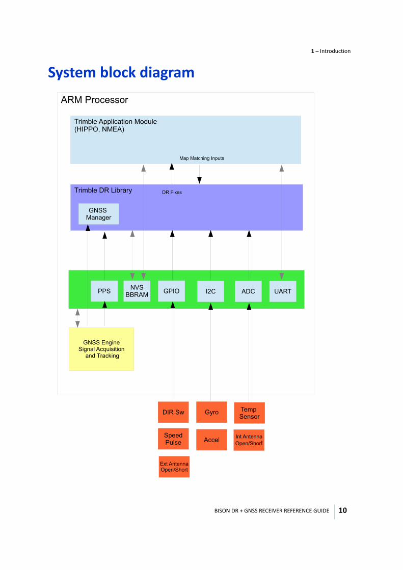
System block diagram
������������ ���������������������
������������� �
!�""��#���"�#� ��$��%�����
���� �&��#
��" !��� �'(�)"
**���( +��
!�""� � #��
�������%%��
����"��%��
���",
"�������%� ����
�-������ ����."/���
! ��
��������
����."/���
� �� ��/��#�����%
��0�-�%
BISON DR + GNSS RECEIVER REFERENCE GUIDE
1 – Introduction
11
General recommendations • The design of the RF transmission line that connects the GNSS antenna to the device is critical to
system performance. If the overall RF system is not implemented correctly, the device performance may be degraded.
• The radio frequency (RF) input on the device is a 50 Ω, unbalanced input. There are ground castellations, pins 2 and 4, on both sides of the RF input castellation on pin 3. This RF input must be connected to the output of an LNA that has a GNSS antenna at its input.
• Connections to either the LNA output must be made using a 50 Ω, unbalanced transmission system. This transmission system may take any form, such as microstrip, coaxial, stripline, or any 50 Ω, characteristic impedance unbalanced, low-loss system. It is important to keep any noise sources with frequencies at or near 1575 MHz and 1602 MHz away from the RF input.
• In the printed circuit board (PCB) layout, Trimble requires that you keep the PCB layer on which the device is mounted clear of solder mask and copper (vias or traces) under the module. This is to ensure mating of the castellations between the device and the board to which it is mounted, and to ensure that there is no interference with any feature beneath the device that will cause it to lift during the re-flow solder process.
• The I2C lines are not made available as loading the line can cause the hardware to lock up.
Carrier boardAn evaluation board is available for the BN1919 receiver module. The evaluation board allows customers to quickly test and evaluate the performance of the module without the hassle of designing their own PCB to mount the module on. This cuts down on customer development time to market and is cost effective.
The electrical connector to the module uses a 24-pin Hirose part and has a cable assembly available for connection to the receiver.
You can order the carrier board as a separate product, the BN3000. For more information, contact your Trimble sales representative.
2
BISON DR + GNSS RECEIVER REFERENCE GUIDE 12
C H A P T E R
Performance Specifications 2
In this chapter:
Global Navigation Satellite System (GNSS)
Dead reckoning (DR)
Electrical
Environmental
This chapter describes the key performance specifications of the Bison module.
Note – For mechanical specifications, see Chapter 6, Mechanical Specifications.
BISON DR + GNSS RECEIVER REFERENCE GUIDE
2 – Performance Specifications
13
Global Navigation Satellite System (GNSS)The Bison module use a single-frequency L1 that can track GPS and GLONASS constellations. However, the solution uses only GPS or GLONASS at any given time.
All performance, accuracy, acquisition and availability requirements assume the following conditions, unless otherwise specified:
• Clear view of the sky • Multipath-free environment• ≥ 5 satellites in view• > 36 CNO signal strengths• Stable temperature (<2 °C change per minute)• < 6 PDOP• Position change < 800 km since last power down.
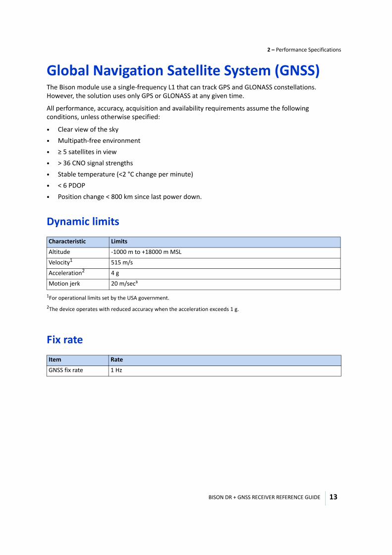
Dynamic limits
Fix rate
Characteristic Limits
Altitude -1000 m to +18000 m MSL
Velocity1
1For operational limits set by the USA government.
515 m/s
Acceleration2
2The device operates with reduced accuracy when the acceleration exceeds 1 g.
4 g
Motion jerk 20 m/sec³
Item Rate
GNSS fix rate 1 Hz
BISON DR + GNSS RECEIVER REFERENCE GUIDE
2 – Performance Specifications
14
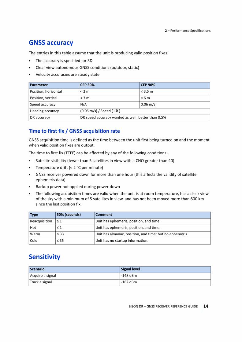
GNSS accuracyThe entries in this table assume that the unit is producing valid position fixes.
• The accuracy is specified for 3D• Clear view autonomous GNSS conditions (outdoor, static) • Velocity accuracies are steady state
Time to first fix / GNSS acquisition rateGNSS acquisition time is defined as the time between the unit first being turned on and the moment when valid position fixes are output.
The time to first fix (TTFF) can be affected by any of the following conditions:
• Satellite visibility (fewer than 5 satellites in view with a CNO greater than 40)• Temperature drift (< 2 °C per minute)• GNSS receiver powered down for more than one hour (this affects the validity of satellite
ephemeris data)• Backup power not applied during power-down• The following acquisition times are valid when the unit is at room temperature, has a clear view
of the sky with a minimum of 5 satellites in view, and has not been moved more than 800 km since the last position fix.
Sensitivity
Parameter CEP 50% CEP 90%
Position, horizontal < 2 m < 3.5 m
Position, vertical < 3 m < 6 m
Speed accuracy N/A 0.06 m/s
Heading accuracy (0.05 m/s) / Speed (1 δ )
DR accuracy DR speed accuracy wanted as well, better than 0.5%
Type 50% (seconds) Comment
Reacquisition ≤ 1 Unit has ephemeris, position, and time.
Hot ≤ 1 Unit has ephemeris, position, and time.
Warm ≤ 33 Unit has almanac, position, and time; but no ephemeris.
Cold ≤ 35 Unit has no startup information.
Scenario Signal level
Acquire a signal -148 dBm
Track a signal -162 dBm
BISON DR + GNSS RECEIVER REFERENCE GUIDE
2 – Performance Specifications
15
Dead reckoning (DR)
Time to first fix - DR
Fix rate
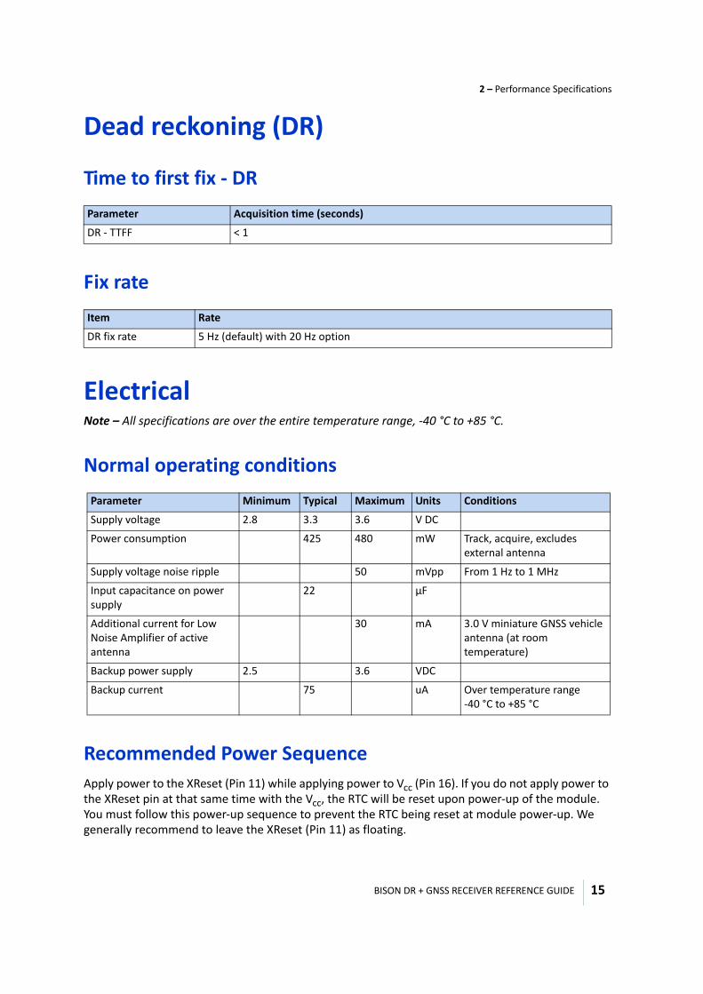
Electrical Note – All specifications are over the entire temperature range, -40 °C to +85 °C.
Normal operating conditions
Recommended Power SequenceApply power to the XReset (Pin 11) while applying power to Vcc (Pin 16). If you do not apply power to the XReset pin at that same time with the Vcc, the RTC will be reset upon power-up of the module. You must follow this power-up sequence to prevent the RTC being reset at module power-up. We generally recommend to leave the XReset (Pin 11) as floating.
Parameter Acquisition time (seconds)
DR - TTFF < 1
Item Rate
DR fix rate 5 Hz (default) with 20 Hz option
Parameter Minimum Typical Maximum Units Conditions
Supply voltage 2.8 3.3 3.6 V DC
Power consumption 425 480 mW Track, acquire, excludes external antenna
Supply voltage noise ripple 50 mVpp From 1 Hz to 1 MHz
Input capacitance on power supply
22 µF
Additional current for Low Noise Amplifier of active antenna
30 mA 3.0 V miniature GNSS vehicle antenna (at room temperature)
Backup power supply 2.5 3.6 VDC
Backup current 75 uA Over temperature range -40 °C to +85 °C
BISON DR + GNSS RECEIVER REFERENCE GUIDE
2 – Performance Specifications
16
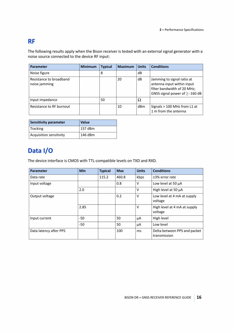
RFThe following results apply when the Bison receiver is tested with an external signal generator with a noise source connected to the device RF input:
Data I/OThe device interface is CMOS with TTL-compatible levels on TXD and RXD.
Parameter Minimum Typical Maximum Units Conditions
Noise figure 8 dB
Resistance to broadband noise jamming
20 dB Jamming to signal ratio at antenna input within input filter bandwidth of 20 MHz; GNSS signal power of ≥ -160 dB
Input impedance 50 ΩResistance to RF burnout 10 dBm Signals > 100 MHz from L1 at
1 m from the antenna
Sensitivity parameter Value
Tracking 157 dBm
Acquisition sensitivity 146 dBm
Parameter Min Typical Max Units Conditions
Data rate 115.2 460.8 kbps ±3% error rate
Input voltage 0.8 V Low level at 50 µA
2.0 V High level at 50 µA
Output voltage 0.2 V Low level at 4 mA at supply voltage
2.85 V High level at 4 mA at supply voltage
Input current -50 50 µA High level
-50 50 µA Low level
Data latency after PPS 100 ms Delta between PPS and packet transmission
BISON DR + GNSS RECEIVER REFERENCE GUIDE
2 – Performance Specifications
17
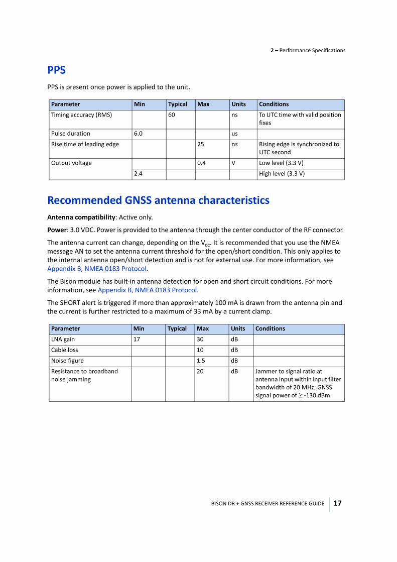
PPSPPS is present once power is applied to the unit.
Recommended GNSS antenna characteristicsAntenna compatibility: Active only.
Power: 3.0 VDC. Power is provided to the antenna through the center conductor of the RF connector.
The antenna current can change, depending on the Vcc. It is recommended that you use the NMEA message AN to set the antenna current threshold for the open/short condition. This only applies to the internal antenna open/short detection and is not for external use. For more information, see Appendix B, NMEA 0183 Protocol.
The Bison module has built-in antenna detection for open and short circuit conditions. For more information, see Appendix B, NMEA 0183 Protocol.
The SHORT alert is triggered if more than approximately 100 mA is drawn from the antenna pin and the current is further restricted to a maximum of 33 mA by a current clamp.
Parameter Min Typical Max Units Conditions
Timing accuracy (RMS) 60 ns To UTC time with valid position fixes
Pulse duration 6.0 us
Rise time of leading edge 25 ns Rising edge is synchronized to UTC second
Output voltage 0.4 V Low level (3.3 V)
2.4 High level (3.3 V)
Parameter Min Typical Max Units Conditions
LNA gain 17 30 dB
Cable loss 10 dB
Noise figure 1.5 dB
Resistance to broadband noise jamming
20 dB Jammer to signal ratio at antenna input within input filter bandwidth of 20 MHz; GNSS signal power of ≥ -130 dBm
BISON DR + GNSS RECEIVER REFERENCE GUIDE
2 – Performance Specifications
18
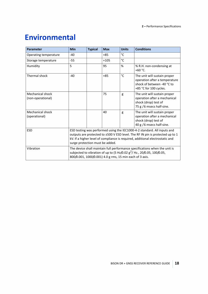
Environmental Parameter Min Typical Max Units Conditions
Operating temperature -40 +85 °C
Storage temperature -55 +105 °C
Humidity 5 95 % % R.H. non-condensing at +60 °C.
Thermal shock -40 +85 °C The unit will sustain proper operation after a temperature shock of between -40 °C to +85 °C for 100 cycles.
Mechanical shock (non-operational)
75 g The unit will sustain proper operation after a mechanical shock (drop) test of 75 g / 6 msecs half-sine.
Mechanical shock (operational)
40 g The unit will sustain proper operation after a mechanical shock (drop) test of 40 g / 6 msecs half-sine.
ESD ESD testing was performed using the IEC1000-4-2 standard. All inputs and outputs are protected to ±500 V ESD level. The RF IN pin is protected up to 1 kV. If a higher level of compliance is required, additional electrostatic and surge protection must be added.
Vibration The device shall maintain full performance specifications when the unit is subjected to vibration of up to (5 Hz/0.02 g2/ Hz., 20/0.05, 100/0.05, 800/0.001, 1000/0.001) 4.0 g rms, 15 min each of 3 axis.
3
BISON DR + GNSS RECEIVER REFERENCE GUIDE 19
C H A P T E R
Interface Characteristics 3
In this chapter:
Pin-out assignments
Detailed pin description
This chapter describes the key mechanical specifications of the Bison module.
BISON DR + GNSS RECEIVER REFERENCE GUIDE
3 – Interface Characteristics
20
Pin-out assignments
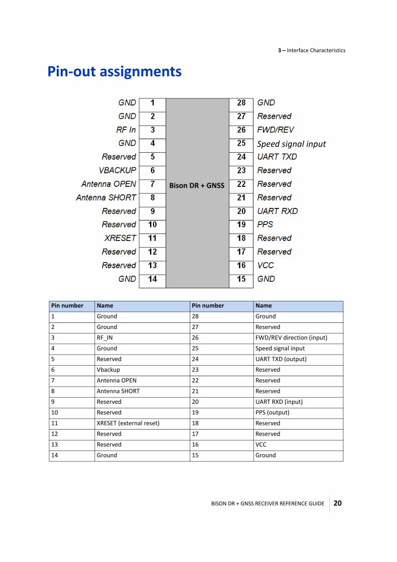
Pin number Name Pin number Name
1 Ground 28 Ground
2 Ground 27 Reserved
3 RF_IN 26 FWD/REV direction (input)
4 Ground 25 Speed signal input
5 Reserved 24 UART TXD (output)
6 Vbackup 23 Reserved
7 Antenna OPEN 22 Reserved
8 Antenna SHORT 21 Reserved
9 Reserved 20 UART RXD (input)
10 Reserved 19 PPS (output)
11 XRESET (external reset) 18 Reserved
12 Reserved 17 Reserved
13 Reserved 16 VCC
14 Ground 15 Ground
Bison DR + GNSS
Speed signal input
BISON DR + GNSS RECEIVER REFERENCE GUIDE
3 – Interface Characteristics
21
Detailed pin description
RFINThe RF input pin is the 50 Ω unbalanced GNSS RF input, and can be used with active antennas.
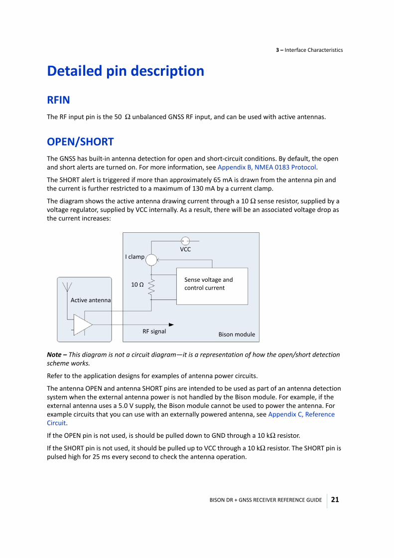
OPEN/SHORTThe GNSS has built-in antenna detection for open and short-circuit conditions. By default, the open and short alerts are turned on. For more information, see Appendix B, NMEA 0183 Protocol.
The SHORT alert is triggered if more than approximately 65 mA is drawn from the antenna pin and the current is further restricted to a maximum of 130 mA by a current clamp.
The diagram shows the active antenna drawing current through a 10 Ω sense resistor, supplied by a voltage regulator, supplied by VCC internally. As a result, there will be an associated voltage drop as the current increases:
Note – This diagram is not a circuit diagram—it is a representation of how the open/short detection scheme works.
Refer to the application designs for examples of antenna power circuits.
The antenna OPEN and antenna SHORT pins are intended to be used as part of an antenna detection system when the external antenna power is not handled by the Bison module. For example, if the external antenna uses a 5.0 V supply, the Bison module cannot be used to power the antenna. For example circuits that you can use with an externally powered antenna, see Appendix C, Reference Circuit.
If the OPEN pin is not used, is should be pulled down to GND through a 10 kΩ resistor.
If the SHORT pin is not used, it should be pulled up to VCC through a 10 kΩ resistor. The SHORT pin is pulsed high for 25 ms every second to check the antenna operation.
Bison module
Sense voltage and control current
VCCI clamp
10 Ω
Active antenna
RF signal
BISON DR + GNSS RECEIVER REFERENCE GUIDE
3 – Interface Characteristics
22
XRESET Use this logic-level, active low input to issue a reset to the module. It can be connected to external logic or to a processor to issue a reset instruction. To reset the module, drive this pin to logic level “0” or “Low” for at least 100 microseconds, and then either release this signal or drive it back high. This pin has an internal 4.7 kΩ pull-up resister; if this pin is not used, leave it disconnected.
VCC This is the primary voltage supply pin for the module.
RXDThis logic level input is the serial port receive line (data input to the module). Leave disconnected if not used.
TXDThis logic level output is the serial port transmit line (data output from the module). Leave disconnected if not used.
Speed signal input sensor2.8 V LVTTL, 3.3 V to 5 V tolerable. Maximum speed pulse frequency is 3 kHz.
FWD/REV direction switch2.8 V TTL, 3.3 V to 5 V tolerable. The Bison receiver can work with both High (FWD) and Low (FWD) conventions. The Bison module will determine the sign of the direction switch automatically when the device is first used.
RESERVEDThere are several reserved pins. Do not connect these pins.
Note – Do not place solder mask, copper traces, vias, or other conductive elements under the module when designing the Bison module into your system.
4
BISON DR + GNSS RECEIVER REFERENCE GUIDE 23
C H A P T E R
Orientation and Calibration 4
In this chapter:
General Bison module coordinate system
Dead-reckoning (DR) calibration
The Bison module must know its mounting orientation for proper operation. If the mounting orientation is known, users can program the orientation angles directly into the module. The receiver will immediately start in DR mode.
BISON DR + GNSS RECEIVER REFERENCE GUIDE
4 – Orientation and Calibration
24
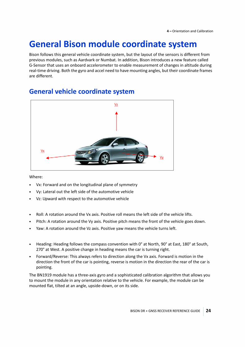
General Bison module coordinate systemBison follows this general vehicle coordinate system, but the layout of the sensors is different from previous modules, such as Aardvark or Numbat. In addition, Bison introduces a new feature called G-Sensor that uses an onboard accelerometer to enable measurement of changes in altitude during real-time driving. Both the gyro and accel need to have mounting angles, but their coordinate frames are different.
General vehicle coordinate system
Where:
• Vx: Forward and on the longitudinal plane of symmetry• Vy: Lateral out the left side of the automotive vehicle• Vz: Upward with respect to the automotive vehicle
• Roll: A rotation around the Vx axis. Positive roll means the left side of the vehicle lifts.• Pitch: A rotation around the Vy axis. Positive pitch means the front of the vehicle goes down.• Yaw: A rotation around the Vz axis. Positive yaw means the vehicle turns left.
• Heading: Heading follows the compass convention with 0° at North, 90° at East, 180° at South, 270° at West. A positive change in heading means the car is turning right.
• Forward/Reverse: This always refers to direction along the Vx axis. Forward is motion in the direction the front of the car is pointing, reverse is motion in the direction the rear of the car is pointing.
The BN1919 module has a three-axis gyro and a sophisticated calibration algorithm that allows you to mount the module in any orientation relative to the vehicle. For example, the module can be mounted flat, tilted at an angle, upside-down, or on its side.
BISON DR + GNSS RECEIVER REFERENCE GUIDE
4 – Orientation and Calibration
25
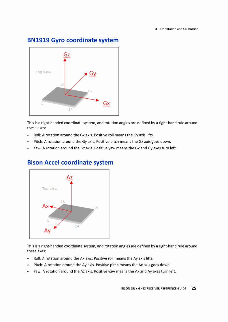
BN1919 Gyro coordinate system
This is a right-handed coordinate system, and rotation angles are defined by a right-hand rule around these axes:
• Roll: A rotation around the Gx axis. Positive roll means the Gy axis lifts.• Pitch: A rotation around the Gy axis. Positive pitch means the Gx axis goes down.• Yaw: A rotation around the Gz axis. Positive yaw means the Gx and Gy axes turn left.
Bison Accel coordinate system
This is a right-handed coordinate system, and rotation angles are defined by a right-hand rule around these axes:
• Roll: A rotation around the Ax axis. Positive roll means the Ay axis lifts.• Pitch: A rotation around the Ay axis. Positive pitch means the Ax axis goes down.• Yaw: A rotation around the Az axis. Positive yaw means the Ax and Ay axes turn left.
BISON DR + GNSS RECEIVER REFERENCE GUIDE
4 – Orientation and Calibration
26
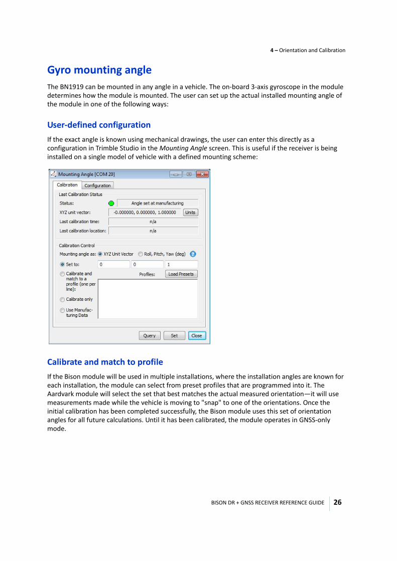
Gyro mounting angleThe BN1919 can be mounted in any angle in a vehicle. The on-board 3-axis gyroscope in the module determines how the module is mounted. The user can set up the actual installed mounting angle of the module in one of the following ways:
User-defined configurationIf the exact angle is known using mechanical drawings, the user can enter this directly as a configuration in Trimble Studio in the Mounting Angle screen. This is useful if the receiver is being installed on a single model of vehicle with a defined mounting scheme:
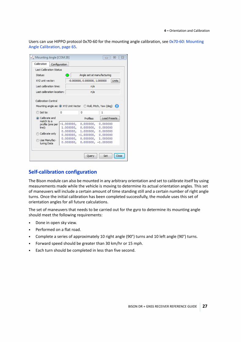
Calibrate and match to profileIf the Bison module will be used in multiple installations, where the installation angles are known for each installation, the module can select from preset profiles that are programmed into it. The Aardvark module will select the set that best matches the actual measured orientation—it will use measurements made while the vehicle is moving to "snap" to one of the orientations. Once the initial calibration has been completed successfully, the Bison module uses this set of orientation angles for all future calculations. Until it has been calibrated, the module operates in GNSS-only mode.
BISON DR + GNSS RECEIVER REFERENCE GUIDE
4 – Orientation and Calibration
27
Users can use HIPPO protocol 0x70-60 for the mounting angle calibration, see 0x70-60: Mounting Angle Calibration, page 65.
Self-calibration configurationThe Bison module can also be mounted in any arbitrary orientation and set to calibrate itself by using measurements made while the vehicle is moving to determine its actual orientation angles. This set of maneuvers will include a certain amount of time standing still and a certain number of right angle turns. Once the initial calibration has been completed successfully, the module uses this set of orientation angles for all future calculations.
The set of maneuvers that needs to be carried out for the gyro to determine its mounting angle should meet the following requirements:
• Done in open sky view.• Performed on a flat road.• Complete a series of approximately 10 right angle (90°) turns and 10 left angle (90°) turns. • Forward speed should be greater than 30 km/hr or 15 mph.• Each turn should be completed in less than five second.
BISON DR + GNSS RECEIVER REFERENCE GUIDE
4 – Orientation and Calibration
28
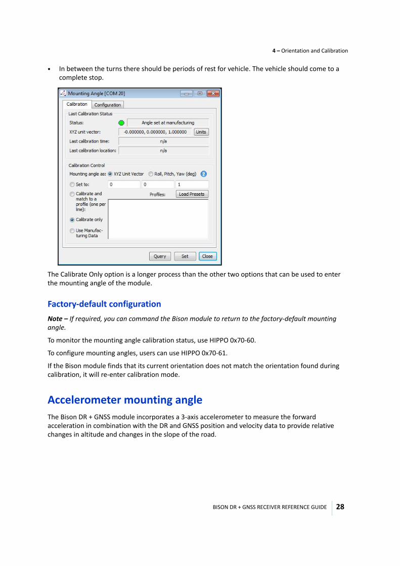
• In between the turns there should be periods of rest for vehicle. The vehicle should come to a complete stop.
The Calibrate Only option is a longer process than the other two options that can be used to enter the mounting angle of the module.
Factory-default configurationNote – If required, you can command the Bison module to return to the factory-default mounting angle.
To monitor the mounting angle calibration status, use HIPPO 0x70-60.
To configure mounting angles, users can use HIPPO 0x70-61.
If the Bison module finds that its current orientation does not match the orientation found during calibration, it will re-enter calibration mode.
Accelerometer mounting angleThe Bison DR + GNSS module incorporates a 3-axis accelerometer to measure the forward acceleration in combination with the DR and GNSS position and velocity data to provide relative changes in altitude and changes in the slope of the road.
BISON DR + GNSS RECEIVER REFERENCE GUIDE
4 – Orientation and Calibration
29
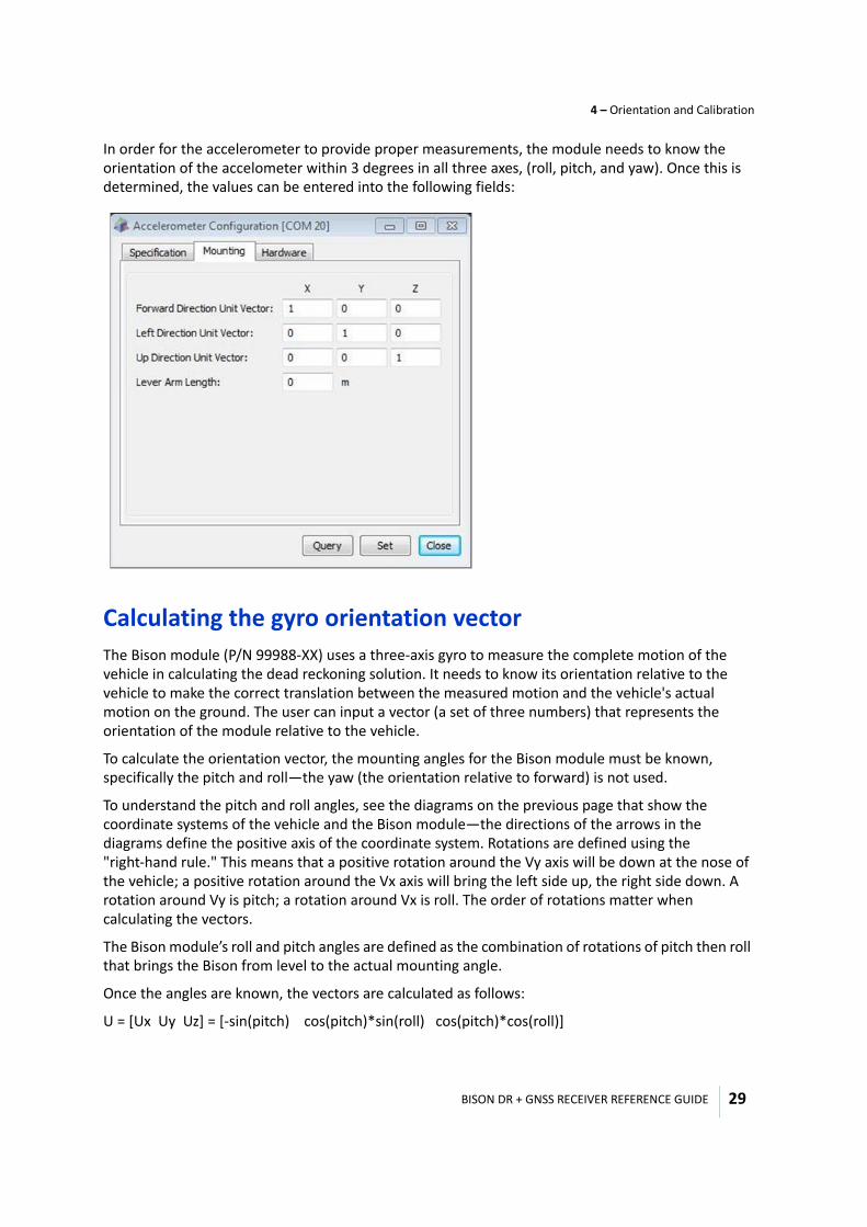
In order for the accelerometer to provide proper measurements, the module needs to know the orientation of the accelometer within 3 degrees in all three axes, (roll, pitch, and yaw). Once this is determined, the values can be entered into the following fields:
Calculating the gyro orientation vectorThe Bison module (P/N 99988-XX) uses a three-axis gyro to measure the complete motion of the vehicle in calculating the dead reckoning solution. It needs to know its orientation relative to the vehicle to make the correct translation between the measured motion and the vehicle's actual motion on the ground. The user can input a vector (a set of three numbers) that represents the orientation of the module relative to the vehicle.
To calculate the orientation vector, the mounting angles for the Bison module must be known, specifically the pitch and roll—the yaw (the orientation relative to forward) is not used.
To understand the pitch and roll angles, see the diagrams on the previous page that show the coordinate systems of the vehicle and the Bison module—the directions of the arrows in the diagrams define the positive axis of the coordinate system. Rotations are defined using the "right-hand rule." This means that a positive rotation around the Vy axis will be down at the nose of the vehicle; a positive rotation around the Vx axis will bring the left side up, the right side down. A rotation around Vy is pitch; a rotation around Vx is roll. The order of rotations matter when calculating the vectors.
The Bison module’s roll and pitch angles are defined as the combination of rotations of pitch then roll that brings the Bison from level to the actual mounting angle.
Once the angles are known, the vectors are calculated as follows:
U = [Ux Uy Uz] = [-sin(pitch) cos(pitch)*sin(roll) cos(pitch)*cos(roll)]
BISON DR + GNSS RECEIVER REFERENCE GUIDE
4 – Orientation and Calibration
30
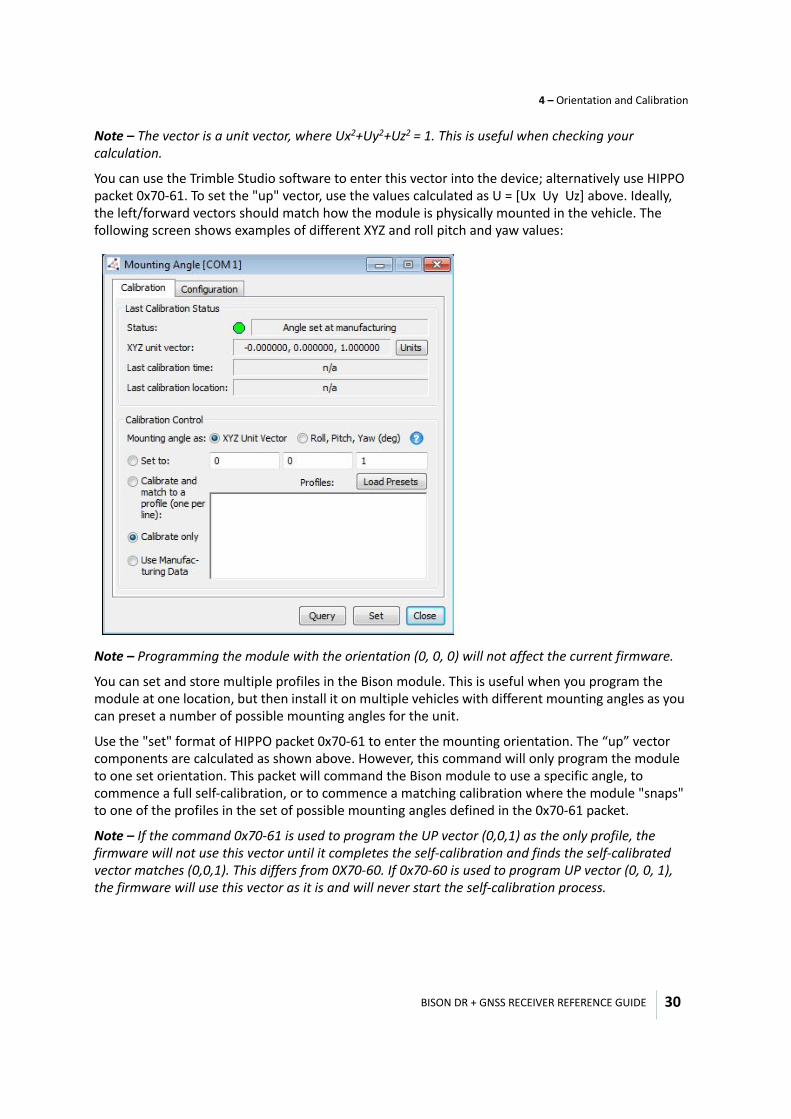
Note – The vector is a unit vector, where Ux2+Uy2+Uz2 = 1. This is useful when checking your calculation.
You can use the Trimble Studio software to enter this vector into the device; alternatively use HIPPO packet 0x70-61. To set the "up" vector, use the values calculated as U = [Ux Uy Uz] above. Ideally, the left/forward vectors should match how the module is physically mounted in the vehicle. The following screen shows examples of different XYZ and roll pitch and yaw values:
Note – Programming the module with the orientation (0, 0, 0) will not affect the current firmware.
You can set and store multiple profiles in the Bison module. This is useful when you program the module at one location, but then install it on multiple vehicles with different mounting angles as you can preset a number of possible mounting angles for the unit.
Use the "set" format of HIPPO packet 0x70-61 to enter the mounting orientation. The “up” vector components are calculated as shown above. However, this command will only program the module to one set orientation. This packet will command the Bison module to use a specific angle, to commence a full self-calibration, or to commence a matching calibration where the module "snaps" to one of the profiles in the set of possible mounting angles defined in the 0x70-61 packet.
Note – If the command 0x70-61 is used to program the UP vector (0,0,1) as the only profile, the firmware will not use this vector until it completes the self-calibration and finds the self-calibrated vector matches (0,0,1). This differs from 0X70-60. If 0x70-60 is used to program UP vector (0, 0, 1), the firmware will use this vector as it is and will never start the self-calibration process.
BISON DR + GNSS RECEIVER REFERENCE GUIDE
4 – Orientation and Calibration
31
Dead-reckoning (DR) calibrationNote – Users can only proceed with the DR calibration once the mounting angle of the module has been determined. If they do not do this, the DR performance will not meet specification.
Purpose of dead-reckoning calibrationUsers must calibrate the Bison DR + GNSS receiver after installation to ensure an accurate output from the receiver. The calibration will measure some of the characteristics that are specific to the vehicle installation, and is done automatically when the unit is first installed.
Before the module is calibrated, it will provide a GNSS position once. After calibration, the receiver will operate in DR+GNSS position. It shows a status flag to inform customers of the mode in which the unit is operating.
To calibrate the receiver, you must drive a set of maneuvers that will give the receiver visibility into the following parameters:
• Distance per pulse (DPP)—this calibrates the odometer output to relate output pulses to meters traveled. It is a combination of the actual vehicle Speed signal output characteristics and the tire size and pressure.
• Direction switch—the receiver determines whether the output of the direction switch is high or low when traveling forward.
• Gyro offset (Zero Rate Output [ZRO])—this is the output of the on-board gyro when the vehicle is not moving.
• Gyro scale factor (GSF)—this is the relationship between the output of the gyro and the actual turning rate.
General calibration requirementsDR calibration involves the parameters DPP, direction switch, ZRO, and GSF—they are largely calibrated in parallel.
To do this, you can drive a set of 10 or more 90° turns (both right hand and left hand) with a forward speed greater than 30 km/hr (18 mph) and certain speed before the turns. Separate the turns with the some intervals of the vehicle at a standstill. For example, if the vehicle makes four right hand turns, stop for 5 seconds before starting again. The calibration drive must be done on a flat road and in open sky conditions that provides good GNSS visibility.
During this time:
• DPP calibrates at any time that there is a good GNSS track. • The direction turn switch calibrates during the first motion.• ZRO is calibrated at any time that the vehicle is not moving.• GSF is calibrated during turns.You only need to complete the initial calibration once. After the initial calibration, the receiver will continually update the calibration whenever it has appropriate data with good GNSS tracking.

5
BISON DR + GNSS RECEIVER REFERENCE GUIDE 32
C H A P T E R
Software 5
In this chapter:
Port configuration
Tools
Software
Interfaces
Communication protocols
This chapter describes the software used with the Bison receiver.
BISON DR + GNSS RECEIVER REFERENCE GUIDE
5 – Software
33
Port configuration
Tools
Software
Features
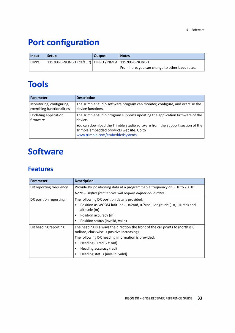
Input Setup Output Notes
HIPPO 115200-8-NONE-1 (default) HIPPO / NMEA 115200-8-NONE-1From here, you can change to other baud rates.
Parameter Description
Monitoring, configuring, exercising functionalities
The Trimble Studio software program can monitor, configure, and exercise the device functions.
Updating application firmware
The Trimble Studio program supports updating the application firmware of the device.You can download the Trimble Studio software from the Support section of the Trimble embedded products website. Go to www.trimble.com/embeddedsystems
Parameter Description
DR reporting frequency Provide DR positioning data at a programmable frequency of 5 Hz to 20 Hz.Note – Higher frequencies will require higher baud rates.
DR position reporting The following DR position data is provided:• Position as WGS84 latitude (- π/2rad, π/2rad), longitude (- π, +π rad) and
altitude (m)• Position accuracy (m)• Position status (invalid, valid)
DR heading reporting The heading is always the direction the front of the car points to (north is 0 radians; clockwise is positive increasing).The following DR heading information is provided:• Heading (0 rad, 2π rad)• Heading accuracy (rad) • Heading status (invalid, valid)
BISON DR + GNSS RECEIVER REFERENCE GUIDE
5 – Software
34
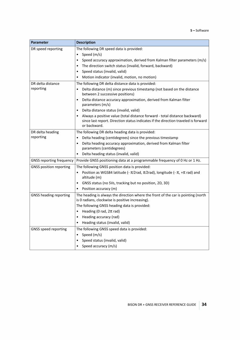
DR speed reporting The following DR speed data is provided:• Speed (m/s)• Speed accuracy approximation, derived from Kalman filter parameters (m/s)• The direction switch status (invalid, forward, backward)• Speed status (invalid, valid)• Motion indicator (invalid, motion, no motion)
DR delta distance reporting
The following DR delta distance data is provided:• Delta distance (m) since previous timestamp (not based on the distance
between 2 successive positions)• Delta distance accuracy approximation, derived from Kalman filter
parameters (m/s)• Delta distance status (invalid, valid)• Always a positive value (total distance forward - total distance backward)
since last report. Direction status indicates if the direction traveled is forward or backward.
DR delta heading reporting
The following DR delta heading data is provided:• Delta heading (centidegrees) since the previous timestamp• Delta heading accuracy approximation, derived from Kalman filter
parameters (centidegrees)• Delta heading status (invalid, valid)
GNSS reporting frequency Provide GNSS positioning data at a programmable frequency of 0 Hz or 1 Hz.
GNSS position reporting The following GNSS position data is provided:• Position as WGS84 latitude (- π/2rad, π/2rad), longitude (- π, +π rad) and
altitude (m)• GNSS status (no SVs, tracking but no position, 2D, 3D)• Position accuracy (m)
GNSS heading reporting The heading is always the direction where the front of the car is pointing (north is 0 radians, clockwise is positive increasing). The following GNSS heading data is provided:• Heading (0 rad, 2π rad)• Heading accuracy (rad) • Heading status (invalid, valid)
GNSS speed reporting The following GNSS speed data is provided:• Speed (m/s)• Speed status (invalid, valid)• Speed accuracy (m/s)
Parameter Description
BISON DR + GNSS RECEIVER REFERENCE GUIDE
5 – Software
35
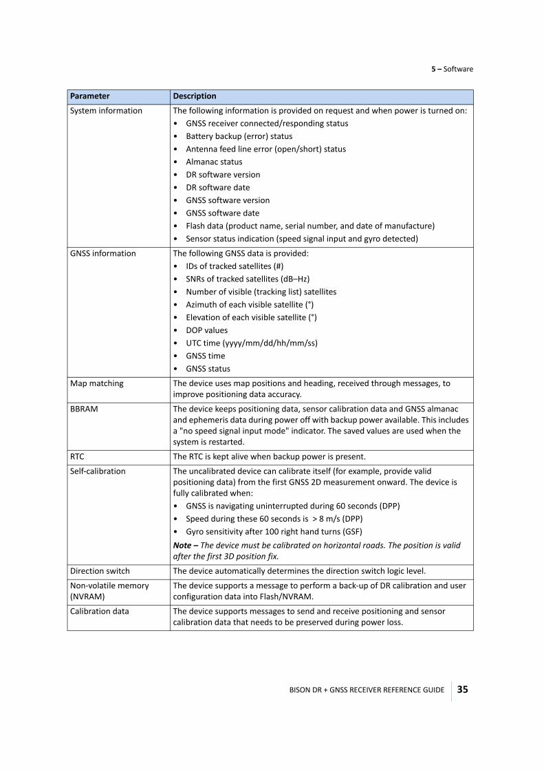
System information The following information is provided on request and when power is turned on:• GNSS receiver connected/responding status• Battery backup (error) status• Antenna feed line error (open/short) status• Almanac status• DR software version• DR software date• GNSS software version• GNSS software date• Flash data (product name, serial number, and date of manufacture)• Sensor status indication (speed signal input and gyro detected)
GNSS information The following GNSS data is provided:• IDs of tracked satellites (#)• SNRs of tracked satellites (dB–Hz)• Number of visible (tracking list) satellites• Azimuth of each visible satellite (°)• Elevation of each visible satellite (°)• DOP values• UTC time (yyyy/mm/dd/hh/mm/ss) • GNSS time • GNSS status
Map matching The device uses map positions and heading, received through messages, to improve positioning data accuracy.
BBRAM The device keeps positioning data, sensor calibration data and GNSS almanac and ephemeris data during power off with backup power available. This includes a "no speed signal input mode" indicator. The saved values are used when the system is restarted.
RTC The RTC is kept alive when backup power is present.
Self-calibration The uncalibrated device can calibrate itself (for example, provide valid positioning data) from the first GNSS 2D measurement onward. The device is fully calibrated when:• GNSS is navigating uninterrupted during 60 seconds (DPP)• Speed during these 60 seconds is > 8 m/s (DPP)• Gyro sensitivity after 100 right hand turns (GSF)Note – The device must be calibrated on horizontal roads. The position is valid after the first 3D position fix.
Direction switch The device automatically determines the direction switch logic level.
Non-volatile memory (NVRAM)
The device supports a message to perform a back-up of DR calibration and user configuration data into Flash/NVRAM.
Calibration data The device supports messages to send and receive positioning and sensor calibration data that needs to be preserved during power loss.
Parameter Description
BISON DR + GNSS RECEIVER REFERENCE GUIDE
5 – Software
36
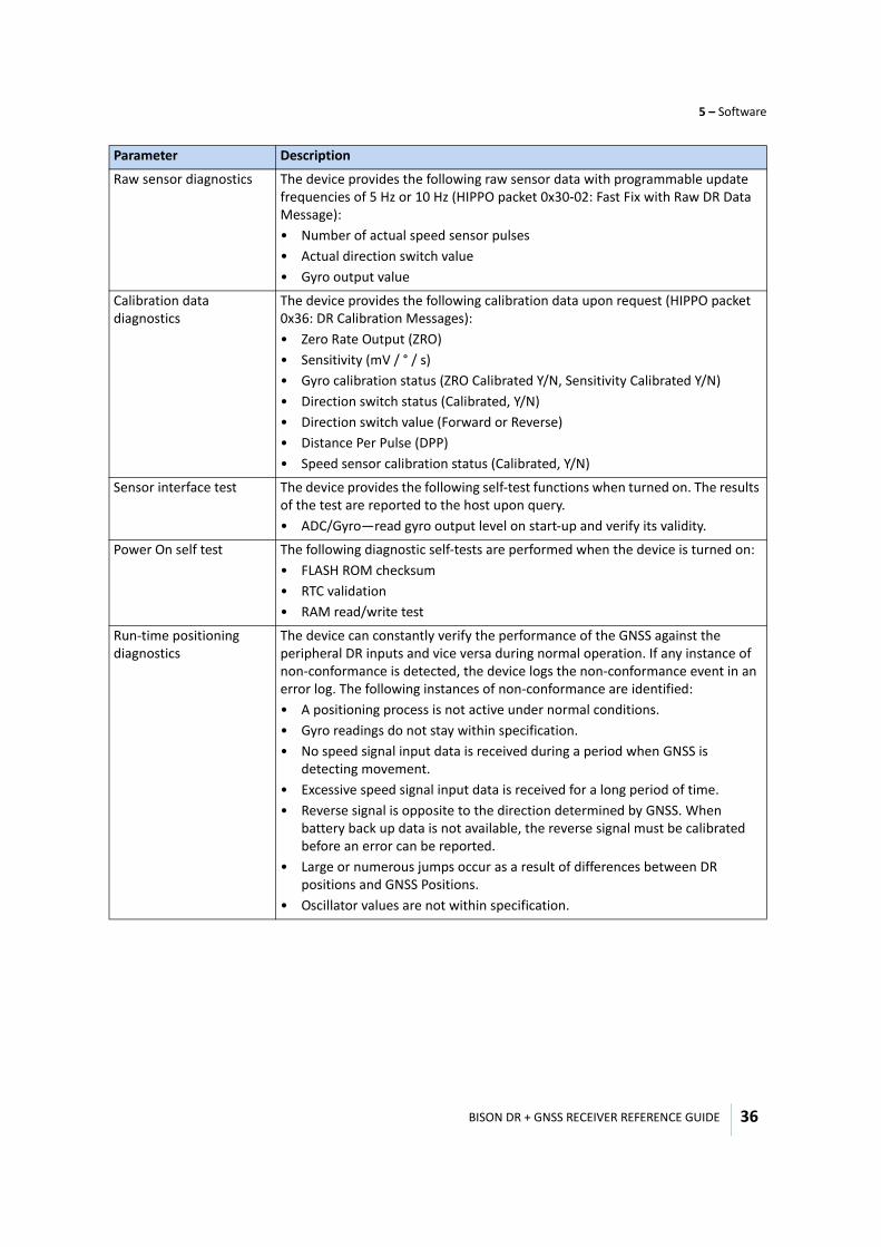
Raw sensor diagnostics The device provides the following raw sensor data with programmable update frequencies of 5 Hz or 10 Hz (HIPPO packet 0x30-02: Fast Fix with Raw DR Data Message):• Number of actual speed sensor pulses• Actual direction switch value• Gyro output value
Calibration data diagnostics
The device provides the following calibration data upon request (HIPPO packet 0x36: DR Calibration Messages):• Zero Rate Output (ZRO)• Sensitivity (mV / ° / s)• Gyro calibration status (ZRO Calibrated Y/N, Sensitivity Calibrated Y/N)• Direction switch status (Calibrated, Y/N)• Direction switch value (Forward or Reverse)• Distance Per Pulse (DPP)• Speed sensor calibration status (Calibrated, Y/N)
Sensor interface test The device provides the following self-test functions when turned on. The results of the test are reported to the host upon query.• ADC/Gyro—read gyro output level on start-up and verify its validity.
Power On self test The following diagnostic self-tests are performed when the device is turned on:• FLASH ROM checksum • RTC validation• RAM read/write test
Run-time positioning diagnostics
The device can constantly verify the performance of the GNSS against the peripheral DR inputs and vice versa during normal operation. If any instance of non-conformance is detected, the device logs the non-conformance event in an error log. The following instances of non-conformance are identified: • A positioning process is not active under normal conditions.• Gyro readings do not stay within specification.• No speed signal input data is received during a period when GNSS is
detecting movement.• Excessive speed signal input data is received for a long period of time.• Reverse signal is opposite to the direction determined by GNSS. When
battery back up data is not available, the reverse signal must be calibrated before an error can be reported.
• Large or numerous jumps occur as a result of differences between DR positions and GNSS Positions.
• Oscillator values are not within specification.
Parameter Description
BISON DR + GNSS RECEIVER REFERENCE GUIDE
5 – Software
37
Performance requirements
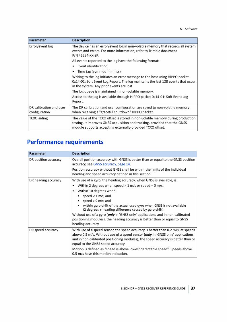
Error/event log The device has an error/event log in non-volatile memory that records all system events and errors. For more information, refer to Trimble document P/N 45294-XX-SP. All events reported to the log have the following format:• Event identification• Time tag (yymmddhhmmss)Writing to the log initiates an error message to the host using HIPPO packet 0x14-01: Soft Event Log Report. The log maintains the last 128 events that occur in the system. Any prior events are lost.The log queue is maintained in non-volatile memory. Access to the log is available through HIPPO packet 0x14-01: Soft Event Log Report.
DR calibration and user configuration
The DR calibration and user configuration are saved to non-volatile memory when receiving a "graceful shutdown" HIPPO packet.
TCXO aiding The value of the TCXO offset is stored in non-volatile memory during production testing. It improves GNSS acquisition and tracking, provided that the GNSS module supports accepting externally-provided TCXO offset.
Parameter Description
DR position accuracy Overall position accuracy with GNSS is better than or equal to the GNSS position accuracy, see GNSS accuracy, page 14.Position accuracy without GNSS shall be within the limits of the individual heading and speed accuracy defined in this section.
DR heading accuracy With use of a gyro, the heading accuracy, when GNSS is available, is:• Within 2 degrees when speed > 1 m/s or speed = 0 m/s.• Within 10 degrees when:
• speed < 1 m/s; and
• speed ≠ 0 m/s; and• within gyro-drift of the actual used gyro when GNSS is not available
(2 degrees + heading difference caused by gyro-drift).
Without use of a gyro (only in 'GNSS only' applications and in non-calibrated positioning modules), the heading accuracy is better than or equal to GNSS heading accuracy.
DR speed accuracy With use of a speed sensor, the speed accuracy is better than 0.2 m/s. at speeds above 0.5 m/s. Without use of a speed sensor (only in 'GNSS only' applications and in non-calibrated positioning modules), the speed accuracy is better than or equal to the GNSS speed accuracy. Motion is defined as "speed is above lowest detectable speed". Speeds above 0.5 m/s have this motion indication.
Parameter Description
BISON DR + GNSS RECEIVER REFERENCE GUIDE
5 – Software
38
Timing or latency requirements
Upgrade requirements
Interfaces
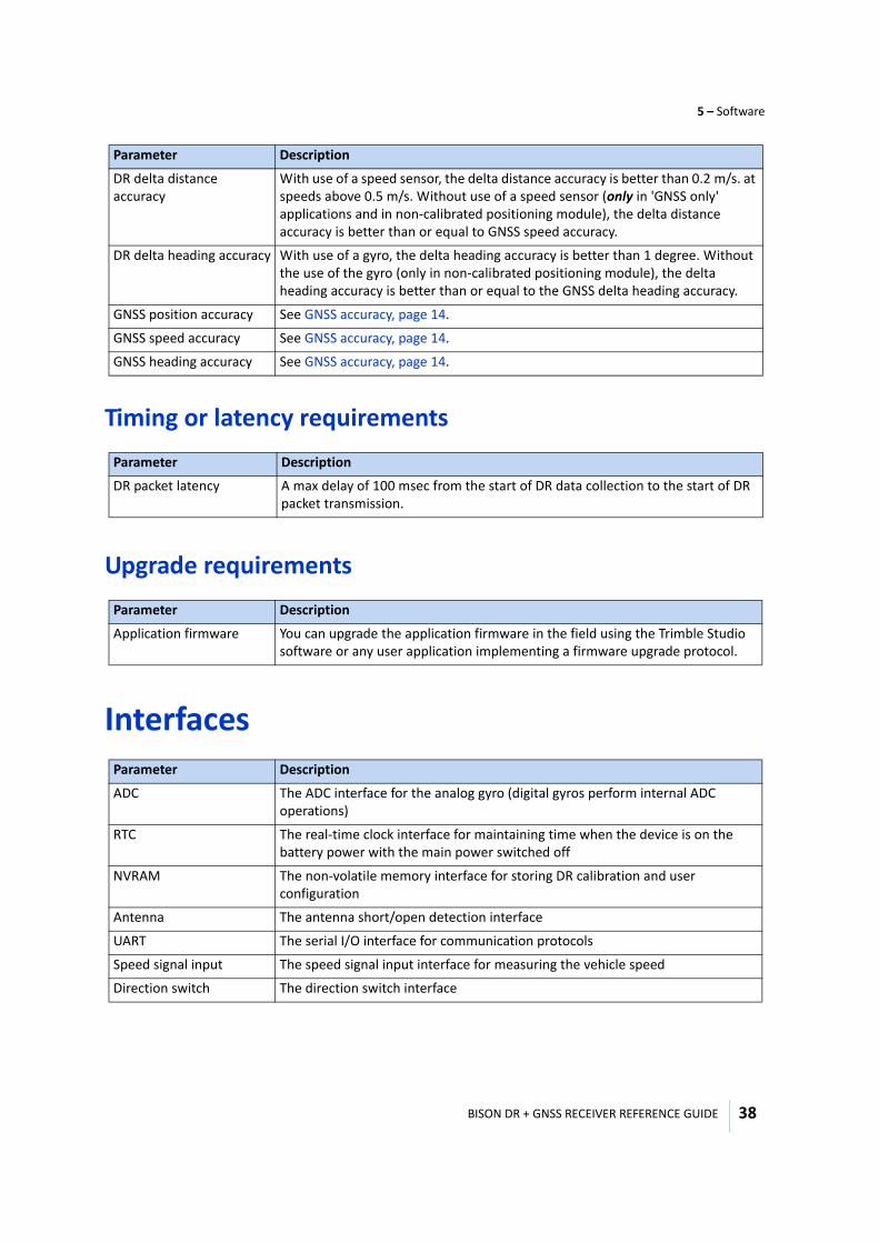
DR delta distance accuracy
With use of a speed sensor, the delta distance accuracy is better than 0.2 m/s. at speeds above 0.5 m/s. Without use of a speed sensor (only in 'GNSS only' applications and in non-calibrated positioning module), the delta distance accuracy is better than or equal to GNSS speed accuracy.
DR delta heading accuracy With use of a gyro, the delta heading accuracy is better than 1 degree. Without the use of the gyro (only in non-calibrated positioning module), the delta heading accuracy is better than or equal to the GNSS delta heading accuracy.
GNSS position accuracy See GNSS accuracy, page 14.
GNSS speed accuracy See GNSS accuracy, page 14.
GNSS heading accuracy See GNSS accuracy, page 14.
Parameter Description
DR packet latency A max delay of 100 msec from the start of DR data collection to the start of DR packet transmission.
Parameter Description
Application firmware You can upgrade the application firmware in the field using the Trimble Studio software or any user application implementing a firmware upgrade protocol.
Parameter Description
ADC The ADC interface for the analog gyro (digital gyros perform internal ADC operations)
RTC The real-time clock interface for maintaining time when the device is on the battery power with the main power switched off
NVRAM The non-volatile memory interface for storing DR calibration and user configuration
Antenna The antenna short/open detection interface
UART The serial I/O interface for communication protocols
Speed signal input The speed signal input interface for measuring the vehicle speed
Direction switch The direction switch interface
Parameter Description
BISON DR + GNSS RECEIVER REFERENCE GUIDE
5 – Software
39
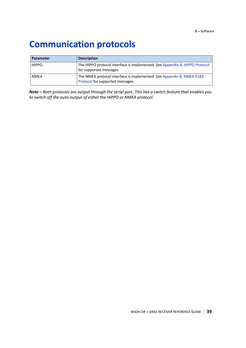
Communication protocols
Note – Both protocols are output through the serial port. This has a switch feature that enables you to switch off the auto-output of either the HIPPO or NMEA protocol.
Parameter Description
HIPPO The HIPPO protocol interface is implemented. See Appendix A, HIPPO Protocol for supported messages.
NMEA The NMEA protocol interface is implemented. See Appendix B, NMEA 0183 Protocol for supported messages.

6
BISON DR + GNSS RECEIVER REFERENCE GUIDE 40
C H A P T E R
Mechanical Specifications 6
In this chapter:
Form factor
Mechanical drawing
Layout
This chapter describes the key mechanical specifications of the Bison module.
BISON DR + GNSS RECEIVER REFERENCE GUIDE
6 – Mechanical Specifications
41
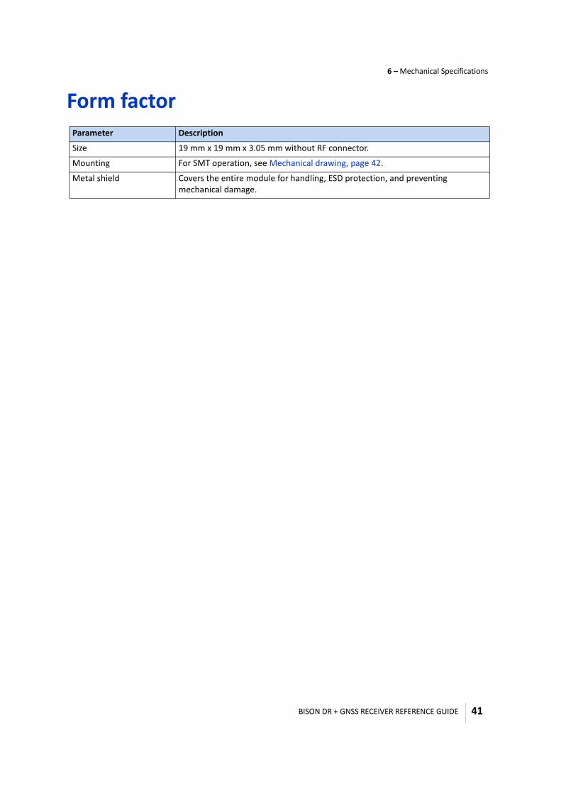
Form factor Parameter Description
Size 19 mm x 19 mm x 3.05 mm without RF connector.
Mounting For SMT operation, see Mechanical drawing, page 42.
Metal shield Covers the entire module for handling, ESD protection, and preventing mechanical damage.
BISON DR + GNSS RECEIVER REFERENCE GUIDE
6 – Mechanical Specifications
42
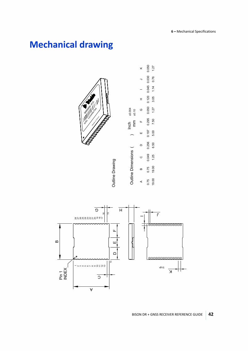
Mechanical drawingB
A
1 2 3 4 5 6 7 8 9 10
11
12
13
14
24
15
23
22
21
20
19
18
17
16
27
26
25
28
IND
EX
C
DE
F
Ou
tlin
e D
ime
nsio
ns
(
)
Inch
mm
Ou
tlin
e D
raw
ing
A
0.7
5
19
.00
B
19
.00
0.7
50
.04
9
1.2
5
CD
6.5
0
0.2
56
E
0.1
97
5.0
0
±0.0
04
±0.1
0
0.2
95
F
7.5
0
GG
0.0
50
1.2
7
H
3.0
5
0.1
20
H
J
0.0
45
1.1
4
II
0.0
30
0.7
6
J
K
0.0
50
1.2
7
K
TYP
Pin
1
BISON DR + GNSS RECEIVER REFERENCE GUIDE
6 – Mechanical Specifications
43
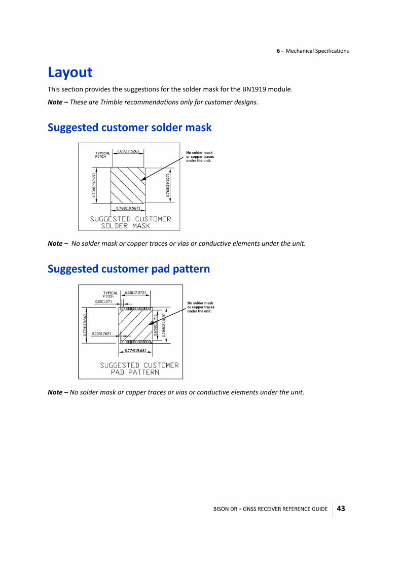
LayoutThis section provides the suggestions for the solder mask for the BN1919 module.
Note – These are Trimble recommendations only for customer designs.
Suggested customer solder mask
Note – No solder mask or copper traces or vias or conductive elements under the unit.
Suggested customer pad pattern
Note – No solder mask or copper traces or vias or conductive elements under the unit.
BISON DR + GNSS RECEIVER REFERENCE GUIDE
6 – Mechanical Specifications
44
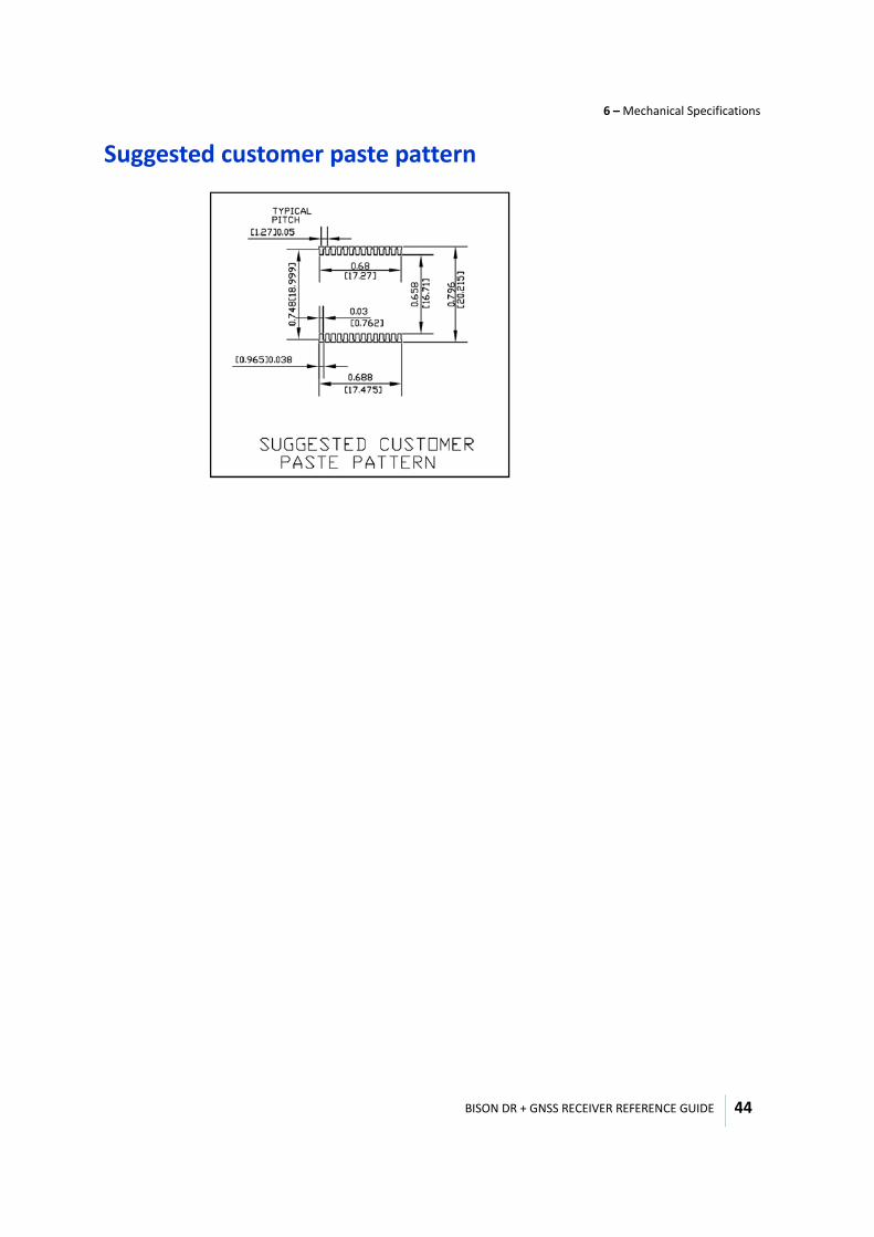
Suggested customer paste pattern

7
BISON DR + GNSS RECEIVER REFERENCE GUIDE 45
C H A P T E R
Storage and Handling 7
In this chapter:
Moisture
Baking procedure
Soldering paste
Solder reflow
Recommended solder profile
Optical inspection
Cleaning
Repeated wave soldering
Wave soldering
Hand soldering
Rework
Conformal coating
Metal shield grounding
PCB fabrication
BISON DR + GNSS RECEIVER REFERENCE GUIDE
7 – Storage and Handling
46
Moisture
Moisture Sensitivity LevelThe Moisture Sensitivity Level (MSL) relates to the storage and handling requirements. The 19x9 modules are rated at MSL level 4.
Moisture preconditionYou must take precautions to minimize the effects of the reflow thermal stress on the component. Plastic molding components for integrated circuit encapsulation are hydroscopic and absorb moisture, dependent on the time and the environment.
Absorbed moisture vaporizes during the rapid heating of the solder reflow process, generating pressure on all the interface areas in the package, which is followed by swelling, delamination, and even cracking the plastic. Components that do not exhibit external cracking can have internal delamination or cracking which affects the yield and reliability.
Baking procedureIf baking is necessary, Trimble recommends baking in a nitrogen purge oven.
Temperature: 125 °C
Duration: 24 hours
After baking: Store in a nitrogen-purged cabinet or dry box to prevent absorption of moisture.
C CAUTION – Repeated the baking process will reduce the solderability.
C CAUTION – Do not bake the units within the tape and reel packaging.
BISON DR + GNSS RECEIVER REFERENCE GUIDE
7 – Storage and Handling
47
Soldering pasteThe device itself is not hermetically sealed. It is strongly recommended that you use the "No Clean" soldering paste and process. The castellation solder pads on this module are plated with silver plating. It is recommended that you use Type 3 or above soldering paste to maximize the solder volume. The following is an example of the solder paste that you can use:
Solder paste: SAC405
Alloy composition: Sn95.5Ag4Cu.5 95.5% Tin/ 4% Silver/ 0.5% Copper
Liquidus temperature: 217 °C
Stencil thickness: 6.0 mil (0.0006")
Stencil opening requires 6-mil toe over paste in the X and Y directions.
Refer to the instructions provided by the solder paste manufacturer and the assembly process for the approved procedures.
Solder reflowA hot-air convection oven is strongly recommended for solder reflow. For the lead-free solder reflow, we recommend using a nitrogen-purged oven to increase the solder wetting. Refer to IPC-610D for the lead-free solder surface appearance.
C CAUTION – Follow the thermal reflow guidelines from IPC-JEDEC J-STD-020C.
The size of this module is 957 mm³. According to J-STD-020C, the peak component temperature during reflow is 245 °C.
Recommended solder profileYou must carefully select the final soldering thermal profile. The thermal profile depends on the choice of the solder paste, thickness and color of the carrier board, heat transfer, and size of the panelization.
C CAUTION – For a double-sided surface-mount carrier board, place the unit on the secondary side to prevent the module or its shield falling off during reflow.
BISON DR + GNSS RECEIVER REFERENCE GUIDE
7 – Storage and Handling
48
Optical inspectionOnce you have soldered the device's GNSS module to the carrier board, follow the IPC-610 specification and visually inspect the module under a 3x magnification lens for the following:
• Verify that each pin is correctly aligned and centered over the solder pads with the mount pad.• Verify that the pads are correctly soldered.• Verify that no solder is bridged to the adjacent pads, and X-ray the bottom pad if necessary.
CleaningWhen the device is attached to the user board, a cleaning process voids the warranty. The silver plated device may discolor with cleaning agent or chlorinated faucet water. Any other form of cleaning solder residual may cause permanently damage and voids the warranty.
To eliminate the cleaning step after the soldering process, use a "no-clean" solder paste.
Repeated wave solderingTrimble recommends only a single reflow soldering process for boards integrating the 19x19 module.
If you need to go through a second reflow, mount the module during the second cycle to prevent it falling off the board due to it's large weight scale relative to other components.
Note – Repeat reflow soldering processes and soldering the module upside down are not recommended.
Wave solderingThe device cannot soak in the solder pot. If the carrier board is mixed with through-hole components with surface mount devices, it can process with one single lead-free wave process. The temperature of the unit will depend on the size and the thickness of the board. We recommend measuring the temperature on the module and keeping it under 180 °C.
Hand solderingFor the lead-free device, we recommend using a lead-free solder core, such as SAC405 Sn95.5/Ag4/Cu0.5. When soldering the module by hand, keep the soldering iron below 260 °C while following IPC recommendations.
BISON DR + GNSS RECEIVER REFERENCE GUIDE
7 – Storage and Handling
49
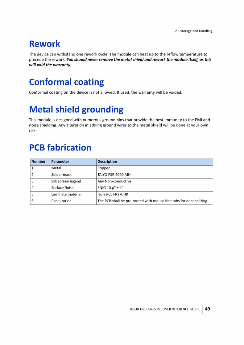
ReworkThe device can withstand one rework cycle. The module can heat up to the reflow temperature to precede the rework. You should never remove the metal shield and rework the module itself, as this will void the warranty.
Conformal coatingConformal coating on the device is not allowed. If used, the warranty will be voided.
Metal shield groundingThis module is designed with numerous ground pins that provide the best immunity to the EMI and noise shielding. Any alteration in adding ground wires to the metal shield will be done at your own risk.
PCB fabricationNumber Parameter Description
1 Metal Copper
2 Solder mask TAIYO PSR 4000 MH
3 Silk screen legend Any Non-conductive
4 Surface finish ENIG 10 µ" ± 4"
5 Laminate material Isola PCL FR370HR
6 Panelization The PCB shall be pre-routed with mouse bite tabs for depanelizing.

A
BISON DR + GNSS RECEIVER REFERENCE GUIDE 50
A P P E N D I X
HIPPO Protocol A
In this appendix:
Soft event and fatal error logging and reporting
Available HIPPO messages
System class messages
HIPPO protocol rules
Command messages
Report class
Event log queue
This chapter describes the HIPPO protocol.
The Bison firmware implements a sub-set of the HIPPO messages described in the HIPPO Protocol Specification.
BISON DR + GNSS RECEIVER REFERENCE GUIDE
A – HIPPO Protocol
51
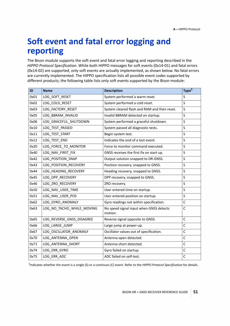
Soft event and fatal error logging and reportingThe Bison module supports the soft event and fatal error logging and reporting described in the HIPPO Protocol Specification. While both HIPPO messages for soft events (0x14-01) and fatal errors (0x14-02) are supported, only soft events are actually implemented, as shown below. No fatal errors are currently implemented. The HIPPO specification lists all possible event codes supported by different products; the following table lists only soft events supported by the Bison module:
ID Name Description Type1
1Indicates whether the event is a single (S) or a continuos (C) event. Refer to the HIPPO Protocol Specification for details.
0x01 LOG_SOFT_RESET System performed a warm reset. S
0x02 LOG_COLD_RESET System performed a cold reset. S
0x03 LOG_FACTORY_RESET System cleared flash and RAM and then reset. S
0x05 LOG_BBRAM_INVALID Invalid BBRAM detected on startup. S
0x06 LOG_GRACEFUL_SHUTDOWN System performed a graceful shutdown. S
0x10 LOG_TEST_PASSED System passed all diagnostic tests. S
0x11 LOG_TEST_START Begin system test. S
0x12 LOG_TEST_END Indicates the end of a test event. S
0x20 LOG_FORCE_TO_MONITOR Force to monitor command executed. S
0x40 LOG_NAV_FIRST_FIX GNSS receives the first fix on start up. S
0x42 LOG_POSITION_SNAP Output solution snapped to DR-GNSS. S
0x43 LOG_POSITION_RECOVERY Position recovery, snapped to GNSS. S
0x44 LOG_HEADING_RECOVERY Heading recovery, snapped to GNSS. S
0x45 LOG_DPP_RECOVERY DPP recovery, snapped to GNSS. S
0x46 LOG_ZRO_RECOVERY ZRO recovery. S
0x50 LOG_NAV_USER_TIME User entered time on startup. S
0x51 LOG_NAV_USER_POS User entered position on startup. S
0x62 LOG_GYRO_ANOMALY Gyro readings not within specification. C
0x63 LOG_NO_TACHO_WHILE_MOVING No speed signal input when GNSS detects motion.
C
0x65 LOG_REVERSE_GNSS_DISAGREE Reverse signal opposite to GNSS. C
0x66 LOG_LARGE_JUMP Large jump at power-up. C
0x67 LOG_OSCILLATOR_ANOMALY Oscillator values out of specification. C
0x70 LOG_ANTENNA_OPEN Antenna open detected. C
0x71 LOG_ANTENNA_SHORT Antenna short detected. C
0x74 LOG_ERR_GYRO Gyro failed on startup. C
0x75 LOG_ERR_ADC ADC failed on self-test. C
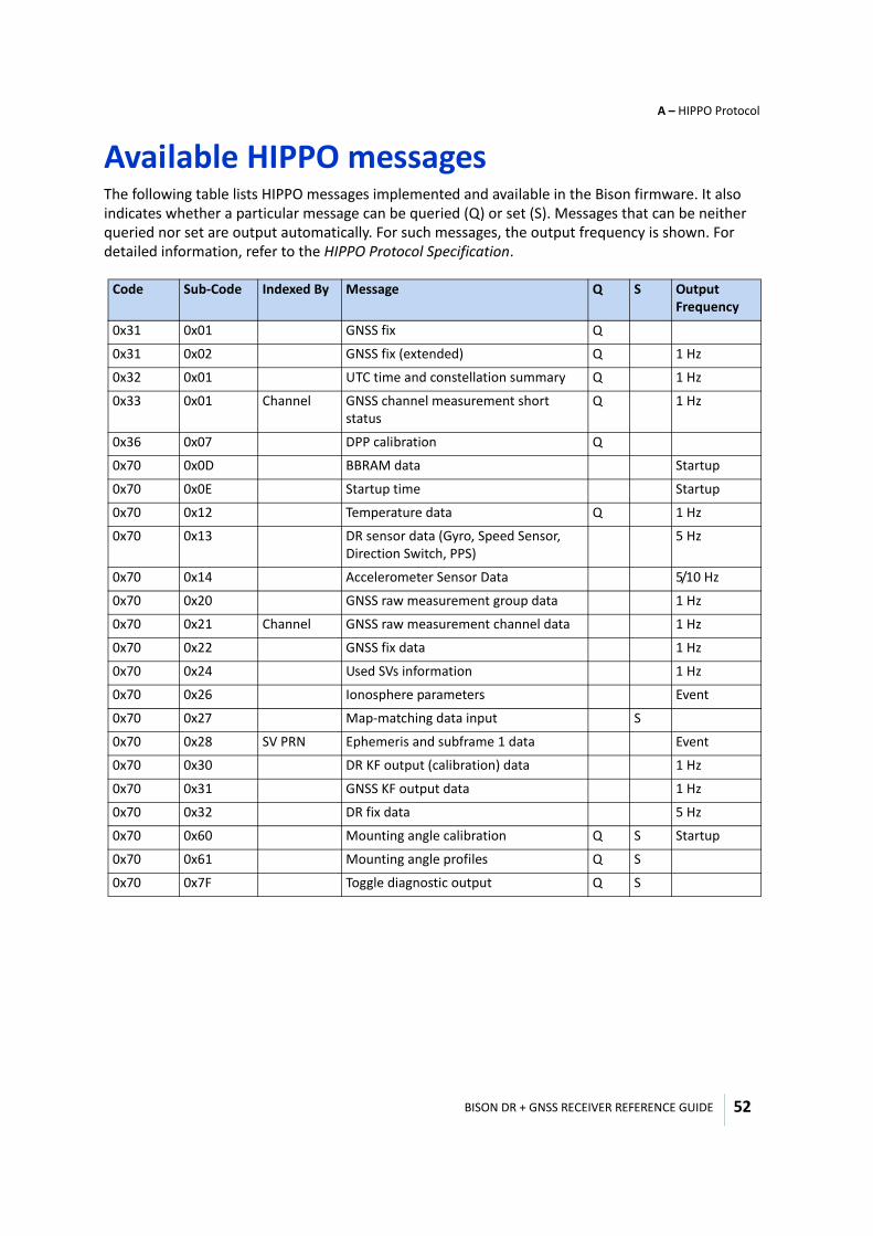
BISON DR + GNSS RECEIVER REFERENCE GUIDE
A – HIPPO Protocol
52
Available HIPPO messagesThe following table lists HIPPO messages implemented and available in the Bison firmware. It also indicates whether a particular message can be queried (Q) or set (S). Messages that can be neither queried nor set are output automatically. For such messages, the output frequency is shown. For detailed information, refer to the HIPPO Protocol Specification.
Code Sub-Code Indexed By Message Q S Output Frequency
0x31 0x01 GNSS fix Q
0x31 0x02 GNSS fix (extended) Q 1 Hz
0x32 0x01 UTC time and constellation summary Q 1 Hz
0x33 0x01 Channel GNSS channel measurement short status
Q 1 Hz
0x36 0x07 DPP calibration Q
0x70 0x0D BBRAM data Startup
0x70 0x0E Startup time Startup
0x70 0x12 Temperature data Q 1 Hz
0x70 0x13 DR sensor data (Gyro, Speed Sensor, Direction Switch, PPS)
5 Hz
0x70 0x14 Accelerometer Sensor Data 5/10 Hz
0x70 0x20 GNSS raw measurement group data 1 Hz
0x70 0x21 Channel GNSS raw measurement channel data 1 Hz
0x70 0x22 GNSS fix data 1 Hz
0x70 0x24 Used SVs information 1 Hz
0x70 0x26 Ionosphere parameters Event
0x70 0x27 Map-matching data input S
0x70 0x28 SV PRN Ephemeris and subframe 1 data Event
0x70 0x30 DR KF output (calibration) data 1 Hz
0x70 0x31 GNSS KF output data 1 Hz
0x70 0x32 DR fix data 5 Hz
0x70 0x60 Mounting angle calibration Q S Startup
0x70 0x61 Mounting angle profiles Q S
0x70 0x7F Toggle diagnostic output Q S
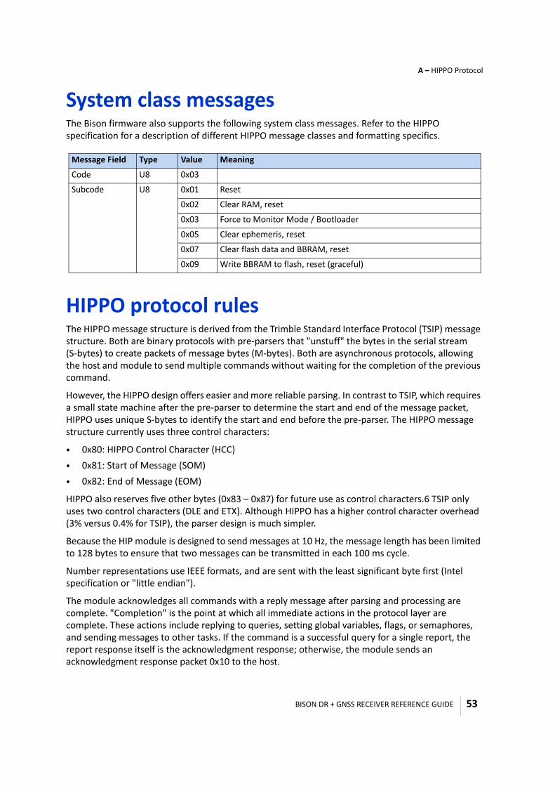
BISON DR + GNSS RECEIVER REFERENCE GUIDE
A – HIPPO Protocol
53
System class messagesThe Bison firmware also supports the following system class messages. Refer to the HIPPO specification for a description of different HIPPO message classes and formatting specifics.
HIPPO protocol rulesThe HIPPO message structure is derived from the Trimble Standard Interface Protocol (TSIP) message structure. Both are binary protocols with pre-parsers that "unstuff" the bytes in the serial stream (S-bytes) to create packets of message bytes (M-bytes). Both are asynchronous protocols, allowing the host and module to send multiple commands without waiting for the completion of the previous command.
However, the HIPPO design offers easier and more reliable parsing. In contrast to TSIP, which requires a small state machine after the pre-parser to determine the start and end of the message packet, HIPPO uses unique S-bytes to identify the start and end before the pre-parser. The HIPPO message structure currently uses three control characters:
• 0x80: HIPPO Control Character (HCC)• 0x81: Start of Message (SOM)• 0x82: End of Message (EOM)
HIPPO also reserves five other bytes (0x83 – 0x87) for future use as control characters.6 TSIP only uses two control characters (DLE and ETX). Although HIPPO has a higher control character overhead (3% versus 0.4% for TSIP), the parser design is much simpler.
Because the HIP module is designed to send messages at 10 Hz, the message length has been limited to 128 bytes to ensure that two messages can be transmitted in each 100 ms cycle.
Number representations use IEEE formats, and are sent with the least significant byte first (Intel specification or "little endian").
The module acknowledges all commands with a reply message after parsing and processing are complete. "Completion" is the point at which all immediate actions in the protocol layer are complete. These actions include replying to queries, setting global variables, flags, or semaphores, and sending messages to other tasks. If the command is a successful query for a single report, the report response itself is the acknowledgment response; otherwise, the module sends an acknowledgment response packet 0x10 to the host.
Message Field Type Value Meaning
Code U8 0x03
Subcode U8 0x01 Reset
0x02 Clear RAM, reset
0x03 Force to Monitor Mode / Bootloader
0x05 Clear ephemeris, reset
0x07 Clear flash data and BBRAM, reset
0x09 Write BBRAM to flash, reset (graceful)
BISON DR + GNSS RECEIVER REFERENCE GUIDE
A – HIPPO Protocol
54
There are two general types of messages: report messages and command messages.
General message structure rulesThe byte SOM only occurs as an S-byte (in the serial stream) at the start of a message. The byte EOM only occurs as an S-byte at the end of a message. From the SOM byte until the following EOM byte, the following structure rules apply:
• The first two S-bytes are the Parser Code PCOD and Parser Subcode PSUB. These specify a unique parser for the data bytes. PCOD and PSUB never have values of 0x80 to 0x87, and so cannot be confused for control characters.
• Depending on PCOD and PSUB, the next byte may be an index byte INDEX. INDEX never has a value of 0x80 to 0x87, and so cannot be confused for a control character. Examples of an index are a channel number and a satellite PRN. All indexed messages with the same parser code and subcode must have the same length, format, and data structure.
• The byte HCC only occurs as an S-byte as a "stuffing" character that is used to pad certain messages to a constant length, as defined in System class, page 60. It may appear before CS or any of the data bytes.
• The value of the checksum M-byte CS is such that the 8-bit sum of the M-bytes from SOM to EOM inclusive is zero. If the checksum is between 0x80 and 0x87, it is stuffed with the HCC character 0x80.
• The number of data bytes per message is limited to 128. Counting the bytes for the SOM, parser code, parser subcode, checksum, EOM, and index, the total number of M-bytes can as many as 134. Data is not valid until the message is complete and the checksum agrees.
• HIPPO ignores any bytes between messages (from EOM to the following SOM), unless the bytes have values between 0x80 and 0x87. This feature allows ASCII messages such as NMEA or TAIP to be interspersed with HIPPO messages. TSIP messages and other binary protocols in general cannot be interspersed with HIPPO messages.
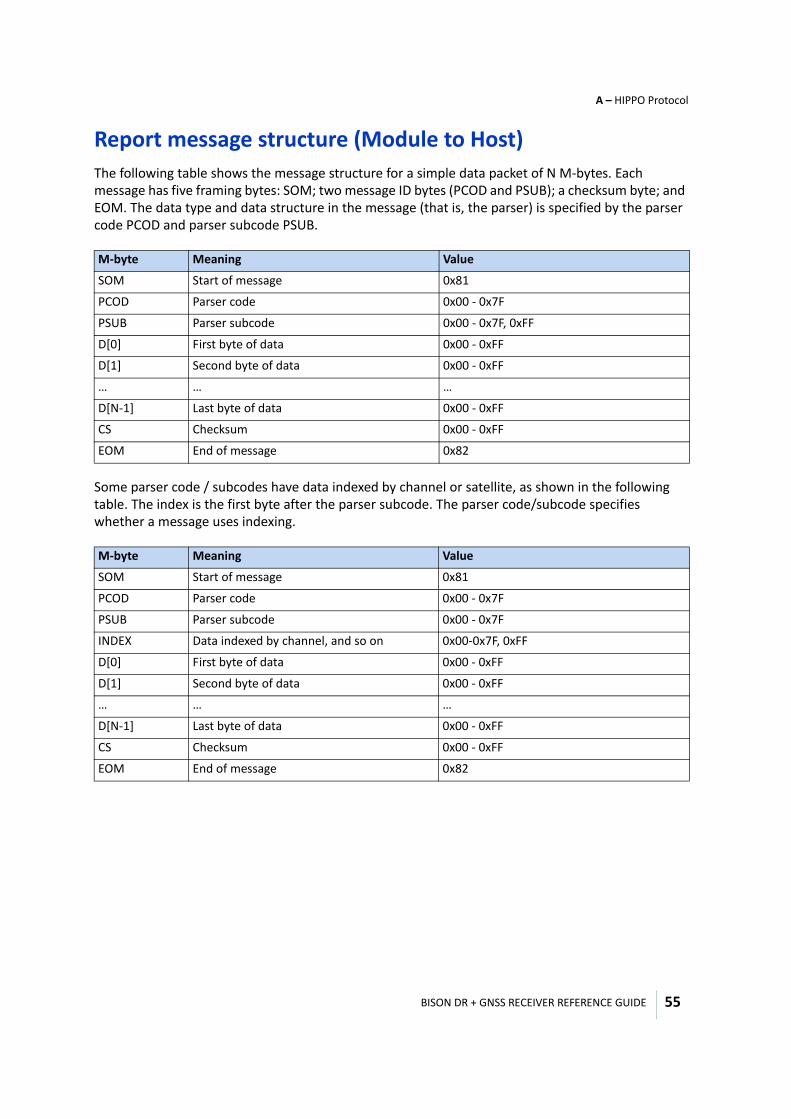
BISON DR + GNSS RECEIVER REFERENCE GUIDE
A – HIPPO Protocol
55
Report message structure (Module to Host)The following table shows the message structure for a simple data packet of N M-bytes. Each message has five framing bytes: SOM; two message ID bytes (PCOD and PSUB); a checksum byte; and EOM. The data type and data structure in the message (that is, the parser) is specified by the parser code PCOD and parser subcode PSUB.
Some parser code / subcodes have data indexed by channel or satellite, as shown in the following table. The index is the first byte after the parser subcode. The parser code/subcode specifies whether a message uses indexing.
M-byte Meaning Value
SOM Start of message 0x81
PCOD Parser code 0x00 - 0x7F
PSUB Parser subcode 0x00 - 0x7F, 0xFF
D[0] First byte of data 0x00 - 0xFF
D[1] Second byte of data 0x00 - 0xFF
… … …
D[N-1] Last byte of data 0x00 - 0xFF
CS Checksum 0x00 - 0xFF
EOM End of message 0x82
M-byte Meaning Value
SOM Start of message 0x81
PCOD Parser code 0x00 - 0x7F
PSUB Parser subcode 0x00 - 0x7F
INDEX Data indexed by channel, and so on 0x00-0x7F, 0xFF
D[0] First byte of data 0x00 - 0xFF
D[1] Second byte of data 0x00 - 0xFF
… … …
D[N-1] Last byte of data 0x00 - 0xFF
CS Checksum 0x00 - 0xFF
EOM End of message 0x82
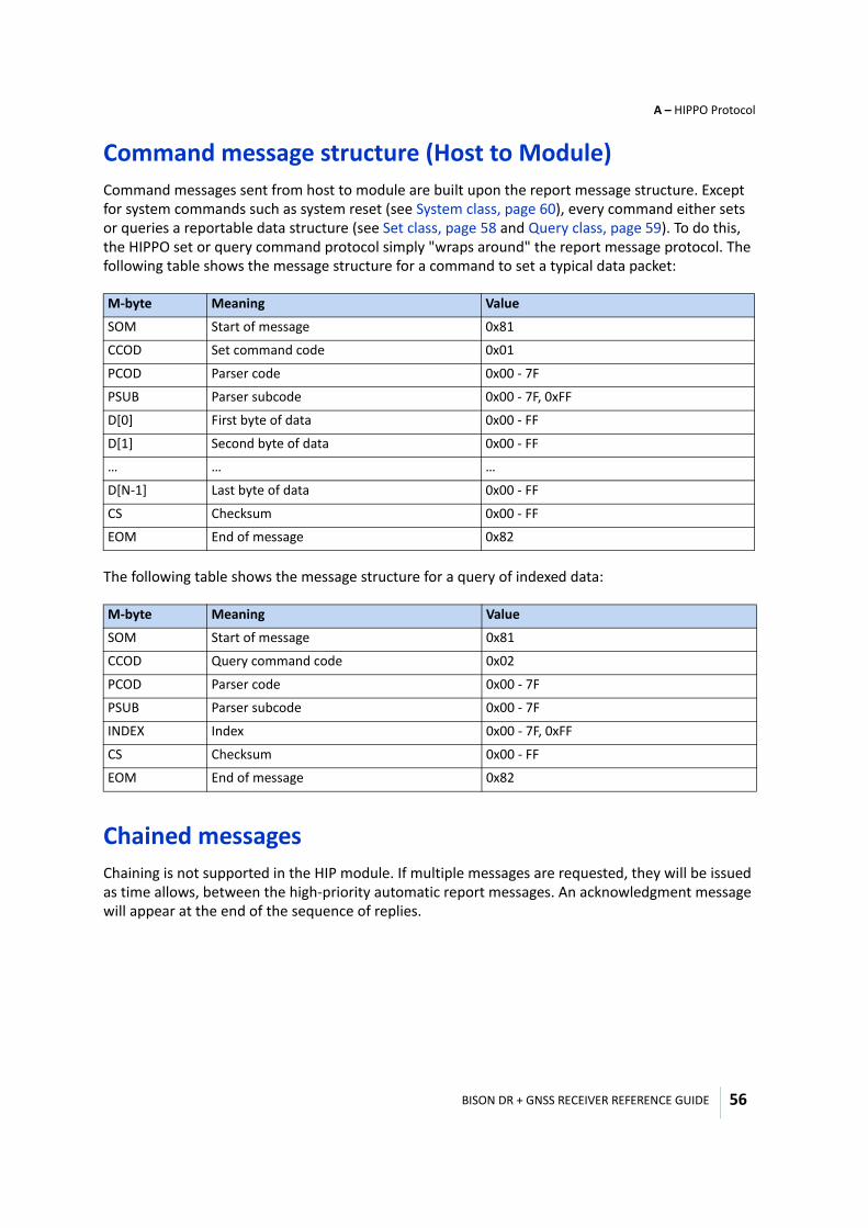
BISON DR + GNSS RECEIVER REFERENCE GUIDE
A – HIPPO Protocol
56
Command message structure (Host to Module)Command messages sent from host to module are built upon the report message structure. Except for system commands such as system reset (see System class, page 60), every command either sets or queries a reportable data structure (see Set class, page 58 and Query class, page 59). To do this, the HIPPO set or query command protocol simply "wraps around" the report message protocol. The following table shows the message structure for a command to set a typical data packet:
The following table shows the message structure for a query of indexed data:
Chained messagesChaining is not supported in the HIP module. If multiple messages are requested, they will be issued as time allows, between the high-priority automatic report messages. An acknowledgment message will appear at the end of the sequence of replies.
M-byte Meaning Value
SOM Start of message 0x81
CCOD Set command code 0x01
PCOD Parser code 0x00 - 7F
PSUB Parser subcode 0x00 - 7F, 0xFF
D[0] First byte of data 0x00 - FF
D[1] Second byte of data 0x00 - FF
… … …
D[N-1] Last byte of data 0x00 - FF
CS Checksum 0x00 - FF
EOM End of message 0x82
M-byte Meaning Value
SOM Start of message 0x81
CCOD Query command code 0x02
PCOD Parser code 0x00 - 7F
PSUB Parser subcode 0x00 - 7F
INDEX Index 0x00 - 7F, 0xFF
CS Checksum 0x00 - FF
EOM End of message 0x82
BISON DR + GNSS RECEIVER REFERENCE GUIDE
A – HIPPO Protocol
57
Post-formatting: HCC stuffing before transmissionWhenever an M-byte in the data fields or the checksum field is equal to one of the control characters (0x80 – 0x87), it generates two S-bytes — that is, the M-byte generates the S-byte pair (0x80, M-byte, and 0x7F).
Pre-parsing: HCC unstuffing after receptionPre-parsing (assembly of the M-bytes) occurs as S-bytes are received. HIPPO pre-parsing begins with the appearance of the SOM S-byte and ends with the appearance of the EOM S-byte:
• Whenever the S-byte is SOM, a new message structure opens with room for 132 M-bytes. The first M-byte of a message is always SOM.
• Whenever the S-byte HCC appears, it does not generate a new M-byte: It generates a signal to or the following S-byte with 0x80 to create the next M-byte. Otherwise, the M-byte is the same as the S-byte.
• If the S-byte is EOM, the message structure is closed. The last M-byte of a message is always EOM.
• The last M-byte before the EOM is the checksum. It is computed so that the sum of all M-bytes, including the SOM, the EOM, and the checksum, is zero.
After pre-parsing is complete, the message packet is ready to be parsed into structures according to the rules in Report class, page 60 and Event log queue, page 70. The parser code and subcodes are the second and third M-bytes, directly after the SOM. The data will start on the fourth (non-indexed data) or fifth (indexed data) M-byte.
Possible pre-parser errors include:
• Two SOMs appear without an EOM in between.• HCC occurs in the first two bytes (parser code and subcode).• The byte following HCC is not equal to the 7 LSBs of a HIPPO control character.• Control characters appear between message (after EOM but before the next SOM).• No EOM appears in the first 134 M-bytes.
Command messages HIPPO has three classes of command message packets:
• Set parameters: This "wraps around" the report message structure of the parameter(s) to be set. • Query parameters: This calls out the report code and subcode (and index, if applicable) of the
required reports. • System commands
The module always acknowledges a command in one of two ways.
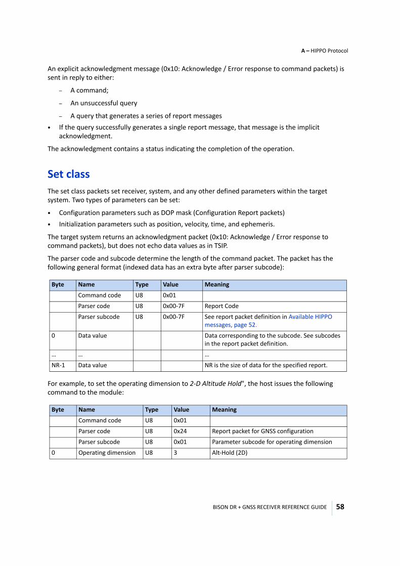
BISON DR + GNSS RECEIVER REFERENCE GUIDE
A – HIPPO Protocol
58
An explicit acknowledgment message (0x10: Acknowledge / Error response to command packets) is sent in reply to either:
– A command;
– An unsuccessful query
– A query that generates a series of report messages• If the query successfully generates a single report message, that message is the implicit
acknowledgment.
The acknowledgment contains a status indicating the completion of the operation.
Set classThe set class packets set receiver, system, and any other defined parameters within the target system. Two types of parameters can be set:
• Configuration parameters such as DOP mask (Configuration Report packets)• Initialization parameters such as position, velocity, time, and ephemeris.
The target system returns an acknowledgment packet (0x10: Acknowledge / Error response to command packets), but does not echo data values as in TSIP.
The parser code and subcode determine the length of the command packet. The packet has the following general format (indexed data has an extra byte after parser subcode):
For example, to set the operating dimension to 2-D Altitude Hold", the host issues the following command to the module:
Byte Name Type Value Meaning
Command code U8 0x01
Parser code U8 0x00-7F Report Code
Parser subcode U8 0x00-7F See report packet definition in Available HIPPO messages, page 52.
0 Data value Data corresponding to the subcode. See subcodes in the report packet definition.
… … …
NR-1 Data value NR is the size of data for the specified report.
Byte Name Type Value Meaning
Command code U8 0x01
Parser code U8 0x24 Report packet for GNSS configuration
Parser subcode U8 0x01 Parameter subcode for operating dimension
0 Operating dimension U8 3 Alt-Hold (2D)
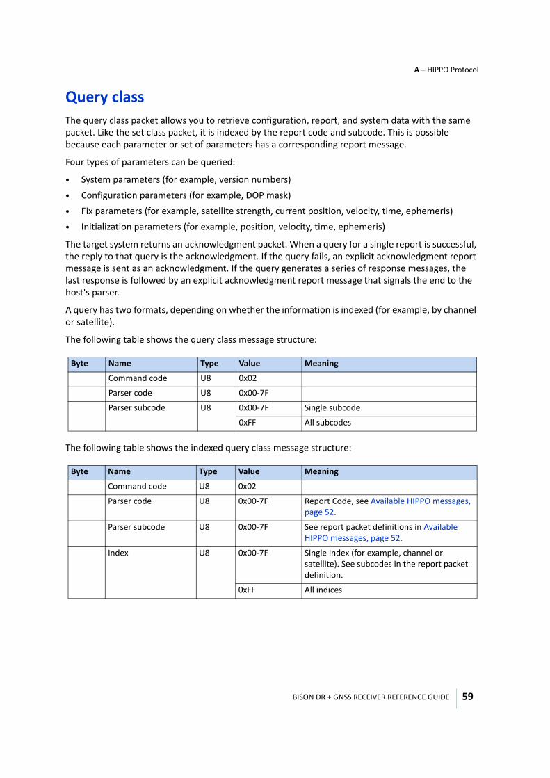
BISON DR + GNSS RECEIVER REFERENCE GUIDE
A – HIPPO Protocol
59
Query classThe query class packet allows you to retrieve configuration, report, and system data with the same packet. Like the set class packet, it is indexed by the report code and subcode. This is possible because each parameter or set of parameters has a corresponding report message.
Four types of parameters can be queried:
• System parameters (for example, version numbers) • Configuration parameters (for example, DOP mask) • Fix parameters (for example, satellite strength, current position, velocity, time, ephemeris)• Initialization parameters (for example, position, velocity, time, ephemeris)
The target system returns an acknowledgment packet. When a query for a single report is successful, the reply to that query is the acknowledgment. If the query fails, an explicit acknowledgment report message is sent as an acknowledgment. If the query generates a series of response messages, the last response is followed by an explicit acknowledgment report message that signals the end to the host's parser.
A query has two formats, depending on whether the information is indexed (for example, by channel or satellite).
The following table shows the query class message structure:
The following table shows the indexed query class message structure:
Byte Name Type Value Meaning
Command code U8 0x02
Parser code U8 0x00-7F
Parser subcode U8 0x00-7F Single subcode
0xFF All subcodes
Byte Name Type Value Meaning
Command code U8 0x02
Parser code U8 0x00-7F Report Code, see Available HIPPO messages, page 52.
Parser subcode U8 0x00-7F See report packet definitions in Available HIPPO messages, page 52.
Index U8 0x00-7F Single index (for example, channel or satellite). See subcodes in the report packet definition.
0xFF All indices
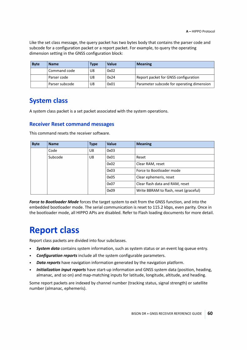
BISON DR + GNSS RECEIVER REFERENCE GUIDE
A – HIPPO Protocol
60
Like the set class message, the query packet has two bytes body that contains the parser code and subcode for a configuration packet or a report packet. For example, to query the operating dimension setting in the GNSS configuration block:
System classA system class packet is a set packet associated with the system operations.
Receiver Reset command messages This command resets the receiver software.
Force to Bootloader Mode forces the target system to exit from the GNSS function, and into the embedded bootloader mode. The serial communication is reset to 115.2 kbps, even parity. Once in the bootloader mode, all HIPPO APIs are disabled. Refer to Flash loading documents for more detail.
Report classReport class packets are divided into four subclasses.
• System data contains system information, such as system status or an event log queue entry. • Configuration reports include all the system configurable parameters. • Data reports have navigation information generated by the navigation platform.• Initialization input reports have start-up information and GNSS system data (position, heading,
almanac, and so on) and map-matching inputs for latitude, longitude, altitude, and heading.
Some report packets are indexed by channel number (tracking status, signal strength) or satellite number (almanac, ephemeris).
Byte Name Type Value Meaning
Command code U8 0x02
Parser code U8 0x24 Report packet for GNSS configuration
Parser subcode U8 0x01 Parameter subcode for operating dimension
Byte Name Type Value Meaning
Code U8 0x03
Subcode U8 0x01 Reset
0x02 Clear RAM, reset
0x03 Force to Bootloader mode
0x05 Clear ephemeris, reset
0x07 Clear flash data and RAM, reset
0x09 Write BBRAM to flash, reset (graceful)
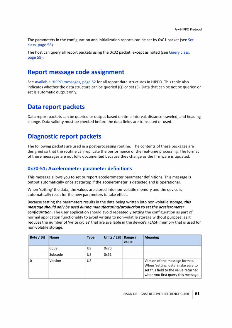
BISON DR + GNSS RECEIVER REFERENCE GUIDE
A – HIPPO Protocol
61
The parameters in the configuration and initialization reports can be set by 0x01 packet (see Set class, page 58).
The host can query all report packets using the 0x02 packet, except as noted (see Query class, page 59).
Report message code assignmentSee Available HIPPO messages, page 52 for all report data structures in HIPPO. This table also indicates whether the data structure can be queried (Q) or set (S). Data that can be not be queried or set is automatic output only.
Data report packets Data report packets can be queried or output based on time interval, distance traveled, and heading change. Data validity must be checked before the data fields are translated or used.
Diagnostic report packetsThe following packets are used in a post-processing routine. The contents of these packages are designed so that the routine can replicate the performance of the real-time processing. The format of these messages are not fully documented because they change as the firmware is updated.
0x70-51: Accelerometer parameter definitionsThis message allows you to set or report accelerometer parameter definitions. This message is output automatically once at startup if the accelerometer is detected and is operational.
When 'setting' the data, the values are stored into non-volatile memory and the device is automatically reset for the new parameters to take effect.
Because setting the parameters results in the data being written into non-volatile storage, this message should only be used during manufacturing/production to set the accelerometer configuration. The user application should avoid repeatedly setting the configuration as part of normal application functionality to avoid writing to non-volatile storage without purpose, as it reduces the number of 'write cycles' that are available in the device's FLASH memory that is used for non-volatile storage.
Byte / Bit Name Type Units / LSB Range / value
Meaning
Code U8 0x70
Subcode U8 0x51
0 Version U8 Version of the message format. When 'setting' data, make sure to set this field to the value returned when you first query this message.
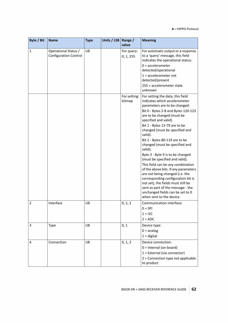
BISON DR + GNSS RECEIVER REFERENCE GUIDE
A – HIPPO Protocol
62
1 Operational Status / Configuration Control
U8 For query: 0, 1, 255
For automatic output or a response to a 'query' message, this field indicates the operational status:0 = accelerometer detected/operational1 = accelerometer not detected/present255 = accelerometer state unknown
For setting: bitmap
For setting the data, this field indicates which accelerometer parameters are to be changed:Bit 0 - Bytes 2-8 and Bytes 120-123 are to be changed (must be specified and valid).Bit 1 - Bytes 13-79 are to be changed (must be specified and valid).Bit 2 - Bytes 80-119 are to be changed (must be specified and valid).Byte 3 - Byte 9 is to be changed (must be specified and valid).This field can be any combination of the above bits. If any parameters are not being changed (i.e. the corresponding configuration bit is not set), the fields must still be sent as part of the message - the unchanged fields can be set to 0 when sent to the device.
2 Interface U8 0, 1, 2 Communication interface:0 = SPI1 = I2C2 = ADC
3 Type U8 0, 1 Device type:0 = analog1 = digital
4 Connection U8 0, 1, 2 Device connection:0 = Internal (on-board)1 = External (via connector)2 = Connection type not applicable to product
Byte / Bit Name Type Units / LSB Range / value
Meaning
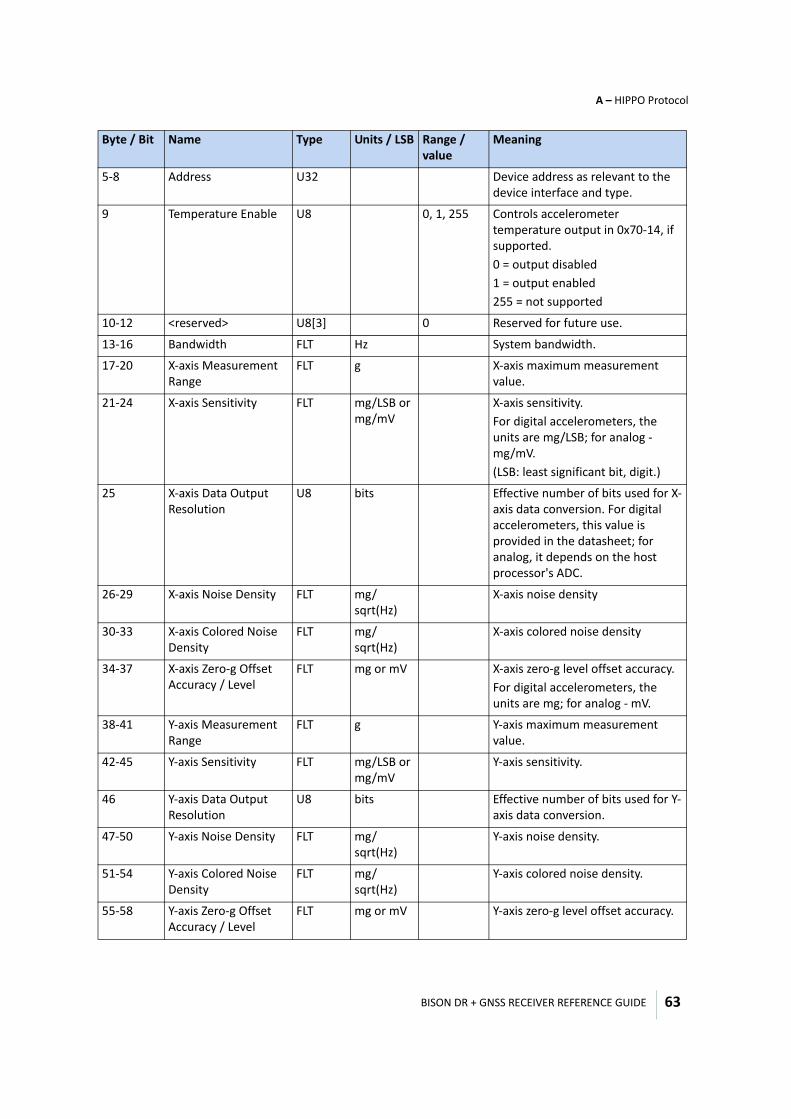
BISON DR + GNSS RECEIVER REFERENCE GUIDE
A – HIPPO Protocol
63
5-8 Address U32 Device address as relevant to the device interface and type.
9 Temperature Enable U8 0, 1, 255 Controls accelerometer temperature output in 0x70-14, if supported.0 = output disabled1 = output enabled255 = not supported
10-12 <reserved> U8[3] 0 Reserved for future use.
13-16 Bandwidth FLT Hz System bandwidth.
17-20 X-axis Measurement Range
FLT g X-axis maximum measurement value.
21-24 X-axis Sensitivity FLT mg/LSB or mg/mV
X-axis sensitivity.For digital accelerometers, the units are mg/LSB; for analog - mg/mV.(LSB: least significant bit, digit.)
25 X-axis Data Output Resolution
U8 bits Effective number of bits used for X-axis data conversion. For digital accelerometers, this value is provided in the datasheet; for analog, it depends on the host processor's ADC.
26-29 X-axis Noise Density FLT mg/ sqrt(Hz)
X-axis noise density
30-33 X-axis Colored Noise Density
FLT mg/ sqrt(Hz)
X-axis colored noise density
34-37 X-axis Zero-g Offset Accuracy / Level
FLT mg or mV X-axis zero-g level offset accuracy.For digital accelerometers, the units are mg; for analog - mV.
38-41 Y-axis Measurement Range
FLT g Y-axis maximum measurement value.
42-45 Y-axis Sensitivity FLT mg/LSB or mg/mV
Y-axis sensitivity.
46 Y-axis Data Output Resolution
U8 bits Effective number of bits used for Y-axis data conversion.
47-50 Y-axis Noise Density FLT mg/ sqrt(Hz)
Y-axis noise density.
51-54 Y-axis Colored Noise Density
FLT mg/ sqrt(Hz)
Y-axis colored noise density.
55-58 Y-axis Zero-g Offset Accuracy / Level
FLT mg or mV Y-axis zero-g level offset accuracy.
Byte / Bit Name Type Units / LSB Range / value
Meaning
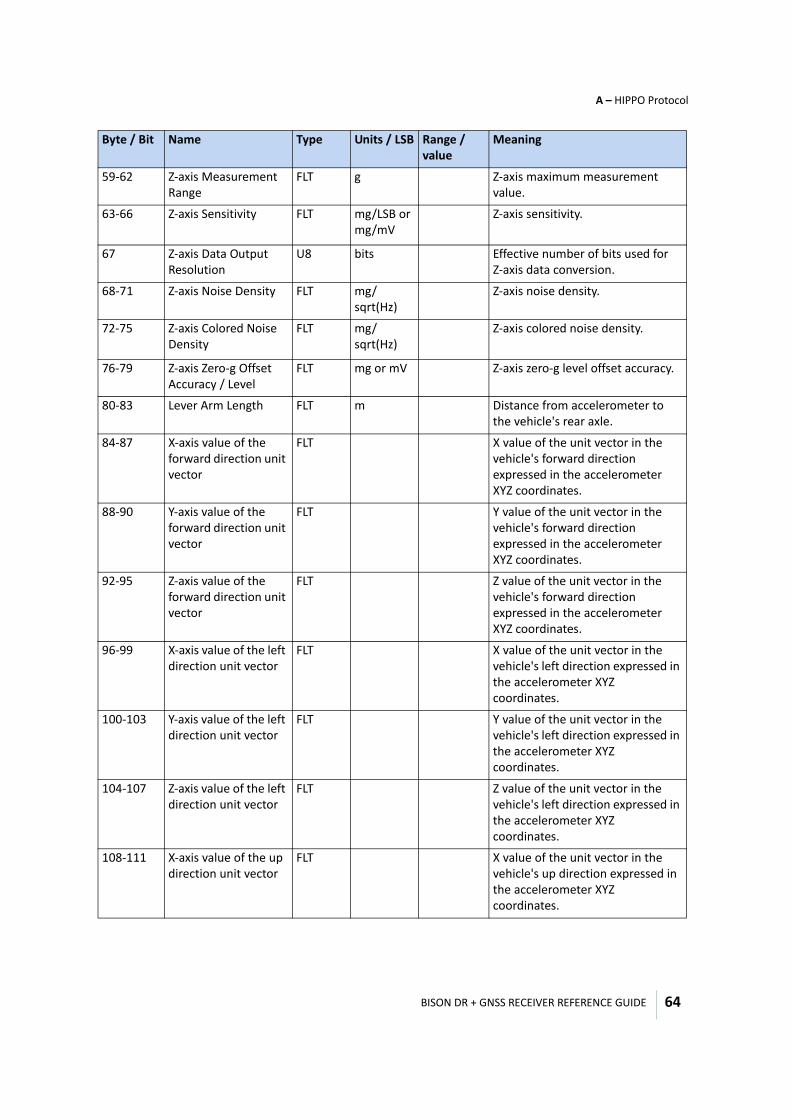
BISON DR + GNSS RECEIVER REFERENCE GUIDE
A – HIPPO Protocol
64
59-62 Z-axis Measurement Range
FLT g Z-axis maximum measurement value.
63-66 Z-axis Sensitivity FLT mg/LSB or mg/mV
Z-axis sensitivity.
67 Z-axis Data Output Resolution
U8 bits Effective number of bits used for Z-axis data conversion.
68-71 Z-axis Noise Density FLT mg/ sqrt(Hz)
Z-axis noise density.
72-75 Z-axis Colored Noise Density
FLT mg/ sqrt(Hz)
Z-axis colored noise density.
76-79 Z-axis Zero-g Offset Accuracy / Level
FLT mg or mV Z-axis zero-g level offset accuracy.
80-83 Lever Arm Length FLT m Distance from accelerometer to the vehicle's rear axle.
84-87 X-axis value of the forward direction unit vector
FLT X value of the unit vector in the vehicle's forward direction expressed in the accelerometer XYZ coordinates.
88-90 Y-axis value of the forward direction unit vector
FLT Y value of the unit vector in the vehicle's forward direction expressed in the accelerometer XYZ coordinates.
92-95 Z-axis value of the forward direction unit vector
FLT Z value of the unit vector in the vehicle's forward direction expressed in the accelerometer XYZ coordinates.
96-99 X-axis value of the left direction unit vector
FLT X value of the unit vector in the vehicle's left direction expressed in the accelerometer XYZ coordinates.
100-103 Y-axis value of the left direction unit vector
FLT Y value of the unit vector in the vehicle's left direction expressed in the accelerometer XYZ coordinates.
104-107 Z-axis value of the left direction unit vector
FLT Z value of the unit vector in the vehicle's left direction expressed in the accelerometer XYZ coordinates.
108-111 X-axis value of the up direction unit vector
FLT X value of the unit vector in the vehicle's up direction expressed in the accelerometer XYZ coordinates.
Byte / Bit Name Type Units / LSB Range / value
Meaning
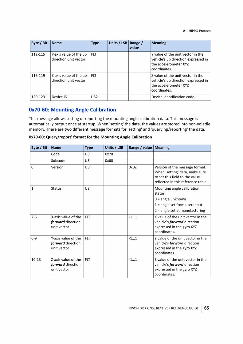
BISON DR + GNSS RECEIVER REFERENCE GUIDE
A – HIPPO Protocol
65
0x70-60: Mounting Angle CalibrationThis message allows setting or reporting the mounting angle calibration data. This message is automatically output once at startup. When 'setting' the data, the values are stored into non-volatile memory. There are two different message formats for 'setting' and 'querying/reporting' the data.
0x70-60: Query/report' format for the Mounting Angle Calibration
112-115 Y-axis value of the up direction unit vector
FLT Y value of the unit vector in the vehicle's up direction expressed in the accelerometer XYZ coordinates.
116-119 Z-axis value of the up direction unit vector
FLT Z value of the unit vector in the vehicle's up direction expressed in the accelerometer XYZ coordinates.
120-123 Device ID U32 Device identification code.
Byte / Bit Name Type Units / LSB Range / value Meaning
Code U8 0x70
Subcode U8 0x60
0 Version U8 0x02 Version of the message format. When 'setting' data, make sure to set this field to the value reflected in this reference table.
1 Status U8 Mounting angle calibration status:0 = angle unknown1 = angle set from user input2 = angle set at manufacturing
2-5 X-axis value of the forward direction unit vector
FLT -1…1 X value of the unit vector in the vehicle's forward direction expressed in the gyro XYZ coordinates.
6-9 Y-axis value of the forward direction unit vector
FLT -1…1 Y value of the unit vector in the vehicle's forward direction expressed in the gyro XYZ coordinates.
10-13 Z-axis value of the forward direction unit vector
FLT -1…1 Z value of the unit vector in the vehicle's forward direction expressed in the gyro XYZ coordinates.
Byte / Bit Name Type Units / LSB Range / value
Meaning
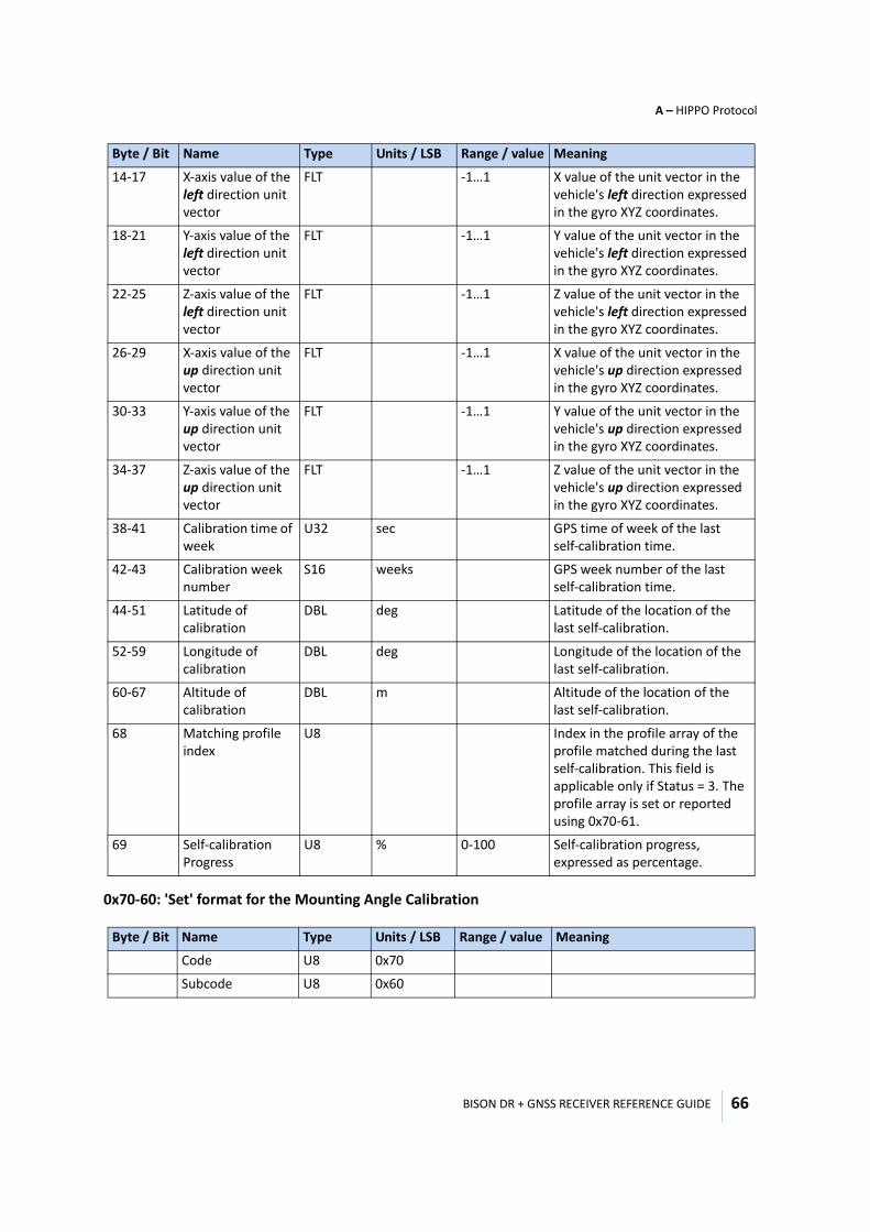
BISON DR + GNSS RECEIVER REFERENCE GUIDE
A – HIPPO Protocol
66
0x70-60: 'Set' format for the Mounting Angle Calibration
14-17 X-axis value of the left direction unit vector
FLT -1…1 X value of the unit vector in the vehicle's left direction expressed in the gyro XYZ coordinates.
18-21 Y-axis value of the left direction unit vector
FLT -1…1 Y value of the unit vector in the vehicle's left direction expressed in the gyro XYZ coordinates.
22-25 Z-axis value of the left direction unit vector
FLT -1…1 Z value of the unit vector in the vehicle's left direction expressed in the gyro XYZ coordinates.
26-29 X-axis value of the up direction unit vector
FLT -1…1 X value of the unit vector in the vehicle's up direction expressed in the gyro XYZ coordinates.
30-33 Y-axis value of the up direction unit vector
FLT -1…1 Y value of the unit vector in the vehicle's up direction expressed in the gyro XYZ coordinates.
34-37 Z-axis value of the up direction unit vector
FLT -1…1 Z value of the unit vector in the vehicle's up direction expressed in the gyro XYZ coordinates.
38-41 Calibration time of week
U32 sec GPS time of week of the last self-calibration time.
42-43 Calibration week number
S16 weeks GPS week number of the last self-calibration time.
44-51 Latitude of calibration
DBL deg Latitude of the location of the last self-calibration.
52-59 Longitude of calibration
DBL deg Longitude of the location of the last self-calibration.
60-67 Altitude of calibration
DBL m Altitude of the location of the last self-calibration.
68 Matching profile index
U8 Index in the profile array of the profile matched during the last self-calibration. This field is applicable only if Status = 3. The profile array is set or reported using 0x70-61.
69 Self-calibration Progress
U8 % 0-100 Self-calibration progress, expressed as percentage.
Byte / Bit Name Type Units / LSB Range / value Meaning
Code U8 0x70
Subcode U8 0x60
Byte / Bit Name Type Units / LSB Range / value Meaning
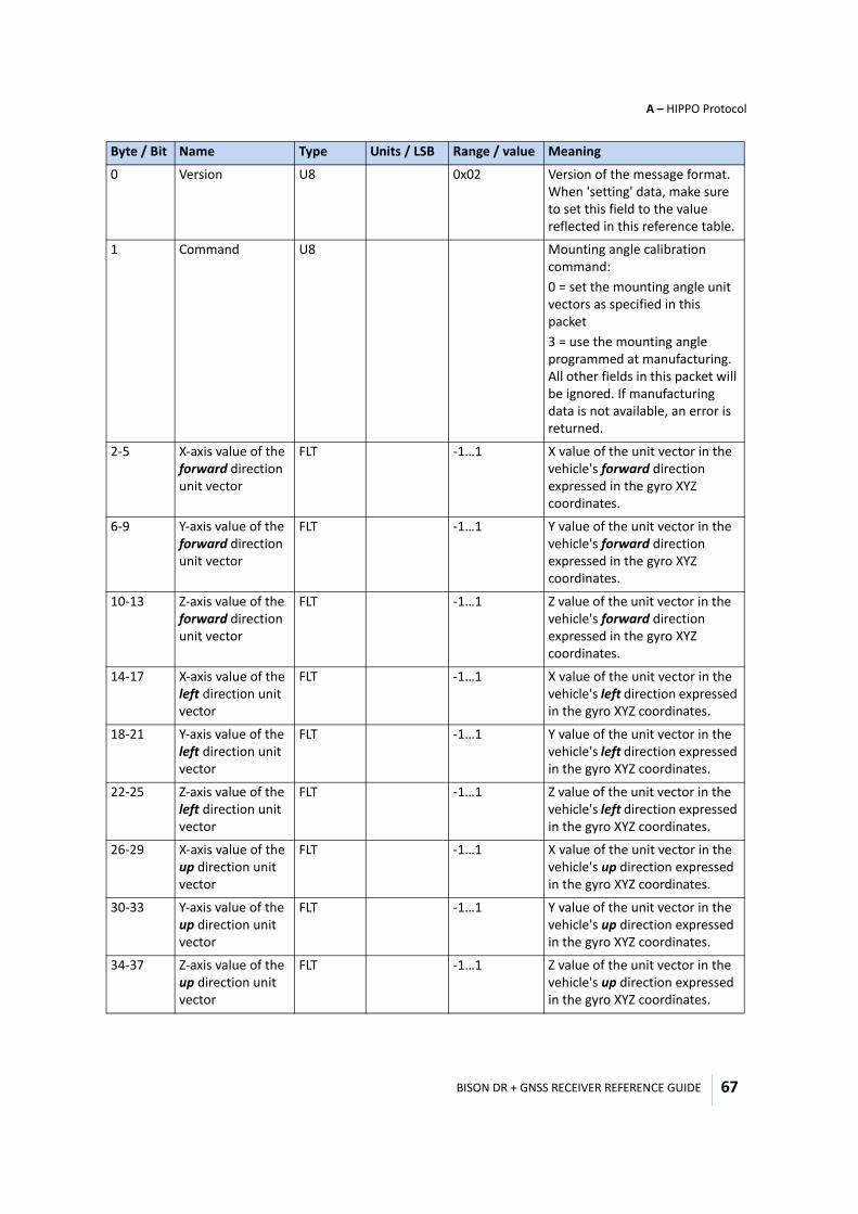
BISON DR + GNSS RECEIVER REFERENCE GUIDE
A – HIPPO Protocol
67
0 Version U8 0x02 Version of the message format. When 'setting' data, make sure to set this field to the value reflected in this reference table.
1 Command U8 Mounting angle calibration command:0 = set the mounting angle unit vectors as specified in this packet3 = use the mounting angle programmed at manufacturing. All other fields in this packet will be ignored. If manufacturing data is not available, an error is returned.
2-5 X-axis value of the forward direction unit vector
FLT -1…1 X value of the unit vector in the vehicle's forward direction expressed in the gyro XYZ coordinates.
6-9 Y-axis value of the forward direction unit vector
FLT -1…1 Y value of the unit vector in the vehicle's forward direction expressed in the gyro XYZ coordinates.
10-13 Z-axis value of the forward direction unit vector
FLT -1…1 Z value of the unit vector in the vehicle's forward direction expressed in the gyro XYZ coordinates.
14-17 X-axis value of the left direction unit vector
FLT -1…1 X value of the unit vector in the vehicle's left direction expressed in the gyro XYZ coordinates.
18-21 Y-axis value of the left direction unit vector
FLT -1…1 Y value of the unit vector in the vehicle's left direction expressed in the gyro XYZ coordinates.
22-25 Z-axis value of the left direction unit vector
FLT -1…1 Z value of the unit vector in the vehicle's left direction expressed in the gyro XYZ coordinates.
26-29 X-axis value of the up direction unit vector
FLT -1…1 X value of the unit vector in the vehicle's up direction expressed in the gyro XYZ coordinates.
30-33 Y-axis value of the up direction unit vector
FLT -1…1 Y value of the unit vector in the vehicle's up direction expressed in the gyro XYZ coordinates.
34-37 Z-axis value of the up direction unit vector
FLT -1…1 Z value of the unit vector in the vehicle's up direction expressed in the gyro XYZ coordinates.
Byte / Bit Name Type Units / LSB Range / value Meaning
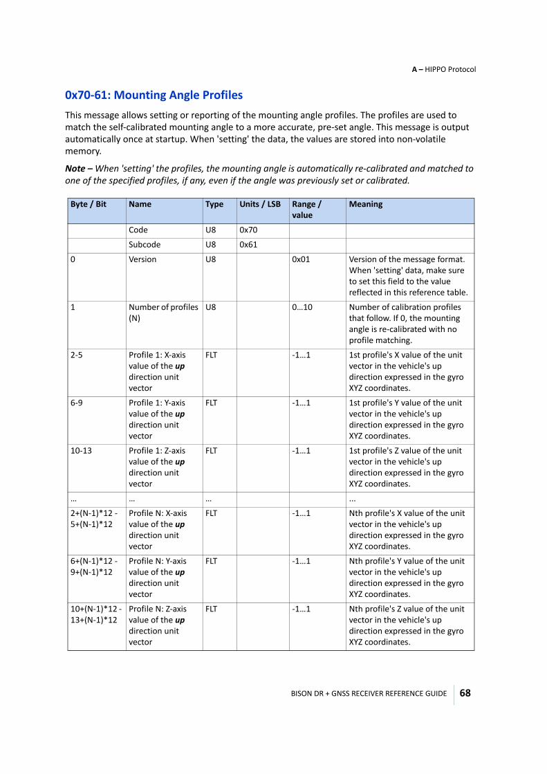
BISON DR + GNSS RECEIVER REFERENCE GUIDE
A – HIPPO Protocol
68
0x70-61: Mounting Angle ProfilesThis message allows setting or reporting of the mounting angle profiles. The profiles are used to match the self-calibrated mounting angle to a more accurate, pre-set angle. This message is output automatically once at startup. When 'setting' the data, the values are stored into non-volatile memory.
Note – When 'setting' the profiles, the mounting angle is automatically re-calibrated and matched to one of the specified profiles, if any, even if the angle was previously set or calibrated.
Byte / Bit Name Type Units / LSB Range / value
Meaning
Code U8 0x70
Subcode U8 0x61
0 Version U8 0x01 Version of the message format. When 'setting' data, make sure to set this field to the value reflected in this reference table.
1 Number of profiles (N)
U8 0…10 Number of calibration profiles that follow. If 0, the mounting angle is re-calibrated with no profile matching.
2-5 Profile 1: X-axis value of the up direction unit vector
FLT -1…1 1st profile's X value of the unit vector in the vehicle's up direction expressed in the gyro XYZ coordinates.
6-9 Profile 1: Y-axis value of the up direction unit vector
FLT -1…1 1st profile's Y value of the unit vector in the vehicle's up direction expressed in the gyro XYZ coordinates.
10-13 Profile 1: Z-axis value of the up direction unit vector
FLT -1…1 1st profile's Z value of the unit vector in the vehicle's up direction expressed in the gyro XYZ coordinates.
… … … ...
2+(N-1)*12 - 5+(N-1)*12
Profile N: X-axis value of the up direction unit vector
FLT -1…1 Nth profile's X value of the unit vector in the vehicle's up direction expressed in the gyro XYZ coordinates.
6+(N-1)*12 - 9+(N-1)*12
Profile N: Y-axis value of the up direction unit vector
FLT -1…1 Nth profile's Y value of the unit vector in the vehicle's up direction expressed in the gyro XYZ coordinates.
10+(N-1)*12 - 13+(N-1)*12
Profile N: Z-axis value of the up direction unit vector
FLT -1…1 Nth profile's Z value of the unit vector in the vehicle's up direction expressed in the gyro XYZ coordinates.
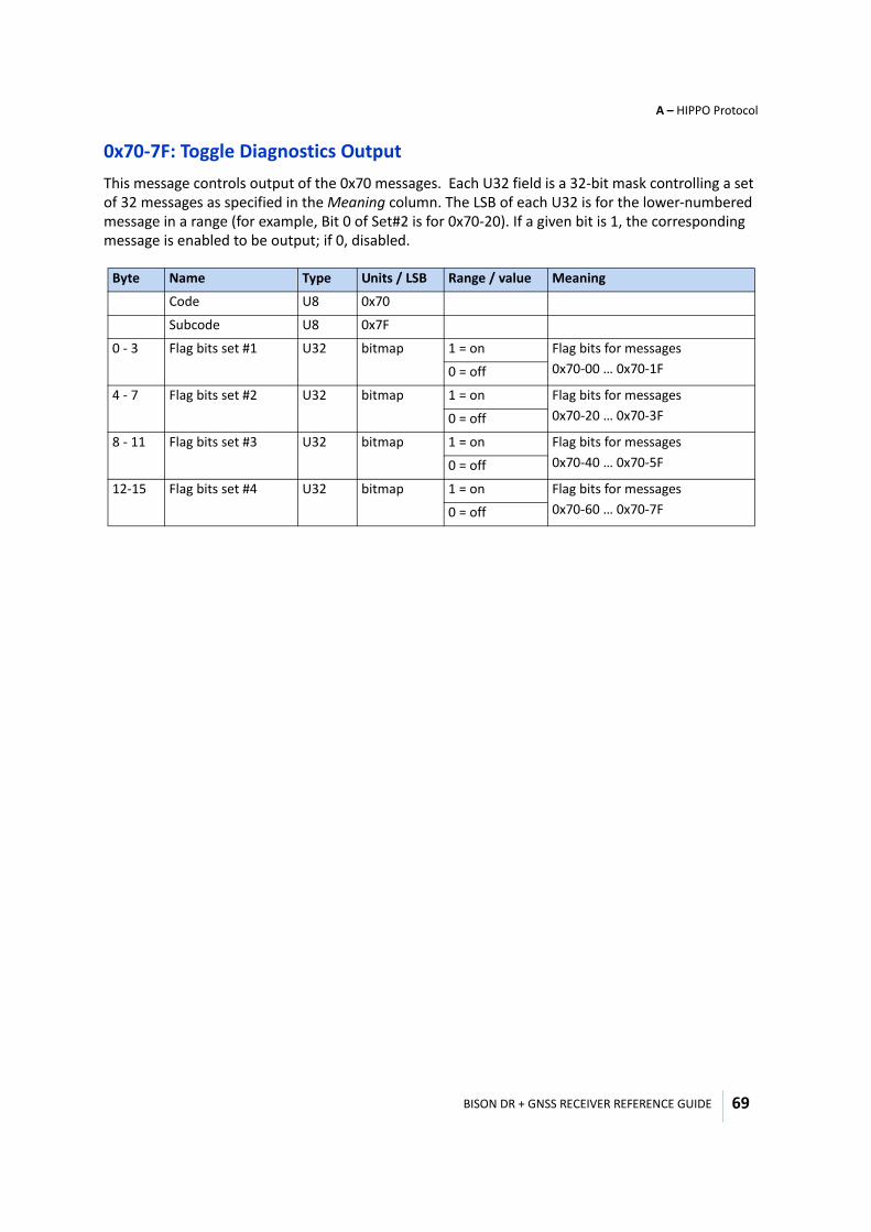
BISON DR + GNSS RECEIVER REFERENCE GUIDE
A – HIPPO Protocol
69
0x70-7F: Toggle Diagnostics OutputThis message controls output of the 0x70 messages. Each U32 field is a 32-bit mask controlling a set of 32 messages as specified in the Meaning column. The LSB of each U32 is for the lower-numbered message in a range (for example, Bit 0 of Set#2 is for 0x70-20). If a given bit is 1, the corresponding message is enabled to be output; if 0, disabled.
Byte Name Type Units / LSB Range / value Meaning
Code U8 0x70
Subcode U8 0x7F
0 - 3 Flag bits set #1 U32 bitmap 1 = on Flag bits for messages0x70-00 … 0x70-1F 0 = off
4 - 7 Flag bits set #2 U32 bitmap 1 = on Flag bits for messages0x70-20 … 0x70-3F0 = off
8 - 11 Flag bits set #3 U32 bitmap 1 = on Flag bits for messages0x70-40 … 0x70-5F0 = off
12-15 Flag bits set #4 U32 bitmap 1 = on Flag bits for messages0x70-60 … 0x70-7F0 = off
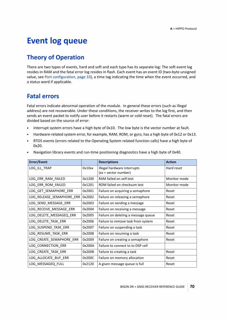
BISON DR + GNSS RECEIVER REFERENCE GUIDE
A – HIPPO Protocol
70
Event log queue
Theory of OperationThere are two types of events, hard and soft and each type has its separate log: The soft event log resides in RAM and the fatal error log resides in flash. Each event has an event ID (two-byte unsigned value, see Port configuration, page 33), a time tag indicating the time when the event occurred, and a status word if applicable.
Fatal errorsFatal errors indicate abnormal operation of the module. In general these errors (such as illegal address) are not recoverable. Under these conditions, the receiver writes to the log first, and then sends an event packet to notify user before it restarts (warm or cold reset). The fatal errors are divided based on the source of error:
• Interrupt system errors have a high byte of 0x10. The low byte is the vector number at fault. • Hardware-related system error, for example, RAM, ROM, or gyro, has a high byte of 0x12 or 0x13.• RTOS events (errors related to the Operating System related function calls) have a high byte of
0x20. • Navigation library events and run-time positioning diagnostics have a high byte of 0x40.
Error/Event Descriptions Action
LOG_ILL_TRAP 0x10xx Illegal hardware interrupts (xx = vector number)
Hard reset
LOG_ERR_RAM_FAILED 0x1200 RAM failed on self-test Monitor mode
LOG_ERR_ROM_FAILED 0x1201 ROM failed on checksum test Monitor mode
LOG_GET_SEMAPHORE_ERR 0x2001 Failure on acquiring a semaphore Reset
LOG_RELEASE_SEMAPHORE_ERR 0x2002 Failure on releasing a semaphore Reset
LOG_SEND_MESSAGE_ERR 0x2003 Failure on sending a message Reset
LOG_RECEIVE_MESSAGE_ERR 0x2004 Failure on receiving a message Reset
LOG_DELETE_MESSAGEQ_ERR 0x2005 Failure on deleting a message queue Reset
LOG_DELETE_TASK_ERR 0x2006 Failure to remove task from system Reset
LOG_SUSPEND_TASK_ERR 0x2007 Failure on suspending a task Reset
LOG_RESUME_TASK_ERR 0x2008 Failure on resuming a task Reset
LOG_CREATE_SEMAPHORE_ERR 0x2009 Failure on creating a semaphore Reset
LOG_CONNECTION_ERR 0x200A Failure to connect to Io-DSP cell
LOG_CREATE_TASK_ERR 0x200B Failure to creating a task Reset
LOG_ALLOCATE_BUF_ERR 0x200C Failure on memory allocation Reset
LOG_MESSAGEQ_FULL 0x2120 A given message queue is full Reset
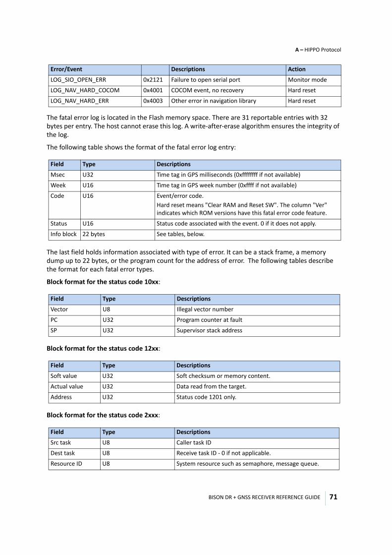
BISON DR + GNSS RECEIVER REFERENCE GUIDE
A – HIPPO Protocol
71
The fatal error log is located in the Flash memory space. There are 31 reportable entries with 32 bytes per entry. The host cannot erase this log. A write-after-erase algorithm ensures the integrity of the log.
The following table shows the format of the fatal error log entry:
The last field holds information associated with type of error. It can be a stack frame, a memory dump up to 22 bytes, or the program count for the address of error. The following tables describe the format for each fatal error types.
Block format for the status code 10xx:
Block format for the status code 12xx:
Block format for the status code 2xxx:
LOG_SIO_OPEN_ERR 0x2121 Failure to open serial port Monitor mode
LOG_NAV_HARD_COCOM 0x4001 COCOM event, no recovery Hard reset
LOG_NAV_HARD_ERR 0x4003 Other error in navigation library Hard reset
Field Type Descriptions
Msec U32 Time tag in GPS milliseconds (0xffffffff if not available)
Week U16 Time tag in GPS week number (0xffff if not available)
Code U16 Event/error code. Hard reset means "Clear RAM and Reset SW". The column "Ver" indicates which ROM versions have this fatal error code feature.
Status U16 Status code associated with the event. 0 if it does not apply.
Info block 22 bytes See tables, below.
Field Type Descriptions
Vector U8 Illegal vector number
PC U32 Program counter at fault
SP U32 Supervisor stack address
Field Type Descriptions
Soft value U32 Soft checksum or memory content.
Actual value U32 Data read from the target.
Address U32 Status code 1201 only.
Field Type Descriptions
Src task U8 Caller task ID
Dest task U8 Receive task ID - 0 if not applicable.
Resource ID U8 System resource such as semaphore, message queue.
Error/Event Descriptions Action
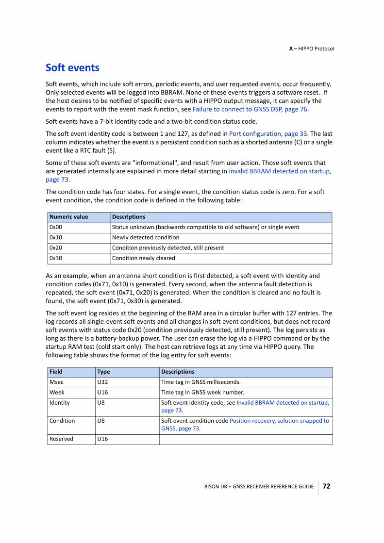
BISON DR + GNSS RECEIVER REFERENCE GUIDE
A – HIPPO Protocol
72
Soft eventsSoft events, which include soft errors, periodic events, and user requested events, occur frequently. Only selected events will be logged into BBRAM. None of these events triggers a software reset. If the host desires to be notified of specific events with a HIPPO output message, it can specify the events to report with the event mask function, see Failure to connect to GNSS DSP, page 76.
Soft events have a 7-bit identity code and a two-bit condition status code.
The soft event identity code is between 1 and 127, as defined in Port configuration, page 33. The last column indicates whether the event is a persistent condition such as a shorted antenna (C) or a single event like a RTC fault (S).
Some of these soft events are "informational", and result from user action. Those soft events that are generated internally are explained in more detail starting in Invalid BBRAM detected on startup, page 73.
The condition code has four states. For a single event, the condition status code is zero. For a soft event condition, the condition code is defined in the following table:
As an example, when an antenna short condition is first detected, a soft event with identity and condition codes (0x71, 0x10) is generated. Every second, when the antenna fault detection is repeated, the soft event (0x71, 0x20) is generated. When the condition is cleared and no fault is found, the soft event (0x71, 0x30) is generated.
The soft event log resides at the beginning of the RAM area in a circular buffer with 127 entries. The log records all single-event soft events and all changes in soft event conditions, but does not record soft events with status code 0x20 (condition previously detected, still present). The log persists as long as there is a battery-backup power. The user can erase the log via a HIPPO command or by the startup RAM test (cold start only). The host can retrieve logs at any time via HIPPO query. The following table shows the format of the log entry for soft events:
Numeric value Descriptions
0x00 Status unknown (backwards compatible to old software) or single event
0x10 Newly detected condition
0x20 Condition previously detected, still present
0x30 Condition newly cleared
Field Type Descriptions
Msec U32 Time tag in GNSS milliseconds.
Week U16 Time tag in GNSS week number.
Identity U8 Soft event identity code, see Invalid BBRAM detected on startup, page 73.
Condition U8 Soft event condition code Position recovery, solution snapped to GNSS, page 73.
Reserved U16
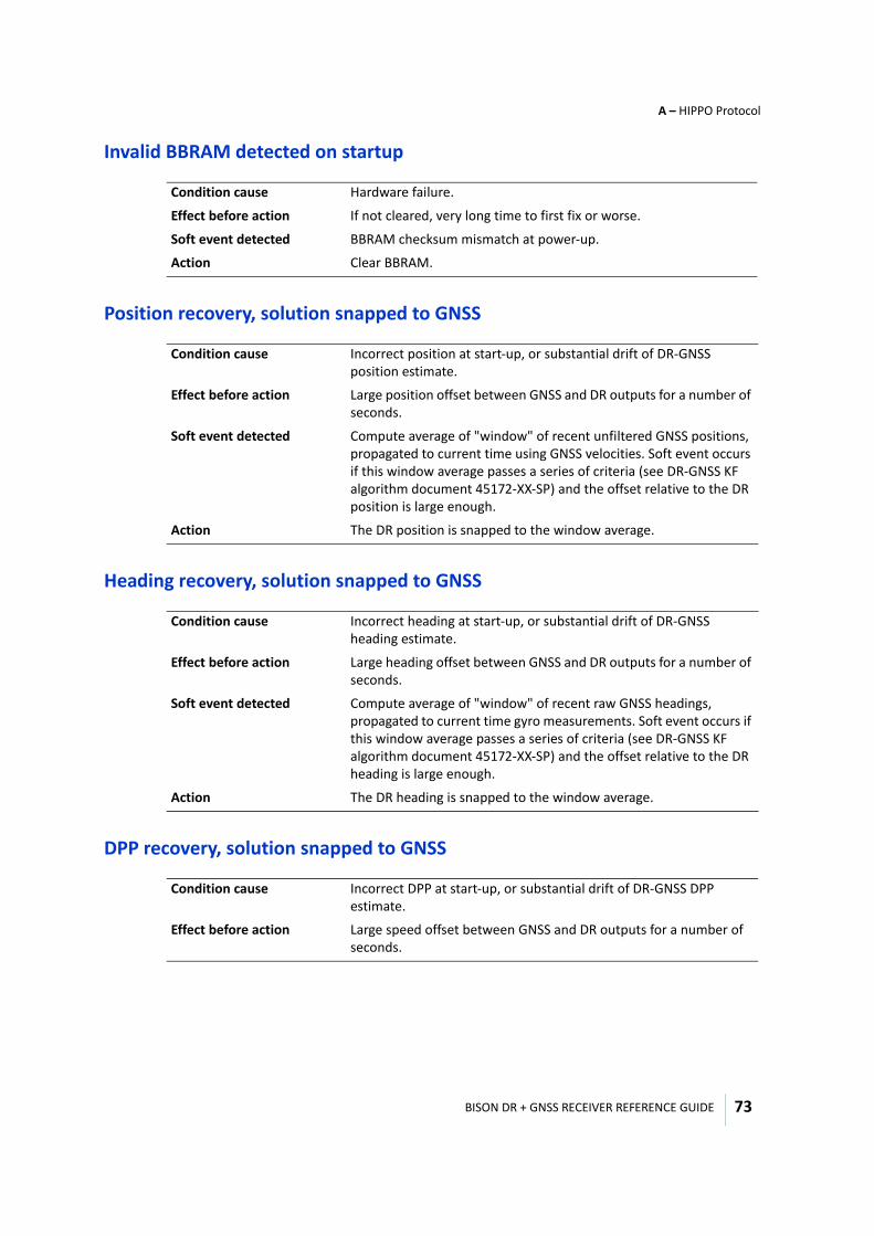
BISON DR + GNSS RECEIVER REFERENCE GUIDE
A – HIPPO Protocol
73
Invalid BBRAM detected on startup
Position recovery, solution snapped to GNSS
Heading recovery, solution snapped to GNSS
DPP recovery, solution snapped to GNSS
Condition cause Hardware failure.
Effect before action If not cleared, very long time to first fix or worse.
Soft event detected BBRAM checksum mismatch at power-up.
Action Clear BBRAM.
Condition cause Incorrect position at start-up, or substantial drift of DR-GNSS position estimate.
Effect before action Large position offset between GNSS and DR outputs for a number of seconds.
Soft event detected Compute average of "window" of recent unfiltered GNSS positions, propagated to current time using GNSS velocities. Soft event occurs if this window average passes a series of criteria (see DR-GNSS KF algorithm document 45172-XX-SP) and the offset relative to the DR position is large enough.
Action The DR position is snapped to the window average.
Condition cause Incorrect heading at start-up, or substantial drift of DR-GNSS heading estimate.
Effect before action Large heading offset between GNSS and DR outputs for a number of seconds.
Soft event detected Compute average of "window" of recent raw GNSS headings, propagated to current time gyro measurements. Soft event occurs if this window average passes a series of criteria (see DR-GNSS KF algorithm document 45172-XX-SP) and the offset relative to the DR heading is large enough.
Action The DR heading is snapped to the window average.
Condition cause Incorrect DPP at start-up, or substantial drift of DR-GNSS DPP estimate.
Effect before action Large speed offset between GNSS and DR outputs for a number of seconds.
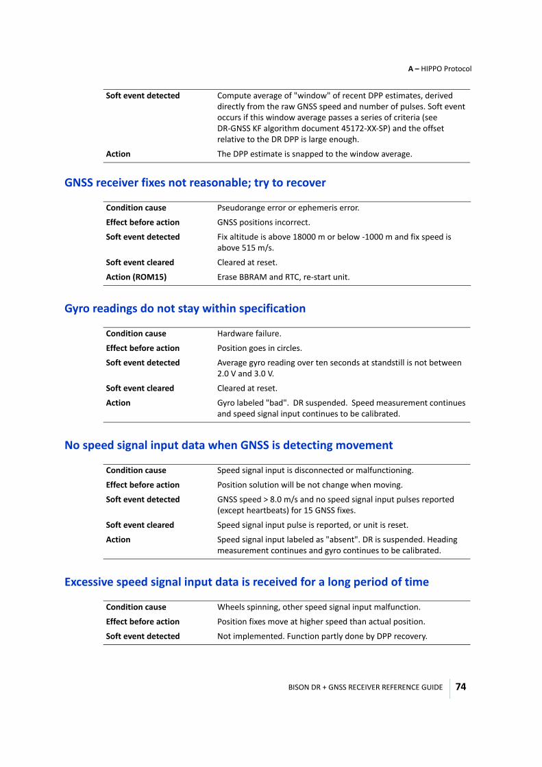
BISON DR + GNSS RECEIVER REFERENCE GUIDE
A – HIPPO Protocol
74
GNSS receiver fixes not reasonable; try to recover
Gyro readings do not stay within specification
No speed signal input data when GNSS is detecting movement
Excessive speed signal input data is received for a long period of time
Soft event detected Compute average of "window" of recent DPP estimates, derived directly from the raw GNSS speed and number of pulses. Soft event occurs if this window average passes a series of criteria (see DR-GNSS KF algorithm document 45172-XX-SP) and the offset relative to the DR DPP is large enough.
Action The DPP estimate is snapped to the window average.
Condition cause Pseudorange error or ephemeris error.
Effect before action GNSS positions incorrect.
Soft event detected Fix altitude is above 18000 m or below -1000 m and fix speed is above 515 m/s.
Soft event cleared Cleared at reset.
Action (ROM15) Erase BBRAM and RTC, re-start unit.
Condition cause Hardware failure.
Effect before action Position goes in circles.
Soft event detected Average gyro reading over ten seconds at standstill is not between 2.0 V and 3.0 V.
Soft event cleared Cleared at reset.
Action Gyro labeled "bad". DR suspended. Speed measurement continues and speed signal input continues to be calibrated.
Condition cause Speed signal input is disconnected or malfunctioning.
Effect before action Position solution will be not change when moving.
Soft event detected GNSS speed > 8.0 m/s and no speed signal input pulses reported (except heartbeats) for 15 GNSS fixes.
Soft event cleared Speed signal input pulse is reported, or unit is reset.
Action Speed signal input labeled as "absent". DR is suspended. Heading measurement continues and gyro continues to be calibrated.
Condition cause Wheels spinning, other speed signal input malfunction.
Effect before action Position fixes move at higher speed than actual position.
Soft event detected Not implemented. Function partly done by DPP recovery.
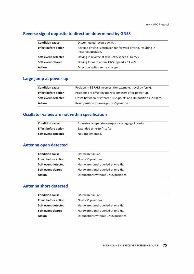
BISON DR + GNSS RECEIVER REFERENCE GUIDE
A – HIPPO Protocol
75
Reverse signal opposite to direction determined by GNSS
Large jump at power-up
Oscillator values are not within specification
Antenna open detected
Antenna short detected
Condition cause Disconnected reverse switch.
Effect before action Reverse driving is mistaken for forward driving, resulting in incorrect position.
Soft event detected Driving in reverse at raw GNSS speed > 14 m/s.
Soft event cleared Driving forward at raw GNSS speed > 14 m/s.
Action Direction switch sense changed.
Condition cause Position in BBRAM incorrect (for example, travel by ferry).
Effect before action Positions are offset by many kilometers after power-up.
Soft event detected Offset between first three GNSS points and DR position > 2000 m.
Action Reset position to average GNSS position.
Condition cause Excessive temperature response or aging of crystal.
Effect before action Extended time-to-first fix.
Soft event detected Not implemented.
Condition cause Hardware failure.
Effect before action No GNSS positions.
Soft event detected Hardware signal queried at one Hz.
Soft event cleared Hardware signal queried at one Hz.
Action DR functions without GNSS positions.
Condition cause Hardware failure.
Effect before action No GNSS positions.
Soft event detected Hardware signal queried at one Hz.
Soft event cleared Hardware signal queried at one Hz.
Action DR functions without GNSS positions.
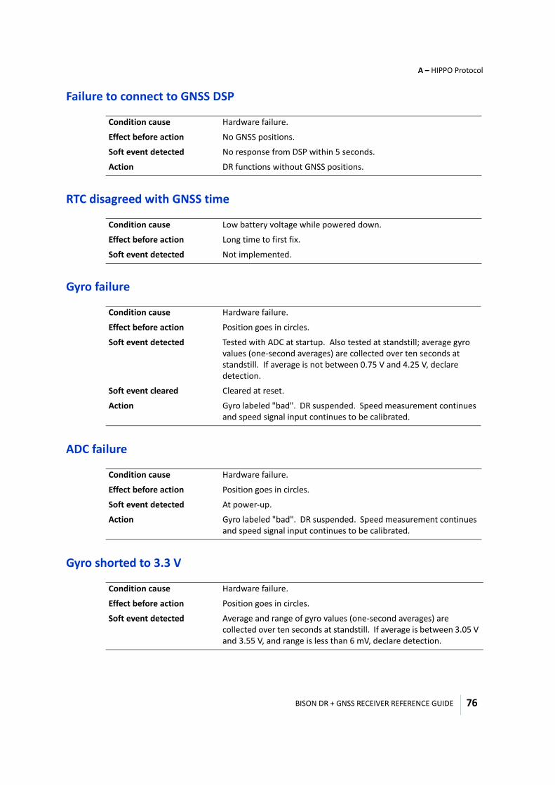
BISON DR + GNSS RECEIVER REFERENCE GUIDE
A – HIPPO Protocol
76
Failure to connect to GNSS DSP
RTC disagreed with GNSS time
Gyro failure
ADC failure
Gyro shorted to 3.3 V
Condition cause Hardware failure.
Effect before action No GNSS positions.
Soft event detected No response from DSP within 5 seconds.
Action DR functions without GNSS positions.
Condition cause Low battery voltage while powered down.
Effect before action Long time to first fix.
Soft event detected Not implemented.
Condition cause Hardware failure.
Effect before action Position goes in circles.
Soft event detected Tested with ADC at startup. Also tested at standstill; average gyro values (one-second averages) are collected over ten seconds at standstill. If average is not between 0.75 V and 4.25 V, declare detection.
Soft event cleared Cleared at reset.
Action Gyro labeled "bad". DR suspended. Speed measurement continues and speed signal input continues to be calibrated.
Condition cause Hardware failure.
Effect before action Position goes in circles.
Soft event detected At power-up.
Action Gyro labeled "bad". DR suspended. Speed measurement continues and speed signal input continues to be calibrated.
Condition cause Hardware failure.
Effect before action Position goes in circles.
Soft event detected Average and range of gyro values (one-second averages) are collected over ten seconds at standstill. If average is between 3.05 V and 3.55 V, and range is less than 6 mV, declare detection.
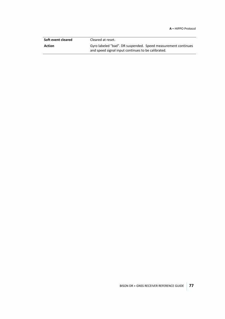
BISON DR + GNSS RECEIVER REFERENCE GUIDE
A – HIPPO Protocol
77
Soft event cleared Cleared at reset.
Action Gyro labeled "bad". DR suspended. Speed measurement continues and speed signal input continues to be calibrated.

B
BISON DR + GNSS RECEIVER REFERENCE GUIDE 78
A P P E N D I X
NMEA 0183 Protocol B
In this appendix:
Introduction
NMEA protocol overview
NMEA 0183 communication interface
NMEA 0183 message structure
Field definitions
Message options
Standard NMEA messages
Proprietary NMEA messages
This appendix provides a brief overview of the NMEA 0183 protocol, and describes both the standard and optional messages offered by the Bison firmware.
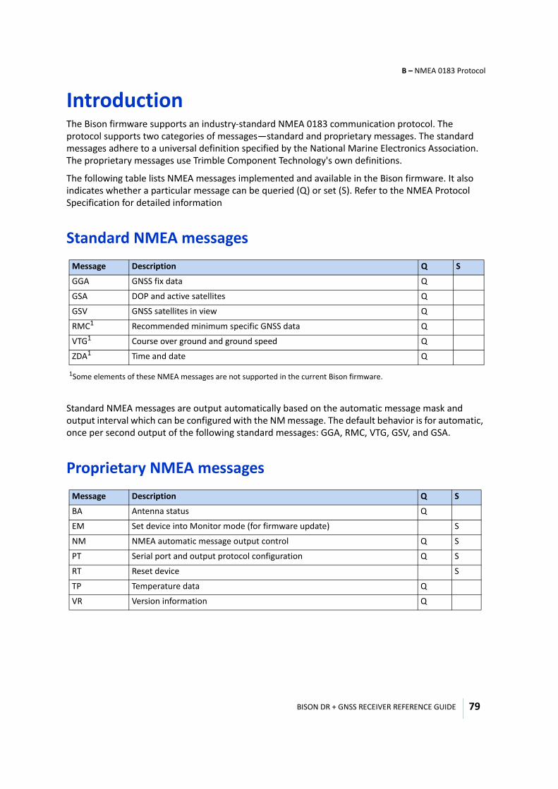
BISON DR + GNSS RECEIVER REFERENCE GUIDE
B – NMEA 0183 Protocol
79
IntroductionThe Bison firmware supports an industry-standard NMEA 0183 communication protocol. The protocol supports two categories of messages—standard and proprietary messages. The standard messages adhere to a universal definition specified by the National Marine Electronics Association. The proprietary messages use Trimble Component Technology's own definitions.
The following table lists NMEA messages implemented and available in the Bison firmware. It also indicates whether a particular message can be queried (Q) or set (S). Refer to the NMEA Protocol Specification for detailed information
Standard NMEA messages
Standard NMEA messages are output automatically based on the automatic message mask and output interval which can be configured with the NM message. The default behavior is for automatic, once per second output of the following standard messages: GGA, RMC, VTG, GSV, and GSA.
Proprietary NMEA messages
Message Description Q S
GGA GNSS fix data Q
GSA DOP and active satellites Q
GSV GNSS satellites in view Q
RMC1
1Some elements of these NMEA messages are not supported in the current Bison firmware.
Recommended minimum specific GNSS data Q
VTG1 Course over ground and ground speed Q
ZDA1 Time and date Q
Message Description Q S
BA Antenna status Q
EM Set device into Monitor mode (for firmware update) S
NM NMEA automatic message output control Q S
PT Serial port and output protocol configuration Q S
RT Reset device S
TP Temperature data Q
VR Version information Q
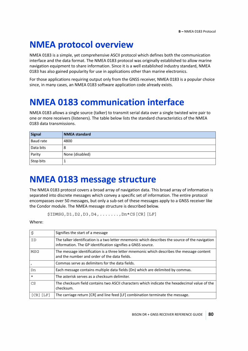
BISON DR + GNSS RECEIVER REFERENCE GUIDE
B – NMEA 0183 Protocol
80
NMEA protocol overviewNMEA 0183 is a simple, yet comprehensive ASCII protocol which defines both the communication interface and the data format. The NMEA 0183 protocol was originally established to allow marine navigation equipment to share information. Since it is a well established industry standard, NMEA 0183 has also gained popularity for use in applications other than marine electronics.
For those applications requiring output only from the GNSS receiver, NMEA 0183 is a popular choice since, in many cases, an NMEA 0183 software application code already exists.
NMEA 0183 communication interfaceNMEA 0183 allows a single source (talker) to transmit serial data over a single twisted wire pair to one or more receivers (listeners). The table below lists the standard characteristics of the NMEA 0183 data transmissions.
NMEA 0183 message structureThe NMEA 0183 protocol covers a broad array of navigation data. This broad array of information is separated into discrete messages which convey a specific set of information. The entire protocol encompasses over 50 messages, but only a sub-set of these messages apply to a GNSS receiver like the Condor module. The NMEA message structure is described below.
$IDMSG,D1,D2,D3,D4,.......,Dn*CS[CR][LF]
Where:
Signal NMEA standard
Baud rate 4800
Data bits 8
Parity None (disabled)
Stop bits 1
$ Signifies the start of a message
ID The talker identification is a two letter mnemonic which describes the source of the navigation information. The GP identification signifies a GNSS source.
MSG The message identification is a three letter mnemonic which describes the message content and the number and order of the data fields.
, Commas serve as delimiters for the data fields.
Dn Each message contains multiple data fields (Dn) which are delimited by commas.
* The asterisk serves as a checksum delimiter.
CS The checksum field contains two ASCII characters which indicate the hexadecimal value of the checksum.
[CR][LF] The carriage return [CR] and line feed [LF] combination terminate the message.
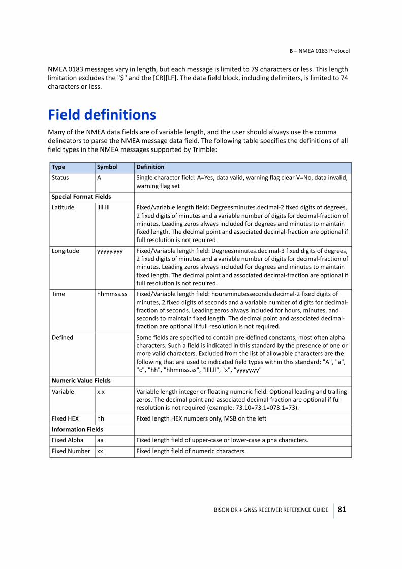
BISON DR + GNSS RECEIVER REFERENCE GUIDE
B – NMEA 0183 Protocol
81
NMEA 0183 messages vary in length, but each message is limited to 79 characters or less. This length limitation excludes the "$" and the [CR][LF]. The data field block, including delimiters, is limited to 74 characters or less.
Field definitions Many of the NMEA data fields are of variable length, and the user should always use the comma delineators to parse the NMEA message data field. The following table specifies the definitions of all field types in the NMEA messages supported by Trimble:
Type Symbol Definition
Status A Single character field: A=Yes, data valid, warning flag clear V=No, data invalid, warning flag set
Special Format Fields
Latitude llll.lll Fixed/variable length field: Degreesminutes.decimal-2 fixed digits of degrees, 2 fixed digits of minutes and a variable number of digits for decimal-fraction of minutes. Leading zeros always included for degrees and minutes to maintain fixed length. The decimal point and associated decimal-fraction are optional if full resolution is not required.
Longitude yyyyy.yyy Fixed/Variable length field: Degreesminutes.decimal-3 fixed digits of degrees, 2 fixed digits of minutes and a variable number of digits for decimal-fraction of minutes. Leading zeros always included for degrees and minutes to maintain fixed length. The decimal point and associated decimal-fraction are optional if full resolution is not required.
Time hhmmss.ss Fixed/Variable length field: hoursminutesseconds.decimal-2 fixed digits of minutes, 2 fixed digits of seconds and a variable number of digits for decimal-fraction of seconds. Leading zeros always included for hours, minutes, and seconds to maintain fixed length. The decimal point and associated decimal-fraction are optional if full resolution is not required.
Defined Some fields are specified to contain pre-defined constants, most often alpha characters. Such a field is indicated in this standard by the presence of one or more valid characters. Excluded from the list of allowable characters are the following that are used to indicated field types within this standard: "A", "a", "c", "hh", "hhmmss.ss", "llll.ll", "x", "yyyyy.yy"
Numeric Value Fields
Variable x.x Variable length integer or floating numeric field. Optional leading and trailing zeros. The decimal point and associated decimal-fraction are optional if full resolution is not required (example: 73.10=73.1=073.1=73).
Fixed HEX hh Fixed length HEX numbers only, MSB on the left
Information Fields
Fixed Alpha aa Fixed length field of upper-case or lower-case alpha characters.
Fixed Number xx Fixed length field of numeric characters
BISON DR + GNSS RECEIVER REFERENCE GUIDE
B – NMEA 0183 Protocol
82
Note – - Spaces should only be used in variable text fields. - Units of measure fields are appropriate characters from the Symbol column unless a specified unit of measure is indicated. - Fixed length field definitions show the actual number of characters. For example, a field defined to have a fixed length of 5 HEX characters is represented as hhhhh between delimiters in a sentence definition.
Message optionsAny given product can output any or all of the messages listed in the product specification or design document. Typically NMEA messages are output at a 1 second interval with the "GP" talker ID and checksums. These messages are output at all times during operation, with or without a fix. If a different set of messages other than the factory default has been selected (using a relevant configuration command), and this setting has been stored in flash memory (if supported), the default messages are permanently replaced until the receiver is returned to the factory default state.
The user can configure a custom mix of the messages. All products typically provide a message output configuration command to select which messages to output and at what interval.
Standard NMEA messagesIn the following message format descriptions:
• Each message ends with *hh<CR><LF> where: * - ASCII asterisk character hh - computed message checksum (2-digit hex value) <CR> - carriage-return character (hex value 0x0D) <LF> - line-feed character (hex value 0x0A)
• Bold items are literal, and must be present in the message.• If an item is unavailable, it will be blank, but the comma delimiter must be present.• An "x" is an optional character which may or may not be present to add precision or to indicate
negativity.
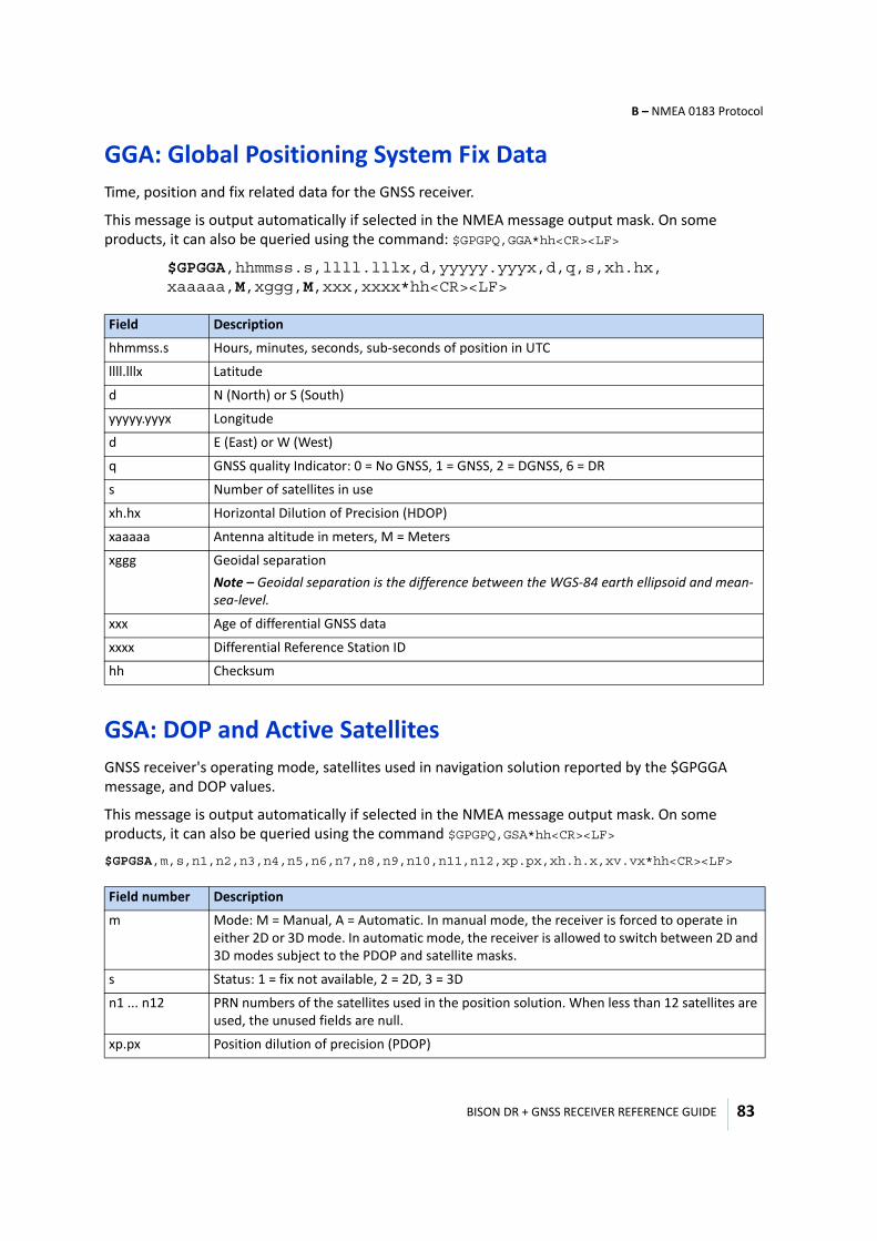
BISON DR + GNSS RECEIVER REFERENCE GUIDE
B – NMEA 0183 Protocol
83
GGA: Global Positioning System Fix Data Time, position and fix related data for the GNSS receiver.
This message is output automatically if selected in the NMEA message output mask. On some products, it can also be queried using the command: $GPGPQ,GGA*hh<CR><LF>
$GPGGA,hhmmss.s,llll.lllx,d,yyyyy.yyyx,d,q,s,xh.hx, xaaaaa,M,xggg,M,xxx,xxxx*hh<CR><LF>
GSA: DOP and Active Satellites GNSS receiver's operating mode, satellites used in navigation solution reported by the $GPGGA message, and DOP values.
This message is output automatically if selected in the NMEA message output mask. On some products, it can also be queried using the command $GPGPQ,GSA*hh<CR><LF>
$GPGSA,m,s,n1,n2,n3,n4,n5,n6,n7,n8,n9,n10,n11,n12,xp.px,xh.h.x,xv.vx*hh<CR><LF>
Field Description
hhmmss.s Hours, minutes, seconds, sub-seconds of position in UTC
llll.lllx Latitude
d N (North) or S (South)
yyyyy.yyyx Longitude
d E (East) or W (West)
q GNSS quality Indicator: 0 = No GNSS, 1 = GNSS, 2 = DGNSS, 6 = DR
s Number of satellites in use
xh.hx Horizontal Dilution of Precision (HDOP)
xaaaaa Antenna altitude in meters, M = Meters
xggg Geoidal separationNote – Geoidal separation is the difference between the WGS-84 earth ellipsoid and mean-sea-level.
xxx Age of differential GNSS data
xxxx Differential Reference Station ID
hh Checksum
Field number Description
m Mode: M = Manual, A = Automatic. In manual mode, the receiver is forced to operate in either 2D or 3D mode. In automatic mode, the receiver is allowed to switch between 2D and 3D modes subject to the PDOP and satellite masks.
s Status: 1 = fix not available, 2 = 2D, 3 = 3D
n1 ... n12 PRN numbers of the satellites used in the position solution. When less than 12 satellites are used, the unused fields are null.
xp.px Position dilution of precision (PDOP)
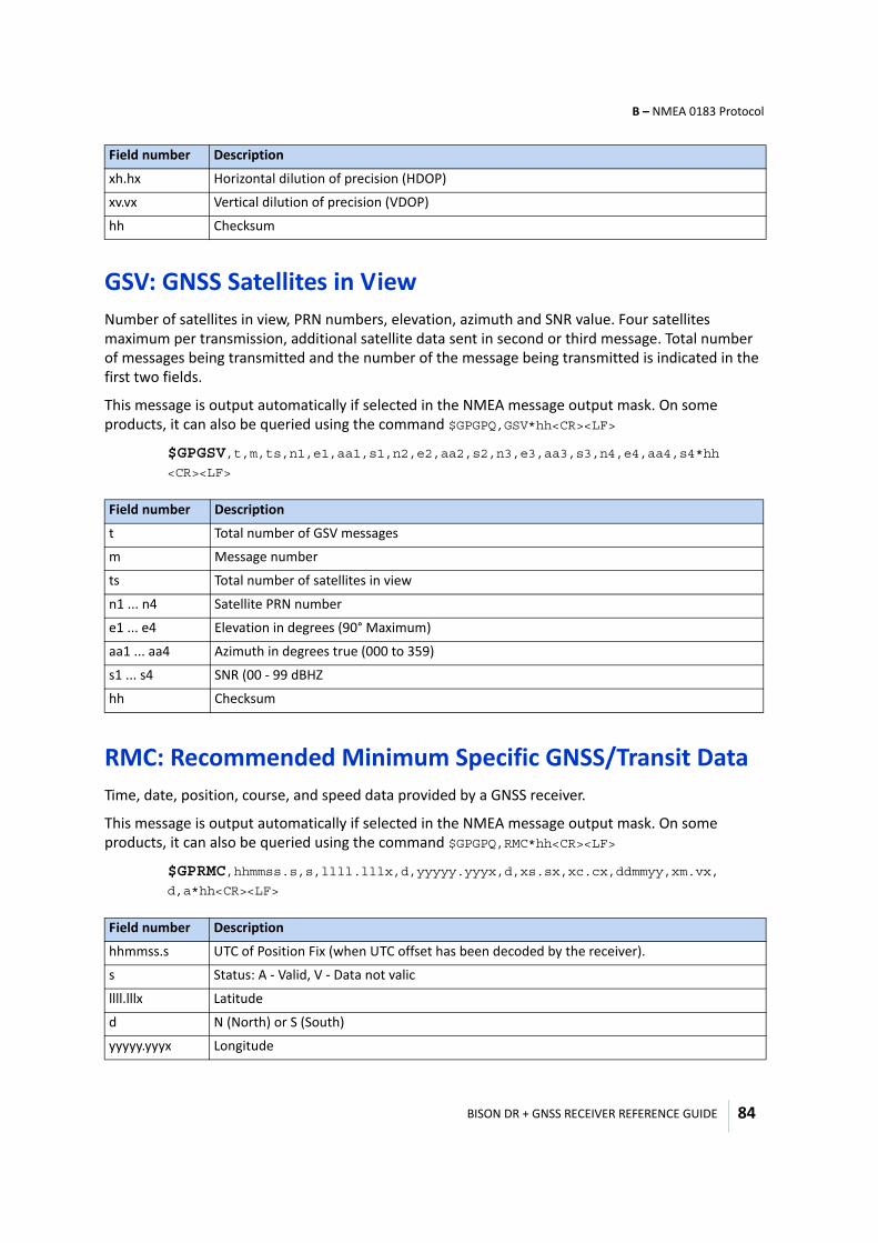
BISON DR + GNSS RECEIVER REFERENCE GUIDE
B – NMEA 0183 Protocol
84
GSV: GNSS Satellites in ViewNumber of satellites in view, PRN numbers, elevation, azimuth and SNR value. Four satellites maximum per transmission, additional satellite data sent in second or third message. Total number of messages being transmitted and the number of the message being transmitted is indicated in the first two fields.
This message is output automatically if selected in the NMEA message output mask. On some products, it can also be queried using the command $GPGPQ,GSV*hh<CR><LF>
$GPGSV,t,m,ts,n1,e1,aa1,s1,n2,e2,aa2,s2,n3,e3,aa3,s3,n4,e4,aa4,s4*hh <CR><LF>
RMC: Recommended Minimum Specific GNSS/Transit Data Time, date, position, course, and speed data provided by a GNSS receiver.
This message is output automatically if selected in the NMEA message output mask. On some products, it can also be queried using the command $GPGPQ,RMC*hh<CR><LF>
$GPRMC,hhmmss.s,s,llll.lllx,d,yyyyy.yyyx,d,xs.sx,xc.cx,ddmmyy,xm.vx, d,a*hh<CR><LF>
xh.hx Horizontal dilution of precision (HDOP)
xv.vx Vertical dilution of precision (VDOP)
hh Checksum
Field number Description
t Total number of GSV messages
m Message number
ts Total number of satellites in view
n1 ... n4 Satellite PRN number
e1 ... e4 Elevation in degrees (90° Maximum)
aa1 ... aa4 Azimuth in degrees true (000 to 359)
s1 ... s4 SNR (00 - 99 dBHZ
hh Checksum
Field number Description
hhmmss.s UTC of Position Fix (when UTC offset has been decoded by the receiver).
s Status: A - Valid, V - Data not valic
llll.lllx Latitude
d N (North) or S (South)
yyyyy.yyyx Longitude
Field number Description
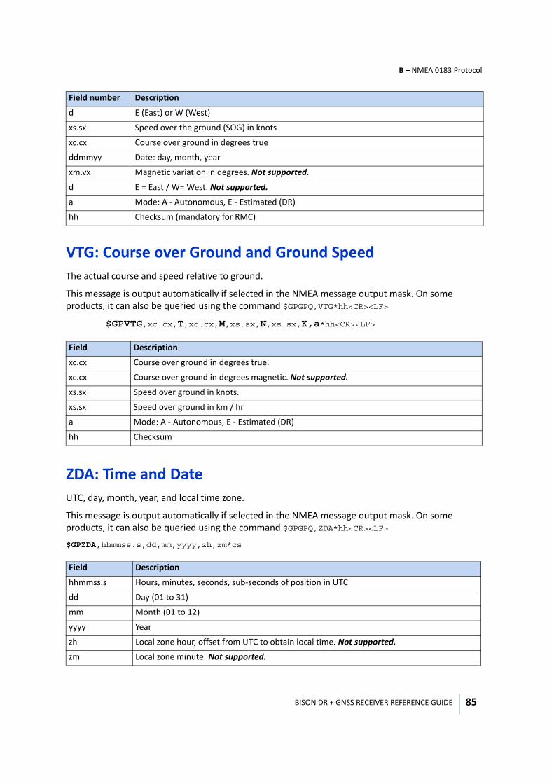
BISON DR + GNSS RECEIVER REFERENCE GUIDE
B – NMEA 0183 Protocol
85
VTG: Course over Ground and Ground SpeedThe actual course and speed relative to ground.
This message is output automatically if selected in the NMEA message output mask. On some products, it can also be queried using the command $GPGPQ,VTG*hh<CR><LF>
$GPVTG,xc.cx,T,xc.cx,M,xs.sx,N,xs.sx,K,a*hh<CR><LF>
ZDA: Time and DateUTC, day, month, year, and local time zone.
This message is output automatically if selected in the NMEA message output mask. On some products, it can also be queried using the command $GPGPQ,ZDA*hh<CR><LF>
$GPZDA,hhmmss.s,dd,mm,yyyy,zh,zm*cs
d E (East) or W (West)
xs.sx Speed over the ground (SOG) in knots
xc.cx Course over ground in degrees true
ddmmyy Date: day, month, year
xm.vx Magnetic variation in degrees. Not supported.
d E = East / W= West. Not supported.
a Mode: A - Autonomous, E - Estimated (DR)
hh Checksum (mandatory for RMC)
Field Description
xc.cx Course over ground in degrees true.
xc.cx Course over ground in degrees magnetic. Not supported.
xs.sx Speed over ground in knots.
xs.sx Speed over ground in km / hr
a Mode: A - Autonomous, E - Estimated (DR)
hh Checksum
Field Description
hhmmss.s Hours, minutes, seconds, sub-seconds of position in UTC
dd Day (01 to 31)
mm Month (01 to 12)
yyyy Year
zh Local zone hour, offset from UTC to obtain local time. Not supported.
zm Local zone minute. Not supported.
Field number Description
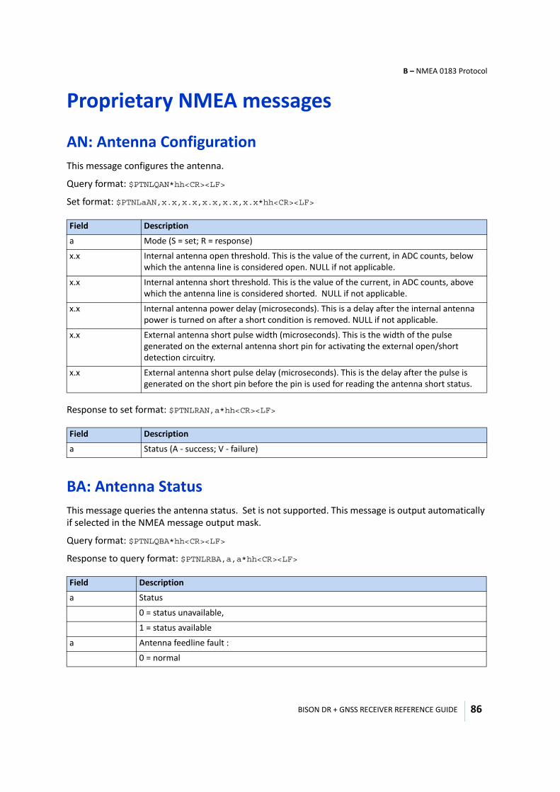
BISON DR + GNSS RECEIVER REFERENCE GUIDE
B – NMEA 0183 Protocol
86
Proprietary NMEA messages
AN: Antenna ConfigurationThis message configures the antenna.
Query format: $PTNLQAN*hh<CR><LF>
Set format: $PTNLaAN,x.x,x.x,x.x,x.x,x.x*hh<CR><LF>
Response to set format: $PTNLRAN,a*hh<CR><LF>
BA: Antenna StatusThis message queries the antenna status. Set is not supported. This message is output automatically if selected in the NMEA message output mask.
Query format: $PTNLQBA*hh<CR><LF>
Response to query format: $PTNLRBA,a,a*hh<CR><LF>
Field Description
a Mode (S = set; R = response)
x.x Internal antenna open threshold. This is the value of the current, in ADC counts, below which the antenna line is considered open. NULL if not applicable.
x.x Internal antenna short threshold. This is the value of the current, in ADC counts, above which the antenna line is considered shorted. NULL if not applicable.
x.x Internal antenna power delay (microseconds). This is a delay after the internal antenna power is turned on after a short condition is removed. NULL if not applicable.
x.x External antenna short pulse width (microseconds). This is the width of the pulse generated on the external antenna short pin for activating the external open/short detection circuitry.
x.x External antenna short pulse delay (microseconds). This is the delay after the pulse is generated on the short pin before the pin is used for reading the antenna short status.
Field Description
a Status (A - success; V - failure)
Field Description
a Status
0 = status unavailable,
1 = status available
a Antenna feedline fault :
0 = normal
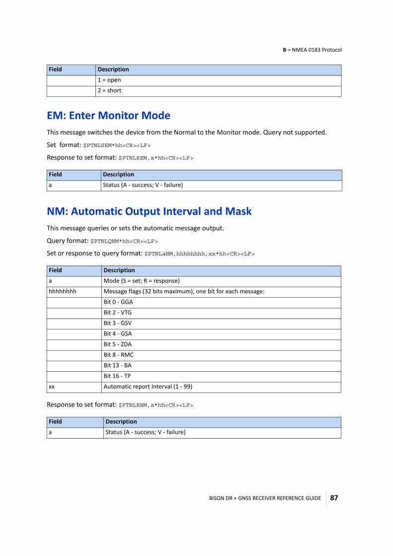
BISON DR + GNSS RECEIVER REFERENCE GUIDE
B – NMEA 0183 Protocol
87
EM: Enter Monitor ModeThis message switches the device from the Normal to the Monitor mode. Query not supported.
Set format: $PTNLSEM*hh<CR><LF>
Response to set format: $PTNLREM,a*hh<CR><LF>
NM: Automatic Output Interval and MaskThis message queries or sets the automatic message output.
Query format: $PTNLQNM*hh<CR><LF>
Set or response to query format: $PTNLaNM,hhhhhhhh,xx*hh<CR><LF>
Response to set format: $PTNLRNM,a*hh<CR><LF>
1 = open
2 = short
Field Description
a Status (A - success; V - failure)
Field Description
a Mode (S = set; R = response)
hhhhhhhh Message flags (32 bits maximum), one bit for each message:
Bit 0 - GGA
Bit 2 - VTG
Bit 3 - GSV
Bit 4 - GSA
Bit 5 - ZDA
Bit 8 - RMC
Bit 13 - BA
Bit 16 - TP
xx Automatic report Interval (1 - 99)
Field Description
a Status (A - success; V - failure)
Field Description
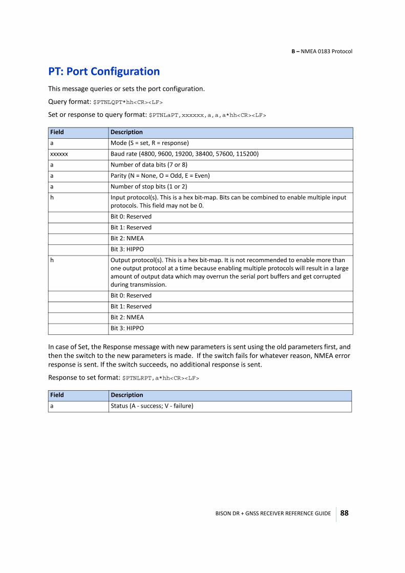
BISON DR + GNSS RECEIVER REFERENCE GUIDE
B – NMEA 0183 Protocol
88
PT: Port ConfigurationThis message queries or sets the port configuration.
Query format: $PTNLQPT*hh<CR><LF>
Set or response to query format: $PTNLaPT,xxxxxx,a,a,a*hh<CR><LF>
In case of Set, the Response message with new parameters is sent using the old parameters first, and then the switch to the new parameters is made. If the switch fails for whatever reason, NMEA error response is sent. If the switch succeeds, no additional response is sent.
Response to set format: $PTNLRPT,a*hh<CR><LF>
Field Description
a Mode (S = set, R = response)
xxxxxx Baud rate (4800, 9600, 19200, 38400, 57600, 115200)
a Number of data bits (7 or 8)
a Parity (N = None, O = Odd, E = Even)
a Number of stop bits (1 or 2)
h Input protocol(s). This is a hex bit-map. Bits can be combined to enable multiple input protocols. This field may not be 0.
Bit 0: Reserved
Bit 1: Reserved
Bit 2: NMEA
Bit 3: HIPPO
h Output protocol(s). This is a hex bit-map. It is not recommended to enable more than one output protocol at a time because enabling multiple protocols will result in a large amount of output data which may overrun the serial port buffers and get corrupted during transmission.
Bit 0: Reserved
Bit 1: Reserved
Bit 2: NMEA
Bit 3: HIPPO
Field Description
a Status (A - success; V - failure)
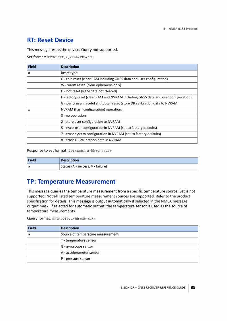
BISON DR + GNSS RECEIVER REFERENCE GUIDE
B – NMEA 0183 Protocol
89
RT: Reset DeviceThis message resets the device. Query not supported.
Set format: $PTNLSRT,a,x*hh<CR><LF>
Response to set format: $PTNLRRT,a*hh<CR><LF>
TP: Temperature MeasurementThis message queries the temperature measurement from a specific temperature source. Set is not supported. Not all listed temperature measurement sources are supported. Refer to the product specification for details. This message is output automatically if selected in the NMEA message output mask. If selected for automatic output, the temperature sensor is used as the source of temperature measurements.
Query format: $PTNLQTP,a*hh<CR><LF>
Field Description
a Reset type:
C - cold reset (clear RAM including GNSS data and user configuration)
W - warm reset (clear ephemeris only)
H - hot reset (RAM data not cleared)
F - factory reset (clear RAM and NVRAM including GNSS data and user configuration)
G - perform a graceful shutdown reset (store DR calibration data to NVRAM)
x NVRAM (flash configuration) operation:
0 - no operation
2 - store user configuration to NVRAM
5 - erase user configuration in NVRAM (set to factory defaults)
7 - erase system configuration in NVRAM (set to factory defaults)
8 - erase DR calibration data in NVRAM
Field Description
a Status (A - success; V - failure)
Field Description
a Source of temperature measurement:
T - temperature sensor
G - gyroscope sensor
A - accelerometer sensor
P - pressure sensor
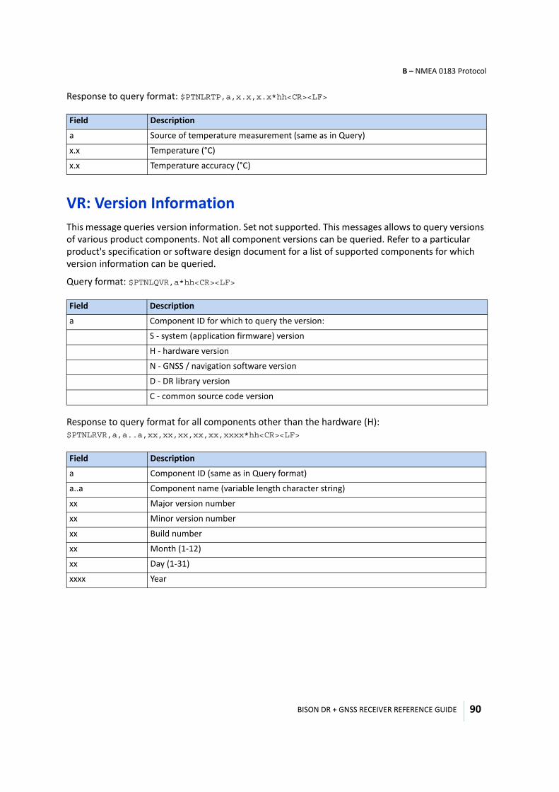
BISON DR + GNSS RECEIVER REFERENCE GUIDE
B – NMEA 0183 Protocol
90
Response to query format: $PTNLRTP,a,x.x,x.x*hh<CR><LF>
VR: Version InformationThis message queries version information. Set not supported. This messages allows to query versions of various product components. Not all component versions can be queried. Refer to a particular product's specification or software design document for a list of supported components for which version information can be queried.
Query format: $PTNLQVR,a*hh<CR><LF>
Response to query format for all components other than the hardware (H): $PTNLRVR,a,a..a,xx,xx,xx,xx,xx,xxxx*hh<CR><LF>
Field Description
a Source of temperature measurement (same as in Query)
x.x Temperature (°C)
x.x Temperature accuracy (°C)
Field Description
a Component ID for which to query the version:
S - system (application firmware) version
H - hardware version
N - GNSS / navigation software version
D - DR library version
C - common source code version
Field Description
a Component ID (same as in Query format)
a..a Component name (variable length character string)
xx Major version number
xx Minor version number
xx Build number
xx Month (1-12)
xx Day (1-31)
xxxx Year
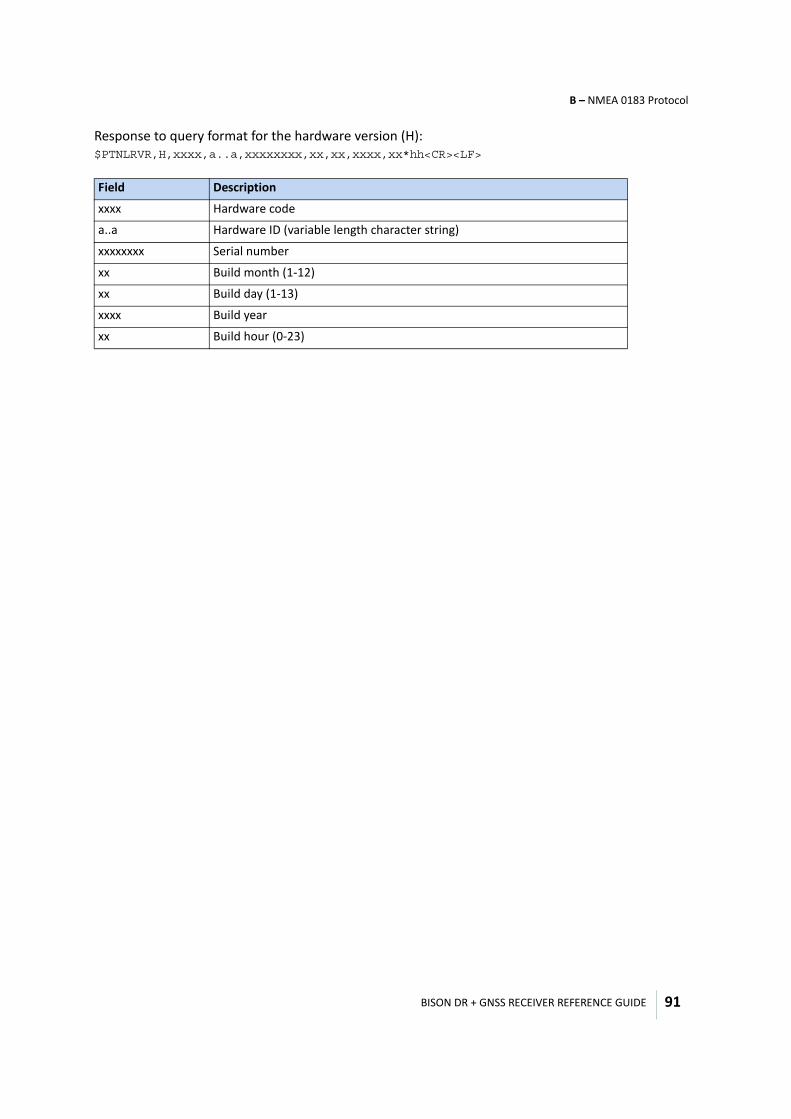
BISON DR + GNSS RECEIVER REFERENCE GUIDE
B – NMEA 0183 Protocol
91
Response to query format for the hardware version (H): $PTNLRVR,H,xxxx,a..a,xxxxxxxx,xx,xx,xxxx,xx*hh<CR><LF>
Field Description
xxxx Hardware code
a..a Hardware ID (variable length character string)
xxxxxxxx Serial number
xx Build month (1-12)
xx Build day (1-13)
xxxx Build year
xx Build hour (0-23)
C
BISON DR + GNSS RECEIVER REFERENCE GUIDE 92
A P P E N D I X
Reference Circuit C
In this appendix:
Bison reference circuit diagram
Circuits using externally powered antennas
This appendix provides a brief overview of the Bison module reference circuit diagram.
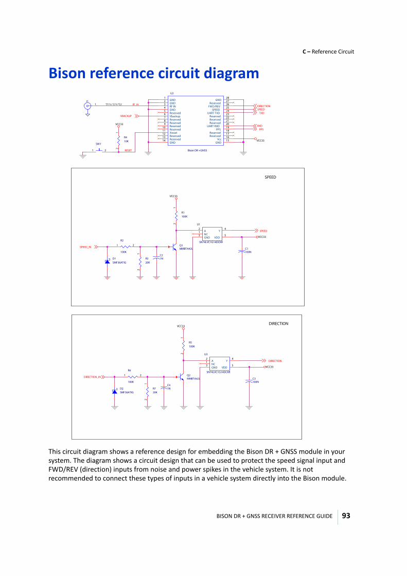
BISON DR + GNSS RECEIVER REFERENCE GUIDE
C – Reference Circuit
93
Bison reference circuit diagram
This circuit diagram shows a reference design for embedding the Bison DR + GNSS module in your system. The diagram shows a circuit design that can be used to protect the speed signal input and FWD/REV (direction) inputs from noise and power spikes in the vehicle system. It is not recommended to connect these types of inputs in a vehicle system directly into the Bison module.
RF_IN
RESET
VCC33
VCC33
VBACKUP
SPEEDDIRECTION
RXD
TXD
PPS
J11
R410K
12
SW1
1 2
U2
Bison DR +GNSS
GND1
GND2
RF IN3
GND4
Reserved5
Vbackup6
Reserved7
Reserved8
Reserved9
Reserved10
Xreset11
Reserved12
Reserved13
GND14
GND28
Reserved27
FWD/REV26
SPEED25
UART TXD24
Reserved23
Reserved22
Reserved21
UART RXD20
PPS19
Reserved18
Reserved17
Vcc16
GND15
DIRECTIONVCC33
VCC33
DIRECTION_IN
DIRECTION
R5100K
12
C3100N
R720K
12
C41N
U3
SN74LVC1G14DCKR
A2
NC1
GND3
Y4
VDD5
Q2MMBTA42L
D2SMF36ATIG
R6
100K
1 2
SPEED
VCC33
VCC33
SPEED_IN
SPEED
R320K
12
C21N
U1
SN74LVC1G14DCKR
A2
NC1
GND3
Y4
VDD5
Q1MMBTA42L
D1SMF36ATIG
R2
100K
1 2
R1100K
12
C1100N

BISON DR + GNSS RECEIVER REFERENCE GUIDE
C – Reference Circuit
94
Circuits using externally powered antennasThe following circuits show how to include antenna open and short detection on the Bison module when using an externally powered antenna. In this case, the internal open and short detection will not work since the Bison will supply no power to the antenna, so the internal current measurement will not reflect the actual power in the antenna. These sample circuits allow the Bison module to detect and report on open and shorted states of the antenna, even when the antenna is powered through an external source.
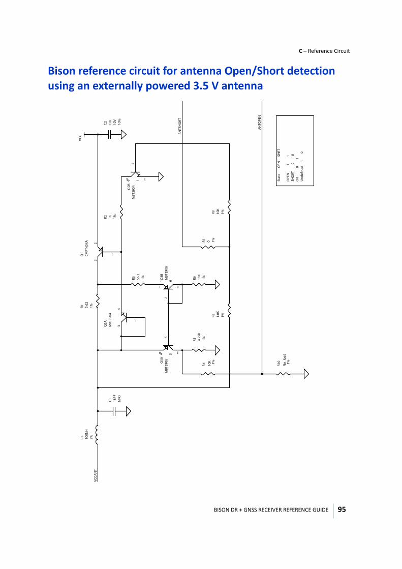
BISON DR + GNSS RECEIVER REFERENCE GUIDE
C – Reference Circuit
95
Bison reference circuit for antenna Open/Short detection using an externally powered 3.5 V antenna
R5 4.75
K1%
Q2A
MBT
3904
R10
No_
load
1%R4 10K 1%
L1 100N
H2%
Q1
CMPT
404A R7 0 1%
C1 18PF
NPO
Q2B
MBT
3904
R2 1K 1%
R6 10K
1%
R9 10K
1%
Q3A
MBT
3906
C2 1UF
10V
10%
R3 56.2
1%
R8 1.0K
1%
R1 5.62
1%
Q3B
MBT
3906
VCC
5
43
1
23
21
1
6
6
54
4
3
3
21
1
6
6
AN
TSH
ORT
AN
TOPE
N
VCCA
NT
Stat
e
O
PN
SH
RT O
PEN
1
1
SHO
RT
0
0
OK
0
1
Und
efine
d
1
0

BISON DR + GNSS RECEIVER REFERENCE GUIDE
C – Reference Circuit
96
VCC = 3.3 VCC = 5.0 1%, 125mW, resistorR1 5.62 ohms 10 ohms 1%, 62.5mW, resistorR2 1.0 K ohms 8.24 K ohms 1%, 125mW, resistorR3 56.2 ohms 56.2 ohms 1%, 62.5mW, resistorR4 10 K ohms 10 K ohms 1%, 62.5mW, resistorR5 4.75 K ohms 5.62 K ohms 1%, 62.5mW, resistorR6 10.0 K ohms 10.0 K ohms 1%, 62.5mW, resistorR7 0 ohms 0 ohms 1%, 62.5mW, resistorR8 1.0 K ohms 8.24 K ohms 1%, 62.5mW, resistorR9 10.0 K 10.0 K ohms 1%, 62.5mW, resistorR10 No_load No_load 1%, 62.5mW, resistorL1 100 nH 200 nH Inductor, 2%, 200 mA, wirewound, SRF = 1.8 GHzQ1 CMPT - 404A, PNP Ic = 150mA, hfe = 100 min, Vce = 35 V (Central Semiconductor)Q2 DMMT3904 W, Dual transistor matched pair (Diodes Inc)Q3 DMMT3906 W, Dual transistor matched pair (Diodes Inc)C1 18PF, 5%, NPO, Ceramic Capacitor, 25 voltsC2 1UF, 10%, X7R, Ceramic Capacitor, 10 volts