Embed Size (px)
Citation preview

Research ArticleBedding Plane Effects on Mechanical Behavior of SurroundingRock in Mountain Tunneling
Shuang You 12 Jincui Sun 1 and Hongtao Wang1
1School of Civil and Resource Engineering University of Science and Technology Beijing Beijing 100083 China2Beijing Key Laboratory of Urban Underground Space Engineering University of Science and Technology BeijingBeijing 100083 China
Correspondence should be addressed to Jincui Sun sunjincui0922163com
Received 29 July 2021 Revised 23 August 2021 Accepted 24 September 2021 Published 13 October 2021
Academic Editor Fan Feng
Copyright copy 2021 Shuang You et al )is is an open access article distributed under the Creative Commons Attribution Licensewhich permits unrestricted use distribution and reproduction in any medium provided the original work is properly cited
)e layered rock showed the characteristics inMountain tunnel Yunnan A series of uniaxial compression tests and variable angleshear tests were carried out and the aim was to investigate the effect of the bedding on its mechanical parameters and failuremodes )e test results show that the uniaxial compressive strength elastic modulus and Poissonrsquos ratio of layered rock present aU-shaped distribution with the increase in bedding orientation from 0deg to 90deg All of them have a maximum when the beddingorientation is 0deg and a minimum when the bedding orientation is 45deg )e failure modes of layered rock can be summarized intothree types the fracture tensile failure parallel to the weak plane of bedding the shear slip failure along bedding weak plane andtension-shear composite failure between bedding weak plane and matrix Based on the testing data and analysis results it can beconcluded that the layered rock specimen with different bedding orientations is an important reason for the anisotropy ofmechanical parameters and failure modes
1 Introduction
)e layered rock is usually interbedded with soft and hardrock )e main structural plane is bedding plane and thereare weak structural planes such as interlayer dislocation andargillaceous intercalation )e deformation and failure aremainly controlled by geology and rock combination )eheterogeneity of the rock with bedding plane is enhancedand the minerals on the internal plane are easy to form weakstructural plane When there is bedding plane in the rockmass it makes the axial strain larger In the construction oftunnels in layered rock the anisotropy of surrounding rockis very important to the safety and stability [1 2] Whendrilling in layered rock formation the permeability offractures between bedding is much higher than that of rockmatrix Fluid is easy to immerse into the formation along themicrofractures between bedding which changes the effectivestress state around the well reducing the strength of layeredrock and affecting the stability of wellbore during drilling[3] )erefore it is of great engineering application value to
study that bedding orientation effects on mechanical pa-rameters and failure mode of layered rock
At present many scholars have obtained lots ofachievements in the study of the effect of bedding orien-tation on layered rock Wang et al [4] conducted Braziliansplitting tests on slates with different bedding orientationsand clarified the failure mechanism by analyzing the changesof tensile strength and failure behavior Yang et al [5]carried out the direct shear test on layered rock specimensand the results show that the bedding orientation has asignificant effect on the cohesion and internal friction angleof rock Xia et al [6] carried out the direct shear test oflayered rock and the results show that with the increase inthe bedding orientation the shear strength index of rockmass first increases then decreases and finally increases Fanet al [7] used theoretical analysis and numerical simulationto study the macroscopic mechanical behavior of layeredrock and discussed transversely the isotropy strength cri-terion of layered rock Li et al [8] without considering theinfluence of c and φ when the bedding orientation of layered
HindawiShock and VibrationVolume 2021 Article ID 7346061 10 pageshttpsdoiorg10115520217346061
rock is 45deg the crack initiation and propagation are mostlikely to occur when β is known the corresponding fracturetoughness value can be obtained Liu et al [9] conducteduniaxial compression tests to show that there are two formsof compression failure of layered rock compression shearfailure occurs from the interior of layered rock and the shearplane is rough the surface of layered rock is smooth andsliding failure occurs along the bedding plane Gao et al [10]conducted compressive and tensile strength tests of shaleand analyzed the transversely isotropy characteristics ofshale specimens )e results show that the tensile strengthperpendicular to the bedding plane is about 300ndash360 timesthat parallel to the bedding plane and the velocity anisot-ropy ratio of compression wave is about 13-14 Liu et al[11] obtained three failure mechanisms of layered rocktensile failure along bedding plane shear failure alongbedding plane and tensile failure of matrix in the directtensile test)rough numerical simulation Tan et al [12 13]analyzed the stability of layered rock with different beddingdirections the range of surrounding rock loose area and thekey parts of instability which has important theoreticalsignificance for further understanding the instabilitymechanism of tunnel in layered rock Xia et al [14] carriedout numerical simulation of rock with different beddingorientations under the uniaxial compression test and ob-tained that when the bedding bond strength is very differentfrom the bedrock the effect of bedding can be ignored whilewhen the two are close bedding has a great influence Fuet al [15] conducted the uniaxial compression test on layeredrock and obtained that there are three failure forms of rockmass with the change of bedding orientation Yuan et al [16]studied the influence of loading rate on the mechanicalproperties of layered rock and obtained that the total energyelastic strain energy and dissipated energy of rockmass afterexceeding the critical value of loading rate have S-shapedcurve variation law similar to the strength
In this paper the transverse isotropy and anisotropy oflayered rocks in Mountain tunnel Yunnan were studied)rough the uniaxial compression test and variable angleshear test the variation law of peak strength and mechanicalparameters of layered rocks with different bedding orien-tations was explored and the failure modes were classifiedand analyzed When layered rocks were treated as trans-versely isotropic bodies five independent material param-eters were determined )e relationship among beddingorientation cohesion and internal friction angle wasestablished
2 Calculation Principle of TransverselyIsotropic Constitutive Model Parameters
)e physical parameters mechanical parameters and hy-draulic parameters of rock mass usually show anisotropyand these parameters will change with the change of di-rection Although layered rock shows different mechanicalproperties at different bedding orientations it is usuallyregarded as transversely isotropic in practical engineeringapplications As shown in Figure 1 the coordinate system XY and Z is set where the Z axis is the longitudinal axis
direction of the specimen In the general coordinate systemthe stress-strain relationship is as follows [17]
ε Sσ (1)
where ε is the strain tensor S is the flexibility matrix and σ isthe stress tensor )e matrix is expressed as follows
εx
εy
εz
yxy
yyz
yzx
⎡⎢⎢⎢⎢⎢⎢⎢⎢⎢⎢⎢⎢⎢⎢⎢⎢⎢⎢⎢⎢⎢⎢⎢⎢⎢⎢⎢⎢⎢⎢⎢⎢⎢⎢⎢⎢⎢⎢⎢⎢⎢⎢⎢⎢⎢⎢⎢⎢⎢⎢⎢⎢⎢⎢⎢⎢⎢⎢⎢⎢⎢⎢⎢⎢⎢⎢⎢⎢⎢⎢⎢⎢⎢⎢⎢⎢⎢⎢⎢⎢⎢⎢⎢⎢⎢⎢⎢⎢⎣
⎤⎥⎥⎥⎥⎥⎥⎥⎥⎥⎥⎥⎥⎥⎥⎥⎥⎥⎥⎥⎥⎥⎥⎥⎥⎥⎥⎥⎥⎥⎥⎥⎥⎥⎥⎥⎥⎥⎥⎥⎥⎥⎥⎥⎥⎥⎥⎥⎥⎥⎥⎥⎥⎥⎥⎥⎥⎥⎥⎥⎥⎥⎥⎥⎥⎥⎥⎥⎥⎥⎥⎥⎥⎥⎥⎥⎥⎥⎥⎥⎥⎥⎥⎥⎥⎥⎥⎥⎥⎦
1E1
minusv1
E1minus
v2
E2
minusv1
E1
1E1
minusv2
E2
minusv2
E2minus
v2
E2
1E2
0
0
2 1 + v1( 1113857
E1
1G12
1G12
⎡⎢⎢⎢⎢⎢⎢⎢⎢⎢⎢⎢⎢⎢⎢⎢⎢⎢⎢⎢⎢⎢⎢⎢⎢⎢⎢⎢⎢⎢⎢⎢⎢⎢⎢⎢⎢⎢⎢⎢⎢⎢⎢⎢⎢⎢⎢⎢⎢⎢⎢⎢⎢⎢⎢⎢⎢⎢⎢⎢⎢⎢⎢⎢⎢⎢⎢⎢⎢⎢⎢⎢⎢⎢⎢⎢⎢⎢⎢⎢⎢⎢⎢⎢⎢⎢⎢⎢⎢⎢⎢⎢⎢⎢⎢⎢⎢⎢⎢⎢⎢⎢⎢⎢⎢⎢⎢⎢⎢⎢⎢⎢⎢⎢⎢⎢⎢⎢⎢⎢⎢⎢⎢⎢⎢⎢⎢⎢⎢⎢⎢⎢⎢⎢⎢⎢⎢⎢⎢⎢⎢⎢⎢⎢⎢⎢⎢⎢⎢⎢⎢⎢⎢⎢⎢⎢⎢⎢⎢⎢⎢⎢⎢⎢⎢⎢⎢⎢⎢⎢⎢⎢⎢⎢⎢⎢⎢⎢⎢⎢⎢⎢⎢⎢⎢⎢⎢⎢⎢⎢⎢⎢⎢⎢⎢⎢⎢⎢⎢⎢⎢⎢⎢⎢⎢⎢⎢⎢⎢⎣
⎤⎥⎥⎥⎥⎥⎥⎥⎥⎥⎥⎥⎥⎥⎥⎥⎥⎥⎥⎥⎥⎥⎥⎥⎥⎥⎥⎥⎥⎥⎥⎥⎥⎥⎥⎥⎥⎥⎥⎥⎥⎥⎥⎥⎥⎥⎥⎥⎥⎥⎥⎥⎥⎥⎥⎥⎥⎥⎥⎥⎥⎥⎥⎥⎥⎥⎥⎥⎥⎥⎥⎥⎥⎥⎥⎥⎥⎥⎥⎥⎥⎥⎥⎥⎥⎥⎥⎥⎥⎥⎥⎥⎥⎥⎥⎥⎥⎥⎥⎥⎥⎥⎥⎥⎥⎥⎥⎥⎥⎥⎥⎥⎥⎥⎥⎥⎥⎥⎥⎥⎥⎥⎥⎥⎥⎥⎥⎥⎥⎥⎥⎥⎥⎥⎥⎥⎥⎥⎥⎥⎥⎥⎥⎥⎥⎥⎥⎥⎥⎥⎥⎥⎥⎥⎥⎥⎥⎥⎥⎥⎥⎥⎥⎥⎥⎥⎥⎥⎥⎥⎥⎥⎥⎥⎥⎥⎥⎥⎥⎥⎥⎥⎥⎥⎥⎥⎥⎥⎥⎥⎥⎥⎥⎥⎥⎥⎥⎥⎥⎥⎥⎥⎥⎥⎥⎥⎥⎥⎥⎦
(2)
In equation (2) there are five independent elastic pa-rameters namely E1 E2 v1 v2 and G12 which togetherrepresent the deformation performance E1 and E2 are theelastic modulus in the transversely isotropic plane and thedirection perpendicular to the plane respectively Poissonrsquosratios v1 and v2 describe the reflection of the transversestrain in the transversely isotropic plane and the stressparallel or perpendicular to the isotropic plane respectivelyG12 is the shear modulus perpendicular to the transverselyisotropic plane
In this experiment v1 and v2 are Poissonrsquos ratio when thebedding orientation is 90deg and 0deg respectively In order todetermine these five independent material parameters atleast one specimen with any bedding orientation is needed in
Z
YO
X
Figure 1 Schematic diagram of transversely isotropic material inthe global coordinate system
2 Shock and Vibration
addition to the specimens with 0deg and 90deg bedding orien-tation )erefore the sample with 30deg bedding orientation isselected )e formula of the elastic modulus with β betweenloading direction and bedding plane is as follows [17]
1Eβ
sin4 β
E1+
1G12
minus2]1E1
1113888 1113889sin2 β cos2 β +cos4 β
E2 (3)
where Eβ is the elastic modulus when the angle betweenloading direction and bedding plane is β
3 Experimental Tests
31 Specimen Preparation )e rock core used in the test istaken from the tunnel of Xiangli Expressway Tunnel inYunnan Province )e structural characteristics of the rockmass are plate-shaped or flaky-shaped)ere is a small amountof clay and silty filler in the rock fracture (as shown in Fig-ure 2) )e specimens were taken from the whole large rockmass and cut into the whole cube In order to study the an-isotropic characteristics of rock mass under different beddingorientations core drilling sampling was carried out from fivedirections of 0deg 30deg 45deg 60deg and 90deg respectively )e sche-matic diagram of core drilling sampling is shown in Figure 3
According to the specific requirements the specimensused in the test were processed into test blocks of differentsizes and shapes by drilling and grinding machines )enumber of test blocks in each group should not be less than3 )e standard specimens were made as followsΦ25times 50mm cylinder specimens were used for the uniaxialcompression test (as shown in Figure 4) and cube specimenswith 30mm side length were used for the variable angleshear test (as shown in Figure 5)
32 Test Equipment and Scheme )e uniaxial compressiontest and variable angle shear test were carried out on cylinderspecimens and cube specimens respectively GAW-2000electrohydraulic servocontrolled uniaxial test machine andhydraulic screen display universal testing machine (a set of20deg 30deg and 40deg variable angle shear fixture) are used andthese equipments have stable performance and high testaccuracy In the uniaxial compression test the displacementcontrol mode was adopted and the axial load was applied tothe specimens at the loading speed of 0015mmmin and thestress-strain curve was collected at the same time In thevariable angle shear test the stress control method was usedto apply the load at the loading rate of 100Ns until thespecimens failed and the failure load P was recorded asshown in Figure 6
4 Analysis of Test Results
41 Influence of Bedding Structure on Rock MechanicalParameters )e results of uniaxial compression tests oflayered rock with different bedding orientations are shownin Figure 7
It can be seen from Figure 7(a) that when the beddingorientation changes from 0deg to 90deg the peak strength oflayered rock first decreases and then increases )e peak
strength decreases between 0deg and 45deg and increases between45deg and 90deg On the whole there is a ldquoU-shapedrdquo changetrend of high on both sides and low in the middle )e peakstrength is the highest at 0deg and the lowest at 45deg )e resultsare consistent with the previous layered rock test results[18ndash20] )e maximum peak strength is more than threetimes of the minimum peak strength )erefore the peakstrength of layered rock is affected by bedding orientationshowing obvious anisotropy characteristics
According to the concept of ldquoanisotropy ratiordquo proposedby J Singh et al [21] in 1989 the anisotropy ratio of peakstrength of layered rock is defined as follows
Rc σcmax
σcmin (4)
where Rc is the anisotropy ratio of peak strength σcmax is themaximum peak strength and σcmin is the minimum peakstrength According to Figure 3 when the bedding orientationis 0deg the peak strength is themaximum (9490MPa) andwhenthe bedding angle is 45deg the peak strength is the minimum(2726MPa) that is Rc is 348 so the anisotropy ratio of thepeak strength of layered rock is medium anisotropy
According to the test results and equation (3) five in-dependent parameters of layered rock can be obtained asshown in Table 1
After the transverse isotropy material parameters oflayered rock are determined more accurate engineeringanalysis can be carried out for the rock engineering withlayered rock as the main lithologic characteristics such asthe change of rock stress state and the deformation of rockmass caused by tunnel excavation in layered rock stratum
42 Influence of Bedding Structure on Rock FractureCharacteristics )e anisotropy of mechanical parameters oflayered rock is closely related to its fracture mode With thechange of bedding orientation the fracture of specimensshows different failure modes In the uniaxial compressiontest the specimen is subjected to load and goes throughcompaction stage elastic stage expansion stage and failurestage When the axial stress reaches the specimen peakstrength the accumulated energy inside the specimen isreleased suddenly and the failure occurs Obvious macro-cracks appear on the surface and run through the whole
Figure 2 Bedding structure of surrounding rock of Xiangli Ex-pressway Tunnel in Yunnan Province
Shock and Vibration 3
0deg 30deg45deg
60deg
90deg
(a)
0deg30deg
60deg
90deg
(b)
Figure 3 Schematic diagram of core sampling (a) bedding orientations of the cylinder specimen (b) bedding orientations of the cubespecimen
Figure 4 Cylinder specimens
Figure 5 Cube specimens
(a) (b)
Figure 6 Diagram of test procedure (a) uniaxial compression test process (b) variable angle shear test process
4 Shock and Vibration
specimen forming multiple tensile and shear failure sur-faces )e failure mode has obvious anisotropy )e failuremodes of specimens with different bedding orientations areshown in Figure 8
In general the failure phenomena of all rock specimenshave the characteristics of tension failure and shear failurebut the failure modes of rock specimens with differentbedding orientations are different
0102030405060708090
100
Peak
stre
ngth
MPa
Peak strength
0
30
60
90
270
120
150
180
210
240 300
330
(a)
0
30
60
90
270
120
150
180
210
240 300
330
02468
10121416
Elas
tic m
odul
us G
Pa
Elastic modulus
(b)
0
30
60
90
270
120
150
180
210
240 300
330
000
002
004
006
008
010
012
Poiss
ons
ratio
Poissons ratio
(c)
Figure 7 Mechanical parameters of layered rock with different bedding orientations (a) peak strength of layered rock (b) elastic modulusof layered rock (c) Poissonrsquos ratio of layered rock
Table 1 Independent parameters of layered rock
E1 (GPa) E2 (GPa) v1 v2 G12 (GPa)
933 1453 0081 0100 4019
Shock and Vibration 5
(1) β 0deg Shear slip failure is the main failure form Forthe specimens with 0deg bedding orientation thecrack direction is almost horizontal only a fewsplitting cracks appear at the end of the specimen)e reason is that the loading direction is or-thogonal to the bedding orientation and the twoends of the specimen are subject to friction resis-tance which limits its lateral deformation )etensile failure through the weak plane of the bed-ding is formed in the middle of the specimen underthe action of large lateral tension which leads to theobvious shear slip phenomenon of the upper andlower parts of the specimen along the directionapproximately parallel to the weak plane of thebedding and causes the local surface fracture of thespecimen Under the action of large lateral tensionin the middle of the specimen the tensile failurethrough the weak plane of the bedding is formedwhich leads to the obvious shear slip phenomenonof the upper and lower parts of the specimen
(2) β 30deg Tension and shear failure coexist Underthe action of external load cracks develop alongthe weak plane of bedding until the specimen isdestroyed Under the action of load the crackdevelops along the weak plane of beddingforming a shear failure plane through the weakplane of bedding At the same time a tensilefailure plane is formed along the weak plane ofbedding on the surface of specimen leading tolocal fracture )e crack develops along the axialdirection which is similar to the weak plane ofbedding
(3) β 45deg Tension-shear composite failure betweenbedding weak plane and matrix Under the action ofload two large angle shear cracks are formed on bothsides of the specimen surface which are differentfrom the bedding orientation During the loadingprocess the cracks gradually expand and finally forma tensile-shear composite failure plane along the
bedding weak plane and through the weak plane ofbedding and matrix )e failure plane runs throughthe two weak planes of bedding and intersects in themiddle of the specimen It shows multiple shearfailure surfaces similar to Y shape
(4) β 60deg Shear failure is significant and cracks al-most all develop along the bedding orientationUnder the action of load obvious shear failure isformed along the bedding weak plane at the upperand lower ends of the specimen and many flatfailure planes are formed at the upper and lowerends of the specimen and the shear slip phe-nomenon parallel to the bedding weak plane occurs)is is because the shear stress on the bedding weakplane is greater than the shear strength of thespecimen itself
(5) β 90deg Tension and shear failure coexist but ten-sion failure is the main failure form )e crack has asmall vertical inclination and through the entirerock specimen Under the action of load thespecimen gradually appears tensile cracks parallelto the bedding plane and finally forms the splittingtension failure along the bedding plane )e spec-imen has a tensile fracture plane which is obviouslyparallel to the bedding weak plane and runs throughthe matrix and through the ends of the entire rockspecimen Since the entire specimen is divided intotwo parts one large and one small their bearingcapacity is reduced respectively )e smaller part ofthe thin slab-shaped rock bears greater load than itsown compressive strength It leads to bucklinginstability and secondary rupture along the beddingweak plane
From the above analysis the main controlling factors oflayered rock fracture with different bedding orientations canbe obtained It can be seen from the analysis that for any rockspecimen failure mechanism with different bedding orien-tations the bedding weak plane plays a leading role)erefore the bedding weak plane has become a key factor
(a) (b) (c) (d) (e)
Figure 8 Uniaxial compression failure diagram of rock specimen (a) β 0deg (b) β 30deg (c) β 45deg (d) β 60deg (e) β 90deg
6 Shock and Vibration
affecting the anisotropy of the failure mechanism of layeredrock specimens
)e elastic modulus is an important performanceparameter of engineering materials From the macro-scopic point of view the elastic modulus is a measure ofthe ability of an object to resist elastic deformation )eelastic modulus of the material can be affected by all thefactors that affect the bonding strength When there isbedding plane in the rock the bedding plane belongs tothe weak plane of the rock so compared with the matrixmaterial the stiffness of the weak plane of bedding is smalland the deformation is large Compared with the rockmass without bedding plane this kind of rock is prone tofailure under uniaxial compression
)e variation of elastic modulus and Poissonrsquos ratio withbedding orientation is shown in Figures 7(b) and 7(c) It canbe seen from Figure 7(b) that under the uniaxial com-pression test of layered rock the elastic modulus first de-creases and then increases with the increase in the anglebetween bedding orientation and horizontal plane On thewhole it is similar to the change trend of compressivestrength and also presents a U-shaped change trend of highon both sides and low in the middle When the beddingorientation is 0deg (parallel to the bedding) the elastic modulusof layered rock is the largest when the bedding orientation is45deg the elastic modulus of layered rock is the smallest )evertical bedding is easy to be tensioned and split along thebedding plane under the action of axial stress in parallelbedding because the axial stress is perpendicular to thebedding plane the stacking reaction occurs on the beddingplane during loading resulting in the compression of thebedding plane and the axial strain changes relatively large)e deformation modulus is used to define the anisotropyratio of layered rock
RE Emax
Emin (5)
where RE is the anisotropy ratio of the elastic modulus Emaxis the maximum elastic modulus of layered rock between 0degand 90deg bedding orientation and Emin is the minimumelastic modulus of layered rock between 0deg and 90deg beddingorientation )e ratio of the maximum to the minimum is
28 which is the anisotropy ratio of the deformationmodulus of layered rock
Poissonrsquos ratio of layered rock specimens as shown inFigure 7(c) is similar to the compressive strength andelastic modulus of layered rock It shows a U-shapedchange trend of high on both sides and low in the middleOn the whole Poissonrsquos ratio decreases or increases but theamplitude is small at the low bedding orientation (from 0degto 30deg) and the high bedding orientation (from 60deg to 90deg)which indicates that the bedding anisotropy is weak at thistime at the slightly higher bedding orientation (from 30deg to60deg) Poissonrsquos ratio changes greatly with the beddingorientation which indicates that the bedding anisotropy isstrong at this time
43 Effect of Bedding Plane on Rock Shear Properties )eresults of the variable angle shear test of layered rock areshown in Table 2
According to the measured data of normal stress andshear stress in Table 2 the fitting results are shown inFigure 9
It can be seen from Figure 9 that the overall fitting degreeof the MohrndashCoulomb fitting curve is very high Accordingto Figure 9 the cohesion and internal friction angles withdifferent bedding orientations can be obtained and theresults are shown in Table 3
According to the above the cohesion and internal frictionangle with different bedding orientations are obtained andthe relationship among bedding orientation cohesion andinternal friction angle is established as shown in Figure 10
It can be seen from Figure 10 that with the increase in theangle between bedding plane and horizontal plane thecohesion and internal friction angle of layered rock speci-mens first decrease and then increase showing a U-shapedvariation trend of high at both sides and low in the middlesimilar to the compressive strength curveWhen the beddingorientation is 0deg and 90deg the cohesion and internal frictionangle are relatively large and when the bedding orientationis 60deg they are relatively small
)e failure modes are shown in Figure 11 When thebedding orientation is 0deg there is the composite failure oftension through weak bedding plane and shear slip along
Table 2 Test results of variable angle shear of layered rock
Bedding orientation (deg) Failure load (kN) Shear stress τ (MPa) Normal stress σ (MPa) Fixture angle (deg)
06587 2503 6878 202542 1412 2446 301536 1097 1307 40
304567 1736 4768 202122 1179 2042 301368 977 1164 40
603269 1242 3413 201412 784 1359 301224 874 1042 40
907937 3016 8324 202791 1551 784 301982 1416 1687 40
Shock and Vibration 7
bedding plane when the bedding orientation is 30deg the shearfailure along the weak bedding plane and through thebedding plane occurs when the bedding orientation is 60degthe shear slip failure along the weak bedding plane occurs
and the ends present the phenomenon of crossing thematrix when the bedding orientation is 90deg the splittingtensile failure along the weak bedding plane occurs and thefailure surface is relatively regular
5
10
15
20
25
30
35
Shea
r str
essM
Pa
10 20 30 40 50 60 70 80 900Normal stress MPa
0deg bedding30deg bedding60deg bedding90deg bedding
0deg bedding fitting curve30deg bedding fitting curve60deg bedding fitting curve90deg bedding fitting curve
Figure 9 MohrndashCoulomb curves of shear strength of layered rocks under different loading modes
Table 3 Cohesion and internal friction angle with different bedding orientations
Bedding orientation (deg) Fitting curve Cohesion (MPa) Internal friction angle (deg)0 τ 025σ + 782 782 140730 τ 020σ + 742 742 118060 τ 018σ + 619 619 101890 τ 025σ + 943 943 1398
0 30Bedding angle deg
60 905
6
7
8
9
10
Cohe
sion
MPa
0
3
6
9
12
15
Inte
rnal
fric
tion
angl
e deg
CohesionInternal friction angle
Figure 10 Variation of cohesion and internal friction angle with bedding orientation
8 Shock and Vibration
5 Conclusions
In this paper uniaxial compression and variable angle sheartests are carried out on rocks with different bedding ori-entations By analyzing the evolution trend of mechanicalparameters and failure modes of with different beddingorientations the following conclusions are drawn
(1) )e compressive strength of layered rock has obviousanisotropy With the increase in the angle betweenbedding orientation and horizontal plane the uni-axial compressive strength first decreases and thenincreases and generally presents a U-shaped varia-tion trend of high on both sides and low in themiddle RC 48 indicating that the specimen ismoderately transverse isotropic
(2) )e elastic modulus and Poissonrsquos ratio of layeredrock first decrease and then increase with the in-crease in the bedding orientation On the whole thevariation trend of both is similar to the compressivestrength of layered rock
(3) In the uniaxial compression test of layered rock theanisotropy of failure mechanism of layered rock isclosely related to the bedding orientations which ismainly reflected in different failure modes withdifferent bedding orientations On the whole thefailure modes of Figure 1specimens can be dividedinto three types the fracture tensile failure parallelto the weak plane of bedding the shear slip failurealong bedding weak plane and tension-shearcomposite failure between bedding weak plane andmatrix
(4) )e cohesion and internal friction angle of layeredrock specimens show a U-shaped change trend ofhigh at both sides and low in the middle similar tothe compressive strength curve For the variableangle shear test the 0deg specimen shows the compositefailure of tension through the bedding weak planeand shear slip along the bedding plane Shear failurealong bedding plane and through bedding planeoccurs in the 30deg specimen )e shear slip failure
along the bedding plane occurs in the 60deg specimenand the end of the specimen runs through thematrix)e 90deg specimen shows splitting tensile failure alongthe bedding weak plane
Data Availability
)e data used to support the findings of this study areavailable from the corresponding author upon request
Conflicts of Interest
)e authors declare that there are no conflicts of interestregarding the publication of this paper
Acknowledgments
)e authors would like to thank for funds from the NationalNatural Science Foundation of China (51774021 and52074021) and the Key Research Development Program ofShandong Province China (2019SDZY05)
References
[1] E Q Li H C Zhang L F Zhang T Y Zhu J G Lu andJ L Feng ldquoBrazilian splitting test and numerical study ofcarbonaceous plate with different bedding diprdquo Rock and SoilMechanics vol 41 no 9 pp 2869ndash2879 2020
[2] Z X Luo W W Peng Y Y Wei D Q Hou and Y YangldquoExperimental study onmechanical properties of rockmass inunderground powerhouse of Lianghekou Hydropower Sta-tionrdquo Chinese Journal of Underground Space and Engineeringvol 13 no S2 pp 565ndash570 2017
[3] C C Wang J T Li H Lin J Liao P X Wang andS Q Wang ldquoMechanical characteristics of uniaxial com-pression anisotropy of platerdquo Journal of Central South Uni-versity vol 47 no 11 pp 3759ndash3764 2016
[4] H Wang F Ren and Y Chang ldquoEffect of bedding angle ontunnel slate failure behavior under indirect tensionrdquo Geo-matics Natural Hazards and Risk vol 11 no 1 pp 428ndash4452020
[5] Y D Yang F F Jia B Liang D Xia and C S Wu ldquoEx-perimental study on the influence of bedding dip angle on
(a) (b)
(c) (d)
Figure 11 Variable angle shear failure diagram with different bedding orientations (a) β 0deg (b) β 30deg (c) β 60deg (d) β 90deg
Shock and Vibration 9
rock shear strength parametersrdquo Mining Technology vol 19no 6 pp 77ndash81 2019
[6] L Xia J S Yao and L Jiang ldquoEffect of bedding characteristicson shear mechanical properties of layered rockrdquo Journal ofWater Resources and Architectural Engineering vol 18 no 1pp 37ndash43+69 2020
[7] W Ding J Wang Q H Jiang and X H Chu ldquoBasicproperties and failure criteria of transversely isotropic shalerdquoChina Water Transport vol 16 no 3 pp 207ndash212 2016
[8] J T Li H W Wang and H Lin ldquoCorrelation betweenbedding orientation and compressive strength and fracturetoughness of transversely isotropic platerdquo Journal of HunanUniversity vol 43 no 7 pp 126ndash131 2016
[9] Y S Liu H L Fu Y M Wu J Y Rao Q Yin and W YuanldquoExperimental study on elastic parameters and compressivestrength of transversely isotropic rocksrdquo Journal of CentralSouth University vol 44 no 8 pp 3398ndash3404 2013
[10] Q Gao J Tao J Hu and X Yu ldquoLaboratory study on themechanical behaviors of an anisotropic shale rockrdquo Journal ofRock Mechanics and Geotechnical Engineering vol 7 no 2pp 213ndash219 2015
[11] W Liu Y W Zeng X Chen and S L Ren ldquoDiscussion ondetermination method of tensile strength of layered rockrdquoJournal of Water Resources and Architectural Engineeringvol 16 no 2 pp 126ndash130 2018
[12] X Tan H L Fu C Chen M H Zhao and Y S LiuldquoNumerical analysis of tunnel stability in layered rockrdquoJournal of Railway Science and Engineering vol 13 no 6pp 1108ndash1113 2016
[13] T Xu P G Ranjith P L P Wasantha J Zhao C A Tang andW C Zhu ldquoInfluence of the geometry of partially-spanningjoints on mechanical properties of rock in uniaxial compres-sionrdquo Engineering Geology vol 167 pp 134ndash147 2013
[14] L Xia Y W Zeng and S Zhang ldquoStudy on the influence ofmeso parameters of bedding plane on the strength charac-teristics of layered rockrdquo Journal of Yangtze River ScientificResearch Institute vol 33 no 7 pp 68ndash75 2016
[15] H L Fu J B Zhang Y M Wu Z Huang Y Shi andC YWang ldquoExperimental study on failure types and uniaxialcompressive strength of plate under low temperature freez-ingrdquo Journal of Central South University vol 48 no 11pp 3051ndash3059 2017
[16] Q Yuan B Y Xue C Tan L L Li L Zhuo and K X HuangldquoStudy on rate effect mechanical properties of uniaxialcompressive strength of layered rockrdquo Mining Research andDevelopment vol 39 no 8 pp 58ndash62 2019
[17] G L Shen and G K Hu Mechanics of Composite MaterialsTsinghua University Press Beijing China 2006
[18] S Z Li P Sha F Q Wu and J Wu ldquoAnalysis of anisotropiccharacteristics of layered rock deformationrdquo Rock and SoilMechanics vol 39 no S2 pp 366ndash373 2018
[19] H W Ye J Cai T Lei C Ran and W X Ning ldquoProgressiveshear failure anisotropy of plate and its numerical modelrdquoChinese Journal of Underground Space and Engineeringvol 14 no 4 pp 945ndash954 2018
[20] M P Huang J T Li J Zhang C C Wang and S Q WangldquoExperimental study on anisotropic creep properties of platerdquoJournal of Central South University vol 48 no 8 pp 2210ndash2216 2017
[21] T Ramamurthy G V Rao and J Singh ldquoEngineering be-haviour of phyllitesrdquo Engineering Geology vol 33 no 3pp 209ndash225 1993
10 Shock and Vibration
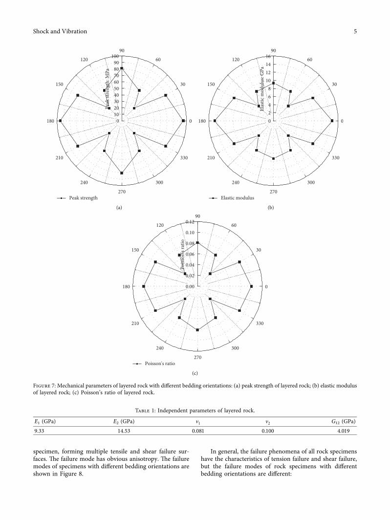
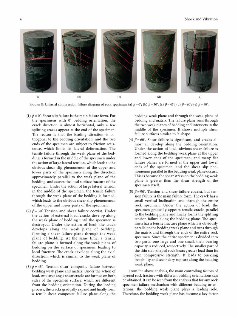