Embed Size (px)
Citation preview
1
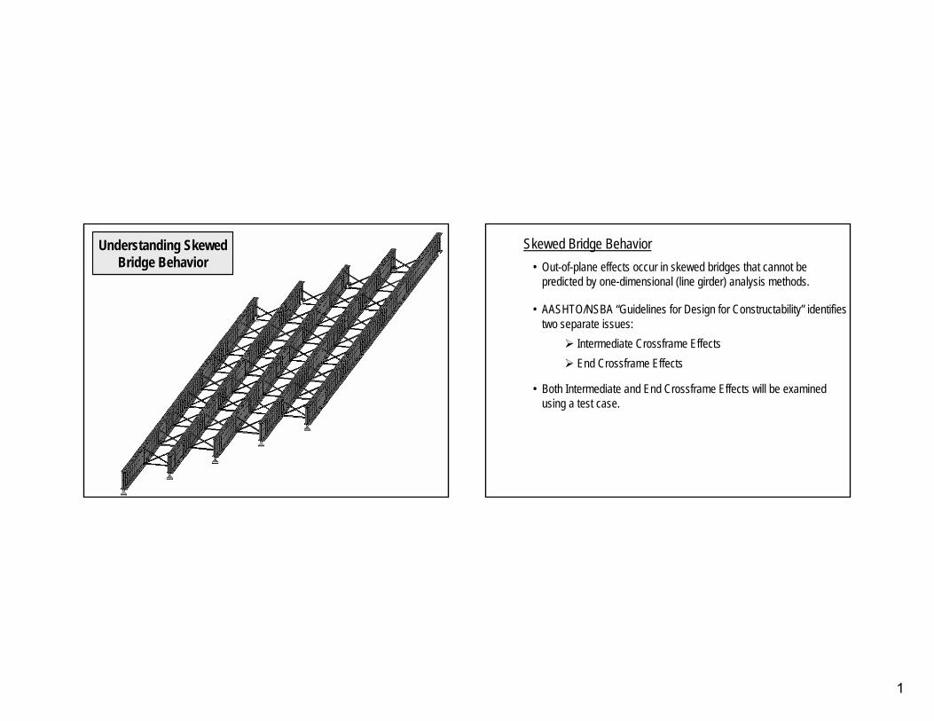
Understanding SkewedUnderstanding SkewedBridge BehaviorBridge Behavior
Skewed Bridge Behavior•• OutOut--ofof--plane effects occur in skewed bridges that cannot be plane effects occur in skewed bridges that cannot be
predicted by onepredicted by one--dimensional (line girder) analysis methods.dimensional (line girder) analysis methods.
•• AASHTO/NSBA “Guidelines for Design for Constructability” identifAASHTO/NSBA “Guidelines for Design for Constructability” identifies ies two separate issues:two separate issues:
Intermediate Crossframe EffectsIntermediate Crossframe EffectsEnd Crossframe EffectsEnd Crossframe Effects
•• Both Intermediate and End Crossframe Effects will be examined Both Intermediate and End Crossframe Effects will be examined using a test case.using a test case.
2
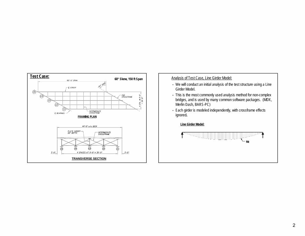
Test Case: 60° Skew, 150 ft Span
FRAMING PLAN
TRANSVERSE SECTION
Analysis of Test Case, Line Girder Model:Analysis of Test Case, Line Girder Model:• We will conduct an initial analysis of the test structure using a Line
Girder Model.• This is the most commonly used analysis method for non-complex
bridges, and is used by many common software packages. (MDX, Merlin Dash, BARS-PC)
• Each girder is modeled independently, with crossframe effects ignored.
Mz
Line Girder Model:
3
0
1
2
3
4
5
6
0 25 50 75 100 125 150
Length (ft)
Defle
ctio
n (in
)
Exterior Girders(G1, G5)
Interior Girders(G2, G3, G4)
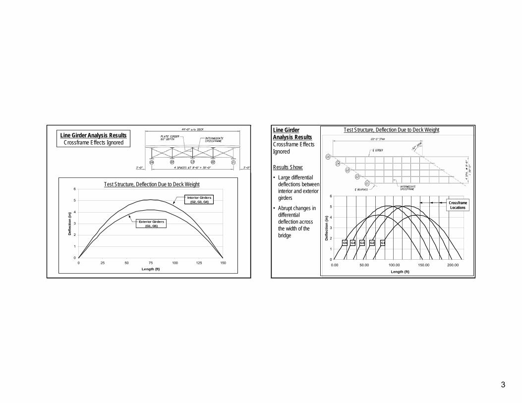
Test Structure, Deflection Due to Deck Weight
Line Girder Analysis ResultsCrossframe Effects Ignored
Line Girder Analysis ResultsCrossframe Effects Ignored
0
1
2
3
4
5
6
0.00 50.00 100.00 150.00 200.00
Length (ft)
Def
lect
ion
(in)
G2 G1G3G4G5
Crossframe Locations
Test Structure, Deflection Due to Deck Weight
Results Show:
• Large differential deflections between interior and exterior girders
• Abrupt changes in differential deflection across the width of the bridge
4
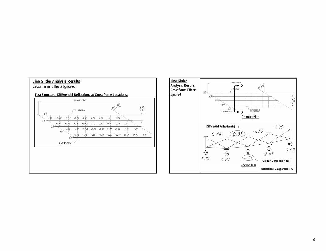
Line Girder Analysis ResultsLine Girder Analysis ResultsCrossframe Effects IgnoredCrossframe Effects Ignored
Test Structure, Differential Deflections at Crossframe Locations:
DD
DD
Section D-D
Differential Deflection (in)
Girder Deflection (in)
Deflections Exaggerated x 12Deflections Exaggerated x 12
Framing Plan
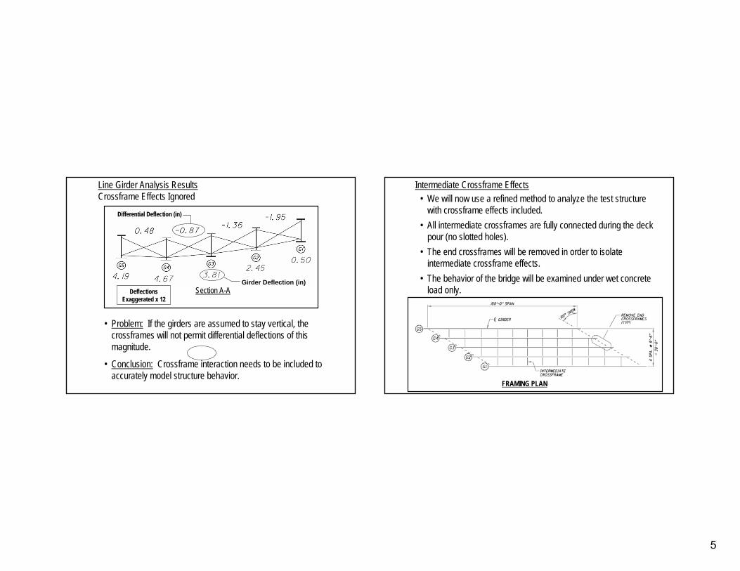
Line Girder Analysis ResultsCrossframe Effects Ignored
5
•• Problem:Problem: If the girders are assumed to stay vertical, the If the girders are assumed to stay vertical, the crossframes will not permit differential deflections of this crossframes will not permit differential deflections of this magnitude.magnitude.
•• Conclusion:Conclusion: Crossframe interaction needs to be included to Crossframe interaction needs to be included to accurately model structure behavior.accurately model structure behavior.
Line Girder Analysis ResultsLine Girder Analysis ResultsCrossframe Effects IgnoredCrossframe Effects Ignored
Section A-A
Differential Deflection (in)
Girder Deflection (in)Deflections Deflections
Exaggerated x 12Exaggerated x 12
• We will now use a refined method to analyze the test structure with crossframe effects included.
• All intermediate crossframes are fully connected during the deckpour (no slotted holes).
• The end crossframes will be removed in order to isolate intermediate crossframe effects.
• The behavior of the bridge will be examined under wet concrete load only.
FRAMING PLAN
Intermediate Crossframe Effects
6
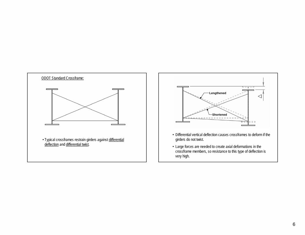
ODOT Standard Crossframe:
•• Typical crossframes restrain girders against Typical crossframes restrain girders against differential differential deflectiondeflection and and differential twistdifferential twist..
•• Differential vertical deflection causes crossframes to deform ifDifferential vertical deflection causes crossframes to deform if the the girders do not twist.girders do not twist.
•• Large forces are needed to create axial deformations in the Large forces are needed to create axial deformations in the crossframe members, so resistance to this type of deflection is crossframe members, so resistance to this type of deflection is very high.very high.
LengthenedLengthened
ShortenedShortened
7
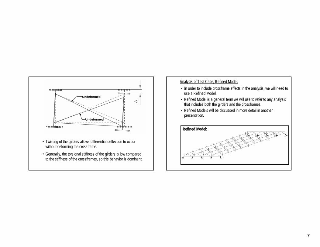
•• Twisting of the girders allows differential deflection to occur Twisting of the girders allows differential deflection to occur without deforming the crossframe.without deforming the crossframe.
•• Generally, the torsional stiffness of the girders is low compareGenerally, the torsional stiffness of the girders is low compared d to the stiffness of the crossframes, so this behavior is dominanto the stiffness of the crossframes, so this behavior is dominant.t.
UndeformedUndeformed
UndeformedUndeformed
Analysis of Test Case, Refined Model:Analysis of Test Case, Refined Model:• In order to include crossframe effects in the analysis, we will need to
use a Refined Model.• Refined Model is a general term we will use to refer to any analysis
that includes both the girders and the crossframes.• Refined Models will be discussed in more detail in another
presentation.
Refined Model:
8
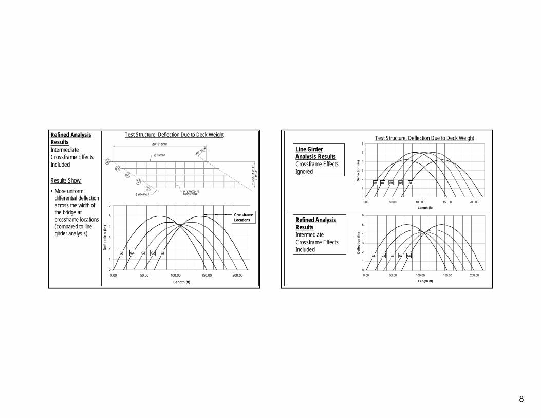
Refined Analysis ResultsIntermediate Crossframe Effects Included
Results Show:
• More uniform differential deflection across the width of the bridge at crossframe locations (compared to line girder analysis)
Test Structure, Deflection Due to Deck Weight
0
1
2
3
4
5
6
0.00 50.00 100.00 150.00 200.00
Length (ft)
Defle
ctio
n (in
)
G2 G1G3G4G5
Crossframe Locations Refined Analysis
ResultsIntermediate Crossframe Effects Included
0
1
2
3
4
5
6
0.00 50.00 100.00 150.00 200.00
Length (ft)
Def
lect
ion
(in)
G2 G1G3G4G5
0
1
2
3
4
5
6
0.00 50.00 100.00 150.00 200.00
Length (ft)
Defle
ctio
n (in
)
G2 G1G3G4G5
Test Structure, Deflection Due to Deck Weight
Line Girder Analysis ResultsCrossframe Effects Ignored
9
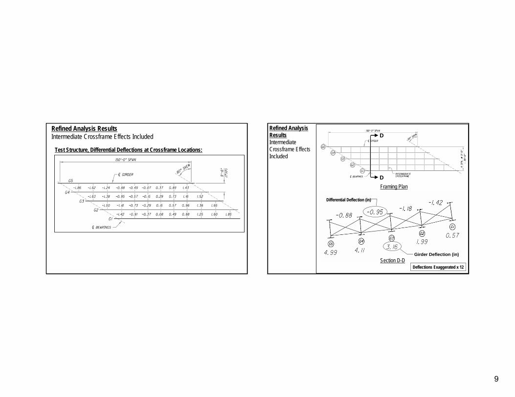
Refined Analysis ResultsRefined Analysis ResultsIntermediate Crossframe Effects IncludedIntermediate Crossframe Effects Included
Test Structure, Differential Deflections at Crossframe Locations:
DD
DD
Section D-D
Differential Deflection (in)
Girder Deflection (in)
Deflections Exaggerated x 12Deflections Exaggerated x 12
Framing Plan
Refined Analysis ResultsIntermediateCrossframe Effects Included
10
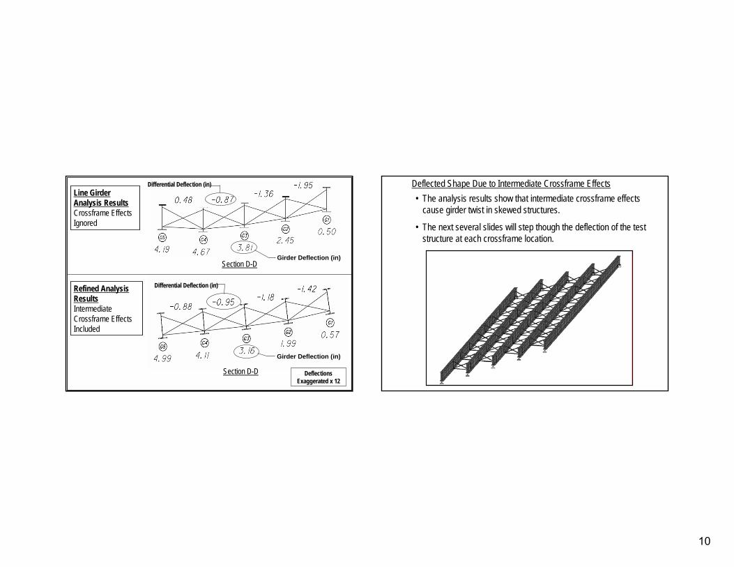
Refined Analysis ResultsIntermediate Crossframe Effects Included
Section D-D
Differential Deflection (in)
Girder Deflection (in)
Deflections Deflections Exaggerated x 12Exaggerated x 12
Section D-D
Differential Deflection (in)
Girder Deflection (in)
Line Girder Analysis ResultsCrossframe Effects Ignored
•• The analysis results show that intermediate crossframe effects The analysis results show that intermediate crossframe effects cause girder twist in skewed structures.cause girder twist in skewed structures.
•• The next several slides will step though the deflection of the tThe next several slides will step though the deflection of the test est structure at each crossframe location.structure at each crossframe location.
Deflected Shape Due to Intermediate Crossframe EffectsDeflected Shape Due to Intermediate Crossframe Effects
11
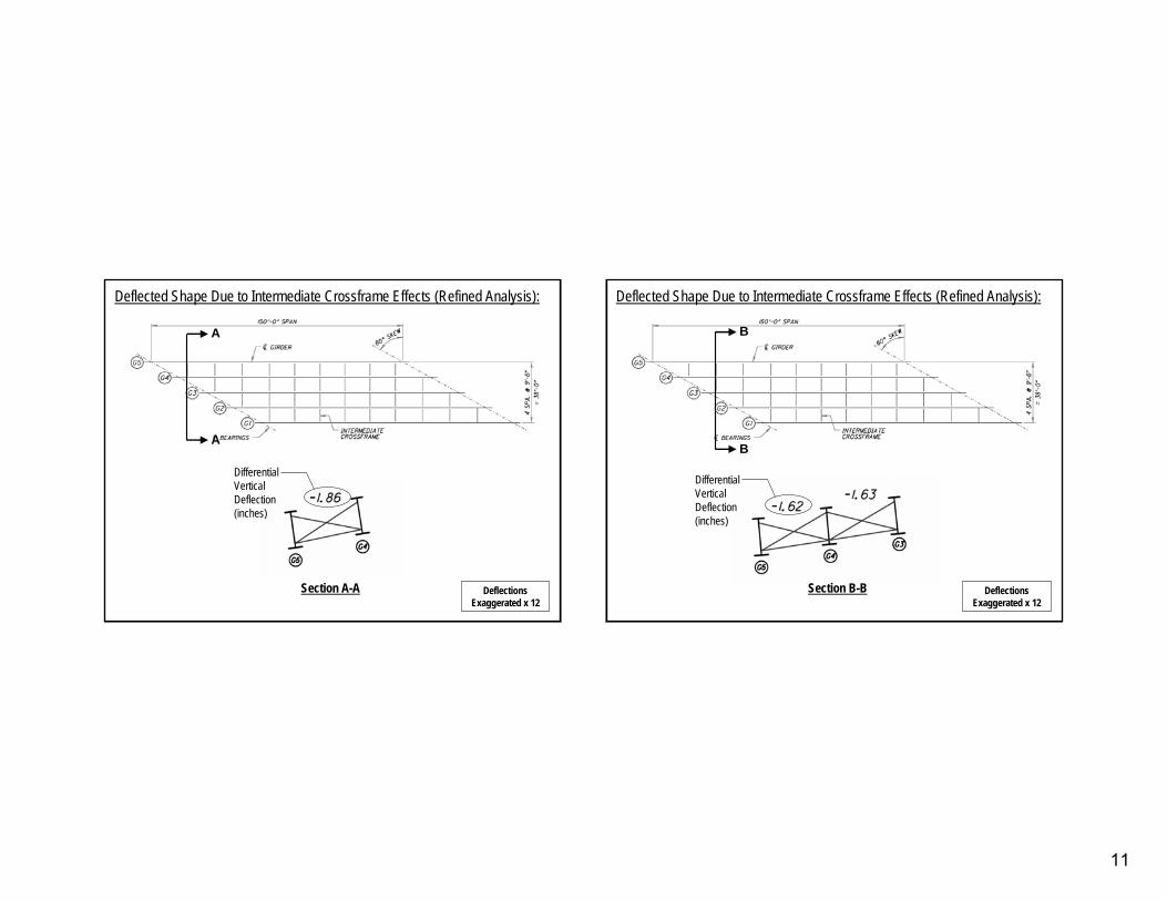
Deflected Shape Due to Intermediate Crossframe Effects (Refined Analysis):
AA
AA
Deflections Deflections Exaggerated x 12Exaggerated x 12
Section A-A
Differential Vertical Deflection (inches)
BB
BB
Deflections Deflections Exaggerated x 12Exaggerated x 12
Deflected Shape Due to Intermediate Crossframe Effects (Refined Analysis):
Section B-B
Differential Vertical Deflection (inches)
12
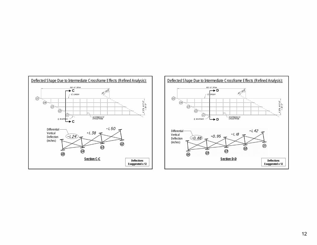
Deflections Deflections Exaggerated x 12Exaggerated x 12
Section C-C
CC
CC
Deflected Shape Due to Intermediate Crossframe Effects (Refined Analysis):
Differential Vertical Deflection (inches)
DD
DD
Deflections Deflections Exaggerated x 12Exaggerated x 12
Section D-D
Deflected Shape Due to Intermediate Crossframe Effects (Refined Analysis):
Differential Vertical Deflection (inches)
13
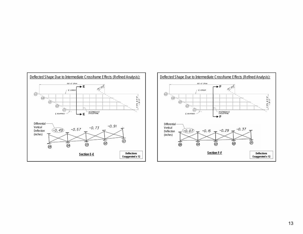
EE
EE
Deflections Deflections Exaggerated x 12Exaggerated x 12
Section E-E
Deflected Shape Due to Intermediate Crossframe Effects (Refined Analysis):
Differential Vertical Deflection (inches)
FF
FF
Deflections Deflections Exaggerated x 12Exaggerated x 12
Section F-F
Deflected Shape Due to Intermediate Crossframe Effects (Refined Analysis):
Differential Vertical Deflection (inches)
14
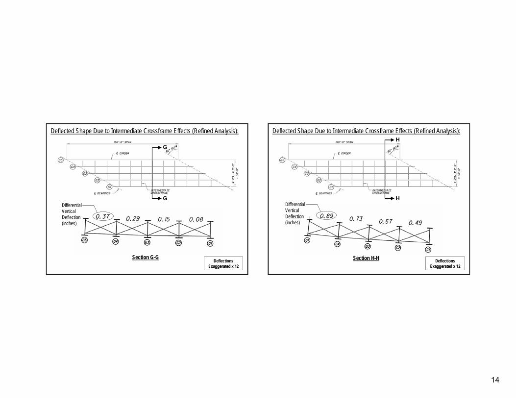
Deflections Deflections Exaggerated x 12Exaggerated x 12
Section G-G
GG
GG
Deflected Shape Due to Intermediate Crossframe Effects (Refined Analysis):
Differential Vertical Deflection (inches)
HH
HH
Deflections Deflections Exaggerated x 12Exaggerated x 12
Section H-H
Deflected Shape Due to Intermediate Crossframe Effects (Refined Analysis):
Differential Vertical Deflection (inches)
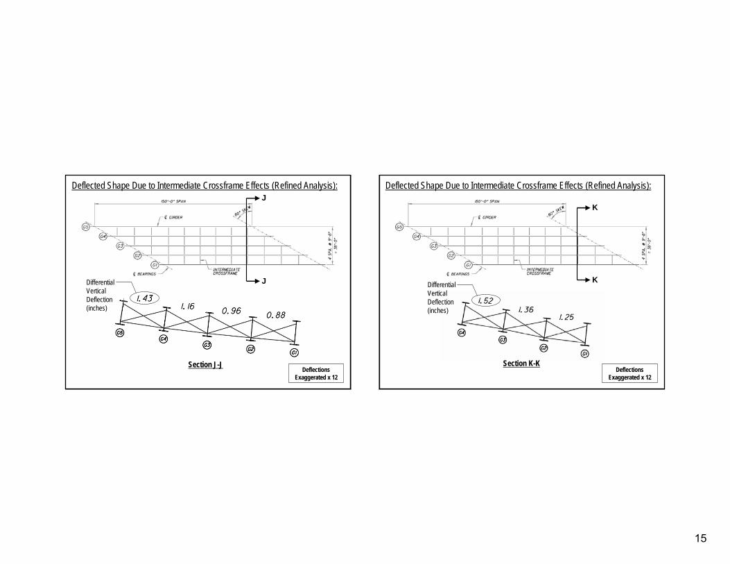
15
JJ
JJ
Deflections Deflections Exaggerated x 12Exaggerated x 12
Deflected Shape Due to Intermediate Crossframe Effects (Refined Analysis):
Section J-J
Differential Vertical Deflection (inches)
KK
KK
Deflections Deflections Exaggerated x 12Exaggerated x 12
Deflected Shape Due to Intermediate Crossframe Effects (Refined Analysis):
Section K-K
Differential Vertical Deflection (inches)
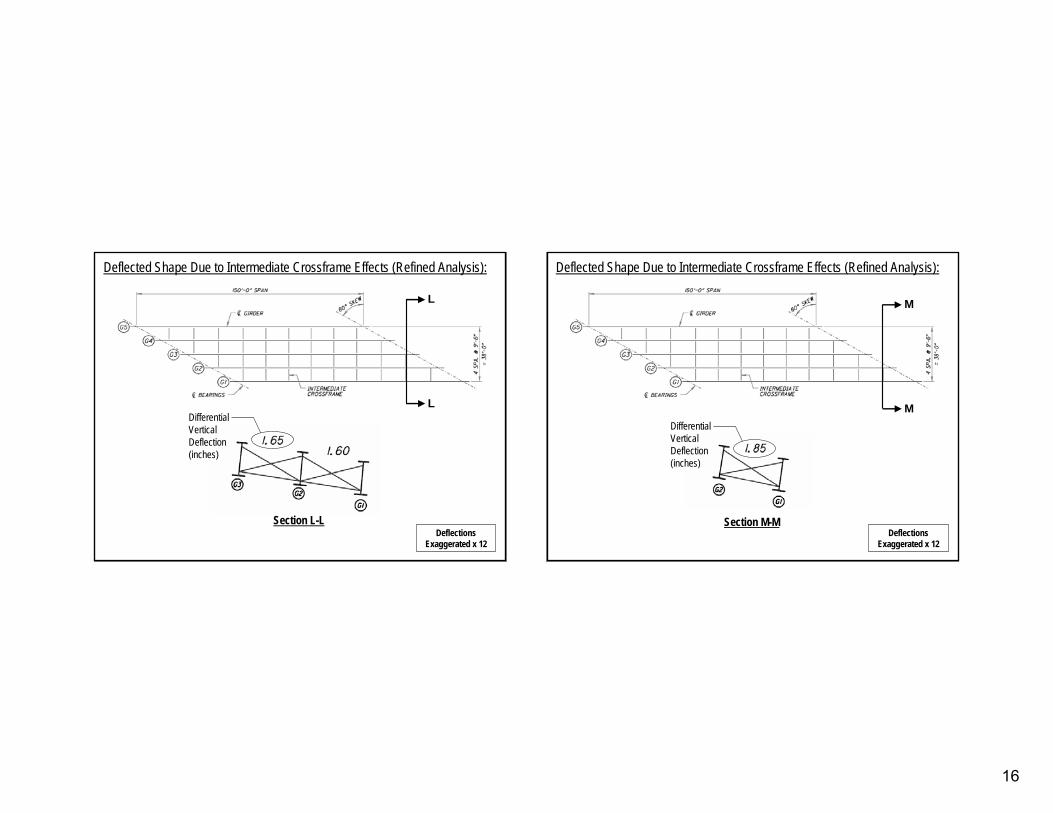
16
LL
LL
Deflections Deflections Exaggerated x 12Exaggerated x 12
Section L-L
Deflected Shape Due to Intermediate Crossframe Effects (Refined Analysis):
Differential Vertical Deflection (inches)
MM
MM
Deflections Deflections Exaggerated x 12Exaggerated x 12
Section M-M
Deflected Shape Due to Intermediate Crossframe Effects (Refined Analysis):
Differential Vertical Deflection (inches)
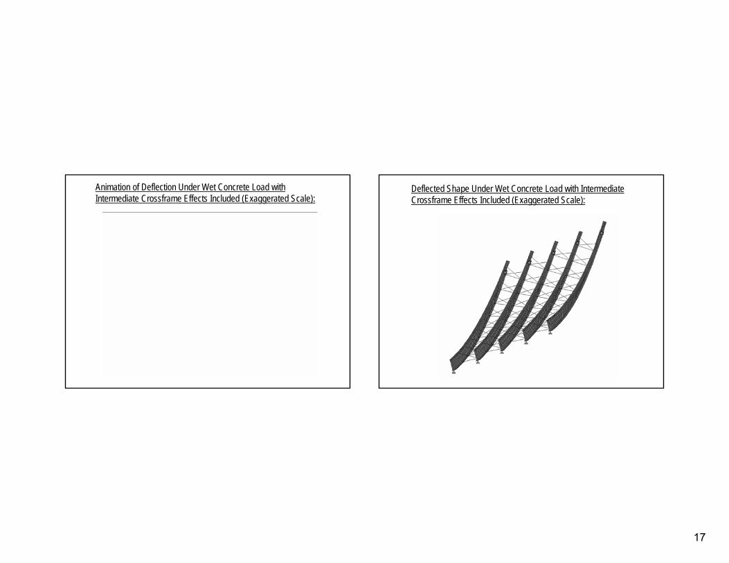
17
Animation of Deflection Under Wet Concrete Load with Animation of Deflection Under Wet Concrete Load with Intermediate Crossframe Effects Included (Exaggerated Scale):Intermediate Crossframe Effects Included (Exaggerated Scale):
Deflected Shape Under Wet Concrete Load with Intermediate Deflected Shape Under Wet Concrete Load with Intermediate Crossframe Effects Included (Exaggerated Scale):Crossframe Effects Included (Exaggerated Scale):
18
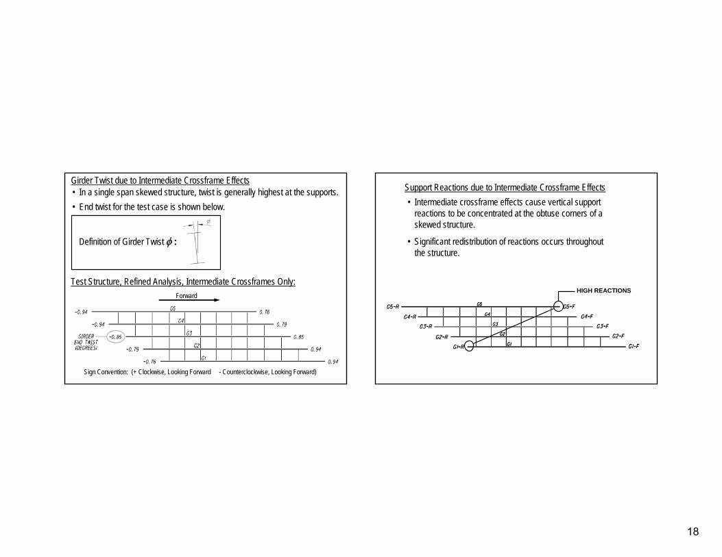
Test Structure, Refined Analysis, Intermediate Crossframes Only:Test Structure, Refined Analysis, Intermediate Crossframes Only:
•• In a single span skewed structure, twist is generally highest atIn a single span skewed structure, twist is generally highest at the supports.the supports.•• End twist for the test case is shown below.End twist for the test case is shown below.
Definition of Girder Twist Definition of Girder Twist φφ ::
Girder Twist due to Intermediate Crossframe EffectsGirder Twist due to Intermediate Crossframe Effects
Sign Convention: (+ Clockwise, Looking Forward Sign Convention: (+ Clockwise, Looking Forward -- Counterclockwise, Looking Forward)Counterclockwise, Looking Forward)
ForwardForward
Support Reactions due to Intermediate Crossframe EffectsSupport Reactions due to Intermediate Crossframe Effects
HIGH REACTIONS
•• Intermediate crossframe effects cause vertical support Intermediate crossframe effects cause vertical support reactions to be concentrated at the obtuse corners of a reactions to be concentrated at the obtuse corners of a skewed structure.skewed structure.
•• Significant redistribution of reactions occurs throughout Significant redistribution of reactions occurs throughout the structure.the structure.
19
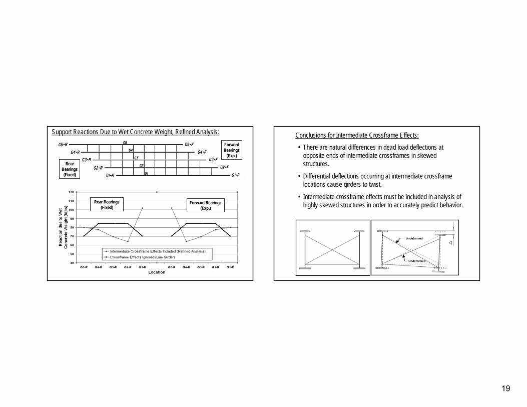
Support Reactions Due to Wet Concrete Weight, Refined Analysis:
Rear Bearings (Fixed)
Forward Bearings (Exp.)
Rear Bearings (Fixed)
Forward Bearings
(Exp.)•• There are natural differences in dead load deflections at There are natural differences in dead load deflections at
opposite ends of intermediate crossframes in skewed opposite ends of intermediate crossframes in skewed structures.structures.
•• Differential deflections occurring at intermediate crossframe Differential deflections occurring at intermediate crossframe locations cause girders to twist.locations cause girders to twist.
•• Intermediate crossframe effects must be included in analysis of Intermediate crossframe effects must be included in analysis of highly skewed structures in order to accurately predict behaviorhighly skewed structures in order to accurately predict behavior..
Conclusions for Intermediate Crossframe Effects:Conclusions for Intermediate Crossframe Effects:
UndeformedUndeformed
UndeformedUndeformed
20
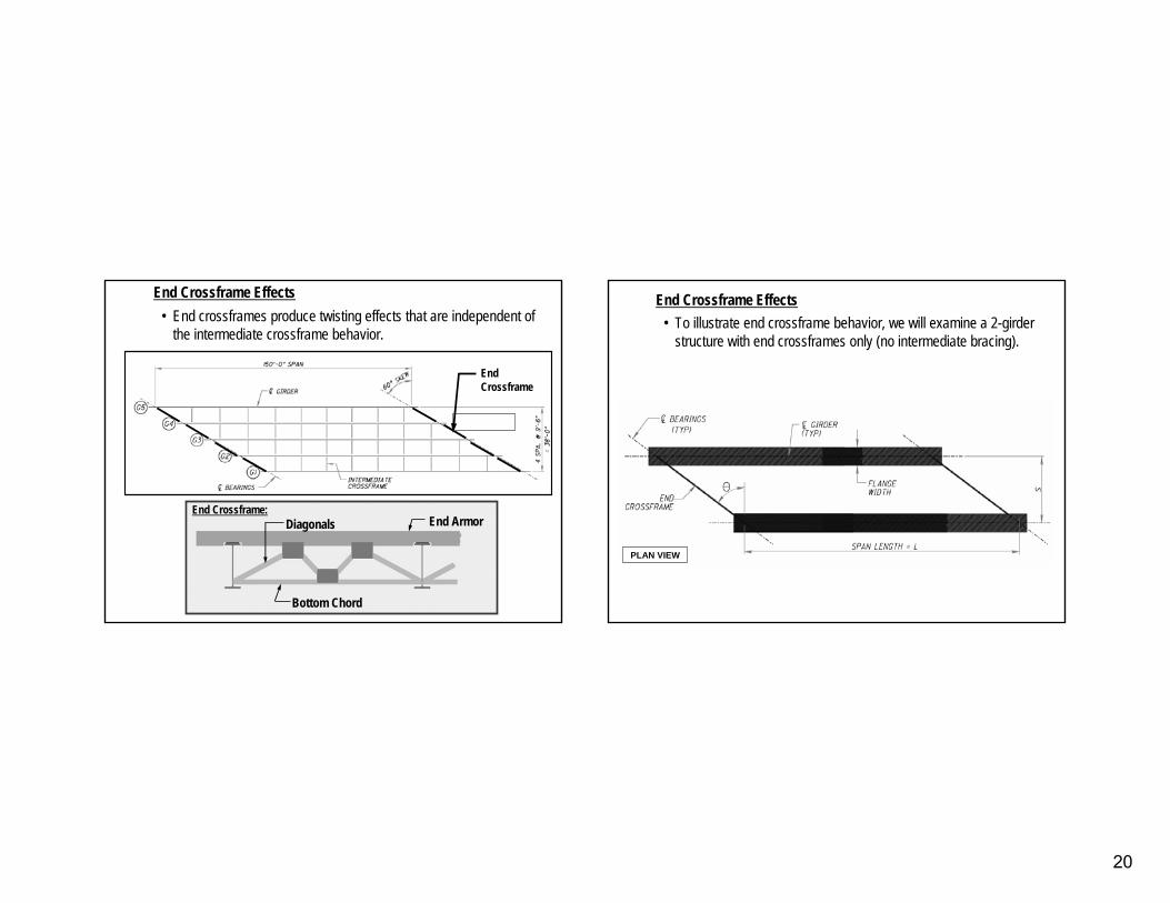
End Crossframe EffectsEnd Crossframe Effects•• End crossframes produce twisting effects that are independent ofEnd crossframes produce twisting effects that are independent of
the intermediate crossframe behavior.the intermediate crossframe behavior.
End Armor
Bottom Chord
Diagonals
End Crossframe
End Crossframe:
End Crossframe EffectsEnd Crossframe Effects• To illustrate end crossframe behavior, we will examine a 2-girder
structure with end crossframes only (no intermediate bracing).
PLAN VIEWPLAN VIEW
21
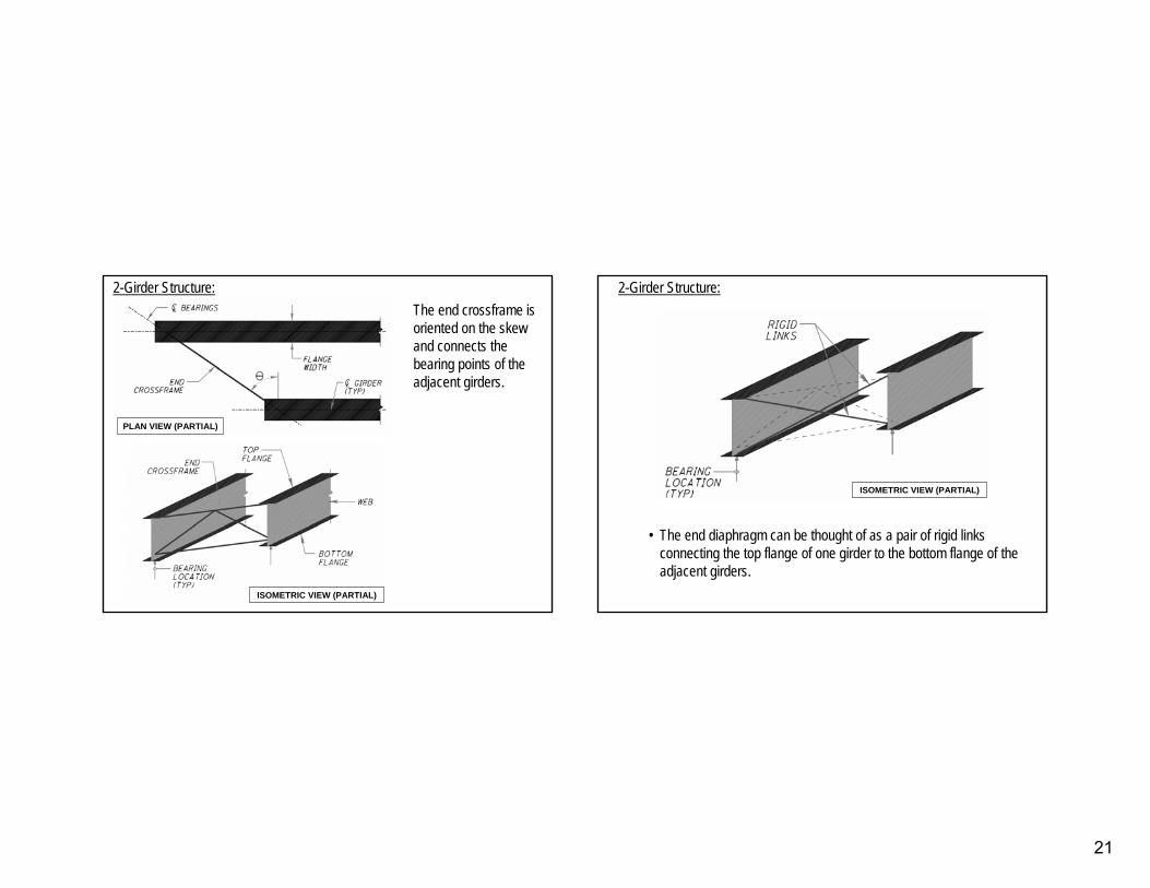
PLAN VIEW (PARTIAL)PLAN VIEW (PARTIAL)
ISOMETRIC VIEW (PARTIAL)ISOMETRIC VIEW (PARTIAL)
2-Girder Structure:The end crossframe is oriented on the skew and connects the bearing points of the adjacent girders.
•• The end diaphragm can be thought of as a pair of rigid links The end diaphragm can be thought of as a pair of rigid links connecting the top flange of one girder to the bottom flange of connecting the top flange of one girder to the bottom flange of the the adjacent girders.adjacent girders.
2-Girder Structure:
ISOMETRIC VIEW (PARTIAL)ISOMETRIC VIEW (PARTIAL)
22
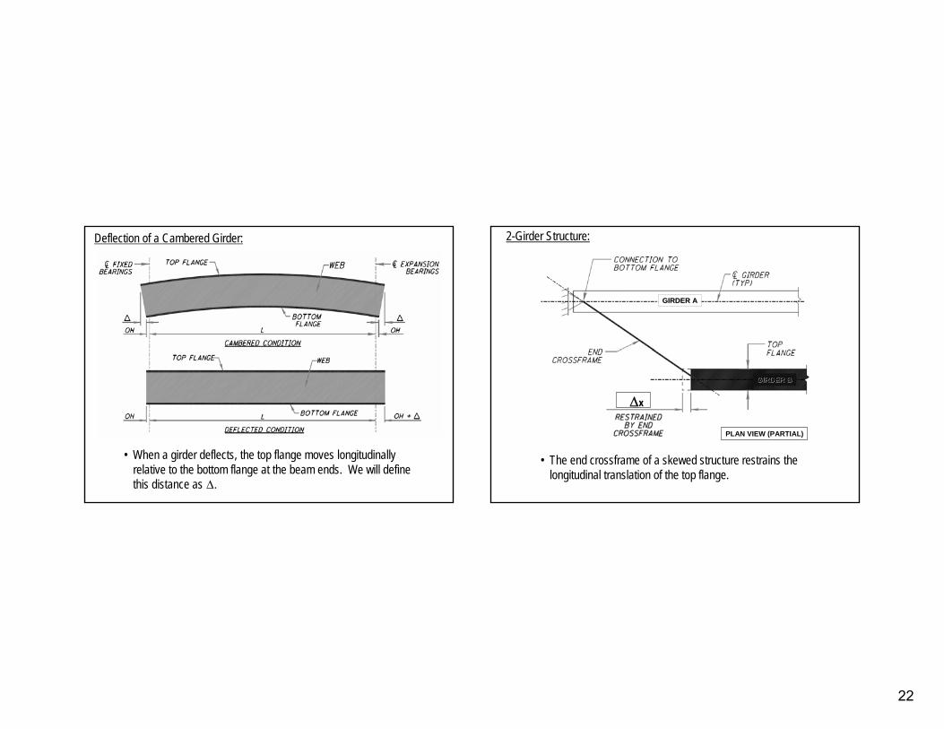
Deflection of a Cambered Girder:Deflection of a Cambered Girder:
•• When a girder deflects, the top flange moves longitudinally When a girder deflects, the top flange moves longitudinally relative to the bottom flange at the beam ends. We will define relative to the bottom flange at the beam ends. We will define this distance asthis distance as ∆∆..
•• The end crossframe of a skewed structure restrains the The end crossframe of a skewed structure restrains the longitudinal translation of the top flange. longitudinal translation of the top flange.
2-Girder Structure:
PLAN VIEW (PARTIAL)PLAN VIEW (PARTIAL)
∆x
GIRDER AGIRDER A
GIRDER BGIRDER B
23
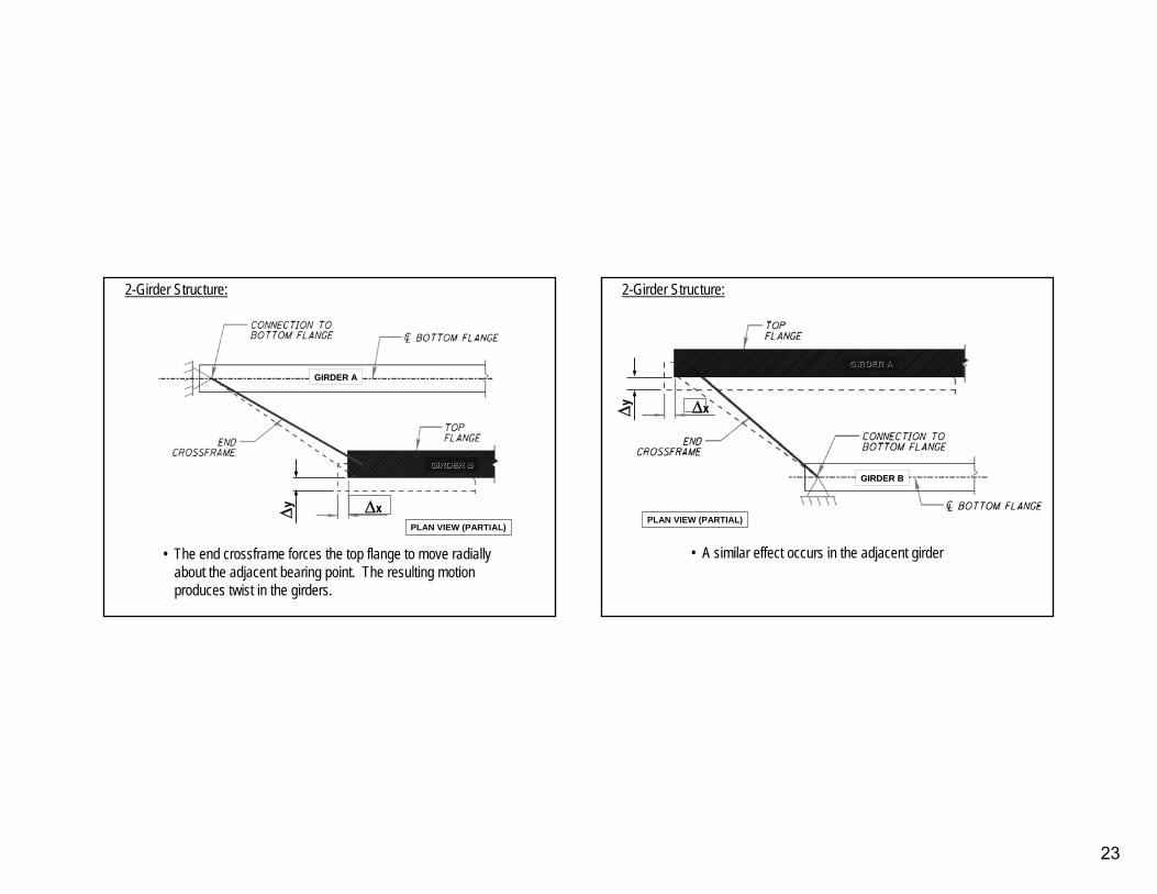
•• The end crossframe forces the top flange to move radially The end crossframe forces the top flange to move radially about the adjacent bearing point. The resulting motion about the adjacent bearing point. The resulting motion produces twist in the girders.produces twist in the girders.
2-Girder Structure:
PLAN VIEW (PARTIAL)PLAN VIEW (PARTIAL)
∆x∆y
GIRDER AGIRDER A
GIRDER BGIRDER B
•• A similar effect occurs in the adjacent girderA similar effect occurs in the adjacent girder
2-Girder Structure:
PLAN VIEW (PARTIAL)PLAN VIEW (PARTIAL)
∆∆xx∆∆yy
GIRDER BGIRDER B
GIRDER AGIRDER A
24
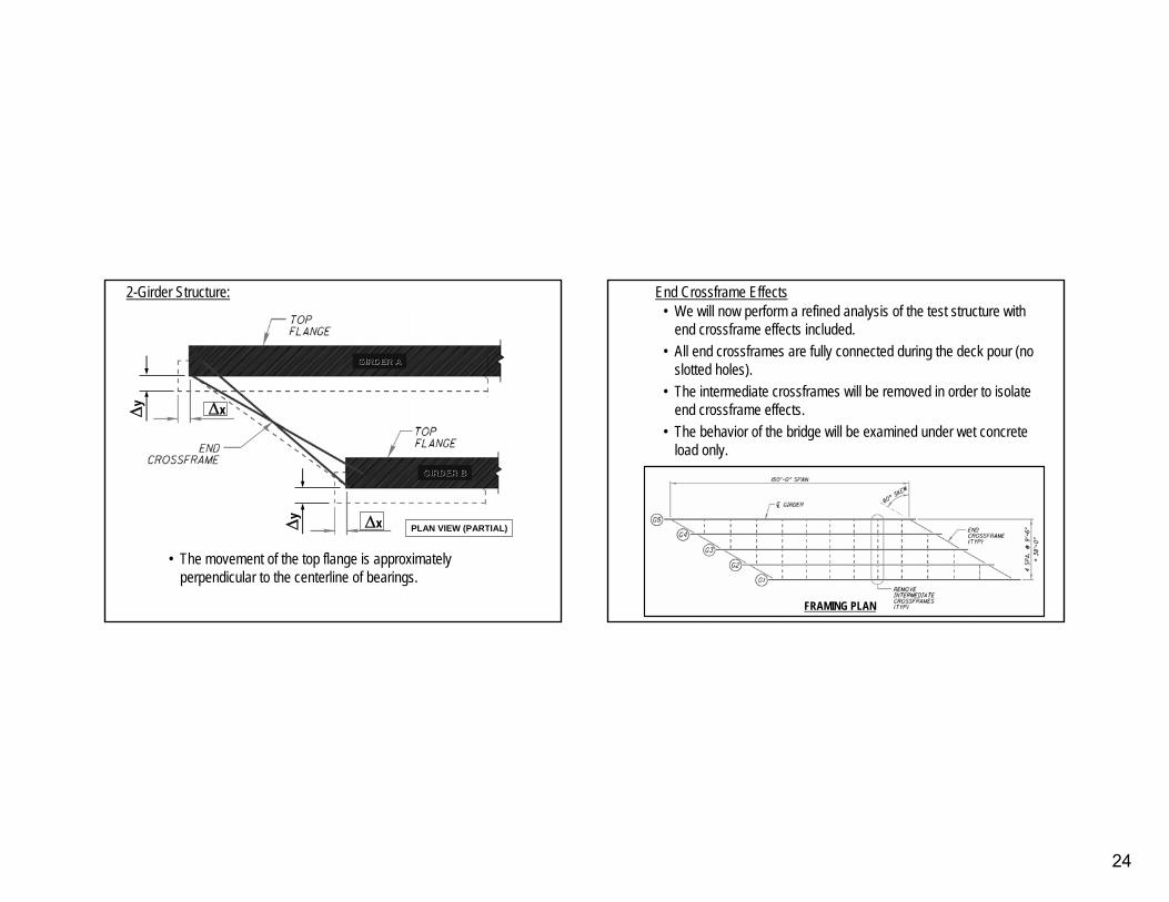
•• The movement of the top flange is approximately The movement of the top flange is approximately perpendicular to the centerline of bearings.perpendicular to the centerline of bearings.
2-Girder Structure:
PLAN VIEW (PARTIAL)PLAN VIEW (PARTIAL)
∆∆xx∆∆yy
∆∆xx∆∆yy
GIRDER BGIRDER B
GIRDER AGIRDER A
• We will now perform a refined analysis of the test structure with end crossframe effects included.
• All end crossframes are fully connected during the deck pour (noslotted holes).
• The intermediate crossframes will be removed in order to isolateend crossframe effects.
• The behavior of the bridge will be examined under wet concrete load only.
FRAMING PLAN
End Crossframe Effects
25
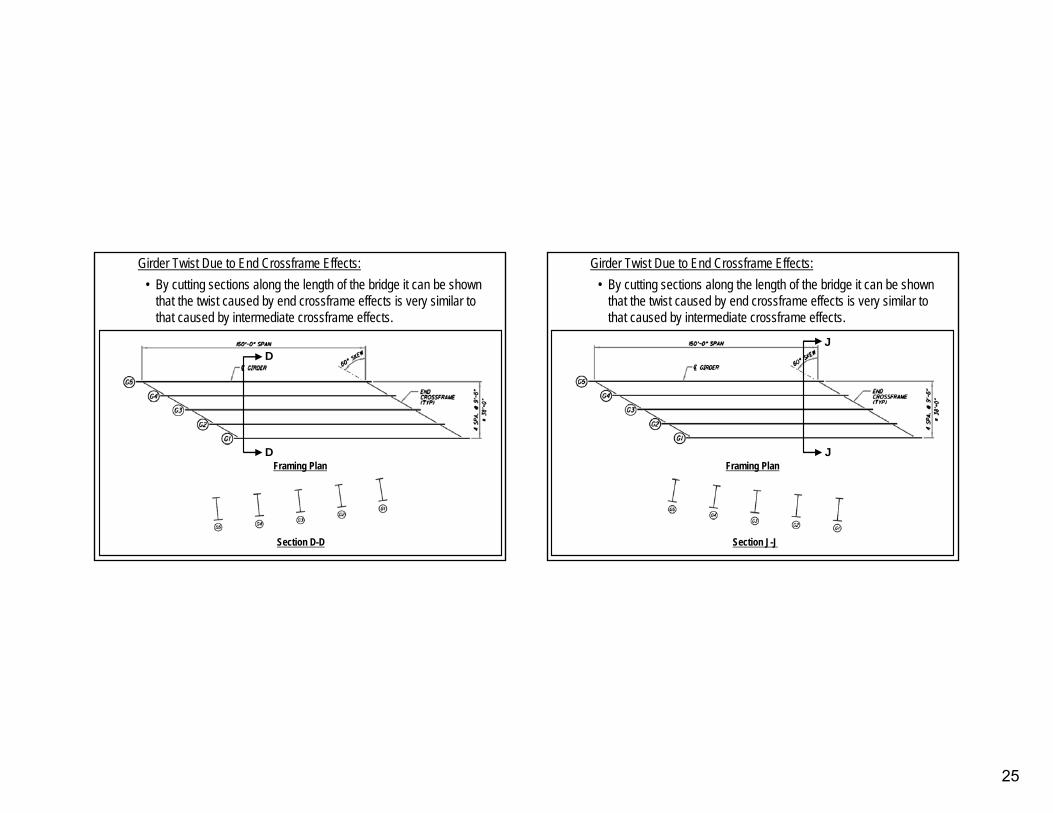
• By cutting sections along the length of the bridge it can be shown that the twist caused by end crossframe effects is very similar to that caused by intermediate crossframe effects.
Girder Twist Due to End Crossframe Effects:
DD
DDFraming Plan
Section D-D
• By cutting sections along the length of the bridge it can be shown that the twist caused by end crossframe effects is very similar to that caused by intermediate crossframe effects.
Girder Twist Due to End Crossframe Effects:
JJ
JJFraming Plan
Section J-J
26
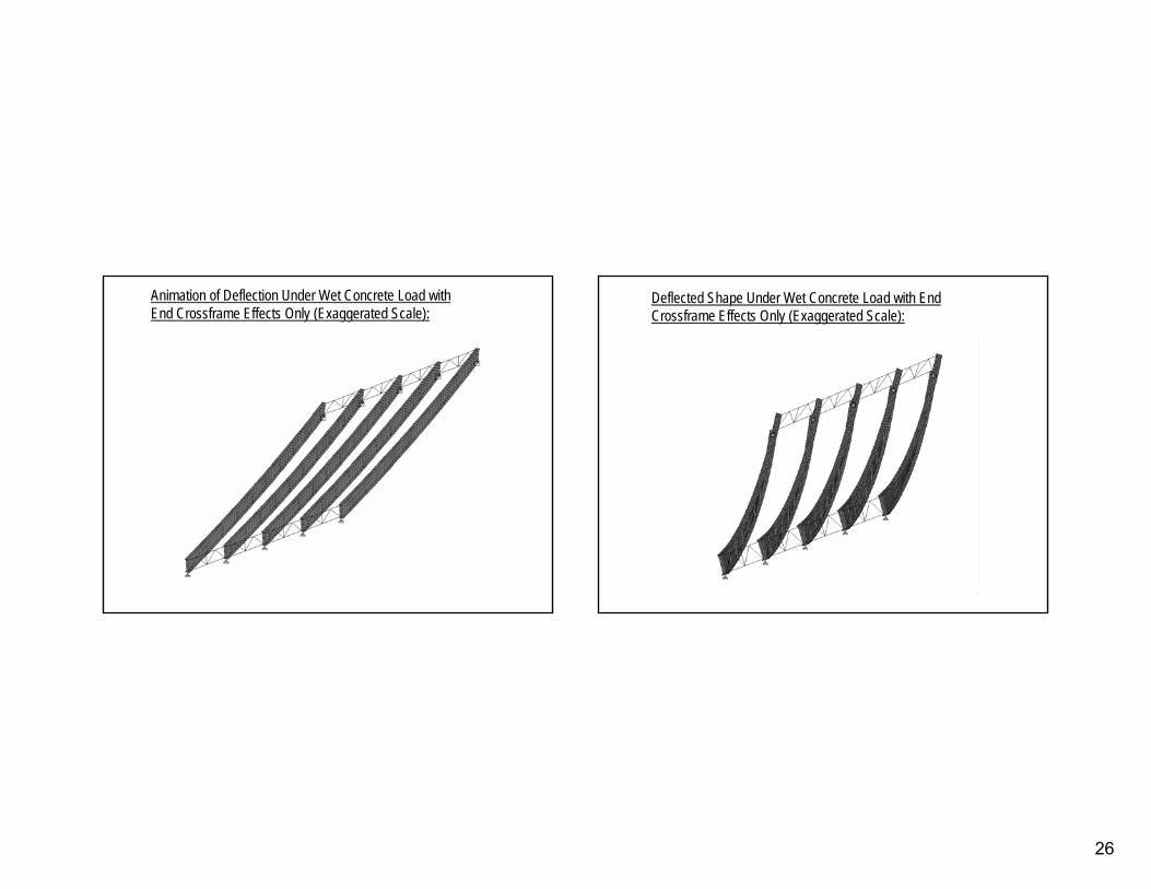
Animation of Deflection Under Wet Concrete Load with Animation of Deflection Under Wet Concrete Load with End Crossframe Effects Only (Exaggerated Scale):End Crossframe Effects Only (Exaggerated Scale):
Deflected Shape Under Wet Concrete Load with End Deflected Shape Under Wet Concrete Load with End Crossframe Effects Only (Exaggerated Scale):Crossframe Effects Only (Exaggerated Scale):
27
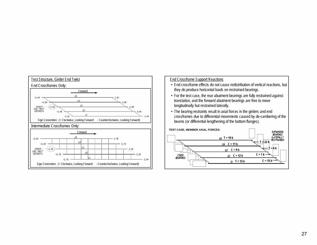
Test Structure, Girder End TwistTest Structure, Girder End TwistEnd Crossframes Only:End Crossframes Only:
Intermediate Crossframes Only:Intermediate Crossframes Only:
Sign Convention: (+ Clockwise, Looking Forward Sign Convention: (+ Clockwise, Looking Forward -- Counterclockwise, Looking Forward)Counterclockwise, Looking Forward)
ForwardForward
Sign Convention: (+ Clockwise, Looking Forward Sign Convention: (+ Clockwise, Looking Forward -- Counterclockwise, Looking Forward)Counterclockwise, Looking Forward)
ForwardForward
•• End crossframe effects do not cause redistribution of vertical rEnd crossframe effects do not cause redistribution of vertical reactions, but eactions, but they do produce horizontal loads on restrained bearings.they do produce horizontal loads on restrained bearings.
•• For the test case, the rear abutment bearings are fully restrainFor the test case, the rear abutment bearings are fully restrained against ed against translation, and the forward abutment bearings are free to move translation, and the forward abutment bearings are free to move longitudinally but restrained laterally.longitudinally but restrained laterally.
•• The bearing restraints result in axial forces in the girders andThe bearing restraints result in axial forces in the girders and end end crossframes due to differential movements caused by decrossframes due to differential movements caused by de--cambering of the cambering of the beams (or differential lengthening of the bottom flanges).beams (or differential lengthening of the bottom flanges).
End Crossframe Support ReactionsEnd Crossframe Support Reactions
TEST CASE, MEMBER AXIAL FORCES:TEST CASE, MEMBER AXIAL FORCES:
6
T = 19 k
C = 11 k
T = 13 k
C = 9 k
C = 12 k
T = 22 k
T = 6 k
C = 1 k
C = 15 k
28
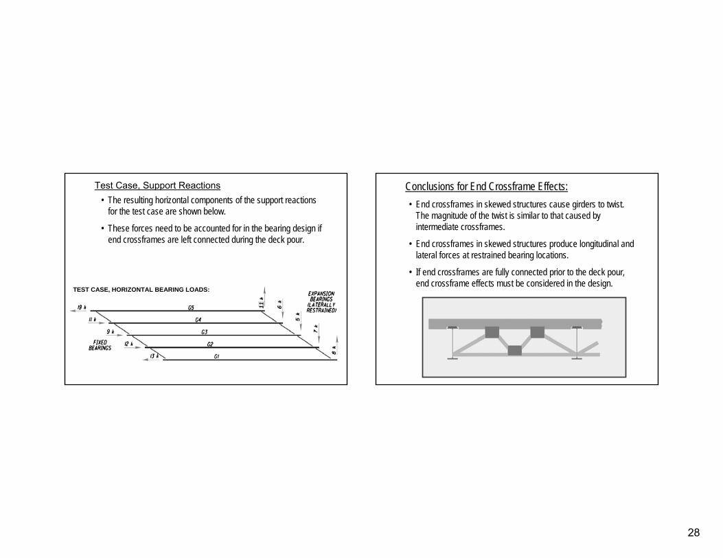
Test Case, Support ReactionsTest Case, Support Reactions•• The resulting horizontal components of the support reactions The resulting horizontal components of the support reactions
for the test case are shown below.for the test case are shown below.
•• These forces need to be accounted for in the bearing design if These forces need to be accounted for in the bearing design if end crossframes are left connected during the deck pour.end crossframes are left connected during the deck pour.
TEST CASE, HORIZONTAL BEARING LOADS:TEST CASE, HORIZONTAL BEARING LOADS:
11
•• End crossframes in skewed structures cause girders to twist. End crossframes in skewed structures cause girders to twist. The magnitude of the twist is similar to that caused by The magnitude of the twist is similar to that caused by intermediate crossframes.intermediate crossframes.
•• End crossframes in skewed structures produce longitudinal and End crossframes in skewed structures produce longitudinal and lateral forces at restrained bearing locations.lateral forces at restrained bearing locations.
•• If end crossframes are fully connected prior to the deck pour, If end crossframes are fully connected prior to the deck pour, end crossframe effects must be considered in the design.end crossframe effects must be considered in the design.
Conclusions for End Crossframe Effects:Conclusions for End Crossframe Effects:
29
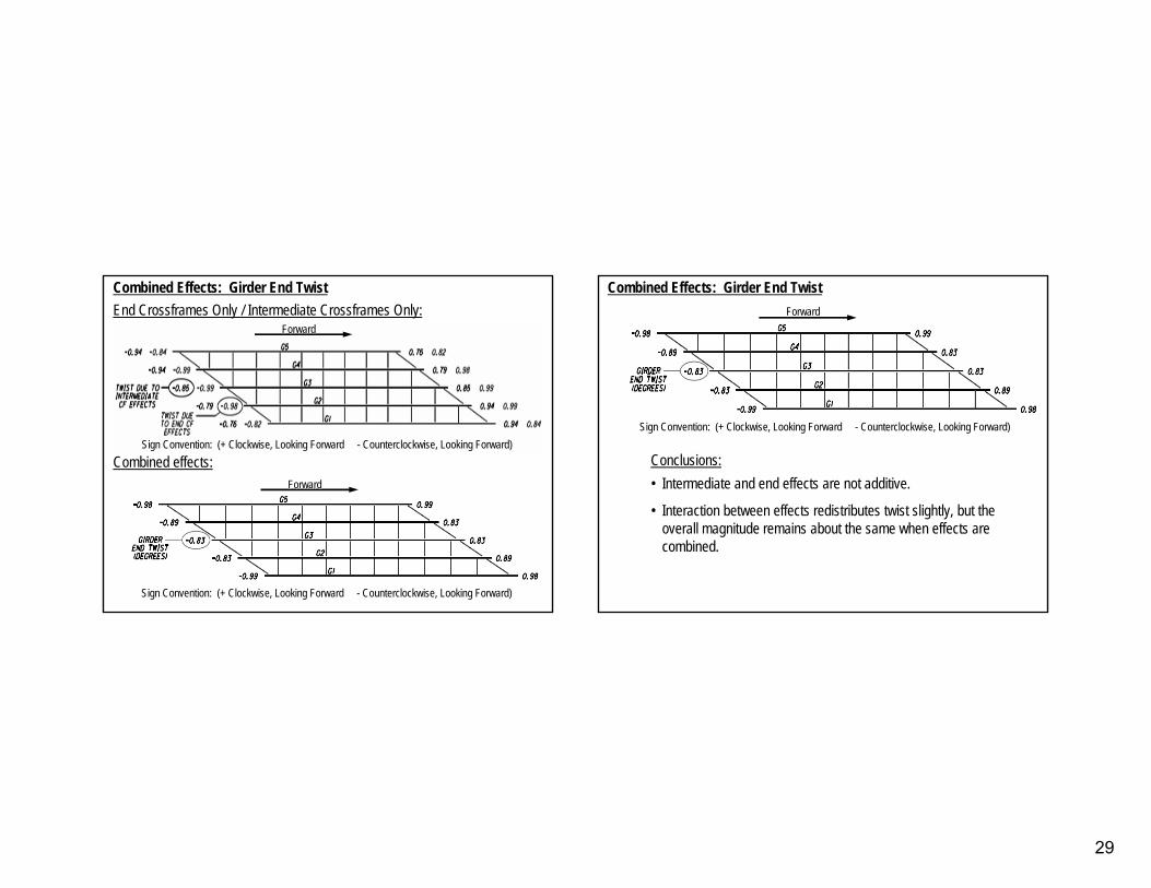
Combined Effects: Girder End TwistCombined Effects: Girder End TwistEnd Crossframes Only / Intermediate Crossframes Only:End Crossframes Only / Intermediate Crossframes Only:
Combined effects:Combined effects:
Sign Convention: (+ Clockwise, Looking Forward Sign Convention: (+ Clockwise, Looking Forward -- Counterclockwise, Looking Forward)Counterclockwise, Looking Forward)
ForwardForward
Sign Convention: (+ Clockwise, Looking Forward Sign Convention: (+ Clockwise, Looking Forward -- Counterclockwise, Looking Forward)Counterclockwise, Looking Forward)
ForwardForward
Combined Effects: Girder End TwistCombined Effects: Girder End Twist
Conclusions:Conclusions:•• Intermediate and end effects are not additive.Intermediate and end effects are not additive.
•• Interaction between effects redistributes twist slightly, but thInteraction between effects redistributes twist slightly, but the e overall magnitude remains about the same when effects are overall magnitude remains about the same when effects are combined.combined.
Sign Convention: (+ Clockwise, Looking Forward Sign Convention: (+ Clockwise, Looking Forward -- Counterclockwise, Looking Forward)Counterclockwise, Looking Forward)
ForwardForward
30
Q: Will using skewed intermediate crossframes prevent girder Q: Will using skewed intermediate crossframes prevent girder twisting?twisting?
Common Questions:Common Questions:
A: No. Skewed intermediate crossframes behave like end A: No. Skewed intermediate crossframes behave like end crossframes. They will produce twist due to differential crossframes. They will produce twist due to differential movements between the bottom and top flanges of adjacent movements between the bottom and top flanges of adjacent girders.girders.
A: No. Tighter crossframe spacing does not address the basic problem, which is differential movement between adjacent girders. Adding crossframes may reduce crossframe member forces and increase girder stability, but twisting will still occur.
Q: Will reducing crossframe spacing keep girders from twisting?Q: Will reducing crossframe spacing keep girders from twisting?
Common Questions:Common Questions:
31
•• Both intermediate and end crossframes produce twist in skewed Both intermediate and end crossframes produce twist in skewed bridges.bridges.
•• Intermediate crossframes cause significant redistribution of Intermediate crossframes cause significant redistribution of support reactions and girder forces (shear and moment) in support reactions and girder forces (shear and moment) in heavily skewed structures.heavily skewed structures.
•• End crossframes may cause significant lateral and longitudinal End crossframes may cause significant lateral and longitudinal reactions to occur at restrained bearingsreactions to occur at restrained bearings
•• Both intermediate and end crossframe effects need to be Both intermediate and end crossframe effects need to be accounted for in design of highly skewed bridges.accounted for in design of highly skewed bridges.
Summary:Summary:
QUESTIONS ?QUESTIONS ?
EE--mail questions to:mail questions to:[email protected]@dot.state.oh.us