Embed Size (px)
Citation preview

BCS-041
Fundamental
of Computer Networks
Block
2 NETWORKS AND DEVICES
UNIT 1
Network Classifications and Topologies 5
UNIT 2
OSI and TCP/IP Models 22
UNIT 3
Physical and Data Link Layer 42
UNIT 4
Internet Working Devices 58
Indira Gandhi National Open University
School of Computer and
Information Sciences
PROGRAMME DESIGN COMMITTEE
Prof. Manohar Lal,
SOCIS, IGNOU, New Delhi
Prof. H.M Gupta
Dept. of Elect. Engg., IIT, Delhi
Prof. M.N Doja, Dept. of CE
Jamia Millia, New Delhi
Prof. C. Pandurangan
Dept. of CSE, IIT, Chennai
Prof. I. Ramesh Babu
Dept. of CSE
Acharya Nagarjuna University,
Nagarjuna Nagar (AP)
Prof. N.S. Gill
Dept. of CS, MDU, Rohtak
Prof. Arvind Kalia, Dept. of CS
HP University, Shimla
Prof. Anju Sehgal Gupta
SOCIS, IGNOU, New Delhi
Prof. Sujatha Verma
SOS, IGNOU, New Delhi
Prof. V. Sundarapandian
IITMK, Trivendrum
Prof. Dharamendra Kumar
Dept. of CS, GJU, Hissar
Prof. Vikram Singh
Dept. of CS, CDLU, Sirsa
Sh. Shashi Bhushan, Associate. Prof.
SOCIS, IGNOU, New Delhi
Sh. Akshay Kumar, Associate Prof.
SOCIS, IGNOU, New Delhi
Dr. P.K. Mishra, Associate Prof.
Dept. of CS, BHU, Varanasi
Sh. P.V. Suresh, Asst. Prof.
SOCIS, IGNOU, New Delhi
Sh. V.V. Subrahmanyam, Asst. Prof.
SOCIS, IGNOU, New Delhi
Sh. M.P. Mishra, Asst. Prof.
SOCIS, IGNOU, New Delhi
Dr. Naveen Kumar, Asst. Prof.
SOCIS, IGNOU, New Delhi
Dr. Subodh Kesharwani, Asst. Prof.
SOMS, IGNOU, New Delhi
COURSE CURRICULUM DESIGN COMMITTEE
Prof. R. S.Gupta, Professor (Retd.),
University of Roorkee, Roorkee,
Prof. Sujatha Varma, Profesor,
SOS, IGNOU, New Delhi
Sh. Milind Mahajani
Sr. IT Consultant, New Delhi
Dr. D.K.Lobiyal, Associate Prof.,
SC&SS, JNU, New Delhi
Sh. Akshay Kumar, Associate Prof.
SOCIS, IGNOU, New Delhi
Dr. Parvin Chandra, Associate Prof.,
IIC, Delhi University, New Delhi
Sh. P. V. Suresh, Asst. Prof.
SOCIS, IGNOU, New Delhi
Sh. M.P. Mishra, Asst. Prof.
SOCIS, IGNOU, New Delhi
Dr. Naveen kumar, Asst. Prof.
SOCIS, IGNOU, New Delhi
COURSE SOCIS FACULTY
Sh. Shashi Bhushan, Director Sh. Akshay Kumar, Associate Prof. Dr. P.V. Suresh, Associate Prof.
Sh. V.V. Subrahmanyam, Associate Prof. Dr. Naveen Kumar, Reader Sh. M.P. Mishra, Asst. Prof.
COURSE BLOCK PREPARATION TEAM
Dr. Naveen Kumar, Reader
(Unit-3 Writer),
SOCIS, IGNOU, New Delhi
Dr. Anil Ahlawat, Assoc. Prof.
(Unit-1 Writer),
Dept. of Computer Eng.
KIET, Ghaziabd,UP
Dr. M. A. Murli Rao, Joint Director,
Computer Division,
(Unit-2 and 4 Writer),
IGNOU, New Delhi
Dr. Naveen Kumar, Reader
(Unit-1,2,4 Transformation),
SOCIS, IGNOU, New Delhi
Dr. D.K.Lobiyal (Language Editor)
Assoc. Prof., SC&SS, JNU, New
Delhi
Dr. Parmod Kumar, Asst. Prof.,
(Language Editor),
SOH, IGNOU, New Delhi
Course Coordinator : Dr. Naveen Kumar, Reader, SOCIS, IGNOU, New Delhi
PRINT PRODUCTION: Sh. Tilak Raj, S.O.(P), CRC Prepared by Smt. Dolly Singh
ISBN: © Indira Gandhi National Open University, 2013
All rights reserved. No part of this work may be reproduced in any form, by mimeograph or any form, by
mimeograph or any other means, without permission in writing form the Indira Gandhi National Open
University.
Further information on the Indira Gandhi National Open University courses may be obtained from the
University’s office at Maidan Garhi, New Delhi-110068.
Printed and published on behalf of the Indira Gandhi National Open University by the Director, SOCIS.

COURSE INTRODUCTION
Computer networking is the practice of connecting two or more computing devices for
the purpose of communication and sharing data. These networks are designed with a
set of computer hardware and computer software. The various communication
functions and services of networking are grouped into seven layers according to OSI reference model. These layers are called Physical, Data Link, Network, Transport,
Session, Presentation and Application Layer. This course introduces the basics of data
communication and networking. Students will develop an understanding of the general principles of data communication and networking as used in networks. It also
includes an activity of setting up a small local area network. The objective of this
course is to enable students in developing an understanding of the structure of network, its elements and how these elements operate and communicate with each
other. Along with this course material of BCS-041, you must read the book and study
material suggested you in the last of each unit. This course on fundamentals of
computer networks is divided in the following four blocks:
The Block 1: Concepts of Communication and Networking gives an introduction
of data communication and networking. It covers basic details of techniques, methods
and schemes used at the physical and data link layer of OSI model.
Block 2: Networks and Devices is an introduction to the various hardware devices
and wires used for designing different networks. Most of these hardware devices are used at physical, data link and network layer of OSI model.
Block 3: Network, Transport & Application Layer covers the details of various
protocols used in the top three layers Network, Transport and Application Layer of the
OSI model.
Block 4: Network Design & Security will give you the fundamental details for
setting up a small local area network including wired and wireless setup. This block will also cover the foundational details of network security protocols and wireless
networking.

BLOCK 2 INTRODUCTION
This block named Networks and Devices gives an introduction of data
communication architectures, layers, protocol stacks and networking devices /
components. This block is also covering details of networking structures, topologies,
models and techniques. This block is divided into the following four units:
Unit 1: Network Classifications and Topologies. It describes different structures and
their classification based on size, topologies and functional relationships.
Unit 2: OSI and TCP/IP Models. It covers introduction of OSI and TCP/IP Models,
functions of each layer in both models. Further, this unit also explains comparisons of OSI with TCP/IP layers.
Unit 3: Physical and Data link Layer . This unit is focused about issues of physical
and data-link layers. Different issues like Error detection and correction, Framing,
Retransmission strategies, Multi-access communication, Addressing, are discussed in
this unit.
Unit 4: Internetworking Devices, discuss about different internetworking devices
those generally operates at physical, data-link and network layers e.g. Network Interface Cards, Modems, Repeaters, Hubs, Bridges, Switch and gateways.

5
Network Classifications
and Topologies UNIT 1 NETWORK CLASSIFICATIONS AND
TOPOLOGIES
Structure Page No.
1.0 Introduction 5
1.1 Objectives 5
1.2 Network overview 5 1.2.1 Classification of networks
1.2.2 Local area network (LAN)
1.2.3 Metropolitan area network (man)
1.2.4 Wide area network (wan)
1.3 LAN Topologies 7
1.4 LAN /Mac Access Methods 12
1.5 Network Types Based on Size 15
1.6 Functional Classification of Networks 16
1.7 Wan Topologies 18
1.8 Wan Access Methods 18
1.9 Summary 20
1.10 References/Further Reading 20
1.11 Solutions/Answers 20
1.0 INTRODUCTION
As you know that a computer network is a group of computers that are connected with
each other using some media for sharing of data and resources. It may connect other
devices also like printers, scanners, etc. Information travels over the cables or other
media, allowing network users to exchange documents & data with each other, print the
data, and generally share any hardware or software that is connected to the network. In
this unit we will learn about the different types of networks, their classifications based
on topologies, size and functioning. We will also examine the access methods for LAN
and WAN.
1.1 OBJECTIVES
After going through this unit, you should be able to:
• Define and classify network;
• distinguish between different types of networks,
• differentiate between different network (LAN and WAN) topologies
• understand LAN and WAN access methods
1.2 NETWORK OVERVIEW
In the simplest form, data transfer can take place between two devices which are directly
connected by some form of communication medium. But it is not practical for two
devices to be directly point to point connected. This is due to the following reasons:
i) The devices are situated at remote places.
ii) There is a set of devices, each of whom may require to connect to others at
various times.

6
Networks and Devices
Solution to this problem is to connect each device to a communication network.
Computer Networks means interconnected set of autonomous systems that permit
distributed processing of information.
In order to meet the needs of various applications, networks are available with different
interconnection layouts and plans, methods of access, protocols and data carrying
capacities. Networks can be classified on the basis of geographical coverage.
1.2.1 Classification of Networks
• Local Area Network (LAN)
• Metropolitan Area Network (MAN)
• Wide Area Network (WAN).
1.2.2 Local Area Network (LAN)
A local area network is relatively smaller and privately owned network with the
maximum span of 10 km. to provide local connectivity within a building or small
geographical area. The LANs are distinguished from other kinds of networks by three
characteristics:
i) Size (coverage area)
ii) Transmission technology (coverage area), and
iii) Topology.
1.2.3 Metropolitan Area Network (MAN)
Metropolitan Area Network is defined for less than 50 km. and provides regional
connectivity typically within small geographical area. It is designed to extend over an
entire city. It may be a single network such as cable television, network, or it may be a
means of connecting a number of LANs into a large network, so that resources may be
shared LAN to LAN as well as device to device. For example, a company can use a
MAN to connect to the LANs in all of its offices throughout a city.
1.2.4 Wide Area Network (WAN)
Wide Area Network provides no limit of distance. In most WANs, the subnet consists of
two distinct components. Transmission lines are also called circuits or channels or links
and switching and routing devices (switches & routers). Transmission-lines are used for
moving bits between machines, whereas routers are used to connect two or more
transmission lines.
A WAN provides long distance transmission of data, voice, image and video
information over large geographical areas that may comprise a country, a continent or
even the whole world.
In contrast to LANs (which depend on their own hardware for transmission), WANs
may utilise public, leased or private communication devices usually in combination and
span own unlimited number of miles.
A WAN that is wholly owned by a single company is often referred to as an enterprise
network.
A Local Area Network (LAN) is generally a privately owned network within a single
office, building or campus, covering a distance of a few kilometers. The main reason for
designing a LAN is to share resources such as disks, printers, programs and data. It also
enables the exchange of information. Classically, LANs had data rates of 4-16 Megabits

7
Network Classifications
and Topologies per second (Mbps). Later, 100 Mbps LANs were introduced. Today, LANs with data
rates of thousands of Mbps are possible. LANs typically can use the star, bus or a ring
topology. However, bus topology is popular in the Ethernet LANs and Token Bus LANs
and ring topology is popular in the Token Ring LANs of IBM. A modified version of
Token Ring is Fiber Distributed Data Interface (FDDI). Of these, Ethernet and Token
Ring are the most popular LANs.
���� Check Your Progress 1
1. What are various types of networks?
……………………………………………………………………………………
……………………………………………………………………………………
……………………………………………………………………………………
2. What is the difference between Broadcasting and Multicasting?
……………………………………………………………………………………
……………………………………………………………………………………
……………………………………………………………………………………
1.3 LAN TOPOLOGIES
A topology is a generalized geometric configuration of some class of objects that join
together. Topologies are the architectural "drawings" that show the overall physical
configuration for a given communications system.
In networking, the term topology refers to the layout of connected devices on a
network. It can be considered as the logical "shape" of the network wiring. This
logical shape does not necessarily correspond to the actual physical layout of the
devices on the network. For example, the computers on a home LAN may be arranged
in a circle, but it would be highly unlikely to find an actual ring topology there
'Logical' means how it looks as a pure design concept, rather than how it actually
looks physically.
Topology indicates the access methods and governs the rules that are used to design
and implement the communication system. It is important to make a distinction
between a topology and architecture. A topology is concerned with the physical
arrangement of the network components. In contrast, architecture addresses the
components themselves and how a system is structured (cable access methods, lower
level protocols, topology, etc.). An example of architecture is 10baseT Ethernet that
typically uses the star topology. Each topology has its advantages and disadvantages
usually related to cost, complexity, reliability and traffic "bottlenecks". The different
types of topologies are discussed below:
Bus Topology: --In a bus topology, all stations are attached to the same cable. In the
Bus Network, messages are sent in both directions from a single point and are read by
the node (computer or peripheral on the network) identified by the code with the
message. Most Local Area Networks (LANs) are Bus Networks because the network
will continue to function even if one computer is down. The purpose of the
terminators (resistors) at either end of the network is to stop the signal being reflected
back. If a bus network is not terminated, or if the terminator has the wrong level of
resistance, each signal may travel across the bus several times instead of just once.
This problem increases the number of signal collisions, degrading network
performance. The figure 1 given below shows a bus Topology:
8
Networks and Devices
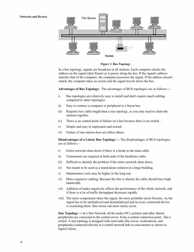
Figure 1: Bus Topology
In a bus topology, signals are broadcast to all stations. Each computer checks the
address on the signal (data frame) as it passes along the bus. If the signal's address
matches that of the computer, the computer processes the signal. If the address doesn't
match, the computer takes no action and the signal travels down the bus.
Advantages of Bus Topology: The advantages of BUS topologies are as follows: --
i) Bus topologies are relatively easy to install and don't require much cabling
compared to other topologies.
ii) Easy to connect a computer or peripheral to a linear bus.
iii) Requires less cable length than a star topology, as you only need to chain the
stations together.
iv) There is no central point of failure on a bus because there is no switch. .
v) Simple and easy to implement and extend.
vi) Failure of one station does not affect others.
Disadvantages of a Linear Bus Topology: -- The disadvantages of BUS topologies
are as follows: --
i) Entire network shuts down if there is a break in the main cable.
ii) Terminators are required at both ends of the backbone cable.
iii) Difficult to identify the problem if the entire network shuts down.
iv) Not meant to be used as a stand-alone solution in a large building.
v) Maintenance costs may be higher in the long run.
vi) More expensive cabling: Because the line is shared, the cable should have high
bandwidth.
vii) Addition of nodes negatively affects the performance of the whole network, and
if there is a lot of traffic throughput decreases rapidly.
viii) The more components share the signal, the more probable errors become. As the
signal has to be multiplexed and demultiplexed and as every connected device
is examining them. thus errors can more easily occur.
Star Topology: -- In a Star Network, all the nodes (PCs, printers and other shared
peripherals) are connected to the central server. It has a central connection point - like a
switch. A star topology is designed with each node (file server, workstations, and
peripherals) connected directly to a central network hub or concentrator as shown in
figure2 below.

9
Network Classifications
and Topologies
Figure 2: Star Topology
All traffic emanates from the switch of the star. Data on a star network passes through
the switch or concentrator before continuing to its destination. The switch or
concentrator manages and controls all functions of the network. It also acts as a repeater
for the data flow. This configuration is common with twisted pair cable; however, it can
also be used with coaxial cable or fiber optic cable. The switch offers a common
connection for all stations on the network. Each station has its own direct cable
connection to the switch.
Advantages of a Star Topology: -- The advantages of star topologies are as follows:
i) Easy to add new stations as each station has its own direct cable connection to
the switch. If a cable is cut, it only affects the computer that was attached to it.
ii) It can accommodate different wiring. It can be installed using twisted pair,
coaxial cable or fiber optic cable.
iii) Since all information in a star topology goes through a central point star,
topologies are easy to troubleshoot. A star can simplify troubleshooting because
stations can be disconnected from the switch one at a time until the problem is
isolated.
iv) The main advantage is that one malfunctioning node does not affect the rest of
the network.
Disadvantages of a Star Topology: --The advantages of star topologies are as
follows:-
i) Depending on where the switches are located, star networks can require more
cable length than a linear topology.
ii) If the switch / concentrator/switches fail, nodes attached are disabled.
iii) More expensive than linear bus topologies because of the cost of the switches.
Ring Topology: --All the nodes in a ring network are connected in a closed circle of
cable as shown in figure 3. Messages that are transmitted travel around the ring until
they reach the computer that they are addressed to. The signal being transmitted is
refreshed by each node in the ring between the sender and receiver. In a ring network,
every device has exactly two neighbors for communication purposes.

10
Networks and Devices
Figure 3: Ring Topology
All messages travel through a ring in the same direction. There are no terminated ends to
the cable; the signal travels around the circle and terminated by the source.
Under the ring concept, a chance is given to each node sequentially via a "token" from
one station to the next. When a station wants to transmit data, it "grabs" the token,
attaches data and an address to it, and then sends it around the ring. The token travels
along the ring until it reaches the destination. The receiving computer acknowledges
receipt by stamping incoming message and passes it to the sender. The sender then
releases the token to be used by another computer.
Each station in the ring has equal access but only one station can talk at a time. In
contrast to the 'passive' topology of the bus, the ring employs an 'active' topology. Each
station repeats or 'boosts' the signal before passing it on to the next station. Rings are
normally implemented using twisted pair or fiber-optic cable.
Advantages of Ring Topology: -- The advantages of ring topologies are as follows: -
i) Growth of system has minimal impact on performance. The ring networks can
be larger than bus or star because each node regenerates the signal.
ii) Degrade nicely under high utilization. Everybody gets to talk."
iii) Fault tolerance builds into the design (can bypass damaged nodes).
iv) Data packets travel at a greater speed.
Disadvantages of Ring Topology: -- The disadvantages of ring topologies are as
follows: -
i) Expensive topology.
ii) Failure of one interface may impact others. A failure in any cable or device
breaks the loop and will take down the entire segment.
iii) It is complex to implement and to extend the network; you must break the
iv) Ring (which brings the network down). If any device is added to or removed
from the ring, the ring is broken and the segment fails.
Mesh Topology: -- In the topologies shown in figure 4, there is only one possible path
from one node to another node. If any cable in the path is broken, the nodes cannot
communicate. In a mesh topology, every device has a dedicated point-to point link to
every other device. Such a network is called complete because between any two devices
there is a special link; one could not add any non- redundant links.

11
Network Classifications
and Topologies
Figure 4: Mesh Topology
Mesh topology uses lots of cables to connect every node with every other node. It is very
expensive to wire up, but if any cable fails, there are many other ways for two nodes to
communicate. In mesh topology if we have to connect ‘n’ computers then we need
n*(n-1)/2 cables/connections and each computer must have (n-1) Ethernet cards.
Advantages of Mesh Topology: -- The advantages of mesh topology are as follows:-
i) Redundant links between devices.
ii) Good security: If the line is not tapped only the intended recipient can see the
data.
iii) Reliability: Increasing network traffic does not affect the speed of other
connections.
iv) Easy fault identification and isolation, an unusable link does not incapacitate
the entire system
Disadvantages of Mesh Topology: -- The disadvantages of mesh topology are as
follows: -
i) Each node must have an interface for every other device.
ii) Large amounts of cable for many devices to be connected in a mesh
environment. A mesh topology for n devices needs n (n - 1) connections. It is
therefore hard to install and expensive because of the extensive cabling.
iii) Unless each station sends to every other station frequently, bandwidth is
wasted. (Links that are not being used).
iv) Another disadvantage is that there is only limited of I/O-ports in a computer, but
every connection needs one.
Tree Topology: -- The tree topology also known as the 'Hierarchical topology'. The tree
topology is a combination of bus and star topologies. It consists of groups of star-
configured workstations connected to' a linear bus backbone cable. Tree topologies
allow for the expansion of an existing network and enable to configure a network to
meet their needs. They are very common in larger networks. Figure 5 given below shows
a typical tree topology.

12
Networks and Devices
Figure 5: Tree Topology
For example, a file server is connected to a 24-port switch. A cable goes from the switch
to a computer room where it connects to another switch. Many cables pass from this
switch to the computers in the computer room. The node at the highest point in the
hierarchy usually a file server-controls the network.
Advantages of a Tree Topology: -- The advantages of tree topology are as follows:-
i) Point-to-point wiring for individual segments.
ii) Supported by several hardware and software vendors.
Disadvantages of a Tree Topology: -- The disadvantages of tree topology are as
follows:-
i) Overall length of each segment is limited by the type of cabling used.
ii) If the backbone line breaks, the entire segment goes down.
iii) More difficult to configure and wire than other topologies.
Considerations When Choosing a Topology
The considerations while choosing topologies are as follows: --
i) Cost: A linear bus network may be the least expensive way to install a network;
you do not have to purchase concentrators
ii) Length of cable needed: The linear bus network uses shorter lengths of cable.
iii) Future growth: With a star topology, expanding a network is easily done by
adding another switch.
iv) Cable type: The most common cable is unshielded twisted pair, which is most
often used with bus, star topologies.
1.4 LAN /MAC ACCESS METHODS
Goals of MAC: Medium Access Control techniques are designed with the following
goals in mind.
• Initialisation: The technique enables network stations, upon power-up, to enter
the state required for operation.
• Fairness: The technique should treat each station fairly in terms of the time it is
made to wait until it gains entry to the network, access time and the time it is
allowed to spend for transmission.

13
Network Classifications
and Topologies • Priority: In managing access and communications time, the technique should
be able to give priority to some stations over other stations to facilitate different
type of services needed.
• Limitations to one station: The techniques should allow transmission by one
station at a time.
• Receipt: The technique should ensure that message packets are actually
received (no lost packets) and delivered only once (no duplicate packets), and
are received in the proper order.
• Error Limitation: The method should be capable of encompassing an
appropriate error detection scheme.
• Recovery: If two packets collide (are present on the network at the same time),
or if notice of a collision appears, the method should be able to recover, i.e. be
able to halt all the transmissions and select one station to retransmit.
• Re-configurability: The technique should enable a network to accommodate
the addition or deletion of a station with no more than a noise transient from
which the network station can recover.
• Compatibility: The technique should accommodate equipment from all
vendors who build to its specification.
• Robustness: The technique should enable a network to confine operating in
spite of a failure of one or several stations.
The MAC (Medium Access Control) techniques can be broadly divided into four
categories; Contention-based, Round-Robin, Reservation-based and. Channelization-
based. Under these four broad categories there are specific techniques, as shown in
Figure 6 below:
Figure 6: Classification of Medium Access Control techniques
There are different of methods used as access protocols in LANs, major techniques
being token passing and CSMA/CD. Token passing can be used with ring or bus
topologies. Token passing scheme is an access protocol that permits a terminal to
transmit only on receipt of a special circulating bit sequence. CSMA/CD (carrier sense
multiple access, with collision detected) is used with bus and some star topologies.
Random Access (Contention-based Approaches) : Round-Robin techniques work
efficiently when majority of the stations have data to send most of the time. But, in
situations where only a few nodes have data to send for brief periods of time, Round-
Robin techniques are unsuitable. Contention techniques are suitable for bursty nature of
14
Networks and Devices
traffic. In contention techniques, there is no centralised control and when a node has
data to send, it contends for gaining control of the medium. The principle advantage of
contention techniques is their simplicity. They can be easily implemented in each node.
The techniques work efficiently under light to moderate load, but performance rapidly
falls under heavy load.
In the 1970s, Norman Abramson and his colleagues at the University of Hawaii devised
a new and elegant method to solve the channel allocation problem. Their work has been
extended by many researchers since then (Abramson, 1985). Although Abramson's
work, called the ALOHA system, used ground-based radio broadcasting, the basic idea
is applicable to any system in which uncoordinated users are competing for the use of a
single shared channel.
ALOHA have two versions pure and slotted. They differ with respect to whether time is
divided into discrete slots into which all frames must fit. Pure ALOHA does not require
global time synchronization; slotted ALOHA does. These pure and slotted ALOHA
schemes will be discussed further in this block.
CSMA/CD: CSMA/CD stands for Carrier Sense Multiple Access with Collision
Detection. It refers to the means of media access, or deciding "who gets to talk" in an
Ethernet network. In detailed mechanisms of CSMA/CD will be discussed further in this
block.
Round Robin Techniques: In Round Robin techniques, each and every node is given
the chance to send or transmit by rotation. When a node gets its turn to send, it may
either decline to send, or it may send if it has got data to send. After getting the
opportunity to send, it must relinquish its turn after some maximum period of time. The
right to send then passes to the next node based on a predetermined logical sequence.
The right to send may be controlled in a centralised or distributed manner. Polling is an
example of centralised control and token passing is an example of distributed control.
i) Polling: The mechanism of polling is similar to the roll-call performed in a
classroom. Just like the teacher, a controller sends a message to each node in
turn. The message contains the address of the node being selected for granting
access. Although all nodes receive the message, only the addressed node
responds and then it sends data, if any. If there is no data, usually a “poll reject”
message is sent back. In this way, each node is interrogated in a round-robin
fashion, one after the other, for granting access to the medium. The first node is
again polled when the controller finishes with the remaining codes. The polling
scheme has the flexibility of either giving equal access to all the nodes, or some
nodes may be given higher priority than others. In other words, priority of
access can be easily implemented.
ii) Token Passing: In token passing scheme, all stations are logically connected in
the form of a ring and control of the access to the medium is performed using a
token. A token is a special bit pattern or a small packet, usually several bits in
length, which circulate from node to node. Token passing can be used with both
broadcast (token bus) and sequentially connected (token ring) type of networks
with some variation.
15
Network Classifications
and Topologies
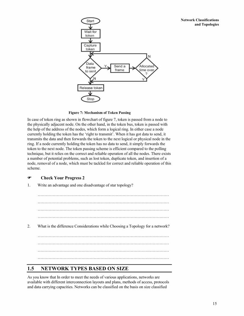
Figure 7: Mechanism of Token Passing
In case of token ring as shown in flowchart of figure 7, token is passed from a node to
the physically adjacent node. On the other hand, in the token bus, token is passed with
the help of the address of the nodes, which form a logical ring. In either case a node
currently holding the token has the ‘right to transmit’. When it has got data to send, it
transmits the data and then forwards the token to the next logical or physical node in the
ring. If a node currently holding the token has no data to send, it simply forwards the
token to the next node. The token passing scheme is efficient compared to the polling
technique, but it relies on the correct and reliable operation of all the nodes. There exists
a number of potential problems, such as lost token, duplicate token, and insertion of a
node, removal of a node, which must be tackled for correct and reliable operation of this
scheme.
���� Check Your Progress 2
1. Write an advantage and one disadvantage of star topology?
……………………………………………………………………………………
……………………………………………………………………………………
……………………………………………………………………………………
……………………………………………………………………………………
2. What is the difference Considerations while Choosing a Topology for a network?
……………………………………………………………………………………
……………………………………………………………………………………
……………………………………………………………………………………
……………………………………………………………………………………
1.5 NETWORK TYPES BASED ON SIZE
As you know that In order to meet the needs of various applications, networks are
available with different interconnection layouts and plans, methods of access, protocols
and data carrying capacities. Networks can be classified on the basis on size classified

16
Networks and Devices
are following. You have already studied the brief about LAN, MAN and WAN in the
beginning of this unit. Now, in this section lets us again discuss them further.
Personal area network (PAN)
1. Local area network (LAN)
2. Metropolitan area network (MAN)
3. Wide area network (WAN)
1. PAN: A personal area network (PAN) is a computer network organized
around an individual person. Personal area networks typically involve
network of a mobile computer, a cell phone and/or a handheld computing
device such as a PDA. You can use these networks to transfer files
including email and calendar appointments, digital photos and music.
Personal area networks can be constructed with cables or wirelessly. USB
and FireWire technologies often link together a wired PAN while wireless
PANs typically use Bluetooth or sometimes infrared connections.
Bluetooth PANs are also called piconets. Personal area networks
generally cover a range of less than 10 meters (about 30 feet).
2. LAN: A local area network (LAN) supplies networking capability to a
group of computers in close proximity to each other such as in an office
building, a school, or a home. A LAN is useful for sharing resources like
files, printers, games or other applications. A LAN in turn often connects
to other LANs, and to the Internet or other WAN. Most local area
networks are built with relatively inexpensive hardware such as Ethernet
cables, network adapters, and hubs. Wireless LAN and other more
advanced LAN hardware options also exist. Specialized operating system
software may be used to configure a local area network. For example,
most flavors of Microsoft Windows provide a software package called
Internet Connection Sharing (ICS) that supports controlled access to LAN
resources.
3. MAN: A Metropolitan Area Network (MAN) is a network that is
designed to cover an entire city. As we have seen, organizations create
smaller networks called as Local Area Networks (LANs). LANs are
privately owned networks within the premises of an organization.
However, suppose that an organization wants to connect the computers in
its three city offices to each other. In such a case, the organization cannot
obviously lay a private network all around the city. WAN: A Wide Area
Network (WAN) is huge compared to a LAN or a MAN. A WAN spans
across city, state, country or even continent boundaries. For instance, a
WAN could be made up of a LAN in India, another LAN in the US and a
third LAN in Japan, all connected to each other to form a big network of
networks. The technical specifications of WAN differ from that of a
LAN, although in principle, a WAN looks like a very big LAN.
1.6 FUNCTIONAL CLASSIFICATION OF NETWORKS
On the basis of functional relationship network is classified as follows:
1. Peer-to-peer
2. Client-server
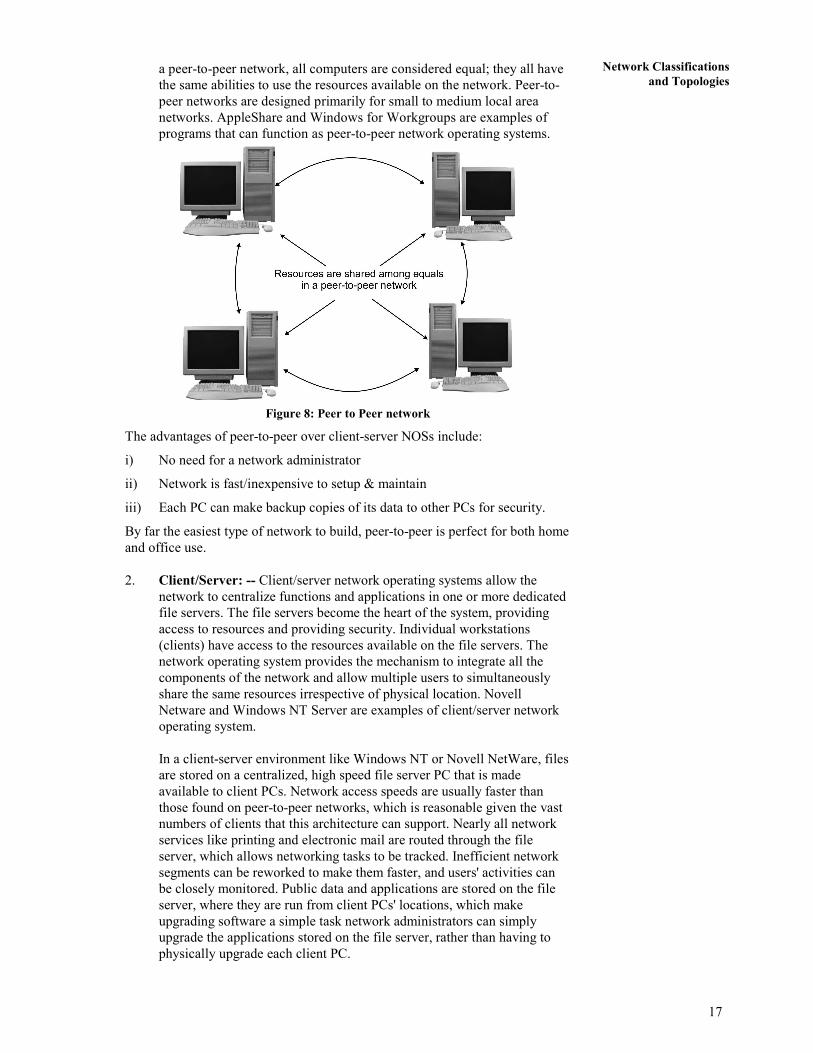
1. Peer-to-Peer: -- Peer-to-peer network operating systems allow users to
share resources and files located on their computers and to access shared
resources found on other computers. However, they do not have a file
server or a centralized management source (See figure 8 given below). In
17
Network Classifications
and Topologies a peer-to-peer network, all computers are considered equal; they all have
the same abilities to use the resources available on the network. Peer-to-
peer networks are designed primarily for small to medium local area
networks. AppleShare and Windows for Workgroups are examples of
programs that can function as peer-to-peer network operating systems.
Figure 8: Peer to Peer network
The advantages of peer-to-peer over client-server NOSs include:
i) No need for a network administrator
ii) Network is fast/inexpensive to setup & maintain
iii) Each PC can make backup copies of its data to other PCs for security.
By far the easiest type of network to build, peer-to-peer is perfect for both home
and office use.
2. Client/Server: -- Client/server network operating systems allow the
network to centralize functions and applications in one or more dedicated
file servers. The file servers become the heart of the system, providing
access to resources and providing security. Individual workstations
(clients) have access to the resources available on the file servers. The
network operating system provides the mechanism to integrate all the
components of the network and allow multiple users to simultaneously
share the same resources irrespective of physical location. Novell
Netware and Windows NT Server are examples of client/server network
operating system.
In a client-server environment like Windows NT or Novell NetWare, files
are stored on a centralized, high speed file server PC that is made
available to client PCs. Network access speeds are usually faster than
those found on peer-to-peer networks, which is reasonable given the vast
numbers of clients that this architecture can support. Nearly all network
services like printing and electronic mail are routed through the file
server, which allows networking tasks to be tracked. Inefficient network
segments can be reworked to make them faster, and users' activities can
be closely monitored. Public data and applications are stored on the file
server, where they are run from client PCs' locations, which make
upgrading software a simple task network administrators can simply
upgrade the applications stored on the file server, rather than having to
physically upgrade each client PC.

18
Networks and Devices
1.7 WAN TOPOLOGIES
A wide area network (WAN) is a network connecting geographically distinct
locations, which may or may not belong to the same organization. WAN topologies
use both LAN add enterprise-wide topologies as building blocks, but add more
complexity because of the distance they must cover, the larger number of users they
serve, and the heavy traffic they often handle. For example, although a simple ring
topology may suffice for a small office with 10 users, it does not scale well and
therefore cannot serve 1000 users. The particular WAN topology you choose will
depend on the number of sites you must connect, the distance between the sites, and
any existing infrastructure.
WAN Ring Topology: In a ring WAN topology, each site is connected to two other
sites so that the entire WAN forms a ring pattern. This architecture is similar to the
ring LAN topology, except that a ring WAN topology connects locations rather than
local nodes. The advantages of a ring WAN over a peer-to-peer WAN are twofold: a
single cable problem will not affect the entire network, and routers at any site can
redirect data to another route if one route becomes too busy. On the other hand,
expanding a peer-to-peer WAN because it requires at least one additional link. For
those reasons, WANs that use the ring topology are only practical for connecting
fewer than four or five locations.
WAN Star Topology: The star WAN topology mimics the arrangement of a star
LAN. A single site acts as the central connection point for several other points. This
arrangement provides separate routes for data between any two sites. As a result, star
WANs are more reliable than the peer-to-peer or ring WANs. As a general rule,
reliability increases with the number of potential routes data can follow. Another
advantage of a star WAN is that when all of its dedicated circuits are functioning, a
star WAN provides shorter data paths between any two sites.
WAN Mesh Topology: Like an enterprise-wide mesh, a mesh WAN topology
incorporates many directly interconnected nodes--in this case, geographical locations.
Because every site is interconnected, data can travel directly from its origin to its
destination. If one connection suffers a problem, routers can redirect data easily and
quickly. Mesh WANs are the most fault-tolerant type of WAN configuration because
they provide multiple routes for data to follow between any two points.
One drawback to a mesh WAN is the cost; connecting every node on a network to
every other entails leasing a large number of dedicated circuits. With larger WANs,
the expense can become enormous. To reduce costs, you might choose to implement a
partial mesh, in which critical WAN nodes are directly interconnected and secondary
nodes are connected through star or ring topologies. Partial-mesh WANs are more
practical and therefore more common in today's business world, than full-mesh
WANs.
1.8 WAN ACCESS METHODS
WAN access methods are as follows:
1. Lease Line: A permanent telephone connection between two points set up by a
telecommunications common carrier. Typically, leased lines are used by
businesses to connect geographically distant offices. Unlike normal dial-up
connections, a leased line is always active. The fee for the connection is a fixed
monthly rate. The primary factors affecting the monthly fee are distance
between end points and the speed of the circuit. Because the connection doesn't
carry anybody else's communications, the carrier can assure a given level of
quality.

19
Network Classifications
and Topologies For example, a T-1 channel is a type of leased line that provides a maximum
transmission speed of 1.544 Mbps. You can divide the connection into different
lines for data and voice communication or use the channel for one high speed
data circuit. Dividing the connection is called multiplexing.
Increasingly, leased lines are being used by companies, and even individuals,
for Internet access because they afford faster data transfer rates and are cost-
effective if the Internet is used heavily.
2. Packet Switching: --Packet switching is used to overcome from limitations of
circuit switching, packet switching has emerged as the standard switching
technology for computer-to-computer communications, and therefore, used by
most of the communication protocols such as X.25, TCP/IP, Frame Relay,
ATM, etc. Unlike in a circuit switching, in packet switching, data to be sent is
divided into and then sent as discrete blocks, called packets, which are of
potentially variable length. The underlying network mandates the maximum
size of data called packet size or packet length-that can be transmitted at a given
time. Each packet contains data to be transferred, and also the control
information such as the sender's address and the destination's address. Packets
also help in recovering from erroneous transmission quicker and more easily.
This is because, in this case, only the packers in error need to be retransmitted.
3. ISDN: Integrated Services Digital Network (ISDN) was developed by ITU- Tin
1976. It is a set of protocols that combines digital telephony and data transport
services. The whole idea is to digitize the telephone network to permit the
transmission of audio, video, and text over existing telephone lines.
ISDN is an effort to standardize subscriber services, provide user/network inter-
faces, and facilitate the internetworking capabilities of existing voice and data
networks. The goal of ISDN is to form a wide area network that provides
universal end-to end connectivity over digital media. This can be done by
integrating all of the separate transmission services into one without adding
new links or subscriber lines.
DSL: Digital subscriber line (DSL) is a family of technologies that provide
Internet access by transmitting digital data over the wires of a local telephone
network. It is a high-speed Internet service like cable Internet. DSL provides
high-speed networking over ordinary phone lines using broadband modem
technology. DSL technology allows Internet and telephone service to work over
the same phone line without requiring customers to disconnect either their voice
or Internet connections. DSL technology theoretically supports data rates of
8.448 Mbps, although typical rates are 1.544 Mbps or lower. DSL Internet
services are used primarily in homes and small businesses. DSL Internet service
only works over a limited physical distance and remains unavailable in many
areas where the local telephone infrastructure does not support DSL
technology.
���� Check Your Progress 3
1. Write the advantage of peer-to-peer over client-server.
……………………………………………………………………………………
……………………………………………………………………………………
……………………………………………………………………………………
……………………………………………………………………………………
20
Networks and Devices
2. List any three WAN access methods.
……………………………………………………………………………………
……………………………………………………………………………………
……………………………………………………………………………………
1.9 SUMMARY
A communication system that supports many users is called a network. In a network
many computers are connected to each other by various topologies like star, ring,
complete, interconnected or irregular. Depending on the area of coverage a network
can be classified as LAN, MAN or WAN. A network is required for better utilisation
of expensive resources, sharing information, collaboration among different groups,
multimedia communication and video conferencing.
The two different types of networking models OSI and TCP/IP are existing. The
difference between these models was discussed in detail.
1.10 REFERENCES/FURTHER READING
1. Computer Networks, A. S. Tanenbaum 4th Edition, Practice Hall of India, New
Delhi. 2003.
2. Introduction to Data Communication & Networking, 3rd
Edition, Behrouz
Forouzan, Tata McGraw Hill.
3. Computer Networking, J.F. Kurose & K.W. Ross, A Top Down Approach
Featuring the Internet, Pearson Edition, 2003.
4. Communications Networks, Leon Garcia, and Widjaja, Tata McGraw Hill,
2000.
5. Data and Computer Communications, Willian Stallings, 6th Edition, Pearson
Education, New Delhi.
6. www.wikipedia.org
7. Larry L. Peterson, Computer Networks: A Systems Approach, 3rd Edition (The
Morgan Kaufmann Series in Networking).
1.11 SOLUTIONS/ANSWERS
���� Check Your Progress 1
1. There are basically two types of networks:
i) Point to point network or switched networks
ii) Broadcast Networks.
2. Broadcasting refers to addressing a packet to all destinations in a network whereas
multicasting refers to addressing a packet to a subset of the entire network.
���� Check Your Progress 2
1. Advantages of a Star Topology: -- The advantages of star topologies are as
follows:
i) Easy to add new stations as each station has its own direct cable

21
Network Classifications
and Topologies connection to the switch. If a cable is cut, it only affects the computer that
was attached to it.
ii) It can accommodate different wiring. It can be installed using twisted
pair, coaxial cable or fiber optic cable.
Disadvantages of a Star Topology: --The advantages of star topologies are as
follows:-
i) Depending on where the switches are located, star networks can require
more cable length than a linear topology.
ii) If the switch / concentrator/switches fail, nodes attached are disabled.
2. The considerations while choosing topologies are as follows: --
i) Cost: A linear bus network may be the least expensive way to install a
network; you do not have to purchase concentrators
ii) Length of cable needed: The linear bus network uses shorter lengths of
cable.
iii) Future growth: With a star topology, expanding a network is easily done
by adding another switch.
iv) Cable type: The most common cable is unshielded twisted pair, which is
most often used with bus, star topologies.
���� Check Your Progress 3
1. The advantages of peer-to-peer over client-server based networks are:
i) No need for a network administrator
ii) Network is fast/inexpensive to setup & maintain
iii) Each PC can make backup copies of its data to other PCs for security.
By far the easiest type of network to build, peer-to-peer is perfect for both home
and office use.
2. WAN access methods are as follows:
i) Packet Switching: --Packet switching is used to overcome from
limitations of circuit switching, packet switching has emerged as the
standard switching technology for computer-to-computer
communications, and therefore, used by most of the communication
protocols such as X.25, TCP/IP, Frame Relay, ATM, etc.
ii) Lease Line: A permanent telephone connection between two points set
up by a telecommunications common carrier.
iii) ISDN: Integrated Services Digital Network (ISDN) was developed by
ITU- Tin 1976. It is a set of protocols that combines digital telephony and
data transport services.
iv) DSL: Digital subscriber line (DSL) is a family of technologies that
provide Internet access by transmitting digital data over the wires of a
local telephone network.

22
Networks and Devices
UNIT 2 OSI AND TCP/IP MODELS
Structure Page Nos
2.0 Introduction 22
2.1 Objectives 22
2.2 OSI Reference Model 23 2.2.1 Layers in the OSI model
2.2.2 Layer 1: the physical layer
2.2.3 Layer 2: the data-link layer
2.2.4 Layer 3: the network layer
2.2.5 Layer 4: the transport layer
2.2.6 Layer 5: the session layer
2.2.7 Layer 6: the presentation layer
2.2.8 Layer 7: the application layer
2.3 TCP/IP Model 28 2.3.1 Layers in the TCP/IP model
2.3.2 TCP/IP application layer
2.3.3 TCP/IP transport layer
2.3.4 TCP/IP internet layer
2.3.5 TCP/IP network access layer
2.4 Comparison of OSI and TCP/IP Models 31
2.5 TCP/IP Protocols 32 2.5.1 Application layer protocols
2.5.2 Transport layer protocols
2.5.3 Internet layer protocols
2.6 Summary 38
2.7 References/Further Readings 38
2.8 Solutions/Answers 39
2.0 INTRODUCTION
In order for a computer to send information to another computer, and for that
computer to receive and understand the information, there has to exist a set of rules or
standards for this communication process. These standards ensure that varying
devices and products can communicate with each other over any network. This set of
standards is called a network reference model. There are a variety of networked
models currently being implemented. However, in this unit, the focus will be on the
OSI and TCP/IP models.
2.1 OBJECTIVES
After going through this unit, you should be able to know:
• The seven layers of OSI reference model
• Understand each layer of OSI model
• Functions of each layer of OSI model
• Understanding of TCP/IP model and its four Layers
• Detail Description of protocol used in each layer
• Similarities of OSI and TCP/IP
2.2 OSI REFERNCE MODEL
In 1983, the International Standards Organization (ISO) developed a model called
Open Systems Interconnection (OSI) which is a standard reference model for

23
OSI and TCP/IP Models communication between two end users in a network. The model is used in developing
products and understanding networks. It is a prescription of characterizing and
standardizing the functions of a communications system in terms of abstraction layers.
Similar communication functions are grouped into logical layers. A layer serves the
layer above it and is served by the layer below it.
2.2.1 Layers in the OSI Model
OSI divides Telecommunications into Seven Layers as shown below in the Figure 1
given below. Each layer is responsible for a particular aspect of data communication.
For example, one layer may be responsible for establishing connections between
devices, while another layer may be responsible for error checking during transfer.
The layers of the OSI model are divided into two groups: the upper layers and lower
layers. The upper layers (Host layers) focus on user applications and how files are
represented on the computers prior to transport. The lower layers (Media Layers)
concentrate on how the communication across a network actually occurs. Each layer
has a set of functions that are to be performed by a specific protocol(s). The OSI
reference model has a protocol suit for all of its layers.
In computing, a protocol is a convention or standard that controls or enables the
connection, communication, and data transfer between two computing endpoints. In
its simplest form, a protocol can be defined as the rules governing the syntax,
semantics, and synchronization of communication.
Figure 1: The OSI Model
2.2.2 Layer 1: The Physical Layer
The physical layer, the lowest layer of the OSI model, is concerned with the
transmission and reception of the unstructured raw bit stream over a physical medium.
It describes the electrical/optical, mechanical, and functional interfaces to the physical
medium, and carries the signals for all of the higher layers. It provides:

24
Networks and Devices
• Data encoding: modifies the simple digital signal pattern (1s and 0s) used by
the PC to better accommodate the characteristics of the physical medium, and to
aid in bit and frame synchronization.
• Transmission technique: determines whether the encoded bits will be
transmitted by baseband (digital) or broadband (analog) signaling.
• Physical medium transmission: transmits bits as electrical or optical signals
appropriate for the physical medium, and determines: What physical medium
options can be used? And How many volts/db should be used to represent a
given signal state, using a given physical medium?
2.2.3 Layer 2: The data-link layer
The data link layer provides error-free transfer of data frames from one node to
another over the physical layer, allowing layers above it to assume virtually error-free
transmission over the link. To do this, the data link layer provides:
• Frame Traffic Control: tells the transmitting node to "stop” when no frame
buffers are available.
• Frame Sequencing: transmits/receives frames sequentially.
• Frame Acknowledgment: provides/expects frame acknowledgments. Detects
and recovers from errors that occur in the physical layer by retransmitting non-
acknowledged frames and handling duplicate frame receipt.
• Frame Delimiting: creates and recognizes frame boundaries.
• Link Establishment and Termination: establishes and terminates the logical
link between two nodes.
• Frame Error Checking: checks received frames for integrity.
• Media access management: determines when the node "has the right" to use
the physical medium.
Data Link Sub layers
The Data Link Layer is described in more detail with Media Access Control (MAC)
and Logical Link Control (LLC) sub layers; where LLC is consider as upper data link
layer and MAC as lower data link layer as shown below in the Figure 2.
• Logical Link Control (LLC): The LLC is concerned with managing traffic (flow
and error control) over the physical medium and may also assign sequence
numbers to frames and track acknowledgements. LLC is defined in the IEEE
802.2 specification and supports both connectionless and connection-oriented
services used by higher-layer protocols.
• Media Access Control (MAC): The MAC sub layer controls how a computer on
the network gains access to the data and permission to transmit it.

25
OSI and TCP/IP Models
Figure 2: Data Link Sub-Layers
2.2.4 Layer 3: The Network Layer
The network layer provides the functional and procedural means of transferring
variable length data sequences from a source host on one network to a destination host
on a different network. The network layer performs network routing functions, and
might also perform fragmentation and reassembly, and report delivery errors. Routers
operate at this layer, sending data throughout the extended network and making the
Internet possible.
Functions of the network layer include:
• Connection setup
• Addressing
• Routing
• Security
• Quality of Service
• Fragmentation
The Network Layer identifies computers on a network. Two types of packets are used
at the Network layer; Data packets and Route update packets. Data packets are used to
transport user data through the Internet work. Protocols used to support data traffic
are called routed protocols. Route update packets are used to update neighboring
routers about the network connected to all routers within the internet work. Protocols
that send route updates are called routing protocols. This layer is concerned with two
functions Routing and Fragmentation / Reassembly:
Routing: It is the process of selecting the best paths in a network along which to
send data on physical traffic as shown in Figure 3.
Figure 3: Routing at Network Layer
Fragmentation / Reassembly: if the network layer determines that a next router's
maximum transmission unit (MTU) size is less than the current frame size, a router
can fragment a frame for transmission and re-assembly at the destination station.

26
Networks and Devices
2.2.5 Layer 4: The Transport Layer
The transport layer provides transparent transfer of data between end users, providing
reliable data transfer services to the upper layers. The transport layer controls the
reliability of a given link through flow control, segmentation/de-segmentation, and
error control. This layer manages the end-to-end control (for example, determining
whether all packets have arrived). It ensures complete data transfer. The Basic
Transport Layer Services are:
• Resource Utilization (multiplexing): Multiple applications run on the same
machine but use different ports.
• Connection Management (establishing & terminating): The second major
task of Transport Layer is establishing connection between sender & the
receiver before data transmission starts & terminating the connection once the
data transmission is finished
• Flow Control (Buffering / Windowing): Once the connection has occurred
and transfer is in progress, congestion of the data flow can occur at a
destination for a variety of reasons. Possible options include:
o The destination can become overwhelmed if multiple devices are trying to
send it data at the same time.
o The destination can become overwhelmed if the source is sending faster
than it can physically receive.
The Transport Layer is responsible for providing flow control to alleviate the issue of
congestion in the data transfer. Two main methods for flow control include:
Buffering: Buffering is a form of data flow control regulated by the Transport Layer
as depicted in Figure 4. It is responsible for ensuring that sufficient buffers
(Temporary Memory) are available at the destination for the processing of data and
that the data is transmitted at a rate that does not exceed what the buffer can handle.
Figure 4: Buffering at Work
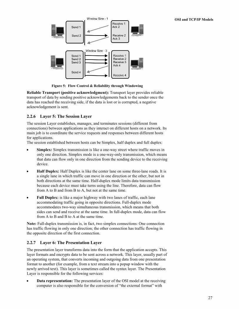
Windowing: Windowing is a flow control scheme in which the source computer
will monitor and make adjustments to the amount of information sent based on
successful, reliable receipt of data segments by the destination computer as shown
in Figure 5. The size of the data transmission, called the "window size", is
negotiated at the time of connection establishment, which is determined by the
amount of memory or buffer that is available.
27
OSI and TCP/IP Models
Figure 5: Flow Control & Reliability through Windowing
Reliable Transport (positive acknowledgment): Transport layer provides reliable
transport of data by sending positive acknowledgements back to the sender once the
data has reached the receiving side, if the data is lost or is corrupted, a negative
acknowledgement is sent.
2.2.6 Layer 5: The Session Layer
The session Layer establishes, manages, and terminates sessions (different from
connections) between applications as they interact on different hosts on a network. Its
main job is to coordinate the service requests and responses between different hosts
for applications.
The session established between hosts can be Simplex, half duplex and full duplex:
• Simplex: Simplex transmission is like a one-way street where traffic moves in
only one direction. Simplex mode is a one-way-only transmission, which means
that data can flow only in one direction from the sending device to the receiving
device.
• Half Duplex: Half Duplex is like the center lane on some three-lane roads. It is
a single lane in which traffic can move in one direction or the other, but not in
both directions at the same time. Half-duplex mode limits data transmission
because each device must take turns using the line. Therefore, data can flow
from A to B and from B to A, but not at the same time.
• Full Duplex: is like a major highway with two lanes of traffic, each lane
accommodating traffic going in opposite directions. Full-duplex mode
accommodates two-way simultaneous transmission, which means that both
sides can send and receive at the same time. In full-duplex mode, data can flow
from A to B and B to A at the same time.
Note: Full-duplex transmission is, in fact, two simplex connections: One connection
has traffic flowing in only one direction; the other connection has traffic flowing in
the opposite direction of the first connection.
2.2.7 Layer 6: The Presentation Layer
The presentation layer transforms data into the form that the application accepts. This
layer formats and encrypts data to be sent across a network. This layer, usually part of
an operating system, that converts incoming and outgoing data from one presentation
format to another (for example, from a text stream into a popup window with the
newly arrived text). This layer is sometimes called the syntax layer. The Presentation
Layer is responsible for the following services:
• Data representation: The presentation layer of the OSI model at the receiving
computer is also responsible for the conversion of “the external format” with
28
Networks and Devices
which data is received from the sending computer to one accepted by the other
layers in the host computer. Data formats include postscript, ASCII, or
BINARY such as EBCDIC (fully Extended Binary Coded Decimal Interchange
Code).
• Data security: Some types of encryption (and decryption) are performed at the
presentation layer. This ensures the security of the data as it travels down the
protocol stack.
• Data compression: Compression (and decompression) may be done at the
presentation layer to improve the throughput of data.
2.2.8 Layer 7: The Application Layer
The application layer is closest to the end user, which means that both the OSI
application layer and the user interact directly with the software application. This
layer interacts with software applications that implement a communicating
component.
The Application Layer is the highest layer in the protocol stack and the layer
responsible for introducing data into the OSI stack. The functions of Application
Layer are:
• Resource sharing and device redirection
• Remote file access
• Remote printer access
• Network management
• Directory services
• Electronic messaging (such as mail) etc
2.3 TCP/IP MODEL
The TCP/IP Model is a specification for computer network protocols created in the
1970s by DARPA, an agency of the United States Department of Defense. It laid the
foundation for ARPANET, which was the world's first wide area network and a
predecessor of the Internet.
2.3.1 Layers in the TCP/IP Model
TCP/IP is generally described as having four 'layers’ or five if we include the bottom
physical layer. The layers near the top are logically closer to the user application,
while those near the bottom are logically closer to the physical transmission of the
data.
2.3.2 TCP/IP Application Layer
TCP/IP application layer protocols provide services to the application software
running on a computer. The application Layer identifies the application running on
the computer through Port Numbers.
The various protocols that are used at the Application Layer are:
• Telnet: Terminal Emulation, Telnet is a program that runs on your computer
and connects your PC to a server on the network. You can then enter commands
through the Telnet program and they will be executed as if you were entering
them directly on the server console. Port Number :23

29
OSI and TCP/IP Models • FTP: File Transfer Protocol, the protocol used for exchanging files over the
Internet. FTP is most commonly used to download a file from a server using the
Internet or to upload a file to a server. Port Number : 20(data port) ,21(control
port)
• HTTP: Hyper Text Transfer Protocol is the underlying protocol used by the
World Wide Web. HTTP defines how messages are formatted and transmitted,
and what actions Web servers and browsers should take in response to various
commands. For example, when we enter a URL in the browser, this actually
sends an HTTP command to the Web server directing it to fetch and transmit
the requested Web page. Port Number :80
• NFS: Network File System, a client/server application that allows all network
users to access shared files stored on computers of different types. Users can
manipulate shared files as if they were stored locally on the user's own hard
disk. Port Number :2049
• SMTP: Simple Mail Transfer Protocol, a protocol for sending e-mail messages
between servers. In addition, SMTP is generally used to send messages from a
mail client to a mail server. Port Number :25
• POP3: Post Office Protocol, a protocol used to retrieve e-mail from a mail
server. Most e-mail applications (sometimes called an e-mail client) use the
POP, although some can use the newer IMAP (Internet Message Access
Protocol)as a replacement for POP3 Port Number :110
• TFTP: Trivial File Transfer Protocol, a simple form of the File Transfer
Protocol (FTP). TFTP provides no security features. It is often used by servers
to boot diskless workstations, X-terminals, and routers. Port Number :69
• DNS: Domain Name System (or Service or Server), an Internet service that
translates domain names into IP addresses. Because domain names are
alphabetic, they're easier to remember. The Internet however, is really based on
IP addresses. Every time you use a domain name, a DNS service must translate
the name into the corresponding IP address. For example, the domain name
www.example.com might translate to 198.105.232.4. Port Number :53
• DHCP: Dynamic Host Configuration Protocol, a protocol for assigning
dynamic IP addresses to devices on a network. With dynamic addressing, a
device can have a different IP address every time it connects to the network.
Dynamic addressing simplifies network administration because the software
keeps track of IP addresses rather than requiring an administrator to manage the
task. Port Number : 67(Server),68(Client)
• BOOTP: Bootstrap Protocol (BOOTP) is utilized by diskless workstations to
gather configuration information from a network server. This enables the
workstation to boot without requiring a hard or floppy disk drive. Port Number :
67(Server),68(Client)
• SNMP: Simple Network Management Protocol, a set of protocols for managing
complex networks. SNMP works by sending messages, called protocol data
units (PDUs), to different parts of a network. Port Number :161
2.3.3 TCP/IP Transport Layer
The protocol layer just below the Application layer is the host-to-host layer
(Transport layer). It is responsible for end-to-end data integrity. Transport Layer
identifies the segments through Socket address (Combination of Port Number & I.P.
address).
The two most important protocols employed at this layer are the

30
Networks and Devices
• Transmission Control Protocol (TCP): TCP provides reliable, full-duplex
connections and reliable service by ensuring that data is retransmitted when
transmission results in an error (end-to-end error detection and correction).
Also, TCP enables hosts to maintain multiple, simultaneous connections.
• User Datagram Protocol (UDP): When error correction is not required, UDP
provides unreliable datagram service (connectionless) that enhances network
throughput at the host-to-host transport layer. It's used primarily for
broadcasting messages over a network.
2.3.4 TCP/IP Internet Layer
The best known TCP/IP protocol at the internetwork layer is the Internet Protocol
(IP), which provides the basic packet delivery service for all TCP/IP networks node
addresses, the IP implements a system of logical host addresses called IP addresses.
The IP addresses are used by the internetwork and higher layers to identify devices
and to perform internetwork routing. IP is used by all protocols in the layers above
and below it to deliver data, which means all TCP/IP data flows through IP when it is
sent and received, regardless of its final destination.
The basic protocols used at the Internet Layer are:
• I.P. (Internet Protocol): It is a protocol used at the internet layer of TCP/IP
model by which data is encapsulated and is sent from one computer to another
on the Internet.
• ARP (Address Resolution Protocol): It is used to map the known I.P. addresses
into Physical address.
• RARP(Reverse Address Resolution Protocol): It is used to map Physical
address into I.P. address
• I.C.M.P.( Internet Control Message Protocol): It is used to send error & control
Messages in the network
• I.G.M.P. (Internet Group Management Protocol): It is a protocol which is used
to form multicast groups in a network to receive multicast messages.
2.3.5 TCP/IP Network Access Layer
The network access layer is the lowest layer in the TCP/IP model. This layer contains
the protocols that the computer uses to deliver data to the other computers and devices
that are attached to the network. The protocols at this layer perform three distinct
functions:
• They define how to use the network to transmit a frame, which is the data unit
passed across the physical connection.
• They exchange data between the computer and the physical network.
• They deliver data between two devices on the same network using the physical
address.
The network access layer includes a large number of protocols. For instance, the
network access layer includes all the variations of Ethernet protocols and other LAN
standards. This layer also includes the popular WAN standards, such as the Point-to-
Point Protocol (PPP) and Frame Relay.

31
OSI and TCP/IP Models 2.4 COMPARISON OF OSI AND TCP/IP MODELS
As it can be seen from the previous pages, there are a number of comparisons, which
can be drawn between the two models as shown below in the Figure 6. This section
will therefore be focusing on highlighting the similarities and differences between the
OSI and TCP/IP models.
Figure 6: OSI Vs TCP/IP
Similarities
The main similarities between the OSI and TCP/IP models include the following:
• They share similar architecture. - Both of the models share a similar
architecture. This can be illustrated by the fact that both of them are
constructed with layers.
• They share a common application layer.- Both of the models share a common
"application layer". However in practice this layer includes different services
depending upon each model.
• Both models have comparable transport and network layers.- This can be
illustrated by the fact that whatever functions are performed between the
presentation and network layer of the OSI model similar functions are
performed at the Transport layer of the TCP/IP model.
• Both models assume that packets are switched.- Basically this means that
individual packets may take differing paths in order to reach the same
destination.
Differences
The main differences between the two models are as follows:
32
Networks and Devices
• TCP/IP Protocols are considered to be standards around which the internet has
developed. The OSI model however is a "generic, protocol- independent
standard."
• TCP/IP combines the presentation and Chapter layer issues into its application
layer.
• TCP/IP combines the OSI data link and physical layers into the network access
layer.
• TCP/IP appears to be a simpler model and this is mainly due to the fact that it
has fewer layers.
• TCP/IP is considered to be a more credible model- This is mainly due to the fact
because TCP/IP protocols are the standards around which the internet was
developed therefore it mainly gains creditability due to this reason. Where as in
contrast networks are not usually built around the OSI model as it is merely
used as a guidance tool.
���� Check Your Progress 1
1. How transport layer of OSI model provide flow control to improve the issue of
congestion in the data transfer?
……………………………………………………………………………………
……………………………………………………………………………………
……………………………………………………………………………………
……………………………………………………………………………………
2. Write the main similarities between the TCP/IP and OSI reference models.
……………………………………………………………………………………
……………………………………………………………………………………
……………………………………………………………………………………
2.5 TCP/IP PROTOCOLS
Transmission Control Protocol (TCP)/Internet Protocol (IP) is a set of protocols
developed to allow computers of all sizes from different vendors, running different
operating systems, to communicate or to share resources across a network. A packet
switching network research project was started by the USA Government in the late
1960s in 1990s, became the most widely used form of computer networking. This
project centered on ARPANET. ARPANET is best-known TCP/IP network. TCP/IP is
the principal UNIX networking protocol and was designed to provide a reliable end-
to-end byte stream over an unreliable internetwork. TCP is a connection-oriented
protocol while IP is a connectionless protocol. TCP supplies logic to give a reliable
connection-oriented protocol above IP. It provides a virtual-circuit that two processes
can use to communicate. IP provides a connectionless and unreliable delivery system
and transfer each datagram independently in the network. UDP is a connectionless
and unreliable protocol running over IP. It adds a checksum to IP for the contents of
the datagram and pass members. In this section, we are going to discuss all the
protocols of TCP/IP in brief.

33
OSI and TCP/IP Models 2.5.1 Application Layer Protocols
The Application layer provides applications the ability to access the services of the
other layers and defines the protocols that applications use to exchange data. There
are many Application layer protocols and new protocols are always being developed.
The major functions of Application Layer are:
• Transfer of file that make up of Web pages
• Interactive file transfer(FTP)
• Transfer of mail messages and attachments
• Logging on remotely to networks hosts
• Resolving host name of an IP address
• Exchanging routing information on an IP internetwork.
• Collecting and exchanging network management information.
The Most common Application Layer Protocols are:
• Telnet (Network Terminal Protocol )
• FTP (File Transfer Protocol)
• SMTP(Simple Mail Transfer Protocol)
• DNS(Domain Name Server)
• RIP(Routing Information Protocol)
• SNMP(Simple Network Management Protocol)
Network Terminal Protocol
The purpose of the Telnet protocol is to provide a fairly general, bi-directional, eight-
bit byte-oriented communications facility. Its primary goal is to allow a standard
method of interfacing terminal devices and terminal-oriented processes to each other.
Telnet not only allows the user to log in to a remote host, it allows that user to execute
commands on that host. Thus, an individual in Los Angeles can Telnet to a machine in
New York and begin running programs on the New York machine just as though the
user were actually in New York.
File Transfer Protocol
FTP (File Transfer Protocol) is the simplest and most secure way to exchange files
over the Internet. Whether you know it or not, you most likely use FTP all the time.
The most common use for FTP is to download files from the Internet. When
downloading a file from the Internet you're actually transferring the file to your
computer from another computer over the Internet. This is why the \T (transfer) is in
FTP. You may not know where the computer is that the file is coming from but you
most likely know its URL or Internet address.
An FTP address looks a lot like an HTTP, or Website, address except it uses the
prefix ftp:// instead of http://.
Example Website address: http://www.ignou.ac.in
Example FTP site address: ftp://www.ignou.ac.in

34
Networks and Devices
Simple Mail Transfer Protocol
SMTP is a relatively simple, text-based protocol, in which one or more recipients of a
message are specified (and in most cases verified to exist) along with the message text
and possibly other encoded objects. The message is then transferred to a remote
server using a procedure of queries and responses between the client and server.
Either an end-user's email client, a.k.a. MUA (Mail User Agent), or a relaying server's
MTA (Mail Transport Agents) can act as an SMTP client.
An email client knows the outgoing mail SMTP server from its configuration. A
relaying server typically determines which SMTP server to connect to by looking up
the MX (Mail eXchange) DNS record for each recipient's domain name (the part of
the email address to the right of the at (@) sign). Conformant MTAs (not all) fall back
to a simple A record in the case of no MX. (Relaying servers can also be configured
to use a smart host.)
The SMTP client initiates a TCP connection to server's port 25 (unless overridden by
configuration). It is quite easy to test an SMTP server using the telnet program.
SMTP is a "push" protocol that does not allow one to "pull" messages from a remote
server on demand. To do this a mail client must use POP3 or IMAP. Another SMTP
server can trigger a delivery in SMTP using ETRN.
HyperText Transfer Protocol
Hypertext Transfer Protocol (HTTP) is a communications protocol for the transfer of
information on the intranet and the World Wide Web. Its original purpose was to
provide a way to publish and retrieve hypertext pages over the Internet.
HTTP is a request/response standard between a client and a server. A client is the
end-user; the server is the web site. The client making an HTTP request - using a web
browser, spider, or other end-user tool - is referred to as the user agent. The
responding server - which stores or creates resources such as HTML files and images
- is called the origin server. In between the user agent and origin server may be
several intermediaries, such as proxies, gateways, and tunnels. HTTP is not
constrained to using TCP/IP and its supporting layers, although this is its most
popular application on the Internet. Indeed HTTP can be "implemented on top of any
other protocol on the Internet, or on other networks. HTTP only presumes a reliable
transport; any protocol that provides such guarantees can be used."
Typically, an HTTP client initiates a request. It establishes a Transmission Control
Protocol (TCP) connection to a particular port on a host (port 80 by default; see List
of TCP and UDP port numbers). An HTTP server listening on that port waits for the
client to send a request message. Upon receiving the request, the server sends back a
status line, such as "HTTP/1.1 200 OK", and a message of its own, the body of which
is perhaps the requested file, an error message, or some other information.
The reason that HTTP uses TCP and not UDP is because much data must be sent for a
webpage, and TCP provides transmission control, presents the data in order, and
provides error correction.
Domain Name Server
The most basic task of DNS is to translate hostnames to IP addresses. In very simple
terms, it can be compared to a phone book. DNS also has other important uses.
Above all, DNS makes it possible to assign Internet names to organizations (or
concerns they represent) independent of the physical routing hierarchy represented by
the numerical IP address. Because of this, hyperlinks and Internet contact information

35
OSI and TCP/IP Models can remain the same, whatever the current IP routing arrangements may be, and can
take a human-readable form (such as "example.com"), which is easier to remember
than the IP address 208.77.188.166. People take advantage of this when they recite
meaningful URLs and e-mail addresses without caring how the machine will actually
locate them.
The Domain Name System distributes the responsibility for assigning domain names
and mapping them to IP networks by allowing an authoritative name server for each
domain to keep track of its own changes, avoiding the need for a central register to be
continually consulted and updated.
Simple Network Management Protocol
Simple Network Management Protocol (SNMP) is a popular protocol for network
management. It is used for collecting information from, and configuring, network
devices, such as servers, printers, hubs, switches, and routers on an Internet Protocol
(IP) network. Using SNMP, you can monitor network performance, audit network
usage, detect network faults or inappropriate access, and in some cases configure
remote devices. SNMP is designed to be deployed on the largest possible number of
network devices, to have minimal impact on the managed nodes, to have minimal
transport requirements, and to continue working when most other network
applications fail.
Network File System
NFS stands for Network File System, a file system developed by Sun Microsystems,
Inc. It is a client/server system that allows users to access files across a network and
treats them as if they resided in a local file directory. For example, if you were using a
computer linked to a second computer via NFS, you could access files on the second
computer as if they resided in a directory on the first computer. This is accomplished
through the processes of exporting (the process by which an NFS server provides
remote clients with access to its files) and mounting (the process by which file
systems are made available to the operating system and the user).
The NFS protocol is designed to be independent of the computer, operating system,
network architecture, and transport protocol. This means that systems using the NFS
service may be manufactured by different vendors, use different operating systems,
and be connected to networks with different architectures. These differences are
transparent to the NFS application, and thus, the user.
2.5.2 Transport Layer Protocols
In the TCP/IP model, the transport layer is responsible for delivering data to the
appropriate application process on the host computers. This involves multiplexing of
data from different application processes, i.e. forming a segment by adding source and
destination port numbers in the header of each transport layer data packet. Together
with the source and destination IP address (from the internet layer), the port numbers
constitutes a network socket, i.e. an identification address of the process-to-process
communication.
The major functions of Transport Layer are:
• It sets up and maintains a Chapter connection between two devices.
• It can provide for the reliable or unreliable delivery of data across the
connection.
• It can implement flow control through ready/not ready signals or Windowing to
ensure that the sender do not overwhelm the receiver with too many segments.

36
Networks and Devices
• It multiplexes the connections, allowing multiple applications to simultaneously
send and receive data through port or socket numbers
The Most common Transport Layer Protocols are:
• T.C.P (Transmission Control Protocol)
• U.D.P (User Datagram Protocol)
Transmission Control Protocol
TCP is a Reliable (guarantees that the data sent across the connection will be
delivered exactly as sent, without missing or duplicate data), Connection oriented (An
application requests a connection, and then uses it for data transfer) protocol on the
transport layer that provides in-order delivery of data and also use buffering and
windowing to implement flow control.
User Datagram Protocol
The UDP is an unreliable connectionless protocol of the transport layer. UDP is
unreliable, means that UDP does not provide mechanisms for error detection and
error correction between the source and the destination. Because of this, UDP utilized
bandwidth more efficiently than TCP. Connectionless, means that a network node can
communicate with another network node using UDP without first negotiating any
kind of handshaking or creating a connection. Because of this, UDP is very efficient
for protocols that send very small amounts of data at irregular intervals.
2.5.3 Internet Layer Protocols
The TCP/IP internet-layer functionality includes transmitting data to and from the
TCP/IP network interface layer, routing data to the correct network and station on the
destination network, and handling packet errors and fragmentation.
Internet Protocol
The Internet Protocol is the building block of the Internet. IP is a connectionless
protocol, means it does not exchange control information (handshake) to provide end-
to-end control of communications flow. It relies on other layers to provide this
function if it is required. IP also relies on other layers to provide error detection and
correction. Because of this IP is sometimes referred to as an unreliable protocol
because it contains no error detection and recovery code. IP can be relied upon to
accurately deliver your data to the connected network, but it doesn't check whether
that data was correctly received.
Its functions include:
• Defining the datagram, which is the basic unit of transmission in the Internet
• Defining the Internet addressing scheme
• Moving data between the Network Access Layer and the Host-to-Host
Transport Layer
• Routing datagrams to remote hosts
• Performing fragmentation and re-assembly of datagrams
Address Resolution Protocol (ARP)
The address resolution protocol is a protocol used by the Internet Protocol (IP),
specifically IPv4 (IP version 4), to map IP network addresses to the hardware
addresses used by a data link protocol as depicted in figure 7. It is used when IPv4 is
used over Ethernet. ARP works on Ethernet networks as follows. Ethernet network
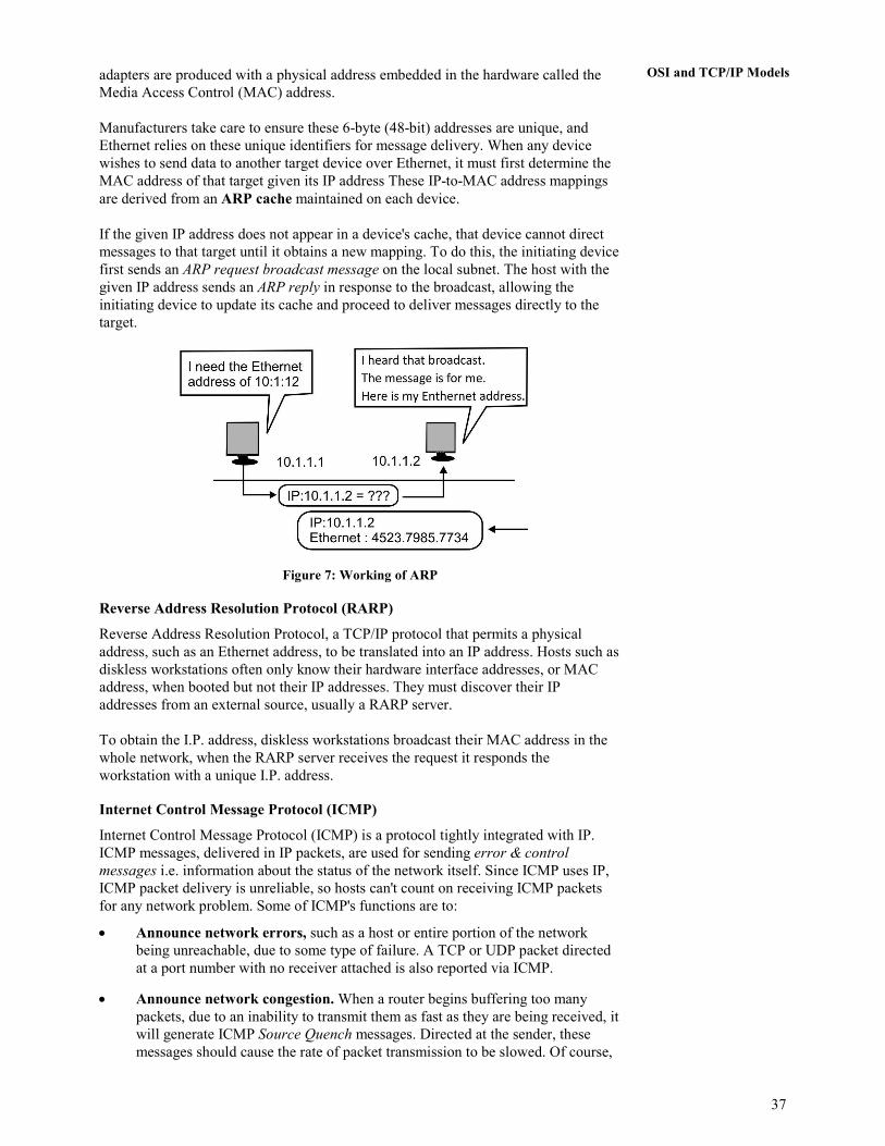
37
OSI and TCP/IP Models adapters are produced with a physical address embedded in the hardware called the
Media Access Control (MAC) address.
Manufacturers take care to ensure these 6-byte (48-bit) addresses are unique, and
Ethernet relies on these unique identifiers for message delivery. When any device
wishes to send data to another target device over Ethernet, it must first determine the
MAC address of that target given its IP address These IP-to-MAC address mappings
are derived from an ARP cache maintained on each device.
If the given IP address does not appear in a device's cache, that device cannot direct
messages to that target until it obtains a new mapping. To do this, the initiating device
first sends an ARP request broadcast message on the local subnet. The host with the
given IP address sends an ARP reply in response to the broadcast, allowing the
initiating device to update its cache and proceed to deliver messages directly to the
target.
Figure 7: Working of ARP
Reverse Address Resolution Protocol (RARP)
Reverse Address Resolution Protocol, a TCP/IP protocol that permits a physical
address, such as an Ethernet address, to be translated into an IP address. Hosts such as
diskless workstations often only know their hardware interface addresses, or MAC
address, when booted but not their IP addresses. They must discover their IP
addresses from an external source, usually a RARP server.
To obtain the I.P. address, diskless workstations broadcast their MAC address in the
whole network, when the RARP server receives the request it responds the
workstation with a unique I.P. address.
Internet Control Message Protocol (ICMP)
Internet Control Message Protocol (ICMP) is a protocol tightly integrated with IP.
ICMP messages, delivered in IP packets, are used for sending error & control
messages i.e. information about the status of the network itself. Since ICMP uses IP,
ICMP packet delivery is unreliable, so hosts can't count on receiving ICMP packets
for any network problem. Some of ICMP's functions are to:
• Announce network errors, such as a host or entire portion of the network
being unreachable, due to some type of failure. A TCP or UDP packet directed
at a port number with no receiver attached is also reported via ICMP.
• Announce network congestion. When a router begins buffering too many
packets, due to an inability to transmit them as fast as they are being received, it
will generate ICMP Source Quench messages. Directed at the sender, these
messages should cause the rate of packet transmission to be slowed. Of course,

38
Networks and Devices
generating too many Source Quench messages would cause even more network
congestion, so they are used sparingly.
• Assist Troubleshooting. ICMP supports an Echo function, which just sends a
packet on a round--trip between two hosts. Ping, a common network
management tool, is based on this feature. Ping will transmit a series of packets,
measuring average round--trip times and computing loss percentages.
• Announce Timeouts. If an IP packet's TTL (Time To Live) field drops to zero,
the router discarding the packet will often generate an ICMP packet announcing
this fact. TraceRoute is a tool which maps network routes by sending packets
with small TTL values and watching the ICMP timeout announcements.
���� Check Your Progress 2
1. How does the HTTP protocol transfer the information on the World Wide Web?
……………………………………………………………………………………
……………………………………………………………………………………
……………………………………………………………………………………
……………………………………………………………………………………
2. Explain the working of Address Resolution Protocol (ARP).
……………………………………………………………………………………
……………………………………………………………………………………
……………………………………………………………………………………
……………………………………………………………………………………
2.6 SUMMARY
This unit began with an introduction to OSI reference model. It gave detailed
information about various layers and functions of each layer of OSI reference model.
The unit covers on understanding of how does the communication happen in a
network. It also covered TCP/IP model. Comparison was made between OSI and
TCP/IP models along with similarities and differences. Some of useful protocols of
each layer of TCP/IP were described.
2.7 REFERENCES/FURTHER READINGS
1. Computer Networks, A. S. Tanenbaum 4th Edition, Practice Hall of India, New
Delhi. 2003.
2. Introduction to Data Communication & Networking, 3rd Edition, Behrouz
Forouzan, Tata McGraw Hill.
3. Computer Networking, J.F. Kurose & K.W. Ross, A Top Down Approach
Featuring the Internet, Pearson Edition, 2003.
4. Communications Networks, Leon Garcia, and Widjaja, Tata McGraw Hill,
2000.
5. www.wikipedia.org
6. Data and Computer Communications, Willian Stallings, 6th Edition, Pearson
Education, New Delhi.

39
OSI and TCP/IP Models 7. Larry L. Peterson, Computer Networks: A Systems Approach, 3rd Edition (The
Morgan Kaufmann Series in Networking).
2.8 SOLUTIONS/ANSWERS
���� Check Your Progress 1
1. The Transport Layer is responsible for providing flow control to alleviate the
issue of congestion in the data transfer. Two main methods for flow control
include:
Buffering: Buffering is a form of data flow control regulated by the Transport
Layer as depicted in Figure 8. It is responsible for ensuring that sufficient
buffers (Temporary Memory) are available at the destination for the processing
of data and that the data is transmitted at a rate that does not exceed what the
buffer can handle.
Figure 8: Buffering at Work
Windowing: Windowing is a flow control scheme in which the source
computer will monitor and make adjustments to the amount of information sent
based on successful, reliable receipt of data segments by the destination
computer as shown in Figure 9. The size of the data transmission, called the
"window size", is negotiated at the time of connection establishment, which is
determined by the amount of memory or buffer that is available.
Figure 9: Flow Control & Reliability through Windowing

40
Networks and Devices
2. The main similarities between the OSI and TCP/IP models include the
following:
• They share similar architecture. - Both of the models share a similar
architecture. This can be illustrated by the fact that both of them are
constructed with layers.
• They share a common application layer.- Both of the models share a
common "application layer". However in practice this layer includes
different services depending upon each model.
• Both models have comparable transport and network layers.- This can be
illustrated by the fact that whatever functions are performed between the
presentation and network layer of the OSI model similar functions are
performed at the Transport layer of the TCP/IP model.
• Both models assume that packets are switched.- Basically this means that
individual packets may take differing paths in order to reach the same
destination.
���� Check Your Progress 2
1. Hypertext Transfer Protocol (HTTP) is a communications protocol for the
transfer of information on the intranet and the World Wide Web. Its original
purpose was to provide a way to publish and retrieve hypertext pages over the
Internet.
HTTP is a request/response standard between a client and a server. A client is
the end-user, the server is the web site. The client making an HTTP request -
using a web browser, spider, or other end-user tool - is referred to as the user
agent. The responding server - which stores or creates resources such as HTML
files and images - is called the origin server. In between the user agent and
origin server may be several intermediaries, such as proxies, gateways, and
tunnels. HTTP is not constrained to using TCP/IP and its supporting layers,
although this is its most popular application on the Internet. Indeed HTTP can
be "implemented on top of any other protocol on the Internet, or on other
networks. HTTP only presumes a reliable transport; any protocol that provides
such guarantees can be used."
Typically, an HTTP client initiates a request. It establishes a Transmission
Control Protocol (TCP) connection to a particular port on a host (port 80 by
default; see List of TCP and UDP port numbers). An HTTP server listening on
that port waits for the client to send a request message. Upon receiving the
request, the server sends back a status line, such as "HTTP/1.1 200 OK", and a
message of its own, the body of which is perhaps the requested file, an error
message, or some other information.
2. The address resolution protocol is a protocol used by the Internet Protocol (IP),
specifically IPv4 (IP version 4), to map IP network addresses to the hardware
addresses used by a data link protocol. It is used when IPv4 is used over
Ethernet. ARP works on Ethernet networks as follows. Ethernet network
adapters are produced with a physical address embedded in the hardware called
the Media Access Control (MAC) address.
Manufacturers take care to ensure these 6-byte (48-bit) addresses are unique,
and Ethernet relies on these unique identifiers for message delivery. When any
device wishes to send data to another target device over Ethernet, it must first
determine the MAC address of that target given its IP address These IP-to-MAC
address mappings are derived from an ARP cache maintained on each device.

41
OSI and TCP/IP Models If the given IP address does not appear in a device's cache, that device cannot
direct messages to that target until it obtains a new mapping. To do this, the
initiating device first sends an ARP request broadcast message on the local
subnet. The host with the given IP address sends an ARP reply in response to
the broadcast, allowing the initiating device to update its cache and proceed to
deliver messages directly to the target.

42
Networks and Devices
UNIT 3 PHYSICAL AND DATA LINK LAYER
Structure Page Nos.
3.0 Introduction 42
3.1 Objectives 42
3.2 Physical and Data Link Layer Services 42
3.3 Error Detection and Correction 44
3.4 Flow and Error Control 48
3.5 Medium Access Control (MAC) Sublayer 51 3.5.1 Contention based media access protocols
3.5.2 Random access protocols
3.5.3 Polling based MAC protocols
3.5.4 IEEE standard 802.3 and Ethernet
3.5.5 IEEE standard 802.4 token bus
3.5.6 IEEE standard 802.5 token ring
3.5.7 Address resolution protocol (ARP)
3.5.8 Reverse address resolution protocol (RARP)
3.6 Summary 55
3.7 References/Further Reading 56
3.7 Solutions/Answers 56
3.0 INTRODUCTION
As you have studied earlier that the physical layer provides an electrical, mechanical,
and functional interface to the transmission medium also the data link layer together
with physical layer provide a data link connection for reliable transfer of data bits over
an imperfect physical connection, between two adjacent nodes. In this unit, we will
study about design of Data Link Layer and its Medium Access Control Sublayer. This
includes various protocols for achieving reliable, efficient communication. It also
covers the study of nature of errors, causes and how they can be detected and corrected.
The MAC sublayer contains protocols which determine what goes next on a multi-
access channel. In the end of this unit you will learn about working of ARP and RARP
protocols.
3.1 OBJECTIVES
After going through this unit, you should be able to:
• Know the services of physical and data link layer
• Understand the concept of framing
• Understand various error handling methods;
• Know the Retransmission Strategies at data link layer
• Understand various flow control methods,
• Understand the working of MAC sub-layer protocols
• Differentiate between CSMA/CD, Polling and Token Passing.
• Understand the working of ARP and RARP
3.2 PHYSICAL AND DATA LINK LAYER SERVICES
To exchange digital information between devices A and B, we require an
interconnecting transmission medium to carry the electrical signals; a standard interface
and the physical layer to convert bits into electrical signals and vice-versa.

`
43
Physical and Data Link
Layer This is an elementary layer below the logical data structures of the higher level functions
in a network. The physical layer deals with transmitting raw bits rather than logical data
packets over a physical network. The bit stream may be grouped into code words or
symbols and converted to an electrical signal that is transmitted over a hardware
transmission medium.
The physical layer provides an electrical, mechanical, and functional interface to the
transmission medium. This layer has certain limitations, for example assume:
• If the electrical signal gets impaired due to the encountered interference with
other signals or electromagnetic waves from external sources, errors may be
introduced in the data bits.
• Errors can also be introduced if the receiving device is not ready for the
incoming signal, hence resulting in the loss of some information.
The data link layer constitutes the second layer of the hierarchical OSI Model. The Data
Link layer together with physical layer provide a data link connection for reliable
transfer of data bits over an imperfect physical connection, between two adjacent nodes.
It accomplishes this task by having the sender break the input data into data frames,
transmit the frames sequentially and process the acknowledgement frames sent back by
the receiver. Remember, like other layers of OSI model this layer also create its own
protocol data unit. Data link layer add some control bits to the protocol data unit
received from network layer and convert into different protocol data unit called frames.
The data link layer creates and recognises frame boundaries too.
Another issue that arises in data link layer is how to keep a fast transmitter from
overflowing a slow receiver in data. The data link layer (Figure 1) incorporates certain
processes, which carry out error control, flow control and the associated link
management functions. The data block along with the control bits is called a frame.
Data link layer (Figure 1) is divided into two sublayers:
Logical Link Control (LLC) concerned with providing a reliable communication part
between two devices. It is also involved with flow control and sequencing. The LLC
is non-architecture-specific and is the same for all IEEE defined LANs.
Medium Access Control (MAC) focuses on methods of sharing a single transmission
medium.
Figure 1: Division of Data Link Layer
The data link layer provides the functional means to transfer data between network
entities and might provide the means to detect and possibly correct errors that may
occur in the physical layer. Following are some of the main services provided by data
Network Layer
LLC
-----------------
MAC
Data Link Layer
Physical Layer

44
Networks and Devices
Link layer:
1. Framing: Encapsulation of network layer data packets into frames, and Frame
synchronization
2. Flow Control: Flow control deals with how to keep the fast sender from
overflowing a slow receiver by buffering and acknowledgement procedures.
This flow control at data link layer is provided in addition to the one provided
on the transport layer.
3. Error detection and correction codes: Various methods used for error-
detection and corrections are – Parity bit, cyclic redundancy check, checksum,
Hamming code, etc.
4. Multiple access protocols for channel-access control
5. Physical addressing (MAC addressing)
6. Quality of Service (QoS) control
3.3 ERROR DETECTION AND CORRECTION
Data that is either transmitted over communication channel or stored in memory is not
completely error free. Transmission Errors may be caused by many reasons like
Signal distortion or attenuation, synchronization problems, distorted channel, etc.
Error detection and corrections are two different but related thing, error detection is
the ability to detect errors but the error correction has an additional feature that
enables identification and correction of the errors. Error detection always precedes
error correction. Both can be achieved by having extra/ redundant/check bits in
addition to data deduce that there is an error.
Error Detection
In the following section parity bit and CRC methods for error detection are discussed.
Parity bits Method
Parity bit method is very simple error detection method in the digital communication.
A binary digit called “parity” is used to indicate whether the number of bits with “1”
in a given set of bits is even or odd. The parity bit is then attached to original bits. In
this method sender adds the parity bit to existing data bits before transmission. At the
receiver side, it checks for the expected parity, if wrong parity found, the received
data is discarded and retransmission is requested. It is a very simple scheme that can
be used to detect single or any other odd/even number of errors in the output.
The parity bit is only suitable for detecting errors; it cannot correct any errors, as
there is no way to determine which particular bit is corrupted. The data must be
discarded entirely, and re-transmitted from scratch. Following are some of the
examples for parity bit methods:
Assume, sender wants to send some bit streams like 001 0101 and 101 0011. If we are
using even parity bit method, we will add “0” with the bit steam having even number
of 1’s otherwise add “1”. So our bit steams will be changed after adding parity bit as
1001 0101and 0101 0011. At the receiver again the number of 1’s are counted in the
original message, if the parity bit is mismatched we can say an error has occurred in
the message. Just like the even parity we may have odd parity bit method. Parity bit
method has many limitations, like it cannot identify the error if more than one bit has
been changed or parity bit itself has been changed during the transmission. Further it
cannot determine which bit position has a problem.

`
45
Physical and Data Link
Layer Cyclic redundancy checks (CRCs)
A cyclic redundancy check (CRC) is an error-detecting code commonly used in digital
networks and storage devices to detect transmission error.
When n-bits of message M(x) is transmitted from sender to receiver, first the n- bits of
message is converted in such a way that when a selected k-bits divisor code G(k) (so-
called generator polynomial) is divided with the x+k-bits message M(x+k) the
remainder is zero.
Than the modified message M(x+k) is sent along with the k-bits divisor code to the
receiver through channel. The receiver will divide this M(x+k) bits with G(k) bits, if
the remainder is zero receiver can say there is no error in the message. Finally the
original message M(x) is separated from the modified message M(x+k).
Let us take assume an example for simple decimal numbers, if you want to send some
number say 10 and divisor code is 3. First, make all legal messages divisible by 3.
For that you need to multiply by 4 to get 40 and add 2 to make it divisible by 3 = 42.
When the data is received and divided by 3, and if there is no remainder, it means
there is no error. If no error, divide by 4 and separate it by 2 to get sent message. If we
receive 43, 44, 41, 40, we can say there is an error. But if 45 is received, we will not
be able to recognize as an error.
We can represent n-bit message as an n-1 degree polynomial; e.g., M=10011010
corresponds to M(x) = x7+ x4 + x3 + x1.
Add k bits of extra data to an n-bit message.
Let k be the degree of some divisor polynomial G(k); e.g., G(k) = x3+ x2 + 1.
Multiply M(x) = x7+ x4 + x3 + x1 by xk; for our example, we get
x10 + x7 + x6 + x4 (10011010000);divide result by G(k) (1101);
Send 10011010000 + 101 = 10011010101, since this must be exactly divisible by
G(k);

46
Networks and Devices
Now, assume if receiver will receive a message with errors, for example receiver has
received a message 10010110101.
Cyclic codes have favorable properties in that they are well suited for detecting burst
errors. CRCs are particularly easy to implement in hardware, and are therefore
commonly used in digital networks and storage devices such as hard disk drives.
Error correction
Mainly, we have two error correction mechanisms one is Automatic Repeat request
and another approach is of using some error correction codes like hamming code.
Automatic Repeat Request
It is an error control method for data transmission that makes use of error-detection
codes, acknowledgment and/or negative acknowledgment messages, and timeouts to
get reliable data transmission. Generally, when the sender does not receive the
acknowledgment before the timeout occurs, it retransmits the frame until it is either
correctly received or the error persists beyond a predetermined number of
retransmissions. Three types of ARQ protocols are Stop-and-wait ARQ, Go-Back-N
ARQ, and Selective Repeat ARQ, these mechanisms we will study further in this unit.

`
47
Physical and Data Link
Layer Error-correcting codes
Any error-correcting code can be used for error correction. An error-correcting code
is a system of adding redundant data, or parity data, to a message, such that it can be
recovered by a receiver even when a number of errors were introduced, either during
the process of transmission, or on storage. Since the receiver does not have to request
the sender for retransmission of the data, a back-channel is not required in forward
error correction, and it is therefore suitable for simplex communication such as
broadcasting. Error-correcting codes are often used in lower layers of OSI like data
link layer and physical layer.
Error-correcting codes can be classified into two type’s convolutional codes which
processed on a bit-by-bit basis and block codes that processed on a block-by-block
basis. Convolutional codes are suitable for implementation in hardware. However,
block codes are error correction in data communication. Hamming code is an example
of block codes. Hamming codes are code words formed by adding redundant check
bits, or parity bits, to a data word. The Hamming distance between two code words is
the number of bits in which two code words differ. For an example 10001001 and
10110001 bytes has a Hamming distance of 3. The minimum Hamming distance for a
code is the smallest Hamming distance between all pairs of words in the code. The
minimum Hamming distance for a code, D(min), determines its error detecting and
error correcting capability. Hamming codes can detect D(min) - 1 errors and correct
(D(min) - 1 )/2 errors.
���� Check Your Progress 1
1. What are the sub-layers of data link layer? Explain.
……………………………………………………………………………………
……………………………………………………………………………………
……………………………………………………………………………………
……………………………………………………………………………………
2. List the services of data link layer.
……………………………………………………………………………………
……………………………………………………………………………………
……………………………………………………………………………………
……………………………………………………………………………………
3. What is parity bit method? Explain its use with the help of an example.
……………………………………………………………………………………
……………………………………………………………………………………
……………………………………………………………………………………
4. Explain the use of Automatic Repeat Request in error correction.
……………………………………………………………………………………
……………………………………………………………………………………
……………………………………………………………………………………

48
Networks and Devices
3.4 FLOW AND ERROR CONTROL
Packets can be lost and/or corrupted during transmission due to Bit level errors and loss
due to congestion. We use checksums to detect bit level errors, and to maintain
reliability into the data transmission stage we use acknowledgements and timeouts to
signal lost or corrupt frame. An acknowledgement (ACK) is a packet sent by one host
in response to a packet it has received. A timeout is a signal that an ACK to a packet that
was sent has not yet been received within a specified timeframe. In this section we will
discuss several retransmission strategies, which are also considered as a flow control
and error control mechanism.
Stop and Wait
The sender allows one message to be transmitted, checked for errors and an appropriate
ACK (Positive Acknowledgement) or NAK (Negative Acknowledgement) returned to
the sending station. No other data messages can be transmitted until the receiving
station sends back a reply, thus the name STOP and WAIT is derived from the
originating station sending a message, stopping further transmission and waiting for a
reply. This scheme is also shown in figure 2 given below.
Figure 2: Stop and Wait Protocol
Its major drawback is the idle line time that results when the stations are in the waiting
period. If the ACK is lost then the sending station retransmits the same message to the
receiver side. The redundant transmission could possibly create a duplicate frame. A
typical approach to solve this problem is the provision for a sequence number in the
header of the message. The receiver can then check for the sequence number to
determine if the message is a duplicate. The Stop and Wait mechanism requires a very
small sequence Number, since only one message is outstanding at any time. The
sending and receiving station only use a one bit alternating sequence of 0 and 1 to
maintain the relationship of the transmitted message and its ACK/NAK status.
Sliding Window
Here data and control frames flow from sender to receiver in a more continuous manner
and several frames can be outstanding at any one time as depicted in figure 3. Allow
multiple outstanding (un-ACKed) frames. Upper bound on un-ACKed frames, called
window. Sender needs to buffer data so that if data is lost, it can be resent.
Receiver needs to buffer data so that if data is received out of order, it can be held until
all packets are received in Flow control Next,
How can we prevent sender overflowing receiver’s buffer?
Receiver tells sender its buffer size during connection setup.
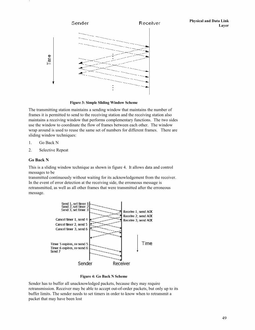
`
49
Physical and Data Link
Layer
Figure 3: Simple Sliding Window Scheme
The transmitting station maintains a sending window that maintains the number of
frames it is permitted to send to the receiving station and the receiving station also
maintains a receiving window that performs complementary functions. The two sides
use the window to coordinate the flow of frames between each other. The window
wrap around is used to reuse the same set of numbers for different frames. There are
sliding window techniques:
1. Go Back N
2. Selective Repeat
Go Back N
This is a sliding window technique as shown in figure 4. It allows data and control
messages to be
transmitted continuously without waiting for its acknowledgement from the receiver.
In the event of error detection at the receiving side, the erroneous message is
retransmitted, as well as all other frames that were transmitted after the erroneous
message.
Figure 4: Go Back N Scheme
Sender has to buffer all unacknowledged packets, because they may require
retransmission. Receiver may be able to accept out-of-order packets, but only up to its
buffer limits. The sender needs to set timers in order to know when to retransmit a
packet that may have been lost

50
Networks and Devices
Selective Repeat
This method provides for a more refined approach. In contrast to the Go back N, the
only messages retransmitted are those for which negative acknowledgement is
received. In this the sending process continues to send a number of frames specified
by a window size even after a frame loss. Unlike Go-Back-N, the receiving process
will continue to accept and acknowledge frames sent after an initial error; this is the
general case of the sliding window protocol with both transmit and receive window
sizes greater than 1.
The receiver process keeps track of the sequence number of the earliest frame it has
not received, and sends that number with every acknowledgement (ACK) it sends. If a
frame from the sender does not reach the receiver, the sender continues to send
subsequent frames until it has emptied its window. The receiver continues to fill its
receiving window with the subsequent frames, replying each time with an ACK
containing the sequence number of the earliest missing frame. Once the sender has
sent all the frames in its window, it re-sends the frame number given by the ACKs,
and then continues where it left off.
Now if we compare Selective Repeat behaves in the same way like Go-Back-N , it
accepts when the receiver receives a frame which is out of sequence, it sends a
SREJ(Selective Reject) message. Sender retransmits only the rejected packet and
continues with other packets. Here in Selective Repeat method the both the
Sender’s and Receiver’s buffer size are equal to the window size.
In the following figure 5, you can see that the difference between Go Back N and
Selective Repeat, because of the buffer frame 5 and Frame 6 are stored and selectively
the reject message is sent only for frame 4 (which was lost in transmission) however
in Go back N the reject message is sent for all 4, 5 and 6 frames.
Figure 5: Comparison between the Go Back N and Selective Repeat method

`
51
Physical and Data Link
Layer Studies reveal that the selective repeat mechanism produces greater throughput than
the Go Back N. Selective Repeat mechanism requires additional logic to maintain the
sequence of the recent message and merge it into the proper place as the queue at the
receiver end.
���� Check Your Progress 2
1. Explain the importance of Sliding Window protocol. Also, List the types of
sliding window techniques.
……………………………………………………………………………………
……………………………………………………………………………………
……………………………………………………………………………………
……………………………………………………………………………………
2. Discuss the working of selective Repeat method. Also, compare it with GO
Back N.
……………………………………………………………………………………
……………………………………………………………………………………
……………………………………………………………………………………
……………………………………………………………………………………
3.5 MEDIUM ACCESS CONTROL (MAC) SUBLAYER
In any broadcast network, key issue is how to determine who gets to use the channel
when there is competition for it. The protocols used to determine who goes next on a
multi-access channel belong to a sub-layer of a Data Link Layer called MAC sublayer.
3.5.1 Contention Based Media Access Protocols
Contention is what happens at a staff meeting when several people start to speak at the
same time. In contention protocol, no one controls usage of the communication channel.
All workstations on a contention network share a common transmission channel.
Messages are broadcasted on that channel and may be overheard by all attached
workstations. A workstation responds only to message with its address. Message
intended for other nodes are ignored.
Message to be transmitted are converted to packets and are sent when ready, without
verifying the availability of the channel. When transmission of a station overlaps with
that of another, collision occurs. Colliding packets with their messages are
destroyed.
3.5.2 Random Access Protocols
In random access approach, any station is not superior to another station and none is
assigned the control over another. A station with a frame to be transmitted can use the
link directly based on a procedure defined by the protocol to make a decision on
whether or not to send.

52
Networks and Devices
Pure ALOHA
It is based on simple principles that if you have data to send, send the data
immediately. If the message collides with another transmission, after some random
time wait, we can resend it message. In this, all frames from any station are of fixed
length size and produce frames with equal frame lengths. A station that has data can
transmit at any time, after transmitting a frame, the sender waits for an
acknowledgment for an amount of time. If ACK was not received, sender assumes
that the frame or ACK has been destroyed and resends that frame after it waits for a
random amount of time.
Slotted ALOHA
Slotted ALOHA is an improvement over pure ALOHA, which has discrete timeslots.
A station is allowed to send the message only at the beginning of a timeslot, due to
time the possibility of collisions are reduced. If a station misses the beginning of a
slot, it has to wait until the beginning of the next time slot. A central clock or station
informs all stations about the start of an each slot.
Channel utilization or efficiency or Throughput is the percentage of the transmitted
frames that arrive successfully (without collisions) or the percentage of the channel
bandwidth that will be used for transmitting frames without collisions.
The throughput ( S) for pure ALOHA is S = G × e −2G
. The maximum throughput is
Smax = 0.184 when G= (1/2). Where, G is equal to the traffic load. In case of Slotted
ALOHA the throughput is S = G × e−G and the maximum throughput is Smax = 0.368
when G = 1. The following figure 6 shows the different between pure and slotted
ALOHA based on the traffic load and throughput.
Figure 6: Different between pure and slotted ALOHA (source wikipedia.org)
CSMA/CD
Before discussing about CSMA/CD (Carrier Sense Multiple Access with Collision
Detection), let us first discuss about simple CSMA. Carrier Sense Multiple Access

`
53
Physical and Data Link
Layer (CSMA) is a MAC layer protocol in which a node verifies the absence of other traffic
before transmitting on a shared transmission medium. Here, the Carrier Sense means
the fact that a transmitter uses feedback from a receiver before trying to send any
message. If a carrier is sensed, the station waits for the transmission in progress to
finish before initiating its own transmission. And the Multiple Access means that
multiple stations are sending and receiving on the same medium. Based on different
situations of medium like medium busy or idle different CSMA protocols has been
designed like non-Persistent CSMA, 1-Persistent CSMA and p-Persistent CSMA. All
these types of CSMA have inefficiency in term of collision detection. Assume that a
collision has occurred, than the channel is unstable until colliding packets have been
fully transmitted. A standards and rules need to be created for stations like when they
could send data and when they could not.
This standard in CSMA is Carrier Sense Multiple Access with Collision Detection,
referred to as CSMA/CD.
To avoid collision, CSMA/CD compel stations to “listen” to the channel before
sending in order to make sure that no other host on the wire is sending. When the
channel is not busy, station may send its data. The sender will then continue to listen,
to make sure that sending the data have not caused a collision. If a collision is heard,
senders will send a jam signal over the network. This jam signal indicates to all other
devices on the network segment that there has been a collision, and they should not
send data onto the channel. After sending the jam signal, each of the senders will wait
a random amount of time before beginning the entire process over. CSMA/CD
(Carrier Sense Multiple Access with Collision Detection) While reducing channel
wastage. It is widely used for bus topology LANs (IEEE 802.3, Ethernet).
3.5.3 Polling based MAC Protocols
Polling involves the channel control of all workstations in a network. The primary
workstation which acts like a teacher going down the rows of the class room asking each
student for homework. When one student has answered, the next is given a chance to
respond. A polling network contains two classes of workstations, the primary
workstation and the multiple secondary workstations connected to it. A buffer that can
temporarily store messages is associated with each secondary workstation. When a
workstation has information to transmit, the data is passed to the buffer. The frames are
held until the central controller polls the workstation.
Following are two possibilities for the path of a message from some to destination
workstation:
• All messages may be required to pass to the central workstation, which route
them to their destination.
• Messages may be sent directly.
Polling technique can be said to maintain a tight control over the network resources
than do contention based protocols.
Token Passing
The network continuously circulates a special bit pattern known as a token among all the
nodes in the network.
Each token contains network information, comprising of a header, a data field and a
trailer. Any node willing to send a frame has to grab a token first. After a node has
captured a token it transmits its frame. The frame is relayed by all intermediate nodes
till it reaches destination, when it is copied. Now let us talk about some standards.

54
Networks and Devices
3.5.4 IEEE Standard 802.3 and Ethernet
It uses CSMA/CD mechanism Expand (carrier Seen Multiple Access/Collision Detect).
When station wants to transmit, it listens to the cable. If the cable is busy, the station
waits until it goes idle, otherwise it transmits immediately. If two or more stations
simultaneously begin transmitting on an idle cable they will collide. All colliding
stations then terminate their transmissions, wait a random time and repeat the whole
process all over again.
3.5.5 IEEE Standard 802.4 Token Bus
Token bus combines features of Ethernet and token ring (discussed in the next section).
It combines the physical configuration of Ethernet (bus topology) and collision free
(predictable delay) feature of token ring. Token bus is a physical bus that operates as
logical ring using tokens.
It is a linear cable onto which the stations are attached. When the logical ring is
initialised, the highest numbered station may send the first frame after it is done, it
passes permission to its immediate neighbour by sending the neighbour a special
control frame called a token.
The token propagates around the logical ring with only the token holder being
permitted to transmit frames. Since only one station at a time holds the token,
collisions do not occur.
3.5.6 IEEE Standard 802.5 Token Ring
In a token ring, the token circulates around the ring whenever all stations are idle. When
a station wants to transmit a frame, it is required to seize the token and remove it from
the ring before transmitting. This action is done by inverting a single bit in the 3-byte
token which instantly changes it into the first 3 bytes of a normal data frame. Because
there is only one token, only one station can transmit at a given instant, thus solving the
channel access problem.
3.5.7 Address Resolution Protocol (ARP)
We have seen that IP address makes the addressing uniform on the Internet. Routing of
packets is done using the IP addresses of the packet. However, communication in a local
network is broadcast, which is done using physical address. Therefore, when the packet
reaches the destined network, there must be a process of obtaining the physical address
corresponding to its IP address, of a computer in order to finally deliver the datagram to
the destined computer. The physical address corresponding to an IP address is resolved
by using address resolution protocol (ARP). ARP maps given IP address to a physical
address as shown in the Figure 7. It takes host’s IP address as input and gives its
physical address as output.
Figure 7: ARP maps the IP address to the physical address
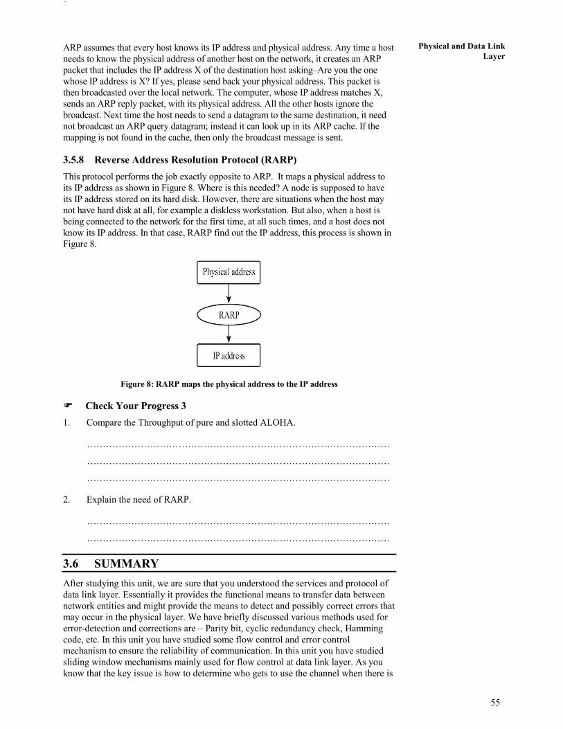
`
55
Physical and Data Link
Layer ARP assumes that every host knows its IP address and physical address. Any time a host
needs to know the physical address of another host on the network, it creates an ARP
packet that includes the IP address X of the destination host asking–Are you the one
whose IP address is X? If yes, please send back your physical address. This packet is
then broadcasted over the local network. The computer, whose IP address matches X,
sends an ARP reply packet, with its physical address. All the other hosts ignore the
broadcast. Next time the host needs to send a datagram to the same destination, it need
not broadcast an ARP query datagram; instead it can look up in its ARP cache. If the
mapping is not found in the cache, then only the broadcast message is sent.
3.5.8 Reverse Address Resolution Protocol (RARP)
This protocol performs the job exactly opposite to ARP. It maps a physical address to
its IP address as shown in Figure 8. Where is this needed? A node is supposed to have
its IP address stored on its hard disk. However, there are situations when the host may
not have hard disk at all, for example a diskless workstation. But also, when a host is
being connected to the network for the first time, at all such times, and a host does not
know its IP address. In that case, RARP find out the IP address, this process is shown in
Figure 8.
Figure 8: RARP maps the physical address to the IP address
���� Check Your Progress 3
1. Compare the Throughput of pure and slotted ALOHA.
……………………………………………………………………………………
……………………………………………………………………………………
……………………………………………………………………………………
2. Explain the need of RARP.
……………………………………………………………………………………
……………………………………………………………………………………
3.6 SUMMARY
After studying this unit, we are sure that you understood the services and protocol of
data link layer. Essentially it provides the functional means to transfer data between
network entities and might provide the means to detect and possibly correct errors that
may occur in the physical layer. We have briefly discussed various methods used for
error-detection and corrections are – Parity bit, cyclic redundancy check, Hamming
code, etc. In this unit you have studied some flow control and error control
mechanism to ensure the reliability of communication. In this unit you have studied
sliding window mechanisms mainly used for flow control at data link layer. As you
know that the key issue is how to determine who gets to use the channel when there is
56
Networks and Devices
competition for it. In this unit, we have studied the protocols used to determine who
goes next on a multi-access channel. In the end of this unit we have studied address
resolution protocols to map between IP addresses and the physical addresses of the
machines.
3.7 REFERENCES/FURTHER READING
1. Computer Networks, A. S. Tanenbaum 4th Edition, Practice Hall of India, New
Delhi. 2003.
2. Introduction to Data Communication & Networking, 3rd Edition, Behrouz
Forouzan, Tata McGraw Hill.
3. Computer Networking, J.F. Kurose & K.W. Ross, A Top Down Approach
Featuring the Internet, Pearson Edition, 2003.
4. Communications Networks, Leon Garcia, and Widjaja, Tata McGraw Hill,
2000.
5. Data and Computer Communications, Willian Stallings, 6th Edition, Pearson
Education, New Delhi.
6. www. wikipedia.org
7. Larry L. Peterson, Computer Networks: A Systems Approach, 3rd Edition (The
Morgan Kaufmann Series in Networking).
3.8 SOLUTIONS/ANSWERS
���� Check Your Progress 1
1. Data link layer is divided into two sublayers LLC and MAC. Logical Link
Control (LLC) concerned with providing a reliable communication part between
two devices. It is also involved with flow control and sequencing. The LLC is
non-architecture-specific and is the same for all IEEE defined LANs. Medium
Access Control (MAC) focuses on methods of sharing a single transmission
medium.
2. Following are services provided by data link layer:
i) Framing: Encapsulation of network layer data packets into frames, and
Frame synchronization
ii) Flow Control: Flow control deals with how to keep the fast sender from
overflowing a slow receiver by buffering and acknowledgement
procedures. This flow control at data link layer is provided in addition to
the one provided on the transport layer.
iii) Error detection and correction codes: Various methods used for error-
detection and corrections are – Parity bit, cyclic redundancy check,
checksum, Hamming code, etc.
iv) Multiple access protocols for channel-access control
v) Physical addressing (MAC addressing)
vi) Quality of Service (QoS) control
3. Parity bit method is very simple error detection method in the digital
communication. A binary digit called “parity” is used to indicate whether the
number of bits with “1” in a given set of bits is even or odd. The parity bit is then
attached to original bits. Assume sender want to send some bit streams like 001
0101 and 101 0011. If we are using even parity bit method, we will add “0” with

`
57
Physical and Data Link
Layer the bit steam having even number of 1’s otherwise add “1”. So our bit steams will
be changed after adding parity bit as 1001 0101and 0101 0011. At the receiver
again the number of 1’s are counted in the original message, if the parity bit is
mismatched we can say an error has occurred in the message. Just like the even
parity we may have odd parity bit method.
4. It is an error control method for data transmission that makes use of error-
detection codes, acknowledgment and/or negative acknowledgment messages, and
timeouts to get reliable data transmission. Generally, when the sender does not
receive the acknowledgment before the timeout occurs, it retransmits the frame
until it is either correctly received or the error persists beyond a predetermined
number of retransmissions. Three types of ARQ protocols are Stop-and-wait
ARQ, Go-Back-N ARQ, and Selective Repeat ARQ, these mechanisms we will
study further in this unit.
���� Check Your Progress 2
1. In Sliding Window data and control frames flow from sender to receiver in a
more continuous manner and several frames can be outstanding at any one time.
Allow multiple outstanding (un-ACKed) frames. Upper bound on un-ACKed
frames, called window. Sender needs to buffer data so that if data is lost, it can
be resent. Receiver needs to buffer data so that if data is received out of order, it
can be held until all packets are received Flow control. The transmitting station
maintains a sending window that maintains the number of frames it is permitted
to send to the receiving station and the receiving station also maintains a
receiving window that performs complementary functions. The two sides use
the window to coordinate the flow of frames between each other. The window
wrap around is used to reuse the same set of numbers for different frames.
There are sliding window techniques:
Go Back N
Selective Repeat
2. This method provides for a more refined approach. In contrast to the Go back
N, the only messages retransmitted are those for which negative
acknowledgement is received. In this the sending process continues to send a
number of frames specified by a window size even after a frame loss. Unlike
Go-Back-N, the receiving process will continue to accept and acknowledge
frames sent after an initial error; this is the general case of the sliding window
protocol with both transmit and receive window sizes greater than 1.
The receiver process keeps track of the sequence number of the earliest frame it
has not received, and sends that number with every acknowledgement (ACK) it
sends. If a frame from the sender does not reach the receiver, the sender
continues to send subsequent frames until it has emptied its window. The
receiver continues to fill its receiving window with the subsequent frames,
replying each time with an ACK containing the sequence number of the earliest
missing frame. Once the sender has sent all the frames in its window, it re-sends
the frame number given by the ACKs, and then continues where it left off.
Now if we compare Selective Repeat behaves in the same way like Go-Back-N ,
it except when the receiver receives a frame which is out of sequence, it sends a
SREJ(Selective Reject) message. Sender retransmits only the rejected packet
and continues with other packets. Here in Selective Repeat method the both the
Sender’s and Receiver’s buffer size are equal to the window size.

58
Networks and Devices
���� Check Your Progress 3
1. Throughput is the percentage of the transmitted frames that arrive successfully
(without collisions) or the percentage of the channel bandwidth that will be
used for transmitting frames without collisions. The throughput ( S) for pure
ALOHA is S = G × e −2G
. The maximum throughput is Smax = 0.184 when G=
(1/2). Where, G is equal to the traffic load. In case of Slotted ALOHA the
throughput is S = G × e−G and the maximum throughput is Smax = 0.368 when G
= 1.
2. RARP maps a physical address to its IP address. Where is this needed? A node
is supposed to have its IP address stored on its hard-disk. However, there are
situations when the host may not have hard disk at all, for example a diskless
workstation. But also when a host is being connected to the network for the first
time, at all such times, a host does not know its IP address. In that case RARP
find out the IP address.

58
Networks and Devices
UNIT 4 INTERNETWORKING DEVICES
Structure Page Nos
4.0 Introduction 58
4.1 Objectives 58
4.2 Internetworking Devices 58 4.2.1 Network interface card
4.2.2 Modem (modulator/demodulator)
4.2.3 Repeaters
4.2.4 Hubs
4.2.5 Bridges
4.2.6 Switch
4.2.7 Gateway
4.3 Summary 69
4.4 References/Further Readings 69
4.5 Solutions/Answers 70
4.0 INTRODUCTION
In this unit, you will learn on various internetwork devices such as NIC adapters,
routers, hubs, switches, modems, gateway and other related devices. A network is
consists of a larger number of the communication devices. The simplest device that is
used in the communication is the NIC adapter which is attached with the every
computer in a network. If you want to build a LAN, you will need to have computers,
hubs, switches, network adapters, UTP/STP cables, routers, internal/external modems,
connectors, cable testers and clipping tool. This unit explains some of mostly used
network devices.
4.1 OBJECTIVES
After going through this unit, you should be able to know:
• Understand various network devices
• Functions of various network devices
• Merits and limitations of various network devices
• Difference between layer 2 and layer 3 switching, and
• Network gateway and its importance.
4.2 INTERNETWORKING DEVICES
Computer network can be established by using various network devices such as such
as cables, Network Interface Cards (NICs), Modems, Repeaters, Hubs, Bridges,
Switches, and Gateways. The following are various internetwork devices that are used
in building LAN/WAN.
4.2.1 Network Interface Card
A network card or network interface controller or network adapter or simply NIC
(network interface card) is a piece of computer hardware designed to allow computers
to communicate over a computer network as shown in Figure 1. It access to a
networking medium and often provides a low-level addressing system through the use
of MAC addresses. It allows users to connect to each other, either by using cables or
wirelessly.

59
Internet Working
Devices
Figure 1: A Network Interface Card (NIC)
Early network interface controllers were commonly implemented on expansion cards
that plugged into a computer bus; the low cost and ubiquity of the Ethernet standard
means that most new computers have a network interface built into the motherboard.
The network controller implements the electronic circuitry required to communicate
using a specific physical layer and data link layer standard such as Ethernet, Wi-Fi, or
Token Ring. This provides a base for a full network protocol stack, allowing
communication among small groups of computers on the same LAN and large-scale
network communications through routable protocols, such as IP.
The NIC may use one or more of four techniques to transfer data:
• Polling is where the CPU examines the status of the peripheral under program
control.
• Programmed I/O is where the microprocessor alerts the designated peripheral
by applying its address to the system's address bus.
• Interrupt-driven I/O is where the peripheral alerts the microprocessor that it is
ready to transfer data.
• Direct memory access is where an intelligent peripheral assumes control of the
system bus to access memory directly. This removes load from the CPU but
requires a separate processor on the card.
4.2.2 Modem (Modulator/Demodulator)
Modem is a device that converts digital and analog signals as shown in the Figure 2.
At the source, modems convert digital signals to a form suitable for transmission over
analog communication facilities (public telephone lines). At the destination, modems
convert the signal back to a digital format.
Figure 2: Modem
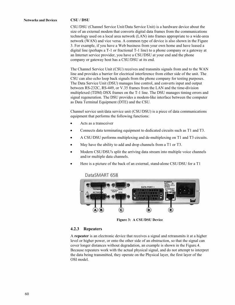
60
Networks and Devices
CSU / DSU
CSU/DSU (Channel Service Unit/Data Service Unit) is a hardware device about the
size of an external modem that converts digital data frames from the communications
technology used on a local area network (LAN) into frames appropriate to a wide-area
network (WAN) and vice versa. A common type of device is also shown in the Figure
3. For example, if you have a Web business from your own home and have leased a
digital line (perhaps a T-1 or fractional T-1 line) to a phone company or a gateway at
an Internet service provider, you have a CSU/DSU at your end and the phone
company or gateway host has a CSU/DSU at its end.
The Channel Service Unit (CSU) receives and transmits signals from and to the WAN
line and provides a barrier for electrical interference from either side of the unit. The
CSU can also echo loop back signals from the phone company for testing purposes.
The Data Service Unit (DSU) manages line control, and converts input and output
between RS-232C, RS-449, or V.35 frames from the LAN and the time-division
multiplexed (TDM) DSX frames on the T-1 line. The DSU manages timing errors and
signal regeneration. The DSU provides a modem-like interface between the computer
as Data Terminal Equipment (DTE) and the CSU.
Channel service unit/data service unit (CSU/DSU) is a piece of data communications
equipment that performs the following functions:
• Acts as a transceiver
• Connects data terminating equipment to dedicated circuits such as T1 and T3.
• A CSU/DSU performs multiplexing and de-multiplexing on T1 and T3 circuits.
• May have the ability to add and drop channels from a T1 or T3.
• Modern CSU/DSU's split the arriving data stream into multiple voice channels
and/or multiple data channels.
• Here is a picture of the back of an external, stand-alone CSU/DSU for a T1
Figure 3: A CSU/DSU Device
4.2.3 Repeaters
A repeater is an electronic device that receives a signal and retransmits it at a higher
level or higher power, or onto the other side of an obstruction, so that the signal can
cover longer distances without degradation, an example is shown in the Figure.4.
Because repeaters work with the actual physical signal, and do not attempt to interpret
the data being transmitted, they operate on the Physical layer, the first layer of the
OSI model.

61
Internet Working
Devices
Figure 4: Repeater
In telecommunication, the term repeater has the following standardized meanings:
An analog device that amplifies an input signal regardless of its nature (analog or
digital).
A digital device that amplifies, reshapes, retimes, or performs a combination of any of
these functions on a digital input signal for retransmission.
4.2.4 Hubs
A hub (concentrator) contains multiple ports as shown in Figure 5, which is used to
connect devices in a star topology. When a packet arrives at one port, it is copied to
all the ports of the hub. But when the packets are copied, the destination address in
the frame does not change to a broadcast address. It does this in a rudimentary way; it
simply copies the data to all of the Nodes connected to the hub (broadcast).
Figure 5: Hub
Advantages and Disadvantages of Hub
Following are some advantages and disadvantages of Hubs:
Advantages:
• Improves performance, especially for bursty traffic and large file transfers
• Enables optimum performance of PCI computers
• Offers ease of use: Fast Ethernet hubs require no hardware or software settings;
just plug them in
• Leverages your knowledge of Ethernet and investment in management tools and
applications
Disadvantages:
• Total bandwidth remains fixed; as network traffic grows, performance suffers

62
Networks and Devices
• The network manager cannot manage network load—for example, by
segmenting the network into multiple collision domains or restricting certain
types of traffic to certain ports
• Does not reduce collisions
• Requires Category 5 UTP cabling for each 100BaseTX connection
4.2.5 Bridges
The main network device found at the data link layer is a bridge. This device works at
a higher layer than the repeater and therefore is a more complex device. It has some
understanding of the data it receives and can make a decision based on the frames it
receives as to whether it needs to let the information pass, or can remove the
information from the network. This means that the amount of traffic on the medium
can be reduced and therefore, the usable bandwidth can be increased.
Bridges are store and forward devices to provide error detection; a common type of
bridge is shown in the Figure 6. They capture an entire frame before deciding whether to
filter or forward the frame, which provides a high level of error detection because a
frame’s CRC checksum can be calculated by the bridge. Bridges are highly susceptible
to broadcast storms. A broadcast storm occurs when several broadcasts are transmitted
at the same time. It can take up huge bandwidth.
Figure 6: Bridge
Advantages and Disadvantages of Bridges
Following are some advantages and disadvantages of Bridges:
Advantages:
• Reliability
• Manageability
• Scalability
Disadvantages:
• A bridge cannot filter out broadcast traffic.
• It introduces 20 to 30 % latency.
• Only 2 networks can be linked with a bridge
���� Check Your Progress 1
1. Explain the meaning of repeaters in analog and digital system
……………………………………………………………………………………
……………………………………………………………………………………

63
Internet Working
Devices 2. What are the advantages and disadvantages of bridges?
……………………………………………………………………………………
……………………………………………………………………………………
……………………………………………………………………………………
4.2.6 Switch
A switch is a data-link layer network device that forwards frames using MAC
addresses in the header of frames. Common types of switches are shown in the Figure
7. It is used to improve network performance by: -
• Segmenting the network and creating separate collision domains.
• Reducing competition for bandwidth.
In a switch frame, forwarding is handled by specialized hardware called "Application
Specific Integrated Circuit" (ASIC). ASIC technology allows a silicon chip to be
programmed to perform specific functions much faster than that of a chip
programmed by software.
Figure 7: Switch
Following are the Steps of Switch Functioning
1. Learning
When switch starts, the MAC address table has no entry. When a node
transmits data on its wire the MAC address of the node is learned by Switch
Port connected to that node. In this way all the MAC addresses are learned by
respective ports and these entries remain in the cache for a specific time. If
during this specific time no new frame arrives from a node MAC address entry
for that node is dropped from cache.
2. Forwarding & Filtering
When a MAC address for a port is learnt, packets addressed to that MAC
address are forwarded only to the port associated with it, using one of the
Switching Methods.
3. Loop Avoidance
Switches and Bridges use Spanning Tree Protocol (STP), specified by IEEE
802.1d, to prevent loops.
Switching Methods
• Store & Forward: in this method the switch receives complete frame. CRC
(Cyclic Redundancy Check), source address and destination address are
checked.

64
Networks and Devices
• Cut Through: In this method forwarding starts as soon as destination address
of the frame is received in header. Also known as WIRE SPEED.
• Fragment Free (Modified Cut Through): In this method forwarding starts as
soon as first 64 bytes of the frame are received as fragmentation occurs usually
in first 64 bytes.
Advantages and Disadvantages of Switch
Following are some advantages and disadvantages of switches:
Advantages:
• Reduces the number of Broadcast domains
• Supports VLAN's (virtual local area network (VLAN) is a logical grouping of
hosts on one or more LANs that allows communication to occur between hosts
as if they were on the same physical LAN.) that can help in Logical
segmentation of ports [physical ports]. Splitting up the broadcast domain.
• Intelligent device [compared to Hub's] which can make use of CAM table for
Port to MAC mapping
• Compared to Bridges, Switches are more H/w oriented therefore operations are
less CPU intense [Basic operations]
• The cost to number of ports ratio is best i.e. for a cheaper cost you get switches
with more number of ports available than Routers.
Disadvantages:
• Not as good as a router in limiting Broadcasts
• Communication between VLAN's need inter VLAN routing [Router], but these
days there are a number of Multilayer switches available in the market.
• Handling Multicast packets needs quite a bit of configuration and proper
designing.
Layer 2 Switch
Layer 2 switching uses the media access control address (MAC address) from the
host's network interface cards (NICs) to decide where to forward frames. Layer 2
switching is hardware based, which means switches use application-specific
integrated circuit (ASICs) to build and maintain filter tables (also known as MAC
address tables). One way to think of a layer 2 switch is as a multi-port bridge.
• Layer 2 switching provides the following:Hardware-based bridging (MAC)
• Wire speed
• High speed
• Low latency
• Low cost
Layer 2 switching is highly efficient because there is no modification to the data
packet, only to the frame encapsulation of the packet, and only when the data packet
is passing through dissimilar media (such as from Ethernet to FDDI). Layer 2
switching is used for workgroup connectivity and network segmentation (breaking up
collision domains). This allows a flatter network design with more network segments
than traditional 10BaseT shared networks. Layer 2 switching has helped develop new
components in the network infrastructure.

65
Internet Working
Devices • Server farms — Servers are no longer distributed to physical locations because
virtual LANs can be created to create broadcast domains in a switched
internetwork. This means that all servers can be placed in a central location, yet
a certain server can still be part of a workgroup in a remote branch.
• Intranets — Allows organization-wide client/server communications based on a
Web technology.
These new technologies allow more data to flow off from local subnets and onto a
routed network, where a router's performance can become the bottleneck.
Limitations
Layer 2 switches have the same limitations as bridge networks.
Bridged networks break up collision domains, but the network remains one large
broadcast domain. Similarly, layer 2 switches (bridges) cannot break up broadcast
domains, which can cause performance issues and limits the size of your network.
Broadcast and multicasts, along with the slow convergence of spanning tree, can
cause major problems as the network grows. Because of these problems, layer 2
switches cannot completely replace routers in the internetwork.
Layer 3 Switch
A Layer 3 switch is a high-performance device for network routing. Layer 3 switches
actually differ very little from routers. A Layer 3 switch can support the same routing
protocols as network routers do. Both inspect incoming packets and make dynamic
routing decisions based on the source and destination addresses inside. Both types of
boxes share a similar appearance.
Layer 3 switches were conceived as a technology to improve on the performance of
routers used in large local area networks (LANs) like corporate intranets. The key
difference between Layer 3 switches and routers lies in the hardware technology used
to build the unit. The hardware inside a Layer 3 switch merges that of traditional
switches and routers, replacing some of a router's software logic with hardware to
offer better performance in some situations.
Layer 3 switches often cost less than traditional routers. Designed for use within local
networks, a Layer 3 switch will typically not possess the WAN ports and wide area
network features a traditional router will always have.
Layer 3 switches can be placed anywhere in the network because they handle high-
performance LAN traffic and can cost-effectively replace routers. Layer 3 switching
is all hardware-based packet forwarding, and all packet forwarding is handled by
hardware ASICs.
Functions of Layer 3 switch
1. Determine paths based on logical addressing
2. Run layer 3 checksums (on header only)
3. Use Time to Live (TTL)
4. Process and respond to any option information
5. Update Simple Network Management Protocol (SNMP) managers with
Management Information Base (MIB) information
6. Provide Security
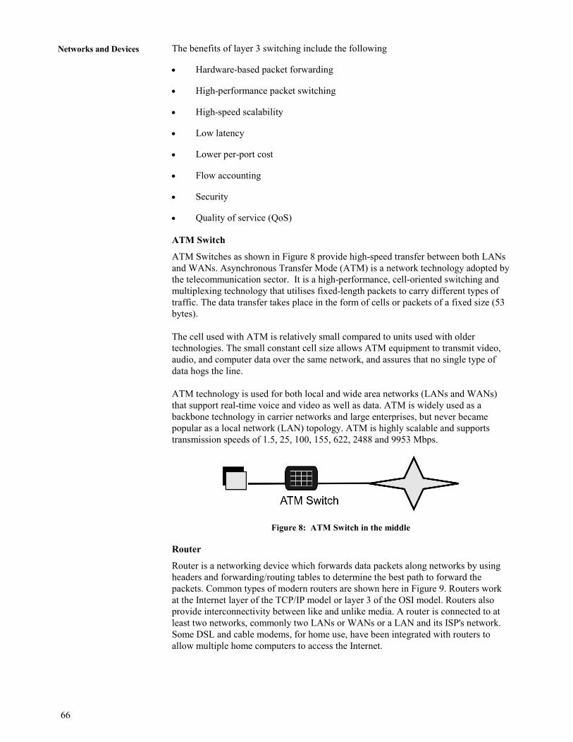
66
Networks and Devices
The benefits of layer 3 switching include the following
• Hardware-based packet forwarding
• High-performance packet switching
• High-speed scalability
• Low latency
• Lower per-port cost
• Flow accounting
• Security
• Quality of service (QoS)
ATM Switch
ATM Switches as shown in Figure 8 provide high-speed transfer between both LANs
and WANs. Asynchronous Transfer Mode (ATM) is a network technology adopted by
the telecommunication sector. It is a high-performance, cell-oriented switching and
multiplexing technology that utilises fixed-length packets to carry different types of
traffic. The data transfer takes place in the form of cells or packets of a fixed size (53
bytes).
The cell used with ATM is relatively small compared to units used with older
technologies. The small constant cell size allows ATM equipment to transmit video,
audio, and computer data over the same network, and assures that no single type of
data hogs the line.
ATM technology is used for both local and wide area networks (LANs and WANs)
that support real-time voice and video as well as data. ATM is widely used as a
backbone technology in carrier networks and large enterprises, but never became
popular as a local network (LAN) topology. ATM is highly scalable and supports
transmission speeds of 1.5, 25, 100, 155, 622, 2488 and 9953 Mbps.
Figure 8: ATM Switch in the middle
Router
Router is a networking device which forwards data packets along networks by using
headers and forwarding/routing tables to determine the best path to forward the
packets. Common types of modern routers are shown here in Figure 9. Routers work
at the Internet layer of the TCP/IP model or layer 3 of the OSI model. Routers also
provide interconnectivity between like and unlike media. A router is connected to at
least two networks, commonly two LANs or WANs or a LAN and its ISP's network.
Some DSL and cable modems, for home use, have been integrated with routers to
allow multiple home computers to access the Internet.
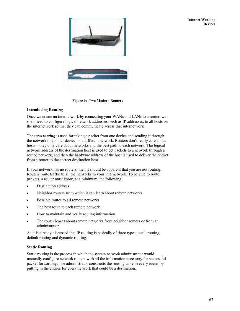
67
Internet Working
Devices
Figure 9: Two Modern Routers
Introducing Routing
Once we create an internetwork by connecting your WANs and LANs to a router, we
shall need to configure logical network addresses, such as IP addresses, to all hosts on
the internetwork so that they can communicate across that internetwork.
The term routing is used for taking a packet from one device and sending it through
the network to another device on a different network. Routers don’t really care about
hosts—they only care about networks and the best path to each network. The logical
network address of the destination host is used to get packets to a network through a
routed network, and then the hardware address of the host is used to deliver the packet
from a router to the correct destination host.
If your network has no routers, then it should be apparent that you are not routing.
Routers route traffic to all the networks in your internetwork. To be able to route
packets, a router must know, at a minimum, the following:
• Destination address
• Neighbor routers from which it can learn about remote networks
• Possible routes to all remote networks
• The best route to each remote network
• How to maintain and verify routing information
• The router learns about remote networks from neighbor routers or from an
administrator
As it is already discussed that IP routing is basically of three types: static routing,
default routing and dynamic routing.
Static Routing
Static routing is the process in which the system network administrator would
manually configure network routers with all the information necessary for successful
packet forwarding. The administrator constructs the routing table in every router by
putting in the entries for every network that could be a destination.

68
Networks and Devices
Default Route
A default route is often called the 'route of last resort'. It is the last route tried by a
router when all other routes fail because it has the fewest number of network bits
matching and is therefore less specific. We use default routing to send packets with a
remote destination network not in the routing table to the next-hop router. You should
only use default routing on stub networks—those with only one exit path out of the
network. To configure a default route, you use wildcards in the network address and
mask locations of a static route. In fact, you can just think of a default route as a static
route that uses wildcards instead of network and mask information.
The syntax for Default routing is : ip route 0.0.0.0 0.0.0.0 <next hop or exit interface
Dynamic Routing
Dynamic routing is when protocols (Routing Protocols) are used to find networks and
update routing tables on routers. This is easier than using static or default routing, but
it’ll cost in terms of router CPU processes and bandwidth on the network links. The
chief advantages of dynamic routing over static routing are scalability and
adaptability. A dynamically routed network can grow more quickly and larger, and is
able to adapt to changes in the network topology brought about by this growth or by
the failure of one or more network components. Chief among the disadvantages is an
increase in complexity.
4.2.7 Gateway
In a communications network, gateway is a network node equipped for interfacing
with another network that uses different protocols.
A gateway may contain devices such as protocol translators, impedance matching
devices, rate converters, fault isolators, or signal translators as necessary to provide
system interoperability. It also requires the establishment of mutually acceptable
administrative procedures between both networks. A protocol translation/mapping
gateway interconnects networks with different network protocol technologies by
performing the required protocol conversions.
A gateway is a network point that acts as an entrance to another network. On the
Internet, gateway is a node or stopping point node or a host (end-point) node. Both the
computers of Internet users and the computers that serve pages to users are host
nodes, while the nodes that connect the networks in between are gateways. For
example, the computers that control traffic between company networks or the
computers used by internet service providers (ISPs) to connect users to the internet
are gateway nodes.
In the network for an enterprise, a computer server acting as a gateway node is often
simultaneously acting as a proxy server and a firewall server. A gateway is often
associated with both a router, which knows where to direct a given packet of data that
arrives at the gateway, and a switch, which furnishes the actual path in and out of the
gateway for a given packet.
On an IP network, clients should automatically send IP packets with a destination
outside a given subnet mask to a network gateway. A subnet mask defines the IP
range of a private network. For example, if a private network has a base IP address of
192.168.0.0 and has a subnet mask of 255.255.255.0, then any data going to an IP
address outside of 192.168.0.X will be sent to that network's gateway. While
forwarding an IP packet to another network, the gateway might or might not perform
Network Address Translation.

69
Internet Working
Devices Most computer operating systems use the terms described above. Microsoft Windows,
however, describes this standard networking feature as Internet Connection Sharing,
which acts as a gateway, offering a connection between the Internet and an internal
network. Such a system might also act as a DHCP server. Dynamic Host
Configuration Protocol (DHCP) is a protocol used by networked devices (clients) to
obtain various parameters necessary for the clients to operate in an Internet Protocol
(IP) network. By using this protocol, system administration workload greatly
decreases, and devices can be added to the network with minimal or no manual
configurations.
���� Check Your Progress 1
1. Explain the advantages of using switch. Also discuss its disadvantages.
……………………………………………………………………………………
……………………………………………………………………………………
……………………………………………………………………………………
……………………………………………………………………………………
2. What is network gateway? Explain
……………………………………………………………………………………
……………………………………………………………………………………
……………………………………………………………………………………
……………………………………………………………………………………
4.3 SUMMARY
In this unit, various internetwork components used in a computer network are explained.
Some of the components such as NIC, Modem, Repeater, Hub, Switch and their
functions along with merits and limitations are clearly discussed. After completing this
unit you can understand the importance of various internetworking devices particularly
at the network layer. You have also studied the different switching and routing methods
in this unit. The block of this course has presented the details of transport layer and
application layer.
4.4 REFERENCES/FURTHER READINGS
1) Computer Networks, A. S. Tanenbaum 4th Edition, Practice Hall of India, New
Delhi. 2003.
2) Computer Networking, J.F. Kurose & K.W. Ross, A Top Down Approach
Featuring the Internet, Pearson Edition, 2003.
3) Introduction to Data Communication & Networking, Behrouz Forouzan, Tata
McGraw Hill, 1999.
4) Communications Networks, Leon Garcia, and Widjaja, Tata McGraw Hill, 2000.
5) Data and Computer Communications, Willian Stallings, 6th Edition, Pearson
Education, New Delhi.
6) www.wikipedia.org

70
Networks and Devices
4.5 SOLUTIONS/ANSWERS
���� Check Your Progress 1
1. In telecommunication, the term repeater has the following standardized
meanings:
• An analog device that amplifies an input signal regardless of its nature
(analog or digital).
• A digital device that amplifies, reshapes, retimes, or performs a
combination of any of these functions on a digital input signal for
retransmission.
2. Following are some advantages and disadvantages of Bridges:
Advantages:
• Reliability
• Manageability
• Scalability
Disadvantages:
• A bridge cannot filter out broadcast traffic.
• It introduces 20 to 30 % latency.
• Only 2 networks can be linked with a bridge
���� Check Your Progress 2
1. Following are some advantages and disadvantages of switches:
Advantages:
• Reduces the number of Broadcast domains
• Supports VLAN's (virtual local area network (VLAN) is a logical
grouping of hosts on one or more LANs that allows communication to
occur between hosts as if they were on the same physical LAN.) that can
help in Logical segmentation of ports [physical ports]. Splitting up the
broadcast domain.
• Intelligent device [compared to Hub's] which can make use of CAM table
for Port to MAC mapping
• Compared to Bridges, Switches are more H/w oriented therefore
operations are less CPU intense [Basic operations]
• The cost to number of ports ratio is best i.e. for a cheaper cost you get
switches with more number of ports available than Routers.
Disadvantages:
• Not as good as a router in limiting Broadcasts
• Communication between VLAN's need inter VLAN routing [Router], but
these days there are a number of Multilayer switches available in the
market.
• Handling Multicast packets needs quite a bit of configuration & proper
designing.
2. In a communications network, gateway is a network node equipped for
interfacing with another network that uses different protocols.

71
Internet Working
Devices A gateway may contain devices such as protocol translators, impedance
matching devices, rate converters, fault isolators, or signal translators as
necessary to provide system interoperability. It also requires the establishment
of mutually acceptable administrative procedures between both networks. A
protocol translation/mapping gateway interconnects networks with different
network protocol technologies by performing the required protocol conversions.


![revista 041 [6]](https://img.pdfslide.us/doc/110x75/568c0d841a28ab955a8d006f/revista-041-6.jpg)