Embed Size (px)
Citation preview

BCS-041
Fundamental
of Computer Networks
Block
4 NETWORK TRANSPORT AND APPLICATION
LAYER
UNIT 1
Building A Simple Network 5
UNIT 2
Introduction to Network Architectures 26
UNIT 3
Introduction to Wireless and Mobile Networks 48
UNIT 4
Network Security 70
Indira Gandhi National Open University
School of Computer and
Information Sciences
PROGRAMME DESIGN COMMITTEE
Prof. Manohar Lal,
SOCIS, IGNOU, New Delhi
Prof. H.M Gupta
Dept. of Elect. Engg., IIT, Delhi
Prof. M.N Doja, Dept. of CE
Jamia Millia, New Delhi
Prof. C. Pandurangan
Dept. of CSE, IIT, Chennai
Prof. I. Ramesh Babu
Dept. of CSE
Acharya Nagarjuna University,
Nagarjuna Nagar (AP)
Prof. N.S. Gill
Dept. of CS, MDU, Rohtak
Prof. Arvind Kalia, Dept. of CS
HP University, Shimla
Prof. Anju Sehgal Gupta
SOCIS, IGNOU, New Delhi
Prof. Sujatha Verma
SOS, IGNOU, New Delhi
Prof. V. Sundarapandian
IITMK, Trivendrum
Prof. Dharamendra Kumar
Dept. of CS, GJU, Hissar
Prof. Vikram Singh
Dept. of CS, CDLU, Sirsa
Sh. Shashi Bhushan, Associate. Prof.
SOCIS, IGNOU, New Delhi
Sh. Akshay Kumar, Associate Prof.
SOCIS, IGNOU, New Delhi
Dr. P.K. Mishra, Associate Prof.
Dept. of CS, BHU, Varanasi
Sh. P.V. Suresh, Asst. Prof.
SOCIS, IGNOU, New Delhi
Sh. V.V. Subrahmanyam, Asst. Prof.
SOCIS, IGNOU, New Delhi
Sh. M.P. Mishra, Asst. Prof.
SOCIS, IGNOU, New Delhi
Dr. Naveen Kumar, Asst. Prof.
SOCIS, IGNOU, New Delhi
Dr. Subodh Kesharwani, Asst. Prof.
SOMS, IGNOU, New Delhi
COURSE CURRICULUMDESIGN COMMITTEE
Prof. R. S.Gupta, Professor (Retd.),
University of Roorkee, Roorkee,
Prof. Sujatha Varma, Profesor,
SOS, IGNOU, New Delhi
Sh. Milind Mahajani
Sr. IT Consultant, New Delhi
Dr. D.K.Lobiyal, Associate Prof.,
SC&SS, JNU, New Delhi
Sh. Akshay Kumar, Associate Prof.
SOCIS, IGNOU, New Delhi
Dr. Parvin Chandra, Associate Prof.,
IIC, Delhi University, New Delhi
Sh. P. V. Suresh, Asst. Prof.
SOCIS, IGNOU, New Delhi
Sh. M.P. Mishra, Asst. Prof.
SOCIS, IGNOU, New Delhi
Dr. Naveen kumar, Asst. Prof.
SOCIS, IGNOU, New Delhi
COURSSOCIS FACULTY
Sh. Shashi Bhushan, Director Sh. Akshay Kumar, Associate Prof. Dr. P.V. Suresh, Associate Prof.
Sh. V.V. Subrahmanyam, Associate Prof. Dr. Naveen Kumar, Reader Sh. M.P. Mishra, Asst. Prof.
COURSE BLOCK PREPARATION TEAM
Dr. Sudhans Sharma, Asst. Prof.,
(Unit-1 Writer), SOCIS, IGNOU, New Delhi
Dr. Naveen Kumar, Reader
(Unit-2 Writer),
SOCIS, IGNOU, New Delhi
Ms. Radhika Saini, Software
Engineer,(Unit-3 and 4 Writer), Hutchison Essar Mobile Services,
New Delhi
Dr. Naveen Kumar, Reader
(Unit-1,3,4 Transformation),
SOCIS, IGNOU, New Delhi
Dr. D.K.Lobiyal (Language Editor)
Assoc. Prof., SC&SS, JNU, New Delhi
Dr. Parmod Kumar, Asst. Prof.,
(Language Editor),
SOH, IGNOU, New Delhi
Course Coordinator : Dr. Naveen Kumar, Reader, SOCIS, IGNOU, New Delhi
PRINT PRODUCTION: Sh. Tilak Raj, S.O.(P), CRC Prepared by Smt. Dolly Singh
ISBN:
© Indira Gandhi National Open University, 2013
All rights reserved. No part of this work may be reproduced in any form, by mimeograph or any form, by mimeograph or any other means, without permission in writing form the Indira Gandhi National Open University.
Further information on the Indira Gandhi National Open University courses may be obtained from the University’s office
at Maidan Garhi, New Delhi-110068.
Printed and published on behalf of the Indira Gandhi National Open University by the Director, SOCIS.
COURSE INTRODUCTION
Computer networking is the practice of connecting two or more computing devices for
the purpose of communication and sharing data. These networks are designed with a
set of computer hardware and computer software. The various communication
functions and services of networking are grouped into seven layers according to OSI reference model. These layers are called Physical, Data Link, Network, Transport,
Session, Presentation and Application Layer. This course introduces the basics of data
communication and networking. Students will develop an understanding of the general principles of data communication and networking as used in networks. It also
includes an activity of setting up a small local area network. The objective of this
course is to enable students in developing an understanding of the structure of network, its elements and how these elements operate and communicate with each
other. Along with this course material of BCS-041, you must read the book and study
material suggested you in the last of each unit. This course on fundamentals of
computer networks is divided in the following four blocks:
The Block 1: Concepts of Communication and Networking gives an introduction
of data communication and networking. It covers basic details of techniques, methods
and schemes used at the physical and data link layer of OSI model.
Block 2: Networks and Devices is an introduction to the various hardware devices
and wires used for designing different networks. Most of these hardware devices are used at physical, data link and network layer of OSI model.
Block 3: Network, Transport & Application Layer covers the details of various
protocols used in the top three layers Network, Transport and Application Layer of the
OSI model.
Block 4: Network Design & Security will give you the fundamental details for
setting up a small local area network including wired and wireless setup. This block will also cover the foundational details of network security protocols and wireless
networking.
BLOCK INTRODUCTION
This block named Network Design & Security gives an introduction of network
designing. It begins with basic details of different network architectures. Further this
block gives Introduction to Wireless and Mobile Networks. This block also discusses
the importance and requirements of security services and protocols. This block is divided into the following four units:
Unit 1: Building a Simple Network. In this unit you will learn about the ways and means, required to build a simple network. In this unit you will learn about sharing of
files though networking, configuring a network device, configuring a network in
wired/wireless mode. It also discusses one example of designing the developing small networks.
Unit 2: Introduction to Network Architectures. This unit is an introduction to
network architecture, in which we will discuss about different network architectures
like X.25, Frame Relay, ATM. Further, it covers IPv4 and IPv6 protocol details. We
will also discuss the mechanisms for implementing/deploying IPv6 in this unit.
Unit 3: Introduction to Wireless and Mobile Networks, which gives an introduction
to wireless communication and cellular mobile systems.
Unit 4: Network Security. This unit discusses about various Security services and
requirements. It also covers different Public and Private Key Cryptography algorithms
like RSA, MD5 and DES which are used to provide security services in the networks.
5
Building A Simple
Network
UNIT 1 BUILDING A SIMPLE NETWORK
Structure Page No.
1.0 Introduction 5
1.1 Objectives 5
1.2 Structure Cabling 5 1.2.1 Assembling patch cable
1.3 Integrating Home Computers 14 1.3.1 How to connect two computers by using cross-over cable?
1.3.2 How to share data between two computers?
1.4 Creating a small Network 16 1.4.1 How to connect computers using hub / switch ?
1.4.2 How to create cluster of switches/hubs ?
1.4.3 How to configure a wireless network?
1.5 Case: Designing & Development of Small Networks 19
1.6 Summary 24
1.7 Solutions /Answers 24
1.8 References 25
1.0 INTRODUCTION
Computer Networks forms the basis of the present day’s communication. It comprises
of the technology that makes the world to work. While structuring the network, one
need to have sound knowledge of both software and hardware components associated
with computer networking. Hardware settings involves structuring of cables, electrical
connectivity, fixing access points etc, whereas the software setting helps the network
administrator to make the hardware component work properly.
In this unit you will learn about the ways and means, required to build a simple
network i.e. a network that can be used for your day to day working viz. sharing of
files, configuring a network device, configuring a network in wired/wireless mode and
so on. We will sum up this unit with a simple case discussed in section 1.5 of this unit,
the case relates to “Designing & Development of small networks”, through this case
you will be able to understand the practical utility and benefit of this unit.
In a wired computer network the structured cabling forms the backbone of the
network. This unit starts with the discussion over structured cabling, which is later
extended to the depth of computer networks, suitable for your level.
1.1 OBJECTIVES
After going through this unit you will be able to:
• Identify the prominent problems associated with networking;
• Propose basic network solution for the identified network problems;
• Perform basic hardware structuring, required for network layout and ;
• Perform software settings, required to make a workable network.
1.2 STRUCTURE CABLING
The term structured cabling is related the cabling and connectivity products used to
integrate voice, data, video etc. over LAN(Local Area Network).The cables and
connectivity products are desired to be used in a systematic way, such that the
organized cabling system can be easily understood by installers, network
administrators, and any other technician that deals with cabling. To maintain the
6
Network Transport
and Application
Layer
world wide code of conduct for structured cabling, standards are laid by industry viz.
The EIA/TIA (Electronic Industries Association / Telecommunication Industry
Association) and ISO/IEC (International Standards Organization/ International
Electrotechnical Commission) have created industry standards for cabling. These
standards results the standardized cabling architectures, which allows a single
delivery method to be designed for support and services in the workspace.
However, to ensure the efficient and effective structured cabling design, three rules
are advised to be followed :
1. Look for a complete connectivity: Connectivity includes all the systems
that are designed to connect, route, manage, and identify cables in structured
cabling systems.
2. Plan for future growth : The number of cables installed should also meet
future requirements. Category 5e, Category 6, and fiber-optic solutions should
be considered to ensure that the future needs will be met.
3. Freedom of choice in vendors. Even though a closed and proprietary system
may be less expensive initially, this could end up being much more costly over
the long term. A non-standard system from a single vendor may make it more
difficult to make moves, adds, or changes at a later time.
Before applying the rules to ensure reasonably good cabling mechanism, we need to
do some home work, related to the length of cables required (Number of Bundles),
secondly type of cable required viz. shielded or unshielded (UTP-Unshielded Twisted
Pair cable). Further, we need to choose the cable as per the distance i.e. for ~ 100m
length of network coverage cat5e option of cable is fine but for ~150m length of
network coverage cat6 is to be opted, after that length we need to use repeaters. Now,
we need to understand where to use sheathed cable and where to use unsheathed
cable. The Shielded cable is thick and more protected to physical damages, thus it is
generally used in the situations where physical endurance is more required viz.
dragging the cable through some pipe or so. Further, you need to understand the
components involved in entire cabling process, viz. The connectors, patch cords, cable
and its types. So, we start with the understanding of related components viz
connectors, patch cords etc. in a sequential manner.
The Structured cabling of an Ethernet systems, leads to increase the flexibility and
cost-effectiveness of transmitting voice, data, and multimedia over integrated
networks. Ethernet patch cords are fast, and they are becoming a familiar part of our
everyday experience. These ubiquitous cables have played a central role in the
development of generic and structured cabling systems, and today are used for
connecting virtually all networking components, without regard to a particular
application or industry. In all of these ways, patch cords are the Ether of the Ethernet.
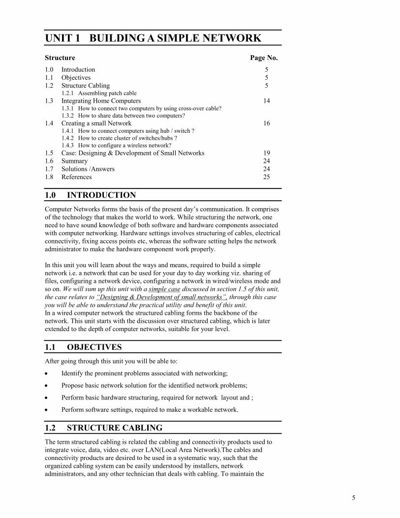
These Ethernet patch cords are clubbed with RJ45 (RJ-Registered Jack) connectors,
these are the connectors which holds 8P8C (“8 position, 8 conductor”) configuration.
Refer to figure-1 to map RJ45 with the 8P8C configuration
Figure 1: 8P8C connector plug commonly referred as RJ 45

7
Building A Simple
Network
In Ethernet networks, these RJ-45 plugs and jacks form a modular, gendered
connector system that helps in making dynamic alterations in network components in
a fast and easy way. The male plugs and female jacks are held together by a spring-
loaded tab—called a hook—that keeps them securely in place while in use, but allows
them to be easily unplugged when changes are made to a network system or work
area.
The patch cords used in most Ethernet systems are constructed using UTP(Unshielded
Twisted-Pair) cable. UTP cable consists of eight insulated copper-core conductors
grouped into four pairs, with each pair twisted together along the cable’s length. The
conductor pairs and individual conductors in UTP cables are represented by a color
code that assigns a primary color—blue, orange, green, or brown—to each of the 4
twisted pairs. The insulation of a conductor within a pair is either a solid primary
color, or white striped with that primary color. In this way, all conductors are
identified as members of a specific twisted pair, and as individual members within
that pair. The conductor pairs are numbered 1 to 4 as shown in Figure -2 below, where
Pair 1 corresponding to the blue pair, Pair 2 to the orange pair, Pair 3 to the green
pair, and Pair 4 to the brown pair. The individual conductors in UTP cables can be
solid copper-core wires with a well-defined thickness, or bundles of fine copper wire
strands. Even though the solid-conductor cables are less expensive and easier to
terminate, patch cords are almost always made from stranded cables. This is because
the stranding of the conductors increases the cable’s flexibility and durability.
Figure 2: UTP Cable Cross Section Figure 3: CAT-5E UTP Cable
You might be thinking , what’s the use of twisting the cable, why not we use the
straight strands of the cable. To answer your question you need to understand a lot of
Physics associated with it, but in short, The twisted conductor pairs in UTP cables
form a balanced circuit. This is because the voltages of each member in a given pair
has the same amplitude (the same voltage magnitude), but their voltages are opposite
in phase (one voltage is positive, and the other is negative). The uniform twisting of
each of these balanced pairs reduces electromagnetic interference (EMI) and radio
frequency interference (RFI) originating from other conducting pairs inside the cable,
or from equipment in the cable’s environment. The conductor pairs inside a twisted-
pair cable influence one another through a type of EMI called crosstalk. Crosstalk
occurs when the electromagnetic field generated by one pair is large enough (the
pair’s signal is strong enough) to cross over to the location of a neighboring pair.
You are required to go through the following key points given in the form of notes,
below. These key points will let you to understand various aspects related to the
various questions which might be boggling in your mind like “How the number of
turns in the UTP, relates to its performance ? ” Or “ What is the relevance of shielding
the Cable?” Or “ What are the various IEEE and EIA/TIA cabling Standards, how
they differ ?” Or “ When to use which type of cable?” Or “ What is the difference
between CAT 5/CAT 5e/Cat6 cables, when to use which cable?”. in the discussion
below we try to answer all these questions.

8
Network Transport
and Application
Layer
NOTE:
1. How the number of turns in the UTP, relates to its performance ?
The greater the number of conductor twists, the better a cable’s immunity to
EMI and RFI. This immunity gets even better when the number of twists per
unit length (the twist rate) is varied among the four pairs. For example,
manufacturers of higher-grade cables employ variations in the twist rates of
individual conductor pairs, using a different twist rate for each of the four pairs
in order to minimize the crosstalk between them.
2. What is the relevance of shielding the Cable?
Wrapping each conductor pair with a foil shielding further reduces the crosstalk
among pairs, and wrapping all four of the twisted-pairs in a foil or braided
metallic shield reduces a cables susceptibility to EMI and RFI in noisy cable
environments. Thus, STP (Shielded Twisted Pair) cables employ both types of
shielding, giving them the highest immunity to all interference types. FTP (Foil
Twisted Pair) and ScTP (Screened Twisted Pair) cables employ only the outer
foil or braided-conductor shielding, giving them enhanced immunity against
external EMI and RFI, but no more protection against crosstalk than an equally-
constructed UTP cable.
3. What are the various IEEE cabling Standards, how they differ?
10Base-T and 100Base-T are the IEEE (Institute of Electrical and Electronics
Engineers) standards defining the electrical and physical characteristics of
twisted-pair cabling for use in 10 Mbps (Megabits per second) and 100Mbps
Ethernet connections. The “T” stands for Twisted pair, and these two Ethernet
connections use wire pairs 2 and 3 to transmit and receive information,
corresponding to the orange and green twisted pair conductors shown in Figure
2. Nowadays we use the Gigabit Ethernet (or 1000Base-T), where all four
conductor pairs shown in Figure 2 above, are used to transmit and receive
information simultaneously.
4. What are the various EIA/TIA cabling Standards, how they differ?
568A and 568B are EIA/TIA(Electronics Industry
Association/Telecommunications Industry Association) wiring standards
specifying two different RJ-45 pin assignments for the orange and green
conductor pairs in Category-type twisted-pair cables. The wiring for two
different conductor/pin configurations is shown in Figure 4, and the same are
tabulated in Table-1below. You should observe that, the Ethernet patch cords
with connectors wired using the same standard on both ends, are referred as
“Straight Through Cable” and those with different standards are referred as
“Crossover cable”. In Brief, to create a straight-through cable, you'll have to
use either T-568A or T-568B on both ends of the cable. To create a cross-
over cable, you'll wire T-568A on one end and T-568B on the other end of the
cable. The general structuring of Straight Through and Cross Over Cable is
shown in Figure 5 below.
Figure 4: 568A and 568B are EIA/TIA wiring standards -specifying different RJ-45
pin assignments

9
Building A Simple
Network
Table 1: Wiring Diagram for EIA/TIA Standards 568a and 568b
Figure 5: Straight-Through Cable and Cross Over Cable
5. When to use which type of cable?
The straight-through cables are used when connecting Data Terminating
Equipment (DTE) to Data Communications Equipment (DCE), such as
computers and routers to modems (gateways) or hubs (Ethernet Switches). The
cross-over cables are used when connecting DTE to DTE, or DCE to DCE
equipment; such as computer to computer, computer to router; or gateway to
hub connections. The DTE equipment terminates the signal, while DCE
equipment do not. To simplify, we tabulated the generalized situations, where
you might be expected to use the respective cables. i.e. Crossover cable or
Straight Through Cable:
Computer to Computer – Crossover
Switch to Switch – Crossover
Computer to Modem – Straight Through
Computer to Switch – Straight Through
Switch To Router – Both (if problems, go with Crossover)
6. What is the difference between CAT 5/ 5e / 6 cables, when to use which
cable?
Making the choice between types of Ethernet cables available for networking
and connecting their computers to the Internet viz. Cat 5, Cat 5e, and Cat 6
cables can be confusing. To distinguish between the various types of cables,
you have to understand the nomenclature, the term Cat being short for
“Category”, whereas the numbers and letters to follow are all used to indicate
performance. These performance designations make it easier to choose the right
type for various purposes such as networking computers together or using
peripherals including hubs and routers. All three types of cables, Cat 5, Cat 5e,
Pair # Wire Pin #
1-White/Blue White/Blue 5
Blue/White 4
2-White/Green White/Green 1
Green/White 2
3-White/Orange White/Orange 3
Orange/White 6
4-White/Brown White/Brown 7
Brown/White 8
568-A Wiring Diagram
Pair # Wire Pin #
1-White/Blue White/Blue 5
Blue/White 4
2-Wht./Orange White/Orange 1
Orange White 2
3-White/Green White/Green 3
Green/White 6
4-White/Brown White/Brown 7
Brown/White 8
568-B Wiring Diagram
10
Network Transport
and Application
Layer
and Cat 6, are comprised of four pairs of UTP (unshielded twisted pair), but the
amount of transmissions the cable will be able to support is up to its category
rating.
The Original Cat 5 Cable : An old standard in the industry, Cat 5 cable is able
to perform up to 100MHz and is still widely used for a variety of applications,
although most new installations will use Cat 5e or higher. Able to support
10/100 Ethernet and fast Ethernet, Cat 5 cable is upwardly compatible with the
Cat 5e version.
The Improved Cat 5e Cable : With improved durability over Cat 5, the
protective outer covering of Cat 5e cable is thicker and therefore more suitable
and reliable for more situations than its earlier counterpart. There are several
other differences between this version and its predecessor including its
backwards compatibility, as it will work along with either 10BaseT or 100Base
T networking hubs and cards. There is also less cross talk or electronic
interference with Cat 5e as opposed to Cat 5 cable thanks to improved signal
capabilities. In terms of bandwidth, Cat 5e supports gigabit Ethernet
connections of up to 350MHz, more than trebling the 100MHz of a Cat 5 cable.
Remember that Cat 5e cable is not rated for outdoor use, although many people
do without incident. If you must use this cable outside, add a conduit such as
one made from PVC to keep moisture away. The safe operating temperature for
Cat 5e cable is anywhere from 10 degrees Celsius to 60 degrees Celsius.
Also, with this particular category cable, 100 meters is the maximum length you
will be able to use the cable without the benefit of either a network bridge, hub,
or amplification to strengthen the signal.
The Cat 6 Cable :Certified and designed specifically for gigabit use, Cat 6 cable
reduces cross talk even more than its predecessors by improving upon the
original Cat 5 version with wires featuring extra twists. The use of Cat 6 cable
does not guarantee that the network will be a full gigabit network, for this to be
achieved each and every one of the components must be gigabit certified.
Unless your network meets this criteria, opt for Cat 5e which will provide high
quality speeds while saving money in the process.
For quick reference, here are the ratings of the various category cables: Cat 5 up
to 100MHz ; Cat 5e up to 350MHz; Cat 6 up to 550MHz
1.2.1 Assembling Patch Cable
By learning the theoretical aspects of structured cabling, you might be exhausted. So,
let's apply our learnt skills in a practical manner, just follow the instructions given
below and you will be able to produce your own patch cable assembly.
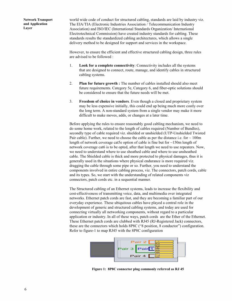
Steps to assemble Patch Cable:
1. Cut the cable to the length that you will need.
11
Building A Simple
Network
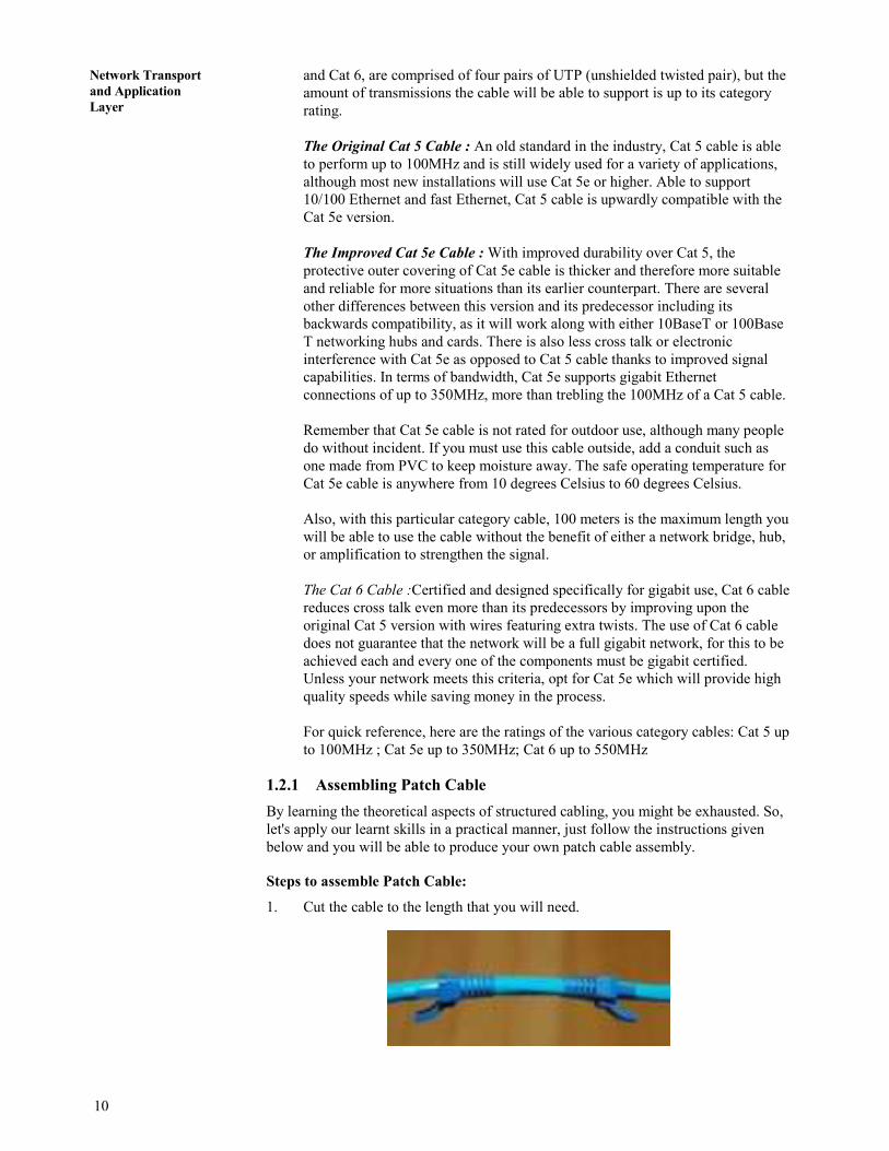
2. Skin the cable about 1.5” down.
3. Remove all of the twists in the cables pairs. Un-twist each pair, and straighten
each wire between the fingers.
4. Cat 6 cable has a center spine that needs to be removed. Pull on the spine and
fold the pairs back. Then cut the spine as close to the cables end as possible.
The process is shown in steps A,B,C,D to be executed sequentially
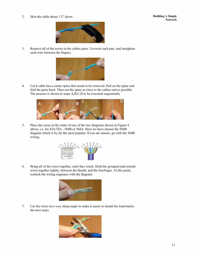
5. Place the wires in the order of one of the two diagrams shown in Figure 4
above, i.e. for EIA/TIA - 568B or 568A. Here we have chosen the 568B
diagram which is by far the most popular. If you are unsure, go with the 568B
wiring.
6. Bring all of the wires together, until they touch. Hold the grouped (and sorted)
wires together tightly, between the thumb, and the forefinger. At this point,
recheck the wiring sequence with the diagram.
7. Cut the wires on a very sharp angle to make it easier to install the load-bar(in
the next step).

12
Network Transport
and Application
Layer
8. Insert the loadbar on the wires one wire at a time.
This is why we recommended cutting the wires on an angle.
9. Check the wiring sequence one more time. Than slide the load bar down all the
way and make a straight cut about 0.25 past the loadbar. A perfectly straight cut
is essential here.
10. Insert the connector onto the loadbar assembly.
Hold the plug with the copper connectors up and the locking clip facing down.
In this configuration, the Brown Pair of wires should be to the right side
11. For Crimping, push the connector all of the way in and then squeeze down all
the way on the crimper. Remove the connector from the crimper body.
12. Repeat the procedure on the other end of the cable using the same wiring
diagram. NOTE: If you wish to make a crossover cable, than use the other
diagram (in this case 568-A)
13. Test the cable using a high quality four pair LAN cable tester.
Now you are perfectly ready to do structured cabling and design the network of
your own. To perform the structured cabling in a building or so you need to
refer to Figure 6, given below. It will clear your understanding, related to
structured cabling in big layouts, thus it relates to the role of structured cabling
in network design. The Figure 6 explains that, Once the connection from the

13
Building A Simple
Network
service provider is installed in the institutional premises, they left it with
connecting point, after which you are suppose to start your network. You are
required to connect a router to the point of connection given by service
provider, then output of the router is to be given to the network server which is
responsible for content management, bandwidth regulation, malware protection
etc. The output of the network server is connected to the switch with desired
number of ports. The switches are stored in the I/O boxes and the output of the
switch is cascaded with the other switches, which in turn are connected to the
wireless access points. Now in between the devices the paired cable, dully
connected with the connectors at both the ends is running. Nowadays patch
cords/cables, as per the standards are also available, but they are bit expensive.
In general, networking engineers purchases the cable bundle and crimp the RJ45
connectors at the ends of the cables through the crimping tool.
���� Check Your Progress 1
1. Differentiate between Straight Through Cable and Crossover Cable?
…………………………………………………………………………………….
…………………………………………………………………………………….
…………………………………………………………………………………….
2. Identify the suitable cable i.e. straight through/ crossover cable, required to
connect the following
a) Computer to Computer
b) Switch to Switch
c) Computer to Modem
d) Computer to Switch
e) Switch To Router
…………………………………………………………………………………….
…………………………………………………………………………………….
…………………………………………………………………………………….
1. connection
from
the
service
2.connect a router to the point
of connection given
by service provider,
then output of the
router is to be given
to the network server
3. output of the network server
is connected to the
switch, switches are
stored in the I/O
boxes and the output
of the switch is
4. switches, which in turn are
connected to the wireless
access points
CAT5/CAT6 Cables
Computer system connected
to the network
14
Network Transport
and Application
Layer
3. Differentiate between 10 Base T and 100 Base T - IEEE standards of twisted
pair cabling
…………………………………………………………………………………….
…………………………………………………………………………………….
…………………………………………………………………………………….
1.3 INTEGRATING HOME COMPUTERS
Electronic environment of any house involves wired or wireless connectivity among
various devices viz. computers themselves, between computers and printers, etc.
Since, you had already studied the concept of structured cabling, you are expected to
firstly understand “How the patch cables can be used to directly connect the
computers?” , then we will extend our discussion in the subsequent section, to let you
understand “How switches or Hubs can be used to connect the computer systems?”
and in the similar manner we will proceed for the development of wireless networks
too
So, let's start our discussion with “How to connect two computers simply by cross-
over cable (without router or switch)?”.The steps are listed below, just follow them
and you will get it done
1.3.1 How to Connect Two Computers by Using Cross-Over Cable?
This section involves the connectivity of the computers through a cross over cable,
without using the network devices like switch or hub. However we will discuss the
establishment of computer network by using the network devices in our subsequent
section 1.4.1. In this unit we are assuming that the user are having Windows operating
system .
STEPS
1. Switch ON the computers
2. Connect both computers with a cross over cable(Cat 5/6) having RJ 45
connector crimped at its both ends.
3. Go to control panel
4. Click on network connections
5. Right click on cable connections.
6. Click properties
7. Pick internet protocol (TCP/IP) & press properties.
8. Click on choose following IP address
IP address: 1 choose 192.168.1.1
9. Network is 255.255.255.0
10. Press ok and close
11. Now repeat the steps (1 to 10) on the other computer but choose different IP
address say it is 192.168.1.2
15
Building A Simple
Network
12. Now test the connection by using cmd command
• Go to start
• Click Run
• Type cmd
• Type ping IP address if you are on system with IP 192.168.1.1 (i.e. ping
192.168.1.2)
• If it says time-out, that means that you don’t have a connection with other
computer
Interconnectivity facilitates the data sharing among the computers. So,
you are required to understand, “How to share the data among the
computers, connected to each other in either mode i.e. wired or wireless ”
Just follow the steps listed below and you will get the data shared among
the computers, listed steps work for both wired and wireless connections.
1.3.2 How to Share Data Between Two Computers?
In this section we are going to exploit one of the basic need of computer network, i.e.
the sharing of data between the computers. The section gives you the stepwise
guidance, to perform the task of data sharing. In this unit we are assuming that the
user are having Windows operating system .
STEPS
1. Assign IP address to both computers (in the same manner as discussed above)
2. Go to control panel.
3. Choose network and internet option.
4. How choose network and sharing center option.
5. Choose manage network connections option.
6. Right click area connection and select properties option.
7. Select TCP/IPV 4 and click properties
8. Select “Use the following IP address” say it be 10.1.1.1,
say subnet mask is 255.0.0.0. now click ok.
9. Now click close.
10. Close the network connections window.
11. Close the network and sharing center window.
12. Close the network and internet option window.
13. Connect both computers by cable
a) for different devices: straight cable e.g Switch → Computer
b) for same devices: Cross over cable
14. Now you have to share folder or file that you want to access from other
computer
i) Create a folder say on desktop
16
Network Transport
and Application
Layer
ii) Right click the folder and choose properties
iii) Select the sharing tabs.
iv) Select the advanced sharing button.
v) Check the share this folder option.
vi) Press the permission button.
vii) Check the permission say full control/ Change/ Read to be allowed or
deny.
viii) Click the apply button for all opening you made in sharing section and
then finally close the sharing properties tab.
15. Turn file sharing ON.
a) Go to control panel.
b) Select network and sharing center.
c) Turn ON the file sharing option and click apply.
d) Choose the option “No make the network that I am connected to a private
network” if you don’t want data to be shared by All. Otherwise choose
“Yes, turn on file sharing for all public networks”.
e) For security you may activate the “Password protected sharing” by
turning ON the password protected sharing and click apply.
f) Now close all the windows/ tabs opened till the above task is done.
16. To access folder that you have shared
a) Go to other computer by typing //10.1.1.2
b) Select share folder icon
c) Create new folder and close the opened windows.
17. To get other computer on to your screen
a) Type or Run mstsc command in the search option.
b) Remote desktop option get activated.
c) Type the IP of the computers you want to connect to say 10.1.1.2 in the
computer section and click connect
18. Now you can share the data of 10.1.1.2
1.4 `
Till the moment you understood that a network could be as simple as two users
sharing information through a diskette or as complex as the Internet that we have
today. The Internet is made up of thousands of networks interconnected through
devices called hubs, bridges, routers and switches. These connecting devices are the
building blocks of a network and each of them performs a specific task to deliver the
information that is flowing in the network. So, it's time to learn how to connect the
computers by using these connecting devices. We will limit our discussion to hubs
and switches only, as they are widely used in developing LAN. So, let's understand
the devices and their utilities in brief.
HUB : A hub is a connecting device that all end workstations are physically
connected to, so that they are grouped within a common domain called a network
17
Building A Simple
Network
segment. A hub functions at the physical layer of the OSI model; it merely regenerates
the electrical signal that is produced by a sending workstation, It is a shared device,
which means if all users are connected to a 10Mbps Ethernet hub, then all the users
share the same bandwidth of 10 Mbps. As more users are plugged into the same hub,
the effective average bandwidth that each user has decreases.
SWITCH: Switch is another important device when we talk about computer network
on broader spectrum. It is used at the same place as hub is but the only difference
between the two is that switch possess switching table with in it. Switching tables
store the MAC addresses of every computer it is connected to and send the data to
only requested address unlike hub which broadcasts the data too all the ports.
NOTE:
1. A switch functions at the same OSI layer as the bridge, the data link layer. In
fact, a switch can be considered a multi-port bridge. While a bridge forwards
traffic between two network segments, the switch has many ports, and forwards
traffic between those ports. One great difference between a bridge and a switch
is that a bridge does its job through software functions, while a switch does its
job through hardware implementation. Thus, a switch is more efficient than a
bridge, and usually costs more.
2. Switches are introduced to partition a network segment into smaller segments,
so that broadcast traffic can be reduced and more hosts can communicate at the
same time. This is called micro segmentation, and it increases the overall
network bandwidth without doing major upgrade to the infrastructure.
3. Hub is Unmanaged device where as switch can be a managed or unmanaged.
Both support full duplex communication i.e. any computer can send data to any
other computer connected through the connecting device. The devices can have
4/8/16/32 ports and you may connect two or more than two switches or hubs, to
form the cluster of networks. To a N port hub/switch, one port may be used to
connect to the server and other N-1 ports may be used to connect the client
devices.
4. you are not desired to configure the HUB/SWITCH they got automatically
adapted to the networks, unlike the case of Routers and Access points where
you need to explicitly configure the network.
1.4.1 How to Connect Computers USING HUB / SWITCH ?
In section 1.3.1 we discussed How to connect computers using cross over cable?, in
this section we are extending the concept of the computers connectivity through
network devices like hub/switches. The steps desired to be performed are given
below:
1. Connect the hub to the power source through its adapter and switch it ON
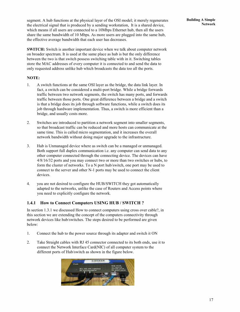
2. Take Straight cables with RJ 45 connector connected to its both ends, use it to
connect the Network Interface Card(NIC) of all computer system to the
different ports of Hub/switch as shown in the figure below.

18
Network Transport
and Application
Layer
3. Switch ON the computers
4. Go to control panel
5. Click on network connections
6. Right click on cable connections.
7. Click properties
8. Pick internet protocol (TCP/IP) & press properties.
9. Click on choose following IP address
10. IP address: 1 choose 192.168.1.1
Network is 255.255.255.0
11. Press ok and close
12. Now repeat the steps (1 to 10) on the other computer but choose different IP
address say 192.168.1.2 for second computer and so on.
13. Now test the connection by using cmd command
a) Go to start
b) Click Run
c) Type cmd
d) Type ping IP address if you are on system with IP 192.168.1.1 (i.e. ping
192.168.1.2)
e) If it says time-out, that means that you don’t have a connection with other
computer
1.4.2 How to Create Cluster OF Switches/Hubs ?
Let say you have a network at home, the Hub/Switch you bought only got 4 Ethernet
LAN ports. 2 ports are connected to computers and 1 port is connected to notebook.
You then found out you still have 1 computer and 1 notebook to connect to network,
but you only left 1 Ethernet LAN port on Hub/Switch, so how to connect both devices
to the network and solve this problem?
The solution is easy. You can create a network cluster by connecting one more
hub/switch to one of the ports of the existing hub/switch by using cross-over cable.
After that, you can connect computer and notebook to the switch’s normal port by
using straight cable, finally they are all connected to network and able to access
Internet. The LED on the switch will show you which ports are connected.
1.4.3 How to Configure a Wireless Network?
After going through the sections given above , you might have understood the efforts
involved in the development of any wired network. So, to simplify the complexities
of wired networks, the technology has explored the option of wireless network, which
involves one more network device i.e. Access Point. In this section we will let you
understand the configuration of wireless network. The steps to configure a wireless
network are given below :
1. Switch on the computer and Access point
2. Activate the wireless network mode of computers
19
Building A Simple
Network
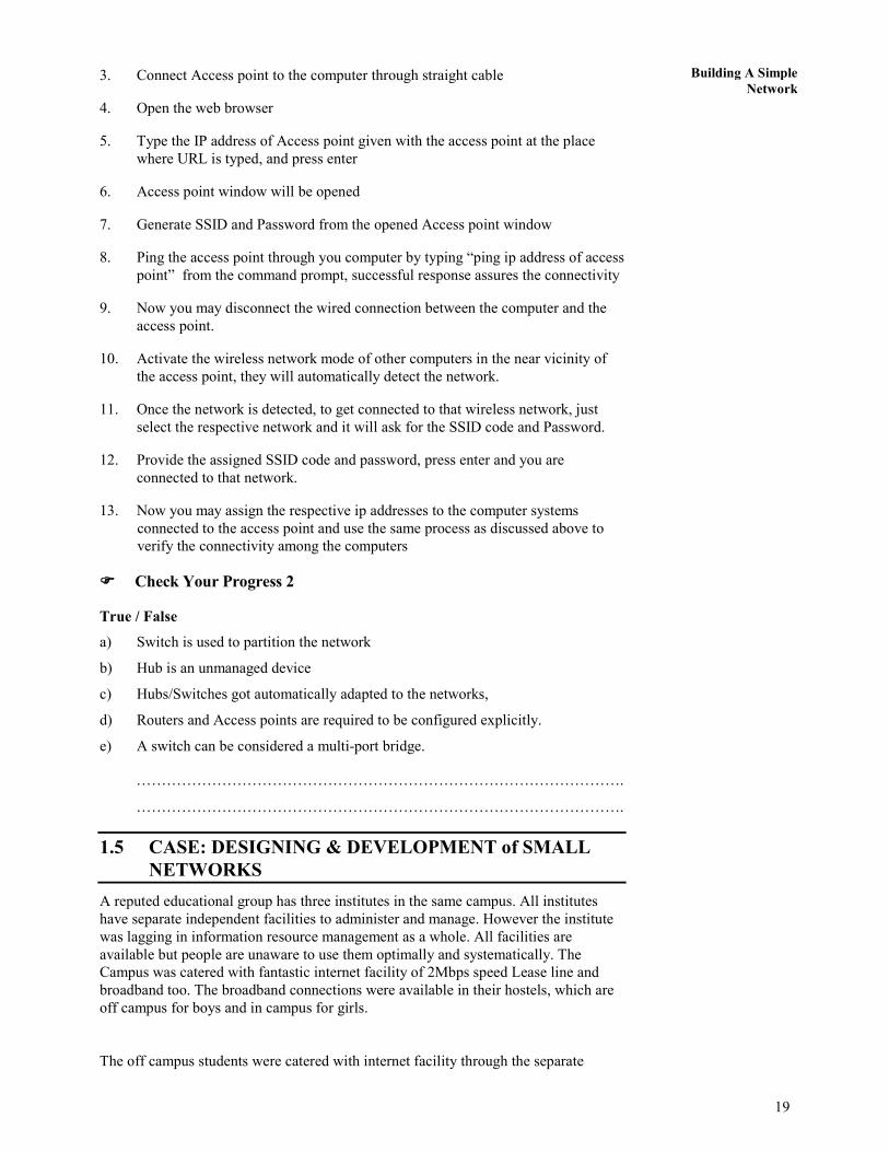
3. Connect Access point to the computer through straight cable
4. Open the web browser
5. Type the IP address of Access point given with the access point at the place
where URL is typed, and press enter
6. Access point window will be opened
7. Generate SSID and Password from the opened Access point window
8. Ping the access point through you computer by typing “ping ip address of access
point” from the command prompt, successful response assures the connectivity
9. Now you may disconnect the wired connection between the computer and the
access point.
10. Activate the wireless network mode of other computers in the near vicinity of
the access point, they will automatically detect the network.
11. Once the network is detected, to get connected to that wireless network, just
select the respective network and it will ask for the SSID code and Password.
12. Provide the assigned SSID code and password, press enter and you are
connected to that network.
13. Now you may assign the respective ip addresses to the computer systems
connected to the access point and use the same process as discussed above to
verify the connectivity among the computers
���� Check Your Progress 2
True / False
a) Switch is used to partition the network
b) Hub is an unmanaged device
c) Hubs/Switches got automatically adapted to the networks,
d) Routers and Access points are required to be configured explicitly.
e) A switch can be considered a multi-port bridge.
…………………………………………………………………………………….
…………………………………………………………………………………….
1.5 CASE: DESIGNING & DEVELOPMENT of SMALL
NETWORKS
A reputed educational group has three institutes in the same campus. All institutes
have separate independent facilities to administer and manage. However the institute
was lagging in information resource management as a whole. All facilities are
available but people are unaware to use them optimally and systematically. The
Campus was catered with fantastic internet facility of 2Mbps speed Lease line and
broadband too. The broadband connections were available in their hostels, which are
off campus for boys and in campus for girls.
The off campus students were catered with internet facility through the separate

20
Network Transport
and Application
Layer
broadband connection, which were generally tempered by the students residing there
and hence connectivity problem was a regular feature, apart from this the occupancy
of the hostel was approx 27 students, nine students at each floor and a connection is
available at ground and second floor, the third floor students are sharing the
connection with the broadband connection available at second floor. As 18 students
got attached to one connection the speed of internet got considerably decreased, so the
students contacted the IT department for a solution. The problem was expected to be
solved without going for a separate broadband for third floor.
However the in campus, girls hostel was enjoying the uninterrupted internet access
because the 2Mbps speed was directly at their disposal. The students here were using
it generally for chatting, movie download, torrents etc. and the purpose was not at all
academic. As many movies, software and other downloadable contents were put in
process of download, the actual working of entire campus was hampered. The internet
speed was drastically reduced and sometimes it got choked too, thus entire campus
was suffering.
The IT situation was pathetic in the sense that other departments were not at all
utilizing the existing resources in the sense, the Computer Lab as a whole was on
WIFI and the systems deployed there were desktops; the accounts section was taking
data backup on CDs. The faculties were using pen drives to carry their presentation to
the classes which actually let VIRUSES to enter into the network and hence the
systems need frequent maintenance. The students who participates in the lab sessions
frequently complaints that on which ever system they worked in the last class they are
unable to get that computer system in the subsequent class and as a result the tasks
executed in the previous class are non traceable. Apart from this the students were
also equipped with laptops and entire campus is WIFI, the students have a regular
practice to change their IP addresses assigned to them by IT department as a result of
which IP conflict occurs and it leads to create problems in accessing the internet for
other students too.
The internet service provider is a reputed organization , providing sufficiently nice
services but generally because of the excavation process and other tasks performed by
other companies in real estate or so, the cables required to provide internet services
in the institute campus are damaged hence working/communication of entire institute
is disturbed. IT manager was expected to resolve this issue too. Apart from this
problem, the institute is in expansion mode and frequently new EPABX numbers are
desired with a traceability that how many lines are making calls outside the campus
and their billing was also expected to be maintained and informed to the accounts
section for necessary actions. Sometimes the faculties are on leave and their lecture
suffers, it was desired by management to make some arrangements that , faculty
should be able to deliver the lecture even when he/she is out station. Institute was
planning to develop this facility of video lectures to use for conferences or so, to be
organized in the campus. After all, institute need to have internet website/intranet
website and extranet facility to facilitate the employees working even from outside.
After going through the case given above, you might have realized the presence and
importance of networking in our day to day life. Apart from this you might have
identified various network components required to establish the computer network.
Since you had already gone through various networking concepts in the previous units
of this course BCS 041, you are required to make yourself comfortable, to do the
tasks given below
ASSIGNED TASKS:
TASK-1 Being an IT manager of the Institute, Identify the problem areas and
problems specific to the identified area in the institute. Present your identified

21
Building A Simple
Network
problems in a tabular format.
TASK-2 Identify solutions (both hardware and software), which may be used to
resolve the identified problems. Identify the cost effective solution you wish to
implement, justify your choice with suitable arguments.
TASK-3 Prepare a summarized requirement report, targeting the identified problem
with the proposed solution, in the form of a table, so as to simplify decision making at
management end.
SOLUTIONS TO THE ASSIGNED TASKS
Lack of knowledge related to networking and related techniques is the prime cause of
problems in the entire campus of the educational institution. Technical Workforce of
the institute is unaware of network devices and their usage viz.
1. where to go for wired networking and where for wireless networking
2. which servers are to be designed viz. DNS, Backup server etc
3. non awareness of firewalls or content filtering software
4. how to administer the network connection directly coming from the service
provider.
Apart from the mentioned lacunas in the existing network of the campus, there are
many more deficiencies; we will discuss them as the discussion proceeds.
From the given Case, we identified following problems persists, in the respective
areas and sub areas :
1. Entire Campus :
a) The connectivity from service provider is wired connectivity, as a result
of which as and when the connection cable got damaged due to
excavation the entire campus got disconnected from the internet services.
b) The bandwidth distribution is open in the sense, the lease line from the
service providers router is directly catering the institutes access points,
thus the bandwidth can be used by the persons outside the institutional
premises, and this is quite unsafe because someone it’s a security abuse
for the institutional network.
c) Further, the usage of bandwidth by outsiders leads to network choking i.e.
network hangout.
d) Students equipped with laptops were changing the ip addresses, thus ip
conflict is a frequent issue of the respective network.
e) No Intranet or extranet web facility, total reliance on Internet. Thus, in
the absence of Internet connectivity, entire communication is on standby
mode.
f) Comparatively low bandwidth, as desired for video conferencing or
online lectures.
2. Hostel :
a) On Campus Hostel :
Since there is no control over the bandwidth regulation, the users are
consuming the available bandwidth for non – academic jobs, viz. online

22
Network Transport
and Application
Layer
gaming, movies download etc.
b) Off Campus Hostel :
i) The Internet connectivity is given through broadband connection,
the positioning of the broadband device is not safe, thus the users
were able to hack the device password by using hacking software
by directly connecting their systems to the broadband device
through the network cable.
ii) The broadband connection was overloaded, thus the Internet speed
is slowed down.
3. Computer Lab. :
a) Just to save the cost of wiring the entire laboratory systems were on
wireless connectivity through the access points, I agree its cost effective,
but at the time of lab maintenance and up gradation, the situation become
quite challenging, because the network speed is quite slow in wireless
mode. Apart from this if connection is lost in between the software
installation, then entire file gets corrupt.
b) Since it is very much impossible to find the seat on the same computer
system in the subsequent class, the students are to redo the task performed
in previous session. Thus the students are unable to recollect the data or
the task executed in their past classes.
c) Usage of flash memories/pendrives for porting the data, leads to virus
prone network.
4. Accounts Section :
a) The backup is taken on the CD/DVDs. if prior to take the backup, system
crashes out, and then nothing can be done.
We know that if the problems are identified then half of the job is done.
So, its time to talk about solutions and related alternatives, further we are suppose to
identify the optimal and feasible solution.
Network solutions are proposed in the sequence, the problems are identified above
As per the identified problem following are the requirements for troubleshooting.
Hardware: Gigabit Ethernet cards, Cat 6 cables, servers (Domain name Server,
Backup server),Online Ups for servers, switches, I/O boxes, Connectors, LAN meter,
Crimping tools etc.
Software: Proprietary or Open source server software, content filtering software,
Bandwidth regulator , Anti- malware software, or Software Firewall.
Let's see how above mentioned resources should be utilized in network designing and
development, such that the identified problems of respective identified areas are
solved. First, let's start from the Campus Related issues.
Identified Network Solution for identified areas and sub areas:
1. Entire Campus :
a) Solution to connectivity problem: The campus should have wireless lease
line and not the wired one or may have both types, because wired
connectivity has its own advantage related to the speed of operation.
23
Building A Simple
Network
b) Solution to bandwidth distribution: Instead of directly connecting the
access points to the service provider connection available through their
router. The Network Input/output mechanism should be laid by using the
Gigabit Ethernet cards, where the cards are installed on the motherboard
slots of the computer system, such that connection from the service
provider router goes to the input cards and the output card is connected to
the access points through the switches. In between the input and the
output card, respective software works viz. open source content
management software like squid, software firewalls, anti viruses, anti
spyware, anti spam software etc, thus the connection is secure and well
regulated. Actually, this computer system acts as a server, which is
responsible for bandwidth regulation, content management etc.
c) Solution to usage of bandwidth by outsiders : The router should be
protected by necessary SSID(Service Set Identifier) number and
password protection mechanism, which prevents outsiders from accessing
the network connectivity.
d) Solution to ip conflict: To get rid of the ip conflict problem, we may bind
the allotted ip address with the Mac id of the laptop OR we may keep the
administrative rights with the system administrator and let the student to
act as a user, so no permissions are available to change the ip address.
e) Solution to total reliance on Internet: The institute must design at least a
mail server, such that the in campus communication goes on without
hindrance. Further, they should design an intranet website, because
everything cannot be for public domain.
f) Low Bandwidth: Bandwidth requirement is to be reworked as per the
usage, and the connection capacity is to be revised from 2 mbps to the
required one.
2. Hostel :
a) On Campus Hostel :
Since the on campus hostel is very much in premises so the solution to
the bandwidth distribution discussed above, solves this problem. The
software firewall have the feature to allot the bandwidth to the particular
series of ip addresses which may be allotted to the students or teachers,
they are having many other options too.
b) Off Campus Hostel :
i) Broadband connection safety: The broadband device should be
protected by installing an I/O Box, mounted close to ceiling, thus
the students cannot access the port connections of the broadband
device.
ii) Overloaded broadband connection: Two solutions are possible;
either we should go for one more broadband connection, which
incurs a recurring cost to the institution. The other solution is that
we install a switch for the top floor of the hostel where wired
connectivity is provided, this involves one time cost of switch
and cabling, further the advantage of mobility is curtailed.
3. Computer Lab. :
a) It is advised that the computer labs should have wired connectivity

24
Network Transport
and Application
Layer
because, wired network has better speed then wireless network. Apart
from the speed the connection is dedicated, thus the possibility of losing
network connection, in between the process of installation or so, is rare.
We may be using the labs for exam purpose or so, in that situation loss of
connectivity or so leads to tremendous problems. I agree that the wireless
connectivity is quite manageable and cost effective, but at the time of lab
maintenance and up gradation, the situation become quite challenging,
because the network speed is quite slow in wireless mode. Apart from
this if connection is lost in between the software installation, then entire
file got corrupt. So, Labs should have wired connectivity
b) Recollecting the data: Here is the requirement to design a DNS (Domain
Name Server), where some memory space is allotted to each student,
which may be according to their roll numbers or so. Thus through DNS,
students are always able to work in their allotted space, and can recollect
the job done in previous class. But, there is a requirement of On-Line Ups
with the DNS server, because if the power goes Off, then restart of DNS
is time consuming
c) Data Portability: Again DNS will be the solution for accessibility of data
in class rooms or labs or anywhere else, thus we can block the USB ports
and let the entire network be managed through DNS and Intranet.
4. Accounts Section :
a) Backup on CD/DVDs : A Backup server is desired to be designed for
solving this problem.
1.6 SUMMARY
After going through this unit you are now equipped with the skills desired to structure
a wired or wireless computer network. Now you are required to make practice of the
learned concepts and realize the facts and figures of networking. Here you learned the
concepts related to the Structure Cabling which is further extended to the skill based
assembling of Patch Cables, which are widely required to connect computers and
network devices, in a wired network. The concepts of wired network are covered
under the heading integrating home computers, which enables us to understand the
concepts related to How to connect two computers by using crossover cable? and
How to share data between two computers? The unit also explored the creation of a
small network in both wired and wireless mode, by using hubs, switches and access
points. The understanding of the concepts learned in this unit, enabled your
application skills through a case given in the end. Hope, you are in the position to
apply the learned concepts.
1.7 SOLUTIONS / ANSWERS
���� Check Your Progress 1
1. The straight-through cables are used when connecting Data Terminating
Equipment (DTE) to Data Communications Equipment (DCE), such as
computers and routers to modems (gateways) or hubs (Ethernet Switches). The
cross-over cables are used when connecting DTE to DTE, or DCE to DCE
equipment; such as computer to computer, computer to router; or gateway to
hub connections. The DTE equipment terminates the signal, while DCE
equipment does not.
2. a) Computer to Computer – Crossover
b) Switch to Switch – Crossover
25
Building A Simple
Network
c) Computer to Modem – Straight Through
d) Computer to Switch – Straight Through
e) Switch To Router – Both (if problems, go
with Crossover)
3. 10Base-T and 100Base-T are the IEEE (Institute of Electrical and Electronics
Engineers) standards defining the electrical and physical characteristics of
twisted-pair cabling for use in 10 Mbps (Megabits per second) and 100Mbps
Ethernet connections. The “T” stands for Twisted pair, and these two Ethernet
connections use wire pairs 2 and 3 to transmit and receive information,
corresponding to the orange and green twisted pair Nowadays we use the
Gigabit Ethernet (or 1000Base-T), where all four conductor pairs, are used to
transmit and receive information simultaneously.
���� Check Your Progress 2
True / False
a) True
b) True
c) True
d) True
1.8 REFERENCES
WEBLINKS
• http://www.andcable.com/files/UnderstandingEthernetPatchCords.pdf
• http://en.wikipedia.org/wiki/Structured_cabling
• http://www.lanshack.com/make-cat5E.aspx
• http://www.iplocation.net/tools/rj45-wiring.php
EBOOKS
• Cisco Networking Academy Program CCNA 1: Networking Basics v3.1
• IP Network Design Guide from IBM by Martin W. Murhammer, Kok-Keong
Lee, Payam Motallebi,Paolo Borghi, Karl Wozabal

26
Concepts of
Communication and
Networking
Network Transport
and Application
Layer
UNIT 2 INTRODUCTION TO NETWORK
ARCHITECTURES
Structure Page No.
2.0 Introduction 26
2.1 Objectives 26
2.2 X.25 Architecture 26
2.3 Atm Network 28
2.4 IPv4 and IPv6 Overview 41 2.4.1 Classes of IP Address
2.5 Summary 45
2.6 Solutions/Answers 45
2.0 INTRODUCTION
In the simplest form, data transfer can take place between two devices which are directly
connected by some form of communication medium. But it is not practical for two
devices to be directly point to point connected, because of two reasons (i) the devices
are very far apart and (ii) there is a set of devices, each of whom may require to connect
to others at various times. Solution to this problem is to connect each device to a
communication network. As you know computer networks means interconnected set of
autonomous computers, in order to meet the needs of various applications, networks are
available with different interconnection layouts and plans, methods of access, protocols
and data carrying capacities. Network architecture is a complete design of a
communications network. Primarily we can say that it is a framework for the
specification of a network's physical components, their functional organization and
configuration. Network architecture also includes the operational principles and
procedures. This unit is an introduction to network architecture, in which we will
discuss about different network architectures like X.25, Frame Relay, ATM. Further, it
covers IPv4 and IPv6 protocol details; we will also discuss the mechanisms for
implementing/deploying IPv6.
2.1 OBJECTIVES
After going though this unit, you should be able to:
• Understanding the working of various Network architectures
• differentiate between X.25, Frame Relay and ATM Architecture
• Know the functions of X.25, Frame Relay and ATM layers
• describe how X.25, Frame Relay and ATM protocols works;
• Know the need of IPv6 protocol
• Compare between the IPv4 and IPv6
2.2 X.25 ARCHITECTURE
Before discussing about X.25, we will refresh our knowledge about switching
techniques. As you may know following are the basic switching techniques:
Circuit Switching: Circuit switching is used in the telephone networks to transmit
voice and data signals. To enable synchronised transmission, circuit switching
establishes a dedicated connection between the sender and receiver involved in the
data transfer over the network. As a result, the connection consumes network
27
Introduction to Network
Architectures capacity whether or not there is an active transmission taking place; for example, the
network capacity is used even when a caller is put on hold.
Packet Switching: In contrast to circuit switching, packet switching ensures that the
network is utilised at all times. Data to be sent is broken down into chunk of bits or
packets. Each packet contains data and header information for control. At each node the
packet is received, stored briefly and passed on. At each node the packets may be put on
a queue for further movement into the network. It does this by sending signals even in
the small unused segments of the transmission — for example, between the words of a
conversation or when a caller is put on hold. There are two approaches to the above kind
of transport:
1. Datagram, where each packet can take any path through the network as long as
they all reach the destination.
2. Virtual Circuit, where all the packets are routed through the same path without
having the path dedicated. The path segments may carry many virtual circuits.
Datagram allows for dynamic handling of congestion and no call setup is
necessary. Virtual circuits allow for sequencing, error and flow control.
X.25 is an old standard protocol suite for packet based wide area network. The old
networks mainly telecommunications companies and ATM’s (automated teller
machines) were following X.25 protocols for packet switching based network. These
WAN’s are having packet-switching exchanges and leased communication channels. At
present X.25 protocols has been replaced by other better and less complex protocols of
TCP/IP suit however, the service is still in use and functioning in some places and
applications. Some student are interested to know that why it is called with such name
X.25? The reason is International Telecommunication Union (ITU) publishes some
series of technical books, among these technical books; there is a larger set of X-Series
specifications on public data networks. The X.25 specification is only a part of that X-
Series specification on public data networks.
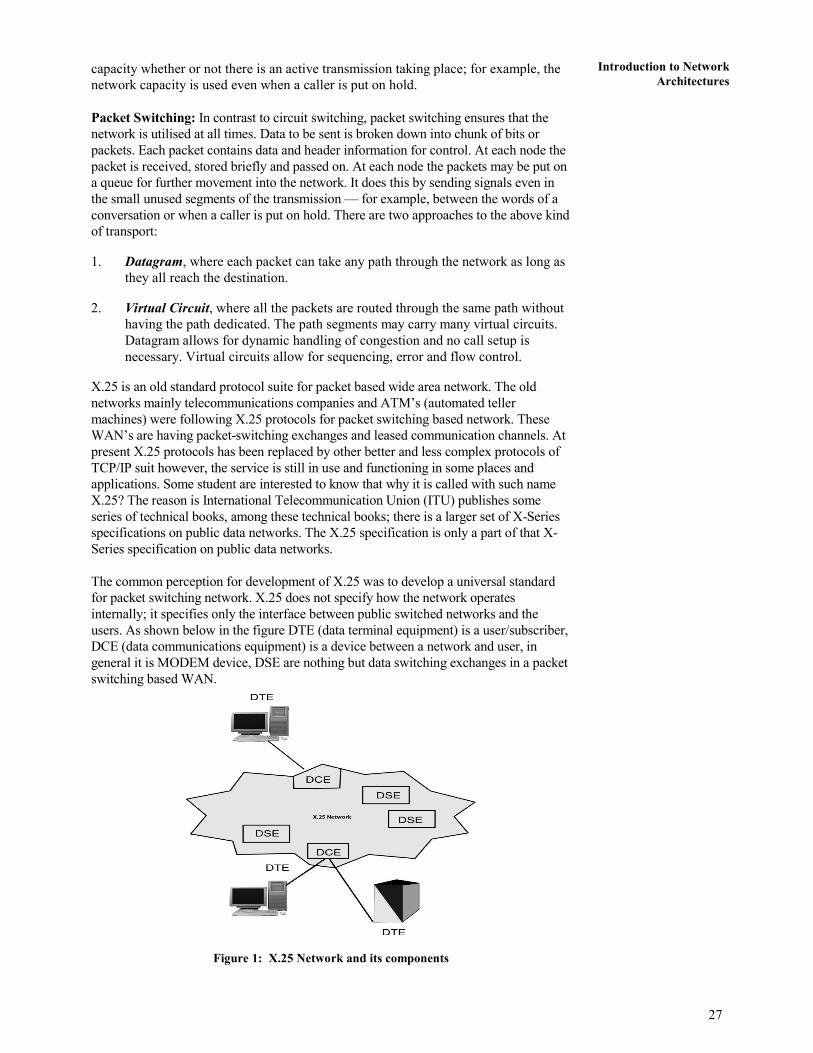
The common perception for development of X.25 was to develop a universal standard
for packet switching network. X.25 does not specify how the network operates
internally; it specifies only the interface between public switched networks and the
users. As shown below in the figure DTE (data terminal equipment) is a user/subscriber,
DCE (data communications equipment) is a device between a network and user, in
general it is MODEM device, DSE are nothing but data switching exchanges in a packet
switching based WAN.
Figure 1: X.25 Network and its components

28
Concepts of
Communication and
Networking
Network Transport
and Application
Layer
X.25 is specified on 3 layers:
1. Physical layer
2. Data link layer
3. Network layer
X.25 Network provides the means for these users (DTE) to communicate with each
other. In the context of X.25 Data link and Network Layers, an X.25 DCE is the local
network node to which the DTE is connected. The X.25 protocol defines the rules for
the communication between the DTE and the DCE. You may again note that
communication within the WAN may be entirely by some other mechanism. Following
are details of each layer of X.25:
• Physical layer: Specify the physical, electrical and interface between host and
network. It also specifies functional and procedural characteristics to control the
physical link between a DTE and a DCE. Common implementation is
X.21protocol.
• Data link layer: Deal with data transmission over an between user equipment
and routers. Error control and flow control are its main responsibilities. This
layer consists of the link access procedure for data interchange on the link
between a DTE and a DCE.
• Network layer: this layer specify a packet-layer protocol for exchanging control
and user data packets to form a packet-switching network based on virtual calls.
It has main functions like Addressing, Flow control, Delivery confirmation, etc.
Also, it allow to established Virtual Circuit and send packet reliably.
X.25 is connection oriented architecture and support switched virtual circuits (SVC) and
permanent virtual circuits (PVC). Switched virtual circuits are established on the need
basis. SVC is established when a call is made and broken down after the call is
completed. On the other hand, permanent virtual circuits are almost leased kind of
connections, which provide a dedicated connection between DTE’s. X.25 sessions are
established when one DTE device contacts another to request a communication session.
The DTE device that receives the request can either accept or refuse the connection. If
the request is accepted, the two systems begin full-duplex information transfer. Either
DTE device can terminate the connection. After the session is terminated, any further
communication requires the establishment of a new session.
2.3 FRAME RELAY
Frame Relay is a virtual-circuit based WAN that was designed to provide more efficient
transmission scheme than X.25. It provides connection oriented services at reasonable
speed and low cost. Interestingly in Frame relay, the packets are now of variable length
(called as frame, which is a reason such architecture is named FRAME RELAY) with
less overheads. Some of the main drawbacks of X.25 are as follow:
1. X.25 has a low 64 kbps data rate, [In 1990 It was very less]
2. X.25 has extensive flow Central and error central at both the data link and
network layer (Because in 1970-80 available media was more prone of these
errors and an objective of X.25 was to develop a global system which may have
more possibility of errors). It creates large overhead and slow transmission.
3. X.25 was designed for private use, not for Internet (public use). It has its awn
network layer and Internet has its awn hence packet is encapsulated in X.25 and
than Internet, which increase overheads.
29
Introduction to Network
Architectures Frame relay overcome from the above drawbacks. It is a wide Area Network (WAN)
with following features:
1. It operates a higher speed (1.5 mbps, and 44.376 mpbs)
2. Frame relay operates in only physical and data link layer. (so it can easily be
used as backbone network to other protocols have network layer with less
overheads)
3. Frame Relay allows bursty data. It means if at some point large amount of data
is sent by someone than network should able to handle it properly.
4. Frame relay allow a Frame size of 9000 bytes, which can accommodates all
LAN Frame sizes
5. It is less expensive than previous WANs, particularly with X.25.
6. It has error detection at data link layer only.
• No Flow control, No error control, No re-transmission policy.
• If frame is damaged, it is dropped.
Now can you answer why Frame Relay is faster than X.25? The answer is given above
because it has fewer overheads of error control and flow control.
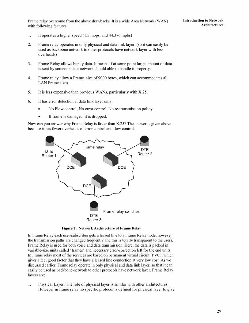
Figure 2: Network Architecture of Frame Relay
In Frame Relay each user/subscriber gets a leased line to a Frame Relay node, however
the transmission paths are changed frequently and this is totally transparent to the users.
Frame Relay is used for both voice and data transmission. Here, the data is packed in
variable-size units called "frames" and necessary error-correction left for the end units.
In Frame relay most of the services are based on permanent virtual circuit (PVC), which
gives a feel good factor that they have a leased line connection at very low cost. As we
discussed earlier, Frame relay operate in only physical and data link layer, so that it can
easily be used as backbone-network to other protocols have network layer. Frame Relay
layers are:
1. Physical Layer: The role of physical layer is similar with other architectures.
However in frame relay no specific protocol is defined for physical layer to give

30
Concepts of
Communication and
Networking
Network Transport
and Application
Layer
flexibility and better connectivity with other architectures. It supports any of the
protocol recognized by ANSI. (American National Standard Institute)
2. Data Link Layer: Frame Relay uses simple protocol that does not support Flow
Control, error Control, only it has error detection mechanism. However, the
error correction is left for the end-user machines.
Format of Frame
Each Frame Relay Protocol data unit (PDU) consists of the following fields:
8 16 variable 16 8
Flag Address Informatio
n
….
FCS Flag
Start and End Flag: Flag Field is 8 bit size, used to perform “synchronization” which
indicates the beginning and end of the frame. Please refer to the unit 1 of block 1, where
we have given similar example of start and end bits used for asynchronous
communication. But what will happen if the flag bit pattern which we are using for end
or start a communication occurs in between the flags. To avoid it we use bit stuffing and
de-stuffing procedures at the source and destination respectively.
Frame Check Sequence (FCS): This is a 16 bits Field, which carries 16 bits of cyclic
redundancy check (CRC) used at each switching node in the network for error detection.
Information: This field is a variable size field because user can send any data bits in
this field. This is the actual data which network will pass on to receiver.
Address: This is a 16 bit or 2 bytes field having following fields inside of address:
DLCI C/R EA DLCI FECN BECN DE EA
6 1 1 4 1 1 1 1
DLCI: Data link connection identifier used to identify virtual circuit in the Frame
Relay.
DLCI field is of 10 bit size placed at two positions in the address field as given below:
i) The 1st DLCI is the 6 bits of first Bytes of address field
ii) The 2nd DLCI is the first 4 bits of second Bytes of address field
Command/Response (C/R): This is a 1 bit field. It is provided for upper layers to
identify whether “a frame” is a command or a response. (This is not for Frame Relay)
Extended Address: This is 1 bit field, which inform the protocols about the address,
such as:
• If, EA = 0 : Another address byte is to follow.(extended address can be 24 bit
or 32 bit)
• If, EA = 1 : Current byte is the final address
FECN (Forward Explicit Congestion Notification): FECN bit can be set (“1”) by
any switch of the network to indicate that traffic is congested in the frames travelling
towards the destination machine. This bit informs the destination that congestion has
occurred, so destination should is ready for delay or packet loss.
31
Introduction to Network
Architectures BECN (Backward Explicit Congestion Notification): BECN bit also indicate
congestion in a Network. BECN bit can be set (“1”) by any switch of the network to
indicate that traffic is congested in the frames travelling towards the source machine.
This bit informs the sender machine that congestion had occurred in the network,
hence slow-down the processing to prevent further delay or packet loss.
Discard Eligibility (DE): This is a 1 bit field, which indicates the priority of a frame.
Sometime, switches have to discard frame (like congestion). If DE is set to “1”,
switch may discard the frame in problematic situation else it is very important frame
and should not be discarded.
Frame Relay switching:
Here is an example of switching being done in the frame relay switch:
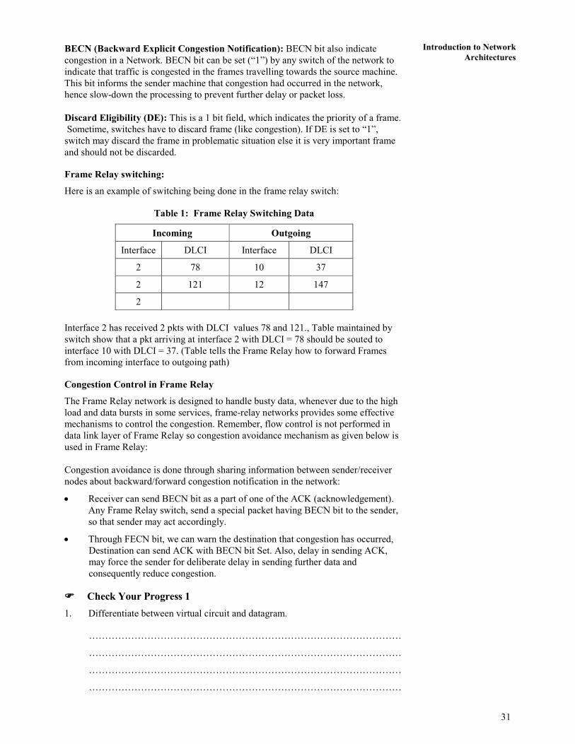
Table 1: Frame Relay Switching Data
Incoming Outgoing
Interface DLCI Interface DLCI
2 78 10 37
2 121 12 147
2
Interface 2 has received 2 pkts with DLCI values 78 and 121., Table maintained by
switch show that a pkt arriving at interface 2 with DLCI = 78 should be souted to
interface 10 with DLCI = 37. (Table tells the Frame Relay how to forward Frames
from incoming interface to outgoing path)
Congestion Control in Frame Relay
The Frame Relay network is designed to handle busty data, whenever due to the high
load and data bursts in some services, frame-relay networks provides some effective
mechanisms to control the congestion. Remember, flow control is not performed in
data link layer of Frame Relay so congestion avoidance mechanism as given below is
used in Frame Relay:
Congestion avoidance is done through sharing information between sender/receiver
nodes about backward/forward congestion notification in the network:
• Receiver can send BECN bit as a part of one of the ACK (acknowledgement).
Any Frame Relay switch, send a special packet having BECN bit to the sender,
so that sender may act accordingly.
• Through FECN bit, we can warn the destination that congestion has occurred,
Destination can send ACK with BECN bit Set. Also, delay in sending ACK,
may force the sender for deliberate delay in sending further data and
consequently reduce congestion.
���� Check Your Progress 1
1. Differentiate between virtual circuit and datagram.
……………………………………………………………………………………
……………………………………………………………………………………
……………………………………………………………………………………
……………………………………………………………………………………
32
Concepts of
Communication and
Networking
Network Transport
and Application
Layer
2. Compare between SVC and PVC of X.25?
……………………………………………………………………………………
……………………………………………………………………………………
……………………………………………………………………………………
……………………………………………………………………………………
3. Write any four differences between X.25 and Frame Relay.
……………………………………………………………………………………
……………………………………………………………………………………
……………………………………………………………………………………
……………………………………………………………………………………
4. Explain the used of FECN and BECN in Frame Relay.
…………………………………………………………………………………
……………………………………………………………………………………
……………………………………………………………………………………
……………………………………………………………………………………
2.4 ATM NETWORK
Asynchronous Transfer Mode (ATM) is a form of data transmission that allows
voice, video and data to be sent along the same network. In contrast to ATM, in the
past, voice, video and data were transferred using separate networks. For example,
voice was transmitted over the phone, video over cable networks and data over an
internet work. ATM has its similarities with the frame relay, particularly in the term
of data unit size, frame replay used a variable lengh data unit called frame. On the
contrary, ATM used fixed data unit named as “cell”, we can say ATM as Cell-Relay
in analogy to frame relay.
ATM was emerged as a viable technology for effective transmission of voice, video
and data. Some of its features are:
• ATM is a packet network like X.25, frame relay.
• ATM integrates all different types of traffic into one network.
• ATM supports multiplexing of multiple logical connections over single physical
channel.
• ATM does not provide flow Control and error control at data link layer.
• ATM can serve as a LAN or WAN backbone without requiring any network
replacement.
• ATM can be used in existing physical channels and networks. Because ATM
was developed to have such a wide range of compatibility with existing
networks, its implementation does not require replacement or over-building of
telephone, data or cable networks. It is also compatible with wireless and
satellite communications.
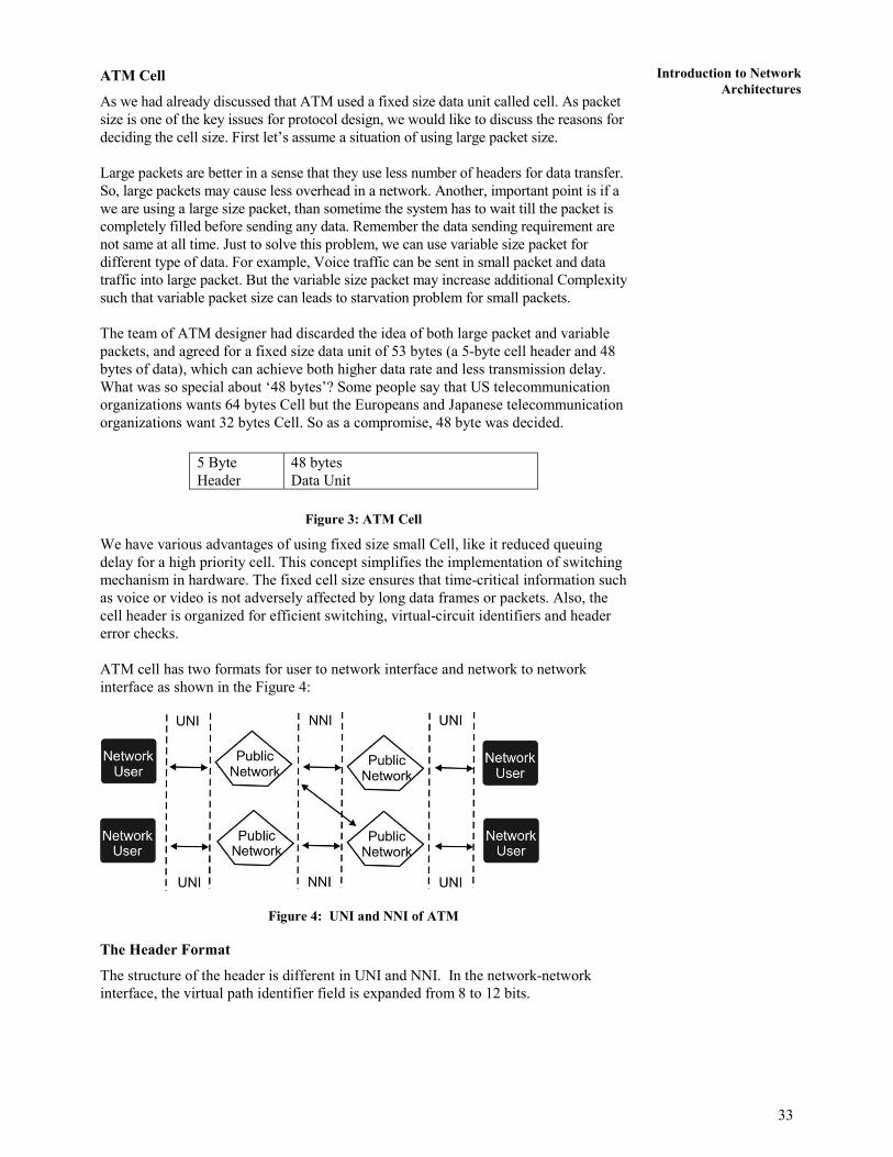
33
Introduction to Network
Architectures ATM Cell
As we had already discussed that ATM used a fixed size data unit called cell. As packet
size is one of the key issues for protocol design, we would like to discuss the reasons for
deciding the cell size. First let’s assume a situation of using large packet size.
Large packets are better in a sense that they use less number of headers for data transfer.
So, large packets may cause less overhead in a network. Another, important point is if a
we are using a large size packet, than sometime the system has to wait till the packet is
completely filled before sending any data. Remember the data sending requirement are
not same at all time. Just to solve this problem, we can use variable size packet for
different type of data. For example, Voice traffic can be sent in small packet and data
traffic into large packet. But the variable size packet may increase additional Complexity
such that variable packet size can leads to starvation problem for small packets.
The team of ATM designer had discarded the idea of both large packet and variable
packets, and agreed for a fixed size data unit of 53 bytes (a 5-byte cell header and 48
bytes of data), which can achieve both higher data rate and less transmission delay.
What was so special about ‘48 bytes’? Some people say that US telecommunication
organizations wants 64 bytes Cell but the Europeans and Japanese telecommunication
organizations want 32 bytes Cell. So as a compromise, 48 byte was decided.
Figure 3: ATM Cell
We have various advantages of using fixed size small Cell, like it reduced queuing
delay for a high priority cell. This concept simplifies the implementation of switching
mechanism in hardware. The fixed cell size ensures that time-critical information such
as voice or video is not adversely affected by long data frames or packets. Also, the
cell header is organized for efficient switching, virtual-circuit identifiers and header
error checks.
ATM cell has two formats for user to network interface and network to network
interface as shown in the Figure 4:
Figure 4: UNI and NNI of ATM
The Header Format
The structure of the header is different in UNI and NNI. In the network-network
interface, the virtual path identifier field is expanded from 8 to 12 bits.
5 Byte
Header
48 bytes
Data Unit

34
Concepts of
Communication and
Networking
Network Transport
and Application
Layer
8 7 6 5 4 3 2 1
Generic Flow Control* Virtual Path Identifier
Virtual Path Identifier Virtual Channel Identifier
Virtual Channel Identifier
Virtual Channel Identifier Payload Type ID CLP
Header Error Control
Figure 3: User-network Interface
8 7 6 5 4 3 2 1
Virtual Path Identifier
Virtual Path Identifier Virtual Channel Identifier
Virtual Channel Identifier
Virtual Channel Identifier Payload Type ID CLP
Header Error Control
INFORMATION PAYLOAD (48 Bytes)
Figure 4: Network-network interface
Let’s now look at the characteristics of each of the fields of the header format of an
ATM cell.
Generic Flow Control (GFC)
The GFC field of the header is only defined across the UNI and does not appear in the
NNI.
Function
• It controls the traffic flow across the UNI.
Virtual Path Identifier (VPI)
The VPI is an 8-bit field for the UNI and a 12-bit field for the NNI.
Function
• It constitutes a routing field for the network and is used to identify virtual paths.
In an idle cell, the VPI is set to all 0’s.
• Together with the Virtual Channel Identifier, the VPI provides a unique local
identification for the transmission.

35
Introduction to Network
Architectures Virtual Channel Identifier (VCI)
It is a 16-bit field used to identify a virtual channel. For idle cells, the VCI is set to all
0’s.
Function
• It functions as a service access point and it is used for routing to and from the
end user.
• Together with the Virtual Path Identifier, the VCI provides a unique local
identification for the transmission.
Payload Type Identifier (PTI)
The PTI field indicates the type of information in the information field. The value in
each of the three bits of PTI indicate different conditions.
• Bit 1 is set to 1 to identify operation, administration, or maintenance cells (i.e.
anything other than data cells).
• Bit 2 is set to 1 to indicate that congestion was experienced by a data cell in
transmission and is only valid when bit 4 is set to 0.
• Bit 3 is used to convey information between end-users.
Cell Loss Priority (CLP)
The 1-bit CLP field is used for indication of the priority of the cell. It is used to
provide guidance to the network in the event of congestion. When set to value 1, it
indicates that the cell may be discarded within the network when congestion occurs.
When the CLP value is set to 0, it indicates that the cell is of relatively high priority
and should be discarded only in situations when no alternative is available.
Header Error Control (HEC)
Each ATM cell includes an 8-bit HEC that is calculated based on the remaining 32
bits of the header.
Function
• It detects all single-bit errors and some multiple-bit errors. As an ATM cell is
received at a switch, the HEC of the cell is compared and all cells with HEC
discrepancies (errors) are discarded. Cells with single-bit errors may be subject
to error correction if supported or discarded. When a cell is passed through the
switch and the VPI/VCI values are altered, the HEC is recalculated for the cell
prior to being passed out to the port.
ATM Layers
ATM is a connection-invented protocol. ATM has a layered structure that is similar to
the 7-layerd OSI model. However, ATM only addresses the functionality of the two
lowest layers of the OSI model, i.e.
• The physical layer and
• The data link layer.
Apart from these two layers, all other layers of the OSI model are irrelevant in ATM,
as these layers are only part of the encapsulated information portion of the cell which
is not used by the ATM network. In ATM, three layers handle the functionality of the
two lower OSI layers.
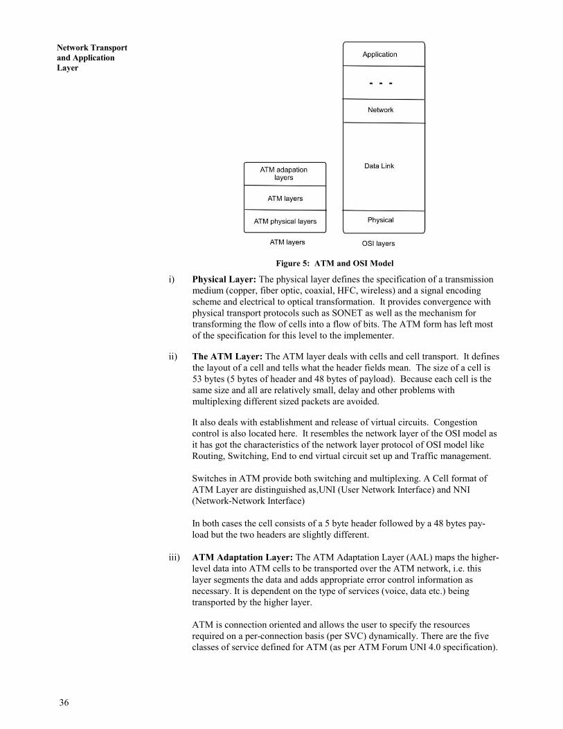
36
Concepts of
Communication and
Networking
Network Transport
and Application
Layer
Figure 5: ATM and OSI Model
i) Physical Layer: The physical layer defines the specification of a transmission
medium (copper, fiber optic, coaxial, HFC, wireless) and a signal encoding
scheme and electrical to optical transformation. It provides convergence with
physical transport protocols such as SONET as well as the mechanism for
transforming the flow of cells into a flow of bits. The ATM form has left most
of the specification for this level to the implementer.
ii) The ATM Layer: The ATM layer deals with cells and cell transport. It defines
the layout of a cell and tells what the header fields mean. The size of a cell is
53 bytes (5 bytes of header and 48 bytes of payload). Because each cell is the
same size and all are relatively small, delay and other problems with
multiplexing different sized packets are avoided.
It also deals with establishment and release of virtual circuits. Congestion
control is also located here. It resembles the network layer of the OSI model as
it has got the characteristics of the network layer protocol of OSI model like
Routing, Switching, End to end virtual circuit set up and Traffic management.
Switches in ATM provide both switching and multiplexing. A Cell format of
ATM Layer are distinguished as,UNI (User Network Interface) and NNI
(Network-Network Interface)
In both cases the cell consists of a 5 byte header followed by a 48 bytes pay-
load but the two headers are slightly different.
iii) ATM Adaptation Layer: The ATM Adaptation Layer (AAL) maps the higher-
level data into ATM cells to be transported over the ATM network, i.e. this
layer segments the data and adds appropriate error control information as
necessary. It is dependent on the type of services (voice, data etc.) being
transported by the higher layer.
ATM is connection oriented and allows the user to specify the resources
required on a per-connection basis (per SVC) dynamically. There are the five
classes of service defined for ATM (as per ATM Forum UNI 4.0 specification).

37
Introduction to Network
Architectures ATM Service Classes
Service Class
Quality of Service Parameter
Constant bit rate
(CBR)
CBR class is used for emulating circuit switching. The
cell rate is constant with time. CBR applications are
sensitive to cell-delay variation. Examples of
applications that can use CBR are telephone traffic (i.e.
nx64 kbps), video conferencing and television.
Variable bit rate–non-
real time (VBR–NRT)
VBR-NRT class allows users to send traffic at a rate that
varies with time depending on the availability of user
information. Statistical multiplexing is provided to make
optimum use of network resources. Multimedia e-mail is
an example of VBR–NRT.
Variable bit rate–real
time (VBR–RT)
This class is similar to VBR–NRT but is designed for
applications that are sensitive to cell-delay variation.
Examples for real-time VBR are voice with speech
activity detection (SAD) and interactive compressed
video.
Available bit rate
(ABR)
ABR class provides rate-based flow control and is aimed
at data traffic such as file transfer and e-mail. Although
the standard does not require the cell transfer delay and
cell-loss ratio to be guaranteed or minimized, it is
desirable for switches to minimize delay and loss as
much as possible. Depending upon the state of
congestion in the network, the source is required to
control its rate. The users are allowed to declare a
minimum cell rate, which is guaranteed to the
connection by the network.
Unspecified bit rate
(UBR)
UBR class is widely used today for TCP/IP.
The ATM Forum has identified certain technical parameters to be associated with a
connection.
Depending on the type of data, several types of AAL layers have been defined.
However, no AAL is restricted to a specific data class or type; all types of data could
conceivably be handled by any of the AALs. The various AAL protocols defined are:
1. AAL 1
2. AAL 2
3. AAL 3/4 (layer 3 and 4 were merged to avoid function overlapping)
4. AAL 5

38
Concepts of
Communication and
Networking
Network Transport
and Application
Layer
Each layer of ATM is further divided into two sublayers
• SAR (Segmentation and Reassembly)
• CS (Convergence Sublayer).
Segmentation & Reassembly: This is the lower part of the AAL. The SAR
sublayer breaks packets up into cells on the transmission side and puts them
back together again at the destination. It can add headers and trailers to the data
units given to it by the CS to form payloads. It is basically concerned with
cells.
Convergence Sublayer: The CS sublayer makes it possible to have ATM
systems offer different kind of services to different applications. The CS is
responsible for accepting bit streams or arbitrary length messages from the
application and breaking them into units of 44 or 48 bytes for transmission.
Working of ATM
When a user sends data over the ATM network, the higher-level data unit is passed
down to the Convergence Sublayer of the AAL Layer, which prepares the data for the
ATM Layer according to the designated AAL protocol. The data is then passed down to
the Segmentation and Reassembly Sublayer of the AAL Layer, which divides the data
unit into appropriately sized segments.
These segments are then passed down to the ATM Layer, which defines an
appropriate cell header for each segment and encapsulates the header and payload
segment into a 53-byte ATM cell. The cells are then passed down to the Physical
Layer, which streams the cells at an appropriate pace for the transmission medium
being used, adding empty cells as needed.
ATM circuit connections are of two types:
1. Virtual Paths and
2. Virtual Channels.
A virtual channel is a unidirectional pipe made up from the concatenation of a
sequence of connection elements. A virtual path consists of a set of these virtual
channels. Each virtual channel and virtual path has an identifier associated with it.
Virtual path is identified by Virtual Path Identifiers (VPI) and a virtual channel is
identified by a Virtual Channel Identifier (VCI). All channels within a single path
must have distinct channel identifiers but may have the same channel identifier as
channels in different virtual paths.
An individual channel can therefore be uniquely identified by its virtual channel and
virtual path number. Cell sequence is maintained through a virtual channel
connection.
ATM connections can be categorised into two types:
i) Point-to-point connections: These are the connections which connect two
ATM end-systems. Such connections can be unidirectional or bidirectional.
ii) Point-to-multipoint connections: These are the connections which connects a
single source end-system known as the root node) to multiple destination end-
systems (known as leaves).
The basic operation of an ATM switch is very simple to understand.
1. The ATM switch receives a cell across a link on a known VCI or VPI value.
39
Introduction to Network
Architectures 2. The ATM switch looks up the connection value in a local translation table to
determine the outgoing port (or ports) of the connection and the new VPI/VCI
value of the connection on that link.
3. The ATM switch then retransmits the cell on that outgoing link with the
appropriate connection identifiers.
The manner in which the local translation tables are set up determine the two
fundamental types of ATM connections:
• Permanent Virtual Connections (PVC): A PVC is a connection set up by some
external mechanism, typically network management, in which a set of switches
between an ATM source and destination ATM system are programmed with the
appropriate VPI/VCI values.
• Switched Virtual Connections (SVC): An SVC is a connection that is set up
automatically through a signalling protocol. SVCs do not require the manual
interaction needed to set up PVCs and as such, are likely to be much more
widely used.
Traffic Control
An ATM network needs efficient Traffic Control mechanisms to allocate network
resources in such a way as to separate traffic flows according to the various service
classes and to cope with potential errors within the network at any time.
Network Resource Management: Network Resource management deals with
allocation of network resources in such a way that traffic is separated on the basis of
the service characteristics. A tool of network resource management which can be
used for Traffic Control is the virtual path technique. A virtual path connection
(VPC) groups several virtual channel connections (VCC)s together such that only the
collective traffic of an entire virtual path has to be handled. In this type of setup,
priority control can be supported by reaggregating traffic types requiring different
qualities of service through virtual paths. Messages for the operation of traffic control
can be more easily distributed, a single message referring to all the virtual channels
within a virtual path will do.
Connection Admission Control: Connection Admission Control is the set of actions
taken by the network in protecting itself from excessive input loads. When a user
requests a new virtual path connection or virtual channel connection, the user needs to
specify the traffic characteristics in both directions for that connection. The network
establishes such a connection only if sufficient network resources are available to
establish the end-to-end connection with the required quality of service. The agreed
quality of service for any of the existing channels must not be affected by the new
connection.
Usage Parameter Control and Network Parameter Control: After a connection is
accepted by the Connection Admission Control function, the UPC function of
network monitors the connection to check whether the traffic conforms to the traffic
contract.
The main purpose of UPC/NPC is to protect the network resources from an overload
on one connection that would affect the quality of service of other already established
connections. Usage Parameter Control (UPC) and Network Parameter Control (NPC)
do the same job at different interfaces. The UPC function is performed at the UNI,
while the NPC function is performed at the NNI.
Functions performed by the Usage parameter control include:
• Checking the validity of VPI/VCI values.
40
Concepts of
Communication and
Networking
Network Transport
and Application
Layer
• Monitoring the traffic volume entering the network from all active VP and VC
connections to ensure that the agreed parameters are not violated.
• Monitoring the total volume of the accepted traffic on the access link.
• Detecting violations of contracted (agreed) parameter values and taking
appropriate actions.
Priority Control: Priority control is an important function as its main objective is to
discard lower priority cells in order to protect the performance of higher-priority cells.
Congestion Control: Congestion is a state of network wherein the network resources
are overloaded. This situation indicates that the network is not able to guarantee the
negotiated quality of service to the established connections and to the new connection
requests. ATM Congestion control refers to the measures taken by the network to
minimize the intensity, spread and duration of network congestion.
1. As a high-bandwidth medium with low delay and the capability to be switched or
routed to a specific destination, ATM provides a uniformity that meets the needs
of the telephone, cable television, video and data industries. This universal
compatibility makes it possible to interconnect the networks — something that is
not currently possible because of the various transmission standards used by each
industry.
2. One of the key advantages of ATM is its ability to transmit video without creating
a jittery picture or losing the synchronisation of the sound and picture. This is
possible due to proper resource allocation and admission control.
3. ATM also provides dynamic bandwidth for bursty traffic.
4. Telephone networks connect each telephone to every other telephone using a
dedicated path, but carry narrow bandwidth signals. Cable networks carry
broadband signals, but only connect subscribers to centralised locations. To build
a network that would provide a dedicated connection between sender and receiver
for broadband communications would be prohibitively expensive. For this reason,
ATM seems to be the best hope since it can use existing networks to deliver
simple voice and data as well as complex and time-sensitive television signals.
ATM can also handle bi-directional communications easily.
5. Unlike packet switching, ATM is designed for high-performance multimedia
networking.
���� Check Your Progress 2
1. What are VPI and VCI in ATM network? Write the importance of each.
……………………………………………………………………………………
……………………………………………………………………………………
……………………………………………………………………………………
……………………………………………………………………………………
2. Explain how ATM layers are divided into sub-layers.
……………………………………………………………………………………
……………………………………………………………………………………
……………………………………………………………………………………
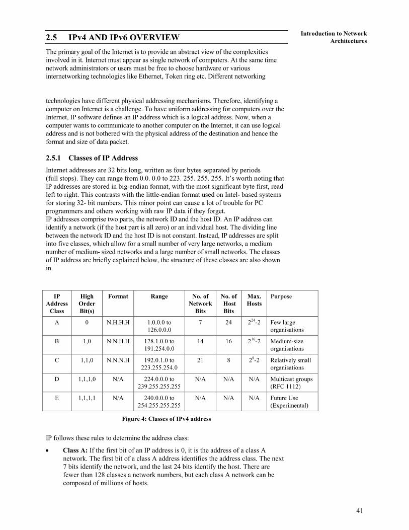
41
Introduction to Network
Architectures 2.5 IPv4 AND IPv6 OVERVIEW
The primary goal of the Internet is to provide an abstract view of the complexities
involved in it. Internet must appear as single network of computers. At the same time
network administrators or users must be free to choose hardware or various
internetworking technologies like Ethernet, Token ring etc. Different networking
technologies have different physical addressing mechanisms. Therefore, identifying a
computer on Internet is a challenge. To have uniform addressing for computers over the
Internet, IP software defines an IP address which is a logical address. Now, when a
computer wants to communicate to another computer on the Internet, it can use logical
address and is not bothered with the physical address of the destination and hence the
format and size of data packet.
2.5.1 Classes of IP Address
Internet addresses are 32 bits long, written as four bytes separated by periods
(full stops). They can range from 0.0. 0.0 to 223. 255. 255. 255. It’s worth noting that
IP addresses are stored in big-endian format, with the most significant byte first, read
left to right. This contrasts with the little-endian format used on Intel- based systems
for storing 32- bit numbers. This minor point can cause a lot of trouble for PC
programmers and others working with raw IP data if they forget.
IP addresses comprise two parts, the network ID and the host ID. An IP address can
identify a network (if the host part is all zero) or an individual host. The dividing line
between the network ID and the host ID is not constant. Instead, IP addresses are split
into five classes, which allow for a small number of very large networks, a medium
number of medium- sized networks and a large number of small networks. The classes
of IP address are briefly explained below, the structure of these classes are also shown
in.
Figure 4: Classes of IPv4 address
IP follows these rules to determine the address class:
• Class A: If the first bit of an IP address is 0, it is the address of a class A
network. The first bit of a class A address identifies the address class. The next
7 bits identify the network, and the last 24 bits identify the host. There are
fewer than 128 classes a network numbers, but each class A network can be
composed of millions of hosts.
IP
Address
Class
High
Order
Bit(s)
Format Range No. of
Network
Bits
No. of
Host
Bits
Max.
Hosts
Purpose
A 0 N.H.H.H 1.0.0.0 to
126.0.0.0
7 24 224
-2 Few large
organisations
B 1,0 N.N.H.H 128.1.0.0 to
191.254.0.0
14 16 216
-2 Medium-size
organisations
C 1,1,0 N.N.N.H 192.0.1.0 to
223.255.254.0
21 8 28-2 Relatively small
organisations
D 1,1,1,0 N/A 224.0.0.0 to
239.255.255.255
N/A N/A N/A Multicast groups
(RFC 1112)
E 1,1,1,1 N/A 240.0.0.0 to
254.255.255.255
N/A N/A N/A Future Use
(Experimental)
42
Concepts of
Communication and
Networking
Network Transport
and Application
Layer
• Class B: If the first 2 bits of the address are 1 0, it is a class B network address.
The first 2 bits identify class; the next 14 bits identify the network, and the last
16 bits identify the host. There are thousands of class B network numbers and
each class B network can contain thousands of hosts.
• Class C: If the first 3 bits of the address are 1 1 0, it is a class C network
address. In a class C address, the first 3 bits are class identifiers; the next 21 bits
are the network address, and the last 8 bits identify the host. There are millions
of class C network numbers, but each class C network is composed of fewer
than 254 hosts.
• Class D: If the first 4 bits of the address are 1 1 1 0, it is a multicast address.
These addresses are sometimes called class D addresses, but they don’t really
refer to specific networks. Multicast addresses are used to address groups of
computers all at one time. Multicast addresses identify a group of computers
that share a common application, such as a video conference, as opposed to a
group of computers that share a common network.
• Class E: If the first four bits of the address are 1 1 1 1, it is a special reserved
address. These addresses are called class E addresses, but they don’t really refer
to specific networks. No numbers are currently assigned in this range.
IP addresses are usually written as four decimal numbers separated by dots (periods).
Each of the four numbers is in the range 0-255 (the decimal values possible for a single
byte). Because the bits that identify class are contiguous with the network bits of the
address, we can lump them together and look at the address as composed of full bytes of
network address and full bytes of host address. If the value of the first byte is:
• Less than 128, the address is class A; the first byte is the network number, and
the next three bytes are the host address.
• From 128 to 191, the address is class B; the first two bytes identify the network,
and the last two bytes identify the host.
• From 192 to 223, the address is class C; the first three bytes are the network
address, and the last byte is the host number.
• From 224 to 239, the address is multicast. There is no network part. The entire
address identifies a specific multicast group.
• Greater than 239, the address is reserved.
To learn further about IP address and CIDR you can see the course material of BCS-
061: TCP/IP programme which you will study in your next semester.
IPv6 Overview
With the advancement in the technologies, mobile-handheld devices and emerging
applications, it is quite evident that soon the IP addresses provided by IPv4 are not
sufficient. In the recent future we can operate and use various smart deices (like TV,
Fridges, cameras, ACs, phone, mobiles, etc). Each of such devices will require a unique
IP address, which will increase the demand of IP addresses exponentially.
The number of IPv4 unique addresses is not that large in relation to the current rate of
expansion of the Internet. Consequently, a new addressing system has been devised
which is a part of Internet Protocol version 6 (IPv6), which uses 128-bit addresses,
means total addresses will be 2128 .. IPv4 uses 32-bit addresses, means total addresses
will be 232
around 4,294,967,296 unique addresses. IPv6 has almost 7.9x1028
times more
addresses than IPv4.
It is possible that IPv6 would not be used or implemented completely in the coming
couple of years. This IPv6 (Internet Protocol version 6) is a revision of the earlier
43
Introduction to Network
Architectures Internet Protocol (IP) version 4. As you know IPv4 address is 32 bit and divided into
four octets separated by dot for example 192.186.12.10, on the other hand IPv6
addresses are consist of eight groups of four hexadecimal digits separated by colons, for
example 2001:0db8:85a3:0042:0000:8a2e:0370:7334. IPv6 is designed to swap the
existing IPv4, which is the main communications protocol for most Internet traffic as of
today. IPv6 was developed to deal with the long-anticipated problem of IPv4 running out
of addresses, some of the reasons and need for implementing IPv6 are following:
• The short term solutions like sub-netting, classless addressing cannot fulfill the
massive future demand of address space.
• The internet must accommodate the real-time audio and video transmission with
best quality of services.
• Internet protocol must provide the necessary security implementation for some
applications.
• There is a need of multicasting in current IPv4, where the transmission of a packet
to multiple destinations can be sent in a single send operation.
• IPv4 need a major revision in various issues like privacy, mobility, routing, QoS
(quality of services), extendibility and addressing.
Address format
As we discussed before, IPv6 addresses are consist of eight groups of four
hexadecimal digits separated by colons (:), for example
2001:0db8:85a3:0042:0000:8a2e:0370:7334. Lets see the bit composition of an IPv6
address, as we know each hexadecimal should be of 4 bits each, in a group we have
four hexadecimal bits hence a group has 16 bits. Now we have 8 groups so 16
multiple with 8 is 128 bits. Any IPv6 address may be reduced and interpreted using
the following rules:
• First thing is leading zeroes from the groups of hexadecimal digits can be
removed, similar to the currency where leading zeros are nothing. For example,
convert the group 0036 to 36.
• Always remember that hexadecimal digits in the groups are not case-sensitive just
like the c programming; e.g., the groups 08DB and 08db are same.
• Next you may merge successive groups of one or more zeroes, using a double
colon (::) to indicate the omitted groups. But, double colon may only be used
once in any given address
The initial process and few implementation of IPv6 have been done, but still the
transition process of replacing from IPv4 with IPv6 will continue for couple of years.
We must consider that at present IPv4 is backbone of Internet, replacing it, is not an
easy process. Definitely it will be done slow transition from one stage to another.
Following are the approaches being used for replacing from IPv4 with IPv6:
1. Protocol Translation
2. Dual IP Stack
3. Tunneling
Protocol Translation
Like any other protocol both IPv4 and IPv6 are using their own headers. There are
different kinds of IPv4 to IPv6 translators possible
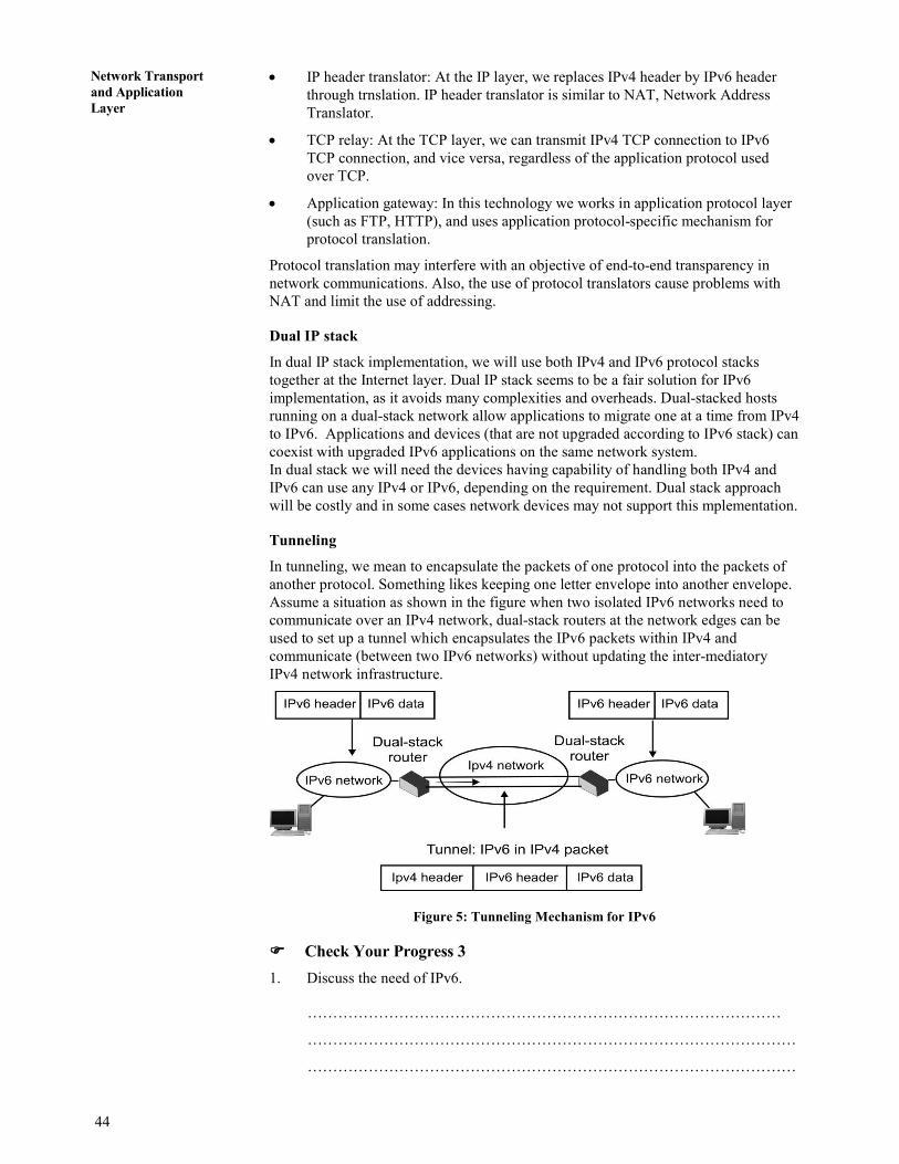
44
Concepts of
Communication and
Networking
Network Transport
and Application
Layer
• IP header translator: At the IP layer, we replaces IPv4 header by IPv6 header
through trnslation. IP header translator is similar to NAT, Network Address
Translator.
• TCP relay: At the TCP layer, we can transmit IPv4 TCP connection to IPv6
TCP connection, and vice versa, regardless of the application protocol used
over TCP.
• Application gateway: In this technology we works in application protocol layer
(such as FTP, HTTP), and uses application protocol-specific mechanism for
protocol translation.
Protocol translation may interfere with an objective of end-to-end transparency in
network communications. Also, the use of protocol translators cause problems with
NAT and limit the use of addressing.
Dual IP stack
In dual IP stack implementation, we will use both IPv4 and IPv6 protocol stacks
together at the Internet layer. Dual IP stack seems to be a fair solution for IPv6
implementation, as it avoids many complexities and overheads. Dual-stacked hosts
running on a dual-stack network allow applications to migrate one at a time from IPv4
to IPv6. Applications and devices (that are not upgraded according to IPv6 stack) can
coexist with upgraded IPv6 applications on the same network system.
In dual stack we will need the devices having capability of handling both IPv4 and
IPv6 can use any IPv4 or IPv6, depending on the requirement. Dual stack approach
will be costly and in some cases network devices may not support this mplementation.
Tunneling
In tunneling, we mean to encapsulate the packets of one protocol into the packets of
another protocol. Something likes keeping one letter envelope into another envelope.
Assume a situation as shown in the figure when two isolated IPv6 networks need to
communicate over an IPv4 network, dual-stack routers at the network edges can be
used to set up a tunnel which encapsulates the IPv6 packets within IPv4 and
communicate (between two IPv6 networks) without updating the inter-mediatory
IPv4 network infrastructure.
Figure 5: Tunneling Mechanism for IPv6
���� Check Your Progress 3
1. Discuss the need of IPv6.
…………………………………………………………………………………
……………………………………………………………………………………
……………………………………………………………………………………
45
Introduction to Network
Architectures 2. Explain the dual stack approach for IPv6 implementation.
……………………………………………………………………………………
……………………………………………………………………………………
……………………………………………………………………………………
……………………………………………………………………………………
1.5 SUMMARY
Network architecture is a complete design of a communications network. Primarily
we can say that it is a framework for the specification of a network's physical
components, their functional organization and configuration. In this unit you have
learnt about X.25, Frame Relay and ATM Architectures. X.25 is an old standard
protocol suite for packet based wide area network. The old networks mainly tele-
communications companies and ATM’s (automated teller machines) were following
X.25 protocols for packet switching based network. Frame Relay is a virtual-circuit
based WAN that was designed to provide more efficient transmission scheme than
X.25. It provides connection oriented services at reasonable speed and low cost.
Asynchronous Transfer Mode (ATM) is a form of data transmission that allows voice,
video and data to be sent along the same network. In contrast to ATM, in the past,
voice, video and data were transferred using separate networks. In this unit you have
also studied about ISP and different address schemes of TCP/IP protocols suits. Now
you know that the number of IPv4 unique addresses is not that large in relation to the
current rate of expansion of the Internet. Consequently, a new addressing system has
been devised which is a part of Internet Protocol version 6 (IPv6), which uses 128-bit
addresses, means total addresses will be 2128 .
. In this unit you have also learnt about
different approaches, which can be used for replacing from IPv4 with IPv6.
1.6 SOLUTIONS/ANSWERS
���� Check Your Progress 1
1. Datagram allows for dynamic handling of congestion and no call setup is
necessary. Virtual circuits allow for sequencing, error and flow control.
2. X.25 is connection oriented architecture and support switched virtual circuits
(SVC) and permanent virtual circuits (PVC). Switched virtual circuits are
established on the need basis. SVC is established when a call is made and
broken down after the call is completed. On the other hand, permanent virtual
circuits are almost leased kind of connections, which provide a dedicated
connection between DTE’s.
3. Following are the differences between X.25 and Frame Relay:
• Frame Relay operates a higher speed
• Frame relay operate in only physical and data link layer. (so it can easily
be used as backbone network to other protocols have network layer with
less overheads)
• Frame Relay allows bursty data. It means if at some point large amount of
data is sent by someone than network should able to handle it properly.
• Frame relay allow a Frame size of 9000 bytes, which can accommodates
all LAN Frame sizes.
• It is less expensive than X.25.

46
Concepts of
Communication and
Networking
Network Transport
and Application
Layer
• It has error detection at data link layer only.
4. FECN and BECN are used in Frame Relay mainly for congestion control
FECN (Forward Explicit Congestion Notification): FECN bit can be set
(“1”) by any switch of the network to indicate that traffic is congested in the
frames travelling towards the destination machine. This bit informs the
destination that congestion has occurred, so destination should is ready for
delay or packet loss.
BECN (Backward Explicit Congestion Notification): BECN bit also indicate
congestion in a Network. BECN bit can be set (“1”) by any switch of the
network to indicate that traffic is congested in the frames travelling towards the
source machine. This bit informs the sender machine that congestion had
occurred in the network, hence slow-down the processing to prevent further
delay or packet loss.
���� Check Your Progress 2
1. Virtual Path Identifier (VPI) is an 8-bit field for the UNI and a 12-bit field for
the NNI. It constitutes a routing field for the network and is used to identify
virtual paths. In an idle cell, the VPI is set to all 0’s. Together with the Virtual
Channel Identifier, the VPI provides a unique local identification for the
transmission.
Virtual Channel Identifier (VCI) is a 16-bit field used to identify a virtual
channel. For idle cells, the VCI is set to all 0’s. It functions as a service access
point and it is used for routing to and from the end user. Together with the
Virtual Path Identifier, the VCI provides a unique local identification for
the transmission.
2. Each layer of ATM is further divided into two sublayers SAR (Segmentation
and Reassembly) and CS (Convergence Sublayer).
Segmentation & Reassembly: This is the lower part of the AAL. The SAR
sublayer breaks packets up into cells on the transmission side and puts them
back together again at the destination. It can add headers and trailers to the data
units given to it by the CS to form payloads. It is basically concerned with
cells.
Convergence Sublayer: The CS sublayer makes it possible to have ATM
systems offer different kind of services to different applications. The CS is
responsible for accepting bit streams or arbitrary length messages from the
application and breaking them into units of 44 or 48 bytes for transmission.
���� Check Your Progress 3
1. With the advancement in the technologies, mobile-handheld devices and emerging
applications, it is quite evident that soon the IP addresses provided by IPv4 are
not sufficient. In the recent future we can operate and use various smart deices
(like TV, Fridges, cameras, ACs, phone, mobiles, etc). Each of such devices will
require a unique IP address, which will increase the demand of IP addresses
exponentially.
The number of IPv4 unique addresses is not that large in relation to the current
rate of expansion of the Internet. Consequently, a new addressing system has
been devised which is a part of Internet Protocol version 6 (IPv6), which uses
128-bit addresses, means total addresses will be 2128 .
. IPv4 uses 32-bit
47
Introduction to Network
Architectures addresses, means total addresses will be 2
32 around 4,294,967,296 unique
addresses. IPv6 has almost 7.9x1028 times more addresses than IPv4.
2. In dual IP stack implementation, we will use both IPv4 and IPv6 protocol stacks
together at the Internet layer. Dual IP stack seems to be a fair solution for IPv6
implementation, as it avoids many complexities and overheads. Dual-stacked
hosts running on a dual-stack network allow applications to migrate one at a time
from IPv4 to IPv6. Applications and devices (that are not upgraded according to
IPv6 stack) can coexist with upgraded IPv6 applications on the same network
system.
In dual stack we will need the devices having capability of handling both IPv4
and IPv6 can use any IPv4 or IPv6, depending on the requirement. Dual stack
approach will be costly and in some cases network devices may not support this
implementation.

48
Concepts of
Communication and
Networking
Network Transport
and Application
Layer
UNIT 3 INTRODUCTION TO WIRELESS
AND MOBILE NETWORKS
Structure Page Nos.
3.0 Introduction Systems 48
3.0.1 Wired Communication System
3.0.2 Wireless Communication System
3.1 Objectives 50
3.2 Wireless Communication Systems 51
3.2.1 Paging System
3.2.2 Cordless Telephone System
3.2.3 Cellular Mobile System
3.2.4 Bluetooth
3.2.5 Wireless Local Area Network (WLAN)
3.3 Wireless Generations 54
3.3.1 First Generation (1G) –
3.3.2 Second Generation (2G) –
3.3.3 Evolution To Mid of Second Generation (2.5G) –
3.3.4 Third Generation (3G) –
3.4 Introduction to Cellular Mobile Systems – GSM 56
3.5 Code Division Multiple Access (CDMA) 59
3.6 Cellular System Design Fundamental 60
3.6.1 Frequency Reuse
3.6.2 Hand-Off and Signal Strength
3.6.3 Interference
3.6.4 Coverage and Capacity Improvements
3.7 Summary 64
3.8 Suggested Reading 64
3.9 Solutions / Answers 65
3.0 INTRODUCTION SYSTEMS
Communication Systems enables two or more person to communicate each other
irrespective of their geographic location distance. This is only because of
communication technology which provide such seamless service to their customers.
Therefore, this communication service has tremendously grown among people in the
past few years as it has eliminated the obstacle caused by geographic distance
between people. Now there are modes of this communication system through which
this service can be provided. The first one is the wired communication system and the
other one is wireless communication system. Please note that in this chapter, the terms
“wireless” and “cellular” are used interchangeably. Both are used in view of mobility.
Moreover, in all diagrams, a dotted line represents a wireless link whereas a solid line
represents a wired communication link.
3.1.1 Wired Communication System
The Wired Communication System depends solely on wires as e all the users (or
communicators) are connected to each other through wires. The typical example
(Figure 1) of such wired communication system can be a Local Area Network (LAN)
where people are communicating and linked with each other through wires. Wire can
be a cable wire, optical wire or any other type of wire.
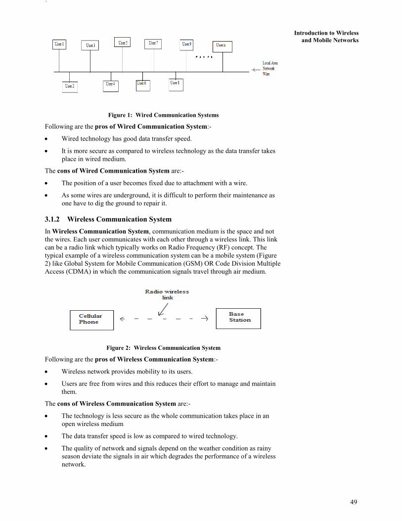
`
49
Introduction to Wireless
and Mobile Networks
Figure 1: Wired Communication Systems
Following are the pros of Wired Communication System:-
• Wired technology has good data transfer speed.
• It is more secure as compared to wireless technology as the data transfer takes
place in wired medium.
The cons of Wired Communication System are:-
• The position of a user becomes fixed due to attachment with a wire.
• As some wires are underground, it is difficult to perform their maintenance as
one have to dig the ground to repair it.
3.1.2 Wireless Communication System
In Wireless Communication System, communication medium is the space and not
the wires. Each user communicates with each other through a wireless link. This link
can be a radio link which typically works on Radio Frequency (RF) concept. The
typical example of a wireless communication system can be a mobile system (Figure
2) like Global System for Mobile Communication (GSM) OR Code Division Multiple
Access (CDMA) in which the communication signals travel through air medium.
Figure 2: Wireless Communication System
Following are the pros of Wireless Communication System:-
• Wireless network provides mobility to its users.
• Users are free from wires and this reduces their effort to manage and maintain
them.
The cons of Wireless Communication System are:-
• The technology is less secure as the whole communication takes place in an
open wireless medium
• The data transfer speed is low as compared to wired technology.
• The quality of network and signals depend on the weather condition as rainy
season deviate the signals in air which degrades the performance of a wireless
network.

50
Concepts of
Communication and
Networking
Network Transport
and Application
Layer
Modes of Wireless Communication System in small distance
Despite of cons of wireless network, this technology usage is increasing day by day
and reaching to every people due to its advantage of getting people free form wires
and providing them mobility. Therefore, our focus we will be on Wireless
Technology. Now, we will discuss the two modes in which a wireless technology
works.
• Access Point (AP) Wireless Communication System :-
The first mode is called Access Point (AP) Wireless Communication System.
In this Access Point (AP) wireless communication system (Figure 3), the data
transfer takes place from source (User 1) to destination (User 2) through an
Access Point. This access point can be a modem or a switch etc. This access
point decides the path for data transfer to follow, data transfer speed, calculates
the shortest path etc from source (User 1) to destination (User 2). No two users
or more users can communicate directly or without an access point in this mode.
The example of Access Point (AP) wireless technology is a wireless LAN
network where r a modem decides the path and transfers the data form User 1 to
User 2.
Figure 3: Access Point (AP) Wreless Communication System
• Ad-hoc wireless Communication System :-
The second mode is Ad-hoc wireless communication system mode. In this mode
(Figure 4), the data transfer takes place directly from source (User 1) to
destination (User 2). There is no need of access point in this type of mode.
Every user in this network mode communicates directly with each other. Such
types of network are temporary and its establishment is very quick as compared
to access point mode. These networks are successful where there is a
requirement of temporary network only for few days.
Figure 4: Ad-hoc Wireless Communication System
3.1 OBJECTIVES
After going through this unit you will be able to:
• define the wired and wireless communication systems;
• discuss the various wireless communication systems;
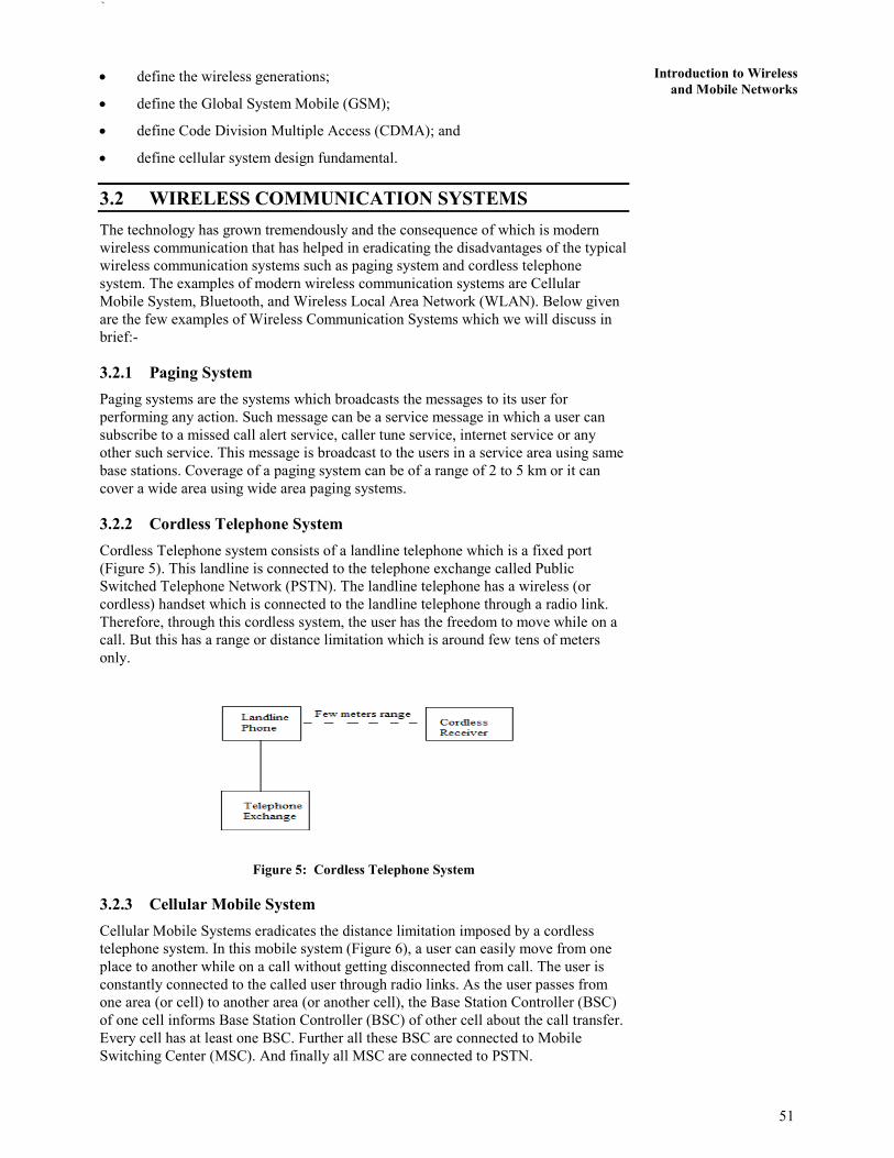
`
51
Introduction to Wireless
and Mobile Networks• define the wireless generations;
• define the Global System Mobile (GSM);
• define Code Division Multiple Access (CDMA); and
• define cellular system design fundamental.
3.2 WIRELESS COMMUNICATION SYSTEMS
The technology has grown tremendously and the consequence of which is modern
wireless communication that has helped in eradicating the disadvantages of the typical
wireless communication systems such as paging system and cordless telephone
system. The examples of modern wireless communication systems are Cellular
Mobile System, Bluetooth, and Wireless Local Area Network (WLAN). Below given
are the few examples of Wireless Communication Systems which we will discuss in
brief:-
3.2.1 Paging System
Paging systems are the systems which broadcasts the messages to its user for
performing any action. Such message can be a service message in which a user can
subscribe to a missed call alert service, caller tune service, internet service or any
other such service. This message is broadcast to the users in a service area using same
base stations. Coverage of a paging system can be of a range of 2 to 5 km or it can
cover a wide area using wide area paging systems.
3.2.2 Cordless Telephone System
Cordless Telephone system consists of a landline telephone which is a fixed port
(Figure 5). This landline is connected to the telephone exchange called Public
Switched Telephone Network (PSTN). The landline telephone has a wireless (or
cordless) handset which is connected to the landline telephone through a radio link.
Therefore, through this cordless system, the user has the freedom to move while on a
call. But this has a range or distance limitation which is around few tens of meters
only.
Figure 5: Cordless Telephone System
3.2.3 Cellular Mobile System
Cellular Mobile Systems eradicates the distance limitation imposed by a cordless
telephone system. In this mobile system (Figure 6), a user can easily move from one
place to another while on a call without getting disconnected from call. The user is
constantly connected to the called user through radio links. As the user passes from
one area (or cell) to another area (or another cell), the Base Station Controller (BSC)
of one cell informs Base Station Controller (BSC) of other cell about the call transfer.
Every cell has at least one BSC. Further all these BSC are connected to Mobile
Switching Center (MSC). And finally all MSC are connected to PSTN.

52
Concepts of
Communication and
Networking
Network Transport
and Application
Layer
Figure 6: Cellular Mobile System
3.2.4 Bluetooth
As discussed above, Bluetooth works on ad-hoc mode in which the network is formed
quickly and is of temporary basis. Bluetooth technology is created by a telecom
company called Ericsson in 1994. It was developed in order to connect two devices
without wires. The range in which Bluetooth technology works is of 10 meters (or 30
feet approx) only. The name “Bluetooth” is after tenth-century king Harald I of
Denmark and parts of Norway who united Danish tribes into a single kingdom. The
implication is that Bluetooth does the same with communications protocols, uniting
them into one universal standard.
Bluetooth works on 2.4 GHz ISM band (Industrial, Scientific and Medical band)
which divides the data into parts and sends it on up to 79 bands. It uses Frequency
Hopping Spread Spectrum (FHSS) with Time Division Duplexing (TDD) technique at
the rate of 1600 hops/sec. Moreover, the modulation technique employed is Guassian
Frequency Shift Keying (GFSK) which was the only available modulation technique
at the time of Bluetooth. Data rate is around 128 Mbps (Mega Bits per Second) and
can support up to 8 devices simultaneously in Master-Slave mode. Bluetooth has
versions started from version 1.0 to version 4.0.
3.2.5 Wireless Local Area Network (WLAN)
WLAN is a local area network but the end point at which the user gets the service is a
wireless end. As you can see in below Figure 7, the user is connected to Access Point
through a wireless link. The Access point is further connected to a LAN line which is
wired. Therefore, in WLAN, only the last end is wireless and rest is wired network.
Figure 7: Wireless Local Area Network
WALN technology works on IEEE 802.11 standard. Components of 802.11 are Basic
Service Set (BSS), Extended Service Set (ESS), Access Point (AP) and Distribution
Systems (DS). We will now discuss these components in brief.
Basic Service Set (BSS) – BSS contains one or more mobile user (Figure 8 & 9). BSS
can work in two modes. One is independent mode in which all users are connected to
each other directly. The other mode is infrastructure mode in which all users
communicate through an Access Point (AP).
Access Point – An AP can be a modem, router or a switch through which users
communicate with each other. When a network employs this component, that network
is called infrastructure mode. All the data passes through this AP.

`
53
Introduction to Wireless
and Mobile Networks
Figure 8: BSS Without Acess Point (AP) Figure 9: BSS With Acess Point(AP)
Extended Service Set (ESS) - All separate BSS (either in independent mode or in
infrastructure mode) when connected to each other is called an Extended Service Set
(Figure 10).
Distribution System (DS) – Distribution system connects AP of different ESS. This
increases network coverage as all the users of different BSS will be connected with
each other through DS (Figure 10). All the links connecting APs to DS can be
wireless or wired.
Figure 10: Extended Service Set (ESS) and Distribution Systems(DS)
���� Check Your Progress 1
1. State True or False
a) Wired communication systems are less secure than wireless
communication system.
b) Wireless communication systems are easy to set up.
c) Data transfer speed is less in wireless communication system.
d) Ad-hoc wireless communication system uses an access point for users
to get connected to each other.
e) In Wireless Local Area Network (WLAN), each point is a wireless point.
f) Basic Service Set (BSS) provides the ability for all Access Point (APs) to
get connected to each other.
2. Discuss about Bluetooth Technology?
…………………………………………………………………………………….
…………………………………………………………………………………….
…………………………………………………………………………………….
…………………………………………………………………………………….

54
Concepts of
Communication and
Networking
Network Transport
and Application
Layer
3. Explain how Cordless Telephone System works?
…………………………………………………………………………………….
…………………………………………………………………………………….
…………………………………………………………………………………….
3.3 WIRELESS GENERATIONS
Cellular Mobile System has come a long way as at present scenario, every person
carries a cellular phone in his/her hand. This tremendous growth has established the
growth of cellular technology. From a cordless phone which gave mobility to users
but only of short distance in meters to a basic phone which has overcome the
disadvantage of short range cordless phone. And now today, a basic cellular phone is
converted to a smart multimedia cellular phone which is used not only for making
calls but is used to click pictures, listen songs, record voice, checking mails etc. In this
section, we will draw your attention towards the emerging generations of a wireless
cellular phone.
Before starting with generations, we will discuss the two channel access technologies
- Time Division Multiple Access (TDMA) and Frequency Division Multiple Access
(FDMA) which are used in these generations.
Frequency Division Multiple Access (FDMA) allocates individual frequency channel
to an individual user at a time. Each user gets a frequency channel whenever the user
demands for it. Any other user cannot use the same frequency channel until the
assigned channel is given back by the user to the pool of freely available frequency
channel.
Time Division Multiple Access (TDMA) divides an individual frequency channel into
number of time slots. These time slots are then allocated to users on demand. Unlike
FDMA, one or more user can share the same frequency channel. Each slot is used
either for transmitting or receiving signals. Therefore, the data transmission is non-
continuous in nature which makes the hand-off simpler. Consecutive slots are used to
transmit the data.
3.3.1 First Generation (1G) –
First Generation also called 1G is based on analog Frequency Modulation (FM) and
Frequency Division Multiple Access (FDMA). 1G uses circuit switched technology
and came in 1980. According to this generation, each user has allocated with a
dedicated frequency channel. Moreover, this generation made solely to provide voice
services to its users. It was not intended for any data services. These lacked features in
1G were the biggest reason behind the rise of Second Generation (2G).
3.3.2 Second Generation (2G) –
Second Generation provides the voice as well as data services to its users. Unlike 1G,
no user has allocated dedicated frequency channel. 2G uses digital modulation
technique and multiple access techniques like Time Division Multiple Access
(TDMA) and Code Division Multiple Access (CDMA). 2G came in 1990 and uses
circuit switched technology. Every user in 2G uses a time-sharing frequency channel.
In this generation, there are 3 TDMA standards which are – Global System Mobile
(GSM), Interim Standard 136 (IS 136) and Pacific Digital Cellular (PDC) and one
CDMA standard called 2G CDMA or Interim Standard 95 (IS 95) CDMA.
• Global System Mobile (GSM) – For every 200 KHz radio channel, there are 8
times slotted users. 2G TDMA standard GSM is used in countries like Europe,
Australia, Asia and South America. It is also used in India

`
55
Introduction to Wireless
and Mobile Networks• Interim Standard 136 (IS 136) - For every 30 KHz radio channel, there are 3
times slotted users. 2G TDMA standard IS 136 is used in countries like
Australia, North America and South America. IS 136 is also known as US
Digital Cellular (USDC) or North American Digital Cellular (NADC).
• Pacific Digital Cellular (PDC) – This is a Japanese standard and is very similar
to IS 136 with around 50 million users
• 2G CDMA or Interim Standard 95 (IS 95) CDMA – For every 1.25 MHz
channel, there are up to 64 users which are orthogonally coded. This standard is
also known as CDMAOne and is used in Australia, Korea North America,
Japan, China and South America.
3.3.3 Evolution to Mid of Second Generation (2.5G) –
After the second generation comes 2.5G and introduced in the year 2000. 2.5G is
intended for faster data rates which are required for supporting modern internet
applications. Existing 2G equipment is modified (both hardware and software) to
support 2.5G services for enhanced data rates. Enhanced rata rates are provided for
services such as web browsing, mobile commerce, e-mail services and location based
mobile services. 2.5G also supports web browsing technology like Wireless
Application Protocol (WAP).
2.5 provides three TDMA upgrades which are as follows-
• High Speed Circuit Switched Data (HSCSD) – As the name suggests, this
TDMA upgrade is a circuit switched technology and provides higher data speed
rates as compared to 2G. This technology upgrade is the first attempt to provide
better data rates for GSM. Rather than allocating a single time slot to a single
user, the higher data rates are provided to users by providing consecutive time
slots. This technology also takes care of error control coding algorithm.
• General packet Radio Service (GPRS) – Unlike HSCSD, this TDMA upgrade is
a packet based technology. GPRS supports more users as compared to HSCSD.
It uses 2G TDMA modulation format but redefines air interface for better
packet data access. It is more suitable for non real time applications like
retrieval of email, faxes and asymmetric web browsing. Installation of internet
gateway and new routers at base station is mandatory for using this technology.
• Enhanced Data rates for GSM Evolution (EDGE) – EDGE provides better data
rates than GPRS by using new digital modulation technique called 8-PSK
(Phase Shift Keying).This is implemented by upgrading hardware and software
at base station. This technology is also called as Enhanced GPRS. Nine
different air interface formats are defined by EDGE known as Multiple
modulation and Coding Schemes (MCS) with error control protection.
3.3.4 Third Generation (3G) –
3G is designed to provide higher data rates with much available wider bandwidth. It
uses packet switched technology and users uses smaller bandwidth. This generation
allows the identification of user’s location. The 3G technology provides the services
like transparent roaming, communication using Voice Over Internet Protocol (VOIP),
receives live music, interactive live web sessions, better network capacity, multi
mega-bit internet access, readily available internet access and simultaneous exchange
of voice and data packets using a single cellular mobile.
The above discussed Wireless generations are compared below in the form of a
comparison Table 1.
Table 1: Comparison between Wireless Generations – 1G, 2G, 2.5G and 3G
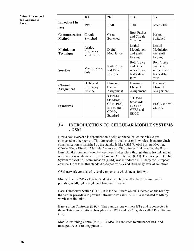
56
Concepts of
Communication and
Networking
Network Transport
and Application
Layer
1G 2G 2.5G 3G
Introduced in
year 1980 1990 2000 After 2004
Communication
Method
Circuit
Switched
Circuit
Switched
Both Packet
and Circuit
Switched
Packet
Switched
Modulation
Technique
Analog
Frequency
Modulation
Digital
Modulation
Digital
Modulation
and Shift
Keying
Digital
Modulation
and Shift
Keying
Services Voice service
only
Both Voice
and Data
services
Both Voice
and Data
services with
faster data
rates
Both Voice
and Data
services with
faster data
rates
Channel
Assignment
Dedicated
Frequency
Channel
Dynamic
Channel
Assignment
Dynamic
Channel
Assignment
Dynamic
Channel
Assignment
Standards -
3 TDMA
Standards –
GSM, PDC,
IS 136 and 1
CDMA
Standard
3 TDMA
Standards –
HSCSD,
GPRS and
EDGE
EDGE and W-
CDMA
3.4 INTRODUCTION TO CELLULAR MOBILE SYSTEMS
- GSM
Now a day, everyone is dependent on a cellular phone (called mobile) to get
connected to other person. This connectivity among users is wireless in nature. Such
communication is furnished by the standards like GSM (Global System Mobile),
CDMA (Code Division Multiple Access) etc. This wireless link is called the Radio
Link. All the communication between users takes place through this radio link and in
open wireless medium called the Common Air Interface (CAI). The concept of Global
System for Mobile Communication (GSM) was introduced in 1990 by the European
country. From then, this standard accepted widely and utilized by several countries.
GSM network consists of several components which are as follows:
Mobile Station (MS) - This is the device which is used by the GSM user and is
portable, small, light-weight and hand-held device.
Base Transceiver Station (BTS) - It is the cell tower which is located on the roof by
the service providers to provide network to its users. A BTS is connected to MS by
wireless radio links.
Base Station Controller (BSC) - This controls one or more BTS and is connected to
them. This connectivity is through wires. BTS and BSC together called Base Station
(BS).
Mobile Switching Centre (MSC) – A MSC is connected to number of BSC and
manages the call routing process.

`
57
Introduction to Wireless
and Mobile NetworksAuthentication Centre (AuC) – Authentication Centre is responsible for authenticating
a legitimate user (subscriber) and also provides 128-bit authentication key to user.
Home Location Register (HLR) – This is a database which stores the user’s
information and its location information. This provides user an IMSI (International
Mobile Subscriber Identity) number to identify its user. In other words, the area to
which a subscriber belongs is saved in HLR.
Visitor Location Register (VLR) – This database contains the information about
subscriber who visited the area of a particular MSC and stores the IMSI (Internationl
mobile subscriber indentity) number temporarily.
Operation Maintenance Centers (OMC) – The operation of each MS, BTS, BSC and
MSC is monitored and maintained by this centre.
Subscriber Identity Module (SIM) – This is a removable 16k or 32k chip (or a small
smart card) which a service provider provides to its subscriber. It is used in MS to
access the GSM services like calling, messaging etc.
Public Networks – This consists of networks like PSTN (Public Switched Telephone
Network), Data Network, ISDN (Integrated Services digital Network) to which MSC
is connected.
Below given Figure 11 is the architecture of GSM containing all the above described
components. GSM communication operates on 900 MHz/1800 MHz standards and
uses techniques like FDD (Frequency Division Duplexing) and TDMA (Time
Division Multiple Access).
Figure 11: Global System Mobile (GSM) Architecture
Several generations like 1G (First Generation), 2G (Second Generation), 3G (Third
Generation) in GSM has evolved during the past years. Even though the GSM
network is utilized by almost every country these days but this standard has some
vulnerabilities which are exploited by an intruder to get the access into the network or
disturb its operation. The radio link between the MS and BTS is the most crucial point
where an intruder takes advantage. Such vulnerabilities are listed below.
Vulnerabilities in GSM Communication
The GSM standard has some principles of security like subscriber identity
confidentiality, use of a SIM as security module, subscriber identity authentication,
use of triplets and stream ciphering of user traffic & user control data. An intruder
takes an unfair advantage between a legitimate subscriber and the wireless radio link
and breaches the security principles of GSM. This breach of principle is due to the
Following vulnerabilities present in GSM network:-

58
Concepts of
Communication and
Networking
Network Transport
and Application
Layer
• Wireless Radio Link – All the communication is taking place through the
medium of air. An intruder can easily intercept the communication between two
subscribers or between a subscriber and its connected BTS.
• Insecure A3/A5/A8 Algorithm – GSM standard uses three algorithms. A3
algorithm is used for authenticating the subscriber through a 128-bit
authentication key. A5 algorithm is used for encryption and decryption process
and A8 algorithm is used for generating random keys. Many intruder attacks
these three algorithms to know about the whole procedure. Every service
provider keeps these algorithms confidential. But most of the intruder’s targets
the algorithm of GSM.
• One-way Authentication - In GSM network, only a BTS can authenticate a
subscriber but a subscriber cannot authenticate a BTS. The problem arises when
an intruder compromises a BTS and imposes attack through this BTS on
legitimate subscriber.
• Cloning of SIM Card – An intruder can clone (or make a copy of a SIM card)
by just deriving a 128-bit authentication key from the legitimate subscriber’s
SIM card. This results in misusing the SIM for fraudulent purpose.
• No Integrity of Data - In GSM standard, the authentication and confidentiality
of a subscriber is maintained but there is no security provided for integrity of
the data. An intruder can easily change the data with some fake data.
Advantages of GSM:
• GSM is already used worldwide with millions of subscribers.
• International roaming allows subscriber to use a single mobile phone throughout
Western Europe. CDMA works in Asia, but not in France, Germany, the U.K.
and other popular European destinations.
• GSM is mature which started in the mid-80s which is more stable network with
robust features. CDMA is still building its network.
i) GSM's maturity means engineers cut their teeth for the technology to
create an unconscious preference.
• The availability of Subscriber Identity Modules, which are smart cards that
provide secure data encryption which gives GSM mobile commerce
advantages.
Disadvantages of GSM:
• Lack of access to American market.
���� Check Your Progress 2
1. State True or False
i) Enhanced Data rates for Gsm Evolution (EDGE) provides better
data rates than General Packet Radio Service (GPRS).
ii) Global System Mobile (GSM) arrived in 2.5 G.
iii) Home Location Register (HLR) and Visitor Location Register
(VLR) are the components of Mobile Switching Center (MSC).
iv) 2G provides data services only.
v) Interim Standard 136 (IS 136) is introduced in 3G.

`
59
Introduction to Wireless
and Mobile Networks2. Compare 1G, 2G, 2.5G and 3G generations.
…………………………………………………………………………………….
…………………………………………………………………………………….
…………………………………………………………………………………….
3. Explain GSM architecture with a diagram.
…………………………………………………………………………………….
…………………………………………………………………………………….
…………………………………………………………………………………….
3.5 CODE DIVISION MULTIPLE ACCESS (CDMA)
Code Division Multiple Access (CDMA) started in 1993 when the first CDMA
standard IS-95 issued. In 1995, CDMA technology put into commercialization in
Hong Kong and America on large scale. In April, 2001, China Unicom began to
construct CDMA networks—the largest in the world. At present, CDMA commercial
networks are established in about 40 countries or area which is approximately 20% of
all users in the world.
Code Division Multiple Access is a multiple access based technology which provides
1.25 MHz bandwidth per carrier. Its reuse factor is 1 (Figure 12) where as GSM reuse
factor is 7, CDMA is available on operating frequency 450, 800, 1900 MHz. It
provides inherently superior receive sensitivity (approx. -121 dB). In CDMA, there is
a tradeoff between Capacity, Coverage and Quality. It uses precise power control
algorithms which minimizes interference. It has multiple diversities like it receives
spatial diversity through two receive antennas, path diversity through rake receivers,
frequency diversity through spread spectrum and time diversity through interleaving.
In CDMA, each user has a unique PN (Pseudo Noise) code. Each user transmits its
information to other users by spreading with unique code. CDMA technology uses
Direct Sequence Spread Spectrum (DSSS) Unlike other cellular technologies like
GSM, each user is separated by a code not by time slot and frequency slot. Moreover,
each user share the same bandwidth as the PN code separates and isolates each user
and therefore prevents form interference.
Figure 12: Code Division Multiple Access (CDMA) Frequency Allocation
CDMA technology can be used for implementing WLL (Wireless Local Loop).
Existing landline operators can extend their network with WLL. Cellular operators
can capitalize on their current network to deliver residential service with WLL. New
service providers can quickly deploy non-traditional WLL solutions to rapidly meet a
community's telephony needs.

60
Concepts of
Communication and
Networking
Network Transport
and Application
Layer
Advantages of CDMA include:
• Increased cellular communications security.
• Provides simultaneous conversations.
• Increased efficiency so that the carrier can serve more subscribers.
• Smaller phones.
• Low power requirements and little cell-to-cell coordination needed by
operators.
• Extended reach - beneficial to rural users situated far from cells.
• Uses Direct Sequence Spread Spectrum (DSSS) technology
• Provides soft & softer handoff of a user crossing between cellular region
• Uses rake receiver
• Provides high quality voice to its users
• Has power control
• Gives better coverage area network
• Has a very simple network planning of cells
• Provides smooth migration to 3G and the operator’s benefit is protected.
Disadvantages of CDMA include:
• Due to its proprietary nature, all of CDMA's flaws are not known to the
engineering community.
• CDMA is relatively new, and the network is not as mature as GSM.
• CDMA cannot offer international roaming, a large GSM advantage.
• Higher spectrum requirement.
���� Check Your Progress 3
1. Explain how frequencies are allocated in Code Division Multiple Access
(CDMA)?
…………………………………………………………………………………….
…………………………………………………………………………………….
…………………………………………………………………………………….
2. List all advantages and disadvantages of Code Division Multiple Access
(CDMA).
…………………………………………………………………………………….
…………………………………………………………………………………….
…………………………………………………………………………………….
3.6 CELLULAR SYSTEM DESIGN FUNDAMENTAL
This section discusses about the basic fundamentals of cellular systems which are
important in designing a cellular system. Such fundamentals concepts are frequency
reuse, hand-off and signal strength threshold, Interference, and Coverage & Capacity
improvements. We will discuss these basics of cellular design fundamentals one by
one

`
61
Introduction to Wireless
and Mobile Networks3.6.1 Frequency Reuse
GSM technology involves the concept of frequency reuse. As the name suggests, the
given frequencies are used again and again in different cells so as to serve more users
at a time. A geographic area is divided into large hexagonal cells (not in practice) and
then the frequencies are allotted to each cell. Each cluster has total of 7 small
hexagonal cells (Figure 13). In this, each of the cell in cluster uses different
frequencies so as to avoid interference and reuses them in cell in different clusters in
order to provide service to all users. Each large cell has frequency starting from 1 to 7.
The smaller inner most of each large cell is allotted the frequency 1 and then
frequency 2 to its small cell which is at the top of the inner most (or central) small
cell. Now, the next frequency is 3 which is clock wise next and so on.
Figure 13: Frequency Reuse Concept
This is the way how the frequencies are reused in order to serve more and more users.
Moreover, the reason of dividing the area into hexagonal cells than dividing it into
triangle, circle or rectangle is that the hexagon has largest area for a given radius.
Also the area of unit is proportional to number of base stations which is equal to the
proportional to setup cost of base stations and the number of neighbors to a single unit
is a way of hand-off which equals to the proportional to base station networking and
control complexity.
3.6.2 Hand-off and Signal Strength
Hand-off is a way to transfer a user’s calls one from one cell to another. It is also
known as “Hand-over” of a user from one base station to another. There are two types
of hand-offs. One is Hard hand-off in which the channel in the existing cell which the
user is about to leave is released first and only then the channel in the target cell is
engaged. Therefore, the connection to the existing cell is broken before or 'as' the
connection to the target is made—for this reason such handovers are also known
as break-before-make. Hard handovers are intended to be instantaneous in order to
minimize the disruption to the call. When the mobile is between base stations, then
the mobile can switch with any of the base stations, so the base stations bounce the
link with the mobile back and forth. This is called ping-ponging.
A soft handoff is one in which the channel in the existing cell is retained and used for
a while in parallel with the channel in the target cell. In this case the connection to the
target is established before the connection to the existing is broken, hence this
handover is called make-before-break. The interval, during which the two connections
are used in parallel, may be brief or substantial. Soft handovers may involve using
62
Concepts of
Communication and
Networking
Network Transport
and Application
Layer
connections to more than two cells: connections to three, four or more cells can be
maintained by one phone at the same time. When a call is in a state of soft handover,
the signal of the best of all used channels can be used for the call at a given moment
or all the signals can be combined to produce a clearer copy of the signal. The latter is
more advantageous, and when such combining is performed both in
the downlink (forward link) and the uplink (reverse link) the handover is termed
as softer. Softer handovers are possible when the cells involved in the handovers have
a single cell site.
The question arises here is when to make a handoff or a handover? The answer to this
question is based on the signal strength and the minimum threshold value of the
strength required. Consider a simple scenario in which a user is moving from A place
to B place. The user is on call. Now as the user is moving, the cell phone is constantly
linked with the base station with the full signal strength. As the user moves away from
the existing base station, gradually the signal strength keeps on decreasing with the
distance. Now the point will come where the strength becomes so low that the
minimum threshold value which is maintaining the links with existing base station has
reached zero level. And this threshold value is increasing in correspondence with the
new or target base station which is enough to maintain the call through the radio links.
3.6.3 Interference
Interference is the disturbance caused in the medium to degrade the quality of service.
The reason behind this interference can be a call in neighboring cells, base stations
operating on same frequency, or any other mobile in the same cell. Such interference
is the consequence of cross talk where a caller gets connected to another unintended
called party. In cellular system, interference can be a Co-Channel Interference or
Adjacent Channel Interference.
Co-Channel Interference is caused due to the frequency reuse phenomenon as the
base stations which are operating at the same frequency causes interference. As
described above the concept of frequency reuse, each cell has base station which is
operating on a frequency. This interference degrades the receiver performance as the
signal arrives from both intended transmitter and undesired transmitter which are
operating on same frequency.
Adjacent Channel Interference is caused by extraneous power from a signal in an
adjacent channel and is caused due to the base stations which are operating at adjacent
frequencies. The reason behind this interference can be inadequate filtering, improper
tuning or poor frequency control. This can be handled by applying the technologies
like proper channel assignment and careful filtering.
3.6.4 Coverage and Capacity Improvements
The cellular system constantly needs improvements in order to better service (in terms
of signal strength- coverage and readily available service - capacity) to its users. This
can be achieved by two technologies – Cell Splitting and Cell Sectoring for capacity
improvements and Repeaters for coverage improvement.
Cell Splitting – Just like the name, this technology splits a single cell into number of
small cells. One cell may be divided into three smaller cells so that the capacity of
users can be handled easily and all users get served simultaneously. Moreover, the all
splitted cell (as shown in red color in Figure 14) has its own base stations.

`
63
Introduction to Wireless
and Mobile Networks
Figure 14: Cell Spelitting
As the number of base station has increased, the transmitted power of base station is
reduced. This is because of the reason of small coverage area which is the region of
splitted cell. This is done to handle varynig mobility. faster user are handle by larger
sells and slow moving users are dealt by small cells.
Cell Sectoring – As the name suggests, a single cell is divided into small sectors at
angle of 120 degree or 60 degree. When a cell is sectored into six small cells, this
sectoring is called 60 degree sectoring. When a cell is sectored into three small cells,
this sectoring is called 120 degree sectoring (Figure 15 & 16). This is an another way
of improving capacity of a particular cell. Moreover, 120 degree sectoring reduces co-
channel interference as the antennas used in the technology are directional antennas
and not omni-directional antenna. Directional antenna signals are directed in a
particular direction where as an Omni-directional antenna signals are directed in all
directions equally.
Figure 15: Cell 60 Degree Sectoring Figure 16: Cell 120 Degree Sectoring
Repeaters – This technology is employed in order to improve coverage of a cellular
site. Radio repeaters are used to provide extended range at the places where
the signals face obstacle and are difficult to reach like in buildings,
basements etc. As repeaters are bi-directional and has range extension
capability, the signal reaches the target places easily.
���� Check Your Progress 4
1. State True or False
i) Total of 8 small cells are needed to make a one large cell in order
to reuse the frequency.
ii) Threshold level decreases as the user moves away from existing
base stations.
iii) Hard Hand-off relies on the concept of break before make.
64
Concepts of
Communication and
Networking
Network Transport
and Application
Layer
iv) Adjacent Channel Interference is caused due to frequency reuse
concept.
v) Both Cell Splitting and Cell Sectoring are the solution for coverage
improvement.
2. Explain the difference between Adjacent Channel Interference and Co-Channel
Interference?
…………………………………………………………………………………….
…………………………………………………………………………………….
…………………………………………………………………………………….
3. What is Cell Sectoring? State its type?
…………………………………………………………………………………….
…………………………………………………………………………………….
…………………………………………………………………………………….
3.7 SUMMARY
This completes our discussion on the Wireless Communication Networks which
includes Independent Mode and Ad-hoc Mode. Further, we discussed various
wireless communication systems such as Paging System, Cordless Telephone
Systems, Cellular Mobile Systems, Global System Mobile (GSM), and Code Division
Multiple Access (CDMA). Also, we discussed the various wireless generations from
1G (First Generation), 2G, 2.5G and 3G and compared these with each other in the
form of a table. At the end of a unit, various cellular design fundamental have been
discussed which covers concepts like frequency reuse, hand-offs, Coverage and
Capacity improvements and Interference.
The information given on various topics can be supplemented with additional
reading. However, wireless technology is very popular and useful these days and
provides mobility to the users flying regularly from one place o another.
3.8 SUGGESTED READING
1. Rappaport, Theodore S. 2005. Wireless communication – Principles and
Practice. Second Edition, Pearson Prentice Hall of India (PHI)
2. Smith, Richard Keith. 2006. Mobile and Wireless Communications: An
Introduction. Tata McGraw-Hill Publication
3. Palanivelu and Nakkeeran. 2009. “Wireless and Mobile Communication” PHI
Learning Pvt. Ltd
4. Schiller, Jochen H. 2003. Mobile Communication. Addison- Wesley
Publications
5. Schwartz, Mischa. 2005. Mobile and Wireless Communications, Press
Syndicate of the University of Cambridge
6. Vijay K. Garg, etl. Wireless Communication , Pearson
7. www.wikipedia.org

`
65
Introduction to Wireless
and Mobile Networks8. Stallings, William. 2009 Wireless Communications and Networks, Pearson
Education India
3.9 SOLUTIONS / ANSWERS
���� Check Your Progress 1
1. i) False
ii) True
iii) True
iv) False
v) False
vi) False
2. Bluetooth works on ad-hoc mode in which the network is formed quickly and is
of temporary basis. Bluetooth technology is created by a telecom company
called Ericsson in 1994. It was developed in order to connect two devices
without wires. The range in which Bluetooth technology works is of 10 meters
(or 30 feet approx) only. The name “Bluetooth” is after tenth-century
king Harald I of Denmark and parts of Norway who united Danish tribes into a
single kingdom. The implication is that Bluetooth does the same with
communications protocols, uniting them into one universal standard.
Bluetooth works on 2.4 GHz ISM band (Industrial, Secientific and Medical
band) which divides the data into parts and sends it on up to 79 bands. It uses
Frequency Hopping Spread Spectrum (FHSS) with Time Division Duplexing
(TDD) technique at the rate of 1600 hops/sec. Moreover, the modulation
technique employed is Guassian Frequency Shift Keying (GFSK) which was the
only available modulation technique at the time of Bluetooth. Data rate is
around 128 Mbps (Mega Bits per Second) and can support up to 8 devices
simultaneously in Master-Slave mode. Bluetooth has versions started from
version 1.0 to version 4.0.
3. Cordless Telephone system consists of a landline telephone which is a fixed
port. This landline is connected to the telephone exchange called Public
Switched Telephone Network (PSTN). The landline telephone has a wireless
(or cordless) handset which is connected to the landline telephone through a
radio link. Therefore, through this cordless system, the user has the freedom to
move while on a call. But this has a range or distance limitation which is around
few tens of meters only.
���� Check Your Progress 2
1. i) True
ii) False
iii) True
iv) False
iv) False.
2. Comparison between 1G, 2G, 2.5G and 3G

66
Concepts of
Communication and
Networking
Network Transport
and Application
Layer
1G 2G 2.5G 3G
Introduced in
year
1980 1990 2000 After 2004
Communication
Method
Circuit
Switched
Circuit
Switched
Both Packet and
Circuit Switched
Packet
Switched
Modulation
Technique
Analog
Frequency
Modulation
Digital
Modulation
Digital
Modulation and
Shift Keying
Digital
Modulation
and Shift
Keying
Services Voice
service only
Both Voice
and Data
services
Both Voice and
Data services
with faster data
rates
Both Voice
and Data
services with
faster data
rates
Channel
Assignment
Dedicated
Frequency
Channel
Dynamic
Channel
Assignment
Dynamic
Channel
Assignment
Dynamic
Channel
Assignment
Standards - 3 TDMA
Standards –
GSM, PDC,
IS 136 and 1
CDMA
Standard
3 TDMA
Standards –
HSCSD, GPRS
and EDGE
EDGE and W-
CDMA
3. GSM network consists of several components which are as follows:
Mobile Station (MS) - This is the device which is used by the GSM user and is
portable, small, light-weight and hand-held.
Base Transceiver Station (BTS) - It is the cell tower which is located on the
roof by the service providers to provide network to its users. A BTS is
connected to MS by wireless radio links.
Base Station Controller (BSC) - This controls one or more BTS and is
connected to them. This connectivity is through wires. BTS and BSC together
called Base Station (BS).
Mobile Switching Centre (MSC) – A MSC is connected to number of BSC and
manages the call routing process.
Authentication Centre (AuC) – Authentication Centre is responsible for
authenticating a legitimate user (subscriber) and also provides 128-bit
authentication key to user.
Home Location Register (HLR) – This is a database which stores the user’s
information and its location information. This provides user an IMSI
(International Mobile Subscriber Identity) number to identify its user. In other
words, the area to which a subscriber belongs is saved in HLR.
Visitor Location Register (VLR) – This database contains the information about
subscriber who visited the area of a particular MSC and stores the IMSI number
temporarily.
Operation Maintenance Centers (OMC) – The operation of each MS, BTS, BSC
and MSC is monitored and maintained by this centre.
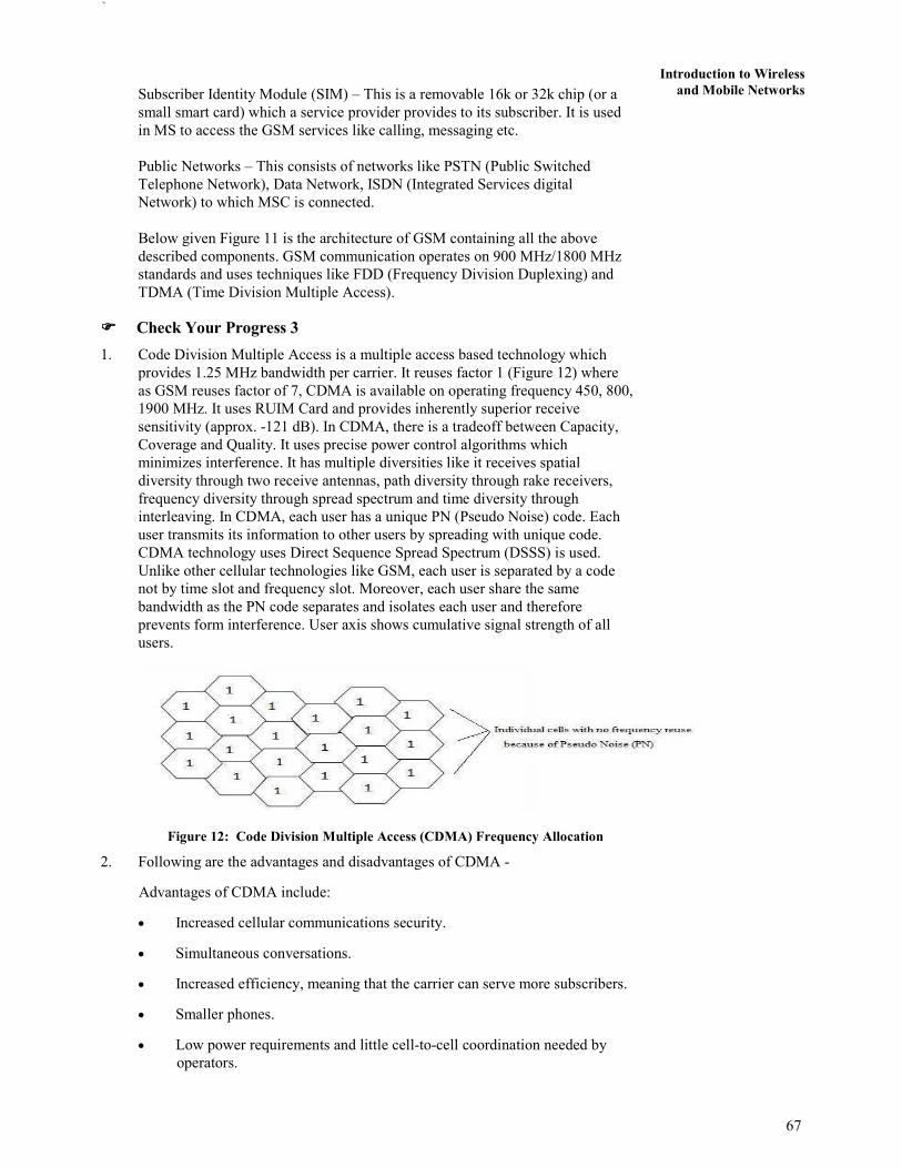
`
67
Introduction to Wireless
and Mobile Networks
Subscriber Identity Module (SIM) – This is a removable 16k or 32k chip (or a
small smart card) which a service provider provides to its subscriber. It is used
in MS to access the GSM services like calling, messaging etc.
Public Networks – This consists of networks like PSTN (Public Switched
Telephone Network), Data Network, ISDN (Integrated Services digital
Network) to which MSC is connected.
Below given Figure 11 is the architecture of GSM containing all the above
described components. GSM communication operates on 900 MHz/1800 MHz
standards and uses techniques like FDD (Frequency Division Duplexing) and
TDMA (Time Division Multiple Access).
���� Check Your Progress 3
1. Code Division Multiple Access is a multiple access based technology which
provides 1.25 MHz bandwidth per carrier. It reuses factor 1 (Figure 12) where
as GSM reuses factor of 7, CDMA is available on operating frequency 450, 800,
1900 MHz. It uses RUIM Card and provides inherently superior receive
sensitivity (approx. -121 dB). In CDMA, there is a tradeoff between Capacity,
Coverage and Quality. It uses precise power control algorithms which
minimizes interference. It has multiple diversities like it receives spatial
diversity through two receive antennas, path diversity through rake receivers,
frequency diversity through spread spectrum and time diversity through
interleaving. In CDMA, each user has a unique PN (Pseudo Noise) code. Each
user transmits its information to other users by spreading with unique code.
CDMA technology uses Direct Sequence Spread Spectrum (DSSS) is used.
Unlike other cellular technologies like GSM, each user is separated by a code
not by time slot and frequency slot. Moreover, each user share the same
bandwidth as the PN code separates and isolates each user and therefore
prevents form interference. User axis shows cumulative signal strength of all
users.
Figure 12: Code Division Multiple Access (CDMA) Frequency Allocation
2. Following are the advantages and disadvantages of CDMA -
Advantages of CDMA include:
• Increased cellular communications security.
• Simultaneous conversations.
• Increased efficiency, meaning that the carrier can serve more subscribers.
• Smaller phones.
• Low power requirements and little cell-to-cell coordination needed by
operators.
68
Concepts of
Communication and
Networking
Network Transport
and Application
Layer
• Extended reach - beneficial to rural users situated far from cells.
• Uses Direct Sequence Spread Spectrum (DSSS) technology
• Provides soft & softer handoff of a user crossing between cellular region
• Uses rake receiver
• Has a variable rate vocoder
• Provides high quality voice to its users
• Has power control
• Gives better coverage area network
• Has a very simple network planning of cells
• Provides smooth migration to 3G and the operator’s benefit is protected.
Disadvantages of CDMA include:
• Due to its proprietary nature, all of CDMA's flaws are not known to the
engineering community.
• CDMA is relatively new, and the network is not as mature as GSM.
• CDMA cannot offer international roaming, a large GSM advantage
���� Check Your Progress 4
1. i) False
ii) True
iii) False
iv) False
iv) False.
2. Co-Channel Interference is caused due to the frequency reuse phenomenon as
the base stations which are operating at the same frequency causes
interference. As described above the concept of frequency reuse, each cells has
base stations which are operating on frequencies. This interference degrades the
receiver performance as the signal arrives from both intended transmitter and
undesired transmitter which is operating on same frequency.
Adjacent Channel Interference is caused by extraneous power from a signal in
an adjacent channel and is caused due to the base stations which are operating
at adjacent frequencies. The reason behind this interference can be inadequate
filtering, improper tuning or poor frequency control. This can be handled by
applying the technologies like proper channel assignment and careful filtering.
Data Encryption Standard (DES) is a symmetric-key block cipher published by
the National Institute of Standards and Technology (NIST) in 1977. DES has
been the most widely used symmetric-key block cipher since its publication.
3. Cell Sectoring – As the name suggests, a single cell is divided into small sectors
at angle of 120 degree or 60 degree. When a cell is sectored into three small
cells, this sectoring is called 120 degree sectoring. When a cell is sectored into
six small cells, this sectoring is called 60 degree sectoring (Figure 15 & 16).
This is an another way of improving capacity of a particular cell. Moreover, 120
degree sectoring reduces co-channel interference as the antennas used in the
technology are directional antennas and not omni-directional antenna.
`
69
Introduction to Wireless
and Mobile NetworksDirectional antenna signals are directed in the particular direction where as an
Omni-directional antenna signals are directed in all directions equally.

70
Concepts of
Communication and
Networking
UNIT 4 NETWORK SECURITY
Structure Page Nos.
4.0 Introduction to Security 70
4.1 Objectives 71
4.2 Types of Security 71 4.2.1 Application Security
4.2.2 Computer Security
4.2.3 Data Security
4.2.4 Information Security
4.2.5 Network Security
4.3 Need of Security 72
4.4 Security Services 73 4.4.1 Confidentiality
4.4.2 Availability
4.4.3 Integrity
4.4.4 Authentication
4.4.5 Non-Repudiation
4.4.6 Other Services
4.5 Authentication and Privacy 74
4.6 Block Cipher and Stream Cipher 77
4.7 Public and Private Key Cryptography 79
4.8 Introduction to RSA, DES and MD5 81
4.9 Summary 84
4.10 Suggested Reading 84
4.11 Solutions/Answers 85
4.0 INTRODUCTION TO SECURITY
Use of technology among people is increasing day by day. Such technologies are
Computers, Internet (or Network), Mobile phone, Laptops, Tablets, Hard-disk etc.
These technologies have internal and external memory which contains electronic data.
This data can be confidential, public or private. Now, the security of such data
becomes mandatory for all users so as to prevent it from any form of attack which can
make this data corrupted. Therefore, Security is a very essential part of day-to-today
activities. Now, we will start with defining the term “Security”.
Security can be defined by the following statements –
• the state of being secure
• precautions taken to ensure against theft, espionage, etc
• protection of assets
• free from danger or attack or threat
• form of protection
Overall, Security ensures that all processes work as expected. It is the most critical
factor and has minimal standard which should be maintained by an individual or
organization. This brings reliability, safety and assurance of being protected.
In this unit, you will be introduced to types of security and its services like
Confidentiality, Availability, Integrity, Authentication, and Non-Repudiation etc. In
addition, you will be introduced to the concepts of Cryptography and Cryptology
which further define the way in which encryption and decryption can be done. Also,
Public and Private Key Cryptography are introduced at later stages. Finally, we will
discuss about the Public and Private Key Cryptography algorithms like RSA, DES and
MD5.

71
Network Security 4.1 OBJECTIVES
After going through this unit you will be able to:
• define the Security and its types;
• define the Security Services;
• discuss Block cipher and Stream Cipher;
• define the define the Cryptography and Cryptology
• define Public and Private Key Cryptography; and
• Define RSA, DES and MD5.
4.2 TYPES OF SECURITY
Information Technology (IT) Security – consists of following types:
1. Application security,
2. Computer security,
3. Data security,
4. Information security
5. Network security
4.2.1 Application Security
Application security prevents attack and vulnerabilities on an application. This
application can be a mobile application or any other application such as web
application etc. The security of an application remains throughout its lifecycle from
initial phase to its running phase (or application phase) and on maintenance phase too.
4.2.2 Computer Security
Computer security is about securing a computer system (Desktop or Laptop etc) or a
host. This type of security ensures a computer virus free with the help of an anti-virus
software. Moreover, a computer should use genuine and updated software and
hardware. Also it should be protected with a password. This type of security is a form
of computer security.
4.2.3 Data Security
Data Security involves security of electronic data which is present on any hard-disks /
secondary storage either of computer system or on network, on server, etc. Such
security can be implemented by using passwords, cryptography (through encryption
and decryption), biometric authentication, or through access control list etc.
4.2.4 Information Security
Information Security is defined as protection of information and information
systems from unauthorized access, use, disclosure, disruption, modification, perusal,
inspection, recording or destruction. This involves security of electronic data which is
present on any database or file in any electronic memory. “Data Security” and
“Information Security” are used interchangeably and are almost similar.
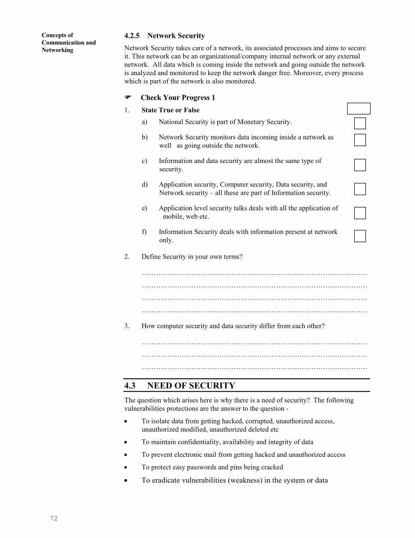
72
Concepts of
Communication and
Networking
4.2.5 Network Security
Network Security takes care of a network, its associated processes and aims to secure
it. This network can be an organizational/company internal network or any external
network. All data which is coming inside the network and going outside the network
is analyzed and monitored to keep the network danger free. Moreover, every process
which is part of the network is also monitored.
���� Check Your Progress 1
1. State True or False
a) National Security is part of Monetary Security.
b) Network Security monitors data incoming inside a network as
well as going outside the network.
c) Information and data security are almost the same type of
security.
d) Application security, Computer security, Data security, and
Network security – all these are part of Information security.
e) Application level security talks deals with all the application of
mobile, web etc.
f) Information Security deals with information present at network
only.
2. Define Security in your own terms?
……………………………………………………………………………………
……………………………………………………………………………………
……………………………………………………………………………………
……………………………………………………………………………………
3. How computer security and data security differ from each other?
……………………………………………………………………………………
……………………………………………………………………………………
……………………………………………………………………………………
4.3 NEED OF SECURITY
The question which arises here is why there is a need of security? The following
vulnerabilities protections are the answer to the question -
• To isolate data from getting hacked, corrupted, unauthorized access,
unauthorized modified, unauthorized deleted etc
• To maintain confidentiality, availability and integrity of data
• To prevent electronic mail from getting hacked and unauthorized access
• To protect easy passwords and pins being cracked
• To eradicate vulnerabilities (weakness) in the system or data

73
Network Security 4.4 SECURITY SERVICES
In order to overcome the above mentioned vulnerabilities of a system or data or
network etc, there are 5 major security services (Figure 1) – Confidentiality, Integrity,
Availability, Non-Repudiation and Authentication which are as follows:
Figure 1: Security Services
4.4.1 Confidentiality
Confidentiality means keeping information secret from unauthorized access and is
probably the most common aspect of information security. It is important to protect
confidential information. An organization needs to guard against those malicious
actions that endanger the confidentiality of its information. For example, an account
user is authorized to see his account transaction online and no other account user can
access this data as it is confidential.
4.4.2 Integrity
Information needs to be changed constantly. In a bank, when a customer deposits or
withdraws money, the balance of their account needs to be changed. Integrity means
that changes should be done only by authorized users and through authorized
mechanisms. Moreover, the changes should get reflected at all the ends on which the
changed information is accessed.
4.4.3 Availability
The third component of information security services is availability. The information
created and stored by an organization needs to be available to authorized users and
applications. Information is useless if it is not available o authorized users.
Information needs to be changed constantly, which means that it must be accessible to
those authorized to access it. Unavailability of information is just as harmful to an
organization as a lack of confidentiality or integrity. Imagine what would happen to a
bank if the customers could not access their accounts for transactions. Therefore,
information should be accessible and useable upon appropriate demand by an
authorized user and availability is the prevention of unauthorized withholding of
information.
4.4.4 Authentication
Authentication is the process by which a person or other entity proves that it is who
(or what) it says it is. For example, a bank authenticates a person or entity that deal
before transferring something valuable, such as information or money, to or from, it.
Authentication is achieved by presenting some unique identifying entity to the
endpoint that is undertaking the process. An example of this process is the way you
authenticate yourself with an ATM - here you insert your bank card (something you
have) and enter your personal identification number (PIN –Personal Identification
Number, something you know). Another example can be the authentication process
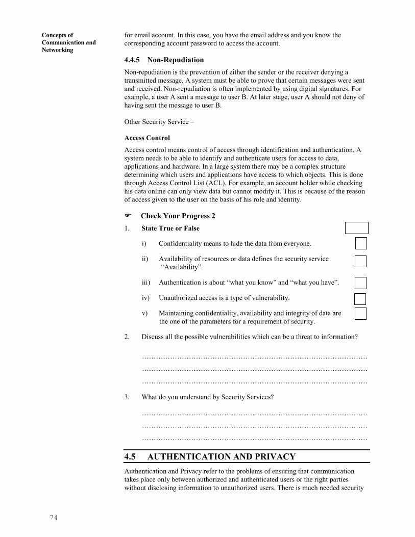
74
Concepts of
Communication and
Networking
for email account. In this case, you have the email address and you know the
corresponding account password to access the account.
4.4.5 Non-Repudiation
Non-repudiation is the prevention of either the sender or the receiver denying a
transmitted message. A system must be able to prove that certain messages were sent
and received. Non-repudiation is often implemented by using digital signatures. For
example, a user A sent a message to user B. At later stage, user A should not deny of
having sent the message to user B.
Other Security Service –
Access Control
Access control means control of access through identification and authentication. A
system needs to be able to identify and authenticate users for access to data,
applications and hardware. In a large system there may be a complex structure
determining which users and applications have access to which objects. This is done
through Access Control List (ACL). For example, an account holder while checking
his data online can only view data but cannot modify it. This is because of the reason
of access given to the user on the basis of his role and identity.
���� Check Your Progress 2
1. State True or False
i) Confidentiality means to hide the data from everyone.
ii) Availability of resources or data defines the security service
“Availability”.
iii) Authentication is about “what you know” and “what you have”.
iv) Unauthorized access is a type of vulnerability.
v) Maintaining confidentiality, availability and integrity of data are
the one of the parameters for a requirement of security.
2. Discuss all the possible vulnerabilities which can be a threat to information?
……………………………………………………………………………………
……………………………………………………………………………………
……………………………………………………………………………………
3. What do you understand by Security Services?
……………………………………………………………………………………
……………………………………………………………………………………
……………………………………………………………………………………
4.5 AUTHENTICATION AND PRIVACY
Authentication and Privacy refer to the problems of ensuring that communication
takes place only between authorized and authenticated users or the right parties
without disclosing information to unauthorized users. There is much needed security

75
Network Security infrastructure in place for authentication and privacy based on well known techniques
in symmetric and asymmetric cryptography.
Authentication as explained in previous section is all about identifying the user and
based on his identification, giving access and rights to the user. In this section, we will
discuss about how an authentication can be done with the help of identification.
Authentication-Identification
Identification is all about being able to identify yourself to a computer and is
absolutely essential -
• ATM, e-banking identifies a user with the help of PIN
• Access to e-mail, computer accounts, identifies a user with the help of a
password
• Access to personal information (e.g., staff or student portal)
Non-computer identification
• Bank teller knows you by sight
• Bank teller checks your picture against a photo ID
• Bank back office compares cheque signature to one on record
• All examples of biometric identification.
Computer Identification
• How we identify a human to a computer?
• Username/Passwords (common),
• Token, e.g. ATM card,
• Cryptographic protocols,
• Combinations, e.g. token and password,
• Biometrics, e.g. face recognition, finger prints, and retina/iris scans
Privacy
Handling user privacy and maintaining user security are tough tasks to do. In most of
the cases, it is done through a technique called “Cryptography”.
Cryptography is defined as a process of conversion of plain and readable text to
cipher and (unreadable) text called encryption. For example, in Figure 2, the plain text
“I am doing bca from ignou” is converted to cipher text “L dp grlqj efd iurp ljqrx” by
using Caesar cipher cryptographic algorithm.
Figure 2: Process of Encryption

76
Concepts of
Communication and
Networking
Decryption is the process of converting cipher and unreadable text to plain and
readable text (called decryption). In given Figure 3, cipher text “L dp grlqj efd iurp
ljqrx” is converted to plain text “I am doing bca from ignou” with the help of
decryption process.
Please note – Both the process “Encryption” and “Decryption” are performed with the
help of a key. Either the same key is used for both encryption (called symmetric or
private key encryption) or separate keys (one for encryption and other one for
decryption) are used called the asymmetric or public key encryption.
Figure 3: Process of Decryption
Cryptanalysis is the reverse process of cryptography. It means an attacker tries to
find the plain text from captured cipher text. But the attacker does this without any
key. The key is secured and attacker does not have any kind of access to the key. He
only has the cipher text on which he applies reverse engineering.
Please Note – There is a very little difference between “Decryption” and
“Cryptanalysis” as in both the cases, the aim is to know or to find the plain text
behind cipher text. In decryption, the key is always available to the user who wants to
decrypt the cipher text. But in case of cryptanalysis, there is no such key available to
decrypt cipher text. In this situation, it is the attacker and not the user who wants to
find the cipher text “without key” in order to break the cipher algorithm which is used
to convert the plain text into an unreadable cipher text. The main motive is to attack
the system with wrong intensions. In case of decryption part, the user uses the key to
decrypt the plain text and there is no such wrong intension. The user with a key is
always considered as right or authoritive person to decrypt the cipher text into its
corresponding plain text.
Cryptology is the combination of Cryptography and Cryptanalysis (Figure 4).
Figure 4: Cryptology
Cryptography - the process of encryption can be Symmetric (Secret Key or Private
Key) and Asymmetric which will be discussed in detail in coming sections.
���� Check Your Progress 3
1. How “Authentication” can be proved through “Identification”?
……………………………………………………………………………………
……………………………………………………………………………………
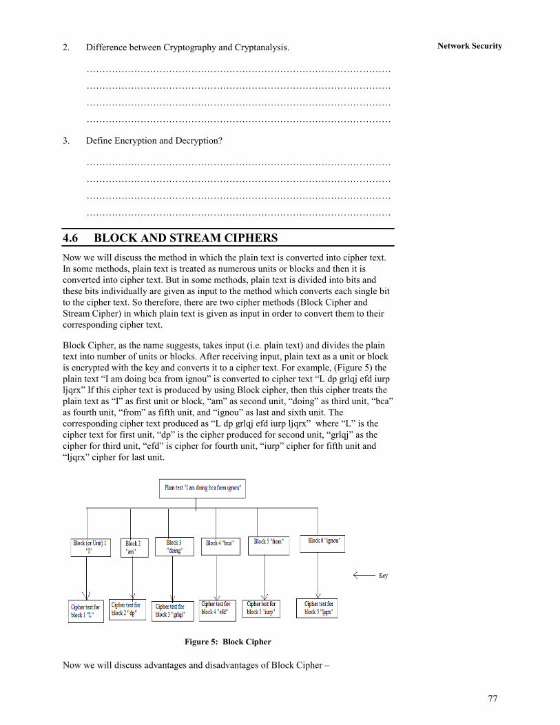
77
Network Security 2. Difference between Cryptography and Cryptanalysis.
……………………………………………………………………………………
……………………………………………………………………………………
……………………………………………………………………………………
……………………………………………………………………………………
3. Define Encryption and Decryption?
……………………………………………………………………………………
……………………………………………………………………………………
……………………………………………………………………………………
……………………………………………………………………………………
4.6 BLOCK AND STREAM CIPHERS
Now we will discuss the method in which the plain text is converted into cipher text.
In some methods, plain text is treated as numerous units or blocks and then it is
converted into cipher text. But in some methods, plain text is divided into bits and
these bits individually are given as input to the method which converts each single bit
to the cipher text. So therefore, there are two cipher methods (Block Cipher and
Stream Cipher) in which plain text is given as input in order to convert them to their
corresponding cipher text.
Block Cipher, as the name suggests, takes input (i.e. plain text) and divides the plain
text into number of units or blocks. After receiving input, plain text as a unit or block
is encrypted with the key and converts it to a cipher text. For example, (Figure 5) the
plain text “I am doing bca from ignou” is converted to cipher text “L dp grlqj efd iurp
ljqrx” If this cipher text is produced by using Block cipher, then this cipher treats the
plain text as “I” as first unit or block, “am” as second unit, “doing” as third unit, “bca”
as fourth unit, “from” as fifth unit, and “ignou” as last and sixth unit. The
corresponding cipher text produced as “L dp grlqj efd iurp ljqrx” where “L” is the
cipher text for first unit, “dp” is the cipher produced for second unit, “grlqj” as the
cipher for third unit, “efd” is cipher for fourth unit, “iurp” cipher for fifth unit and
“ljqrx” cipher for last unit.
Figure 5: Block Cipher
Now we will discuss advantages and disadvantages of Block Cipher –

78
Concepts of
Communication and
Networking
Advantages of Block Cipher -
• It is faster than stream cipher.
• If any block contains any transmission error then it will not have affect on other
blocks.
• It is not sufficient in hardware but may be used to connect keyboard to CPU
(central process unit)
• Block ciphers can be easier to implement in software, because there is no bit
manipulation like in stream cipher which is time consuming process and treats
data in computer-sized blocks
• Block Cipher is more suitable in trading applications.
• Short blocks at the end of a message can also be added with blank or zero
status.
Disadvantages of Block Cipher -
• If two same unit or blocks of plaintext is there, then the cipher produces same
cipher text for units or blocks.
• It is easy to insert or delete units/blocks .
• Block encryption may be more susceptible to cryptanalysis attack as compared
to stream cipher as block cipher provides strong hints to attacker because two
same units produce same cipher text.
• Block encryption is more susceptible to replay as compared to stream
encryption.
Stream Cipher takes input (i.e. plain text) and divide this plain text into number of bits
(combination of such bits is palin text). After receiving single bit which represents as
a part of plain text is encrypted with the key and converts it to a cipher text. For
example, ( Figure 6) the plain text “I am doing bca from ignou” is converted to cipher
text “L dp grlqj efd iurp ljqrx” If this cipher text is produced by using Stream cipher,
then this cipher treats each alphabet as a single bit and converts each bit one after
another to cipher text. “I” as first bit, “a” as second bit, “m” as third bit, “d” as fourth
bit, “o” as fifth bit and so on. The corresponding cipher text produced as “L dp grlqj
efd iurp ljqrx” where “L” is the cipher text for first bit, “d” for second bit, “p” is the
cipher produced for third bit, “g” cipher text for fourth bit, “r” cipher for fifth bit and
so on like this. Please note that we have taken this example for simplicity. Also we
have used Caesar cipher cryptographic algorithm for both the stream.
Figure 6: Stream Cipher

79
Network Security Now we will discuss advantages and disadvantages of Stream Cipher –
Advantages of Stream Cipher -
• Stream cipher is suitable for hardware implementation as only encryption and
decryption data one bit at a time.
• Stream cipher is less susceptible to cryptanalysis than block cipher as block
cipher provides strong hints to attacker because two same units produce same
cipher text.
• Stream cipher is less to vulnerable to insertion or deletion of units.
• This cipher can be more easily analyzed mathematically.
• It is more suitable for military applications.
• It is less useful for attackers as same plain text is encrypted but in single
individual bits and not in units.
• Self-synchronous stream ciphers are non-periodic because each key character is
function dependent on the entire preceding message stream.
• Self – synchronous cipher protect against all type of authenticity threats because
any change to the cipher text affects the key stream
Disadvantage of Stream Cipher -
• If during transmission, any bit is lost or become erroneous, then it is difficult to
re-arrange and collect all the converted cipher text which in return may result in
re-transmission of the entire plain text.
• It is slower than block but can be configured to make faster by implemented in
special purpose hardware capable of encryption several million bits for second.
• It is not suitable for the software.
4.7 PUBLIC AND PRIVATE KEY CRYPTOGRAPHY
Encryption and Decryption:
Encryption is the conversion of data into a form, called a ciphertext, which cannot be
easily understood by unauthorised entities whereas Decryption is the process of
converting encrypted data back into its original form, so it can be understood.
Most security technologies rely, to some degree, on encryption of text or data. For
example, encryption is used in the creation of certificates and digital signatures, for
the secure storage of secrets or transport of information. Encryption can be anything
from a simple process of substituting one character for another, in which case the key
is the substitution rule, to some complex mathematical algorithm. It is to be assumed
that the more difficult is to decrypt the ciphertext, the better. Trade-off - if the
algorithm is too complex and it takes too long to use, or requires keys that are too
large to store easily, it becomes impractical to use. There is a need a balance between
the strength of the encryption; that is, how difficult it is for someone to discover the
algorithm and the key, and ease of use. There are two main types of encryption in use
for computer security, referred to as symmetric and asymmetric key encryption.
Symmetric Key
Symmetric key cryptography, also called private or secret key cryptography, is the
classic cryptographic use of keys:
Here the same key is used to encrypt and decrypt the data. In given Figure 7, User A
and User B both uses same secret/shared key to encrypt and decrypt the message.
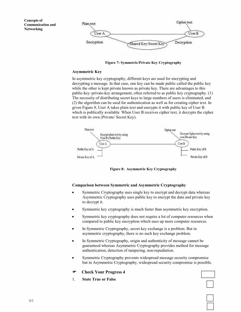
80
Concepts of
Communication and
Networking
Figure 7: Symmetric/Private Key Cryptography
Asymmetric Key
In asymmetric key cryptography, different keys are used for encrypting and
decrypting a message. In that case, one key can be made public called the public key
while the other is kept private known as private key. There are advantages to this
public-key–private-key arrangement, often referred to as public key cryptography. (1)
The necessity of distributing secret keys to large numbers of users is eliminated, and
(2) the algorithm can be used for authentication as well as for creating cipher text. In
given Figure 8, User A takes plain text and encrypts it with public key of User B
which is publically available. When User B receives cipher text, it decrypts the cipher
text with its own (Private/ Secret Key).
Figure 8: Asymmetric Key Cryptography
Comparison between Symmetric and Asymmetric Cryptography
• Symmetric Cryptography uses single key to encrypt and decrypt data whereas
Asymmetric Cryptography uses public key to encrypt the data and private key
to decrypt it.
• Symmetric key cryptography is much faster than asymmetric key encryption.
• Symmetric key cryptography does not require a lot of computer resources when
compared to public key encryption which uses up more computer resources.
• In Symmetric Cryptography, secret key exchange is a problem. But in
asymmetric cryptography, there is no such key exchange problem.
• In Symmetric Cryptography, origin and authenticity of message cannot be
guaranteed whereas Asymmetric Cryptography provides method for message
authentication, detection of tampering, non-repudiation.
• Symmetric Cryptography prevents widespread message security compromise
but in Asymmetric Cryptography, widespread security compromise is possible.
���� Check Your Progress 4
1. State True or False

81
Network Security i) Symmetric Key Cryptography uses two different key for
encryption and decryption.
ii) Block Cipher is slower than Stream Cipher.
iii) Public key and Private key are the part of asymmetric key
cryptography.
iv) Cipher text is the output of the process called “Encryption”.
v) Authenticity of messages is guaranteed by asymmetric key
Cryptography.
2. Discuss advantages and disadvantages of Block and Stream Ciphers?
……………………………………………………………………………………
……………………………………………………………………………………
……………………………………………………………………………………
……………………………………………………………………………………
……………………………………………………………………………………
3. State the difference between Symmetric and Asymmetric Cryptography?
……………………………………………………………………………………
……………………………………………………………………………………
……………………………………………………………………………………
……………………………………………………………………………………
……………………………………………………………………………………
4.8 INTRODUCTION TO RSA, MD5 AND DES
Data Encryption Standard (DES)
Data Encryption Standard (DES) was developed as a standard for communications
and data protection by an IBM research team, in response to a public request for
proposals by the NBS - the National Bureau of Standards (which is now known as
NIST). DES was developed in the 1970s by the National Bureau of Standards with the
help of the National Security Agency. Its purpose is to provide a standard method for
protecting sensitive commercial and unclassified data. IBM created the first draft of
the algorithm, calling it LUCIFER. DES officially became a federal standard in
November of 1976.
The Data Encryption Standard (DES) is a symmetric-key block cipher published by
the National Institute of Standards and Technology (NIST) in 1977. DES has been the
most widely used symmetric-key block cipher since its publication.
DES takes 64 bit plain text converts it into 64 bit cipher text with the help of 64 bit
key (Figure 9) which is later reduced to 56 bit key as every 8th bit of 64 bit is
discarded to form a key of 54 bit. As DES is a block cipher, it takes plain text as block
of 64 bit.
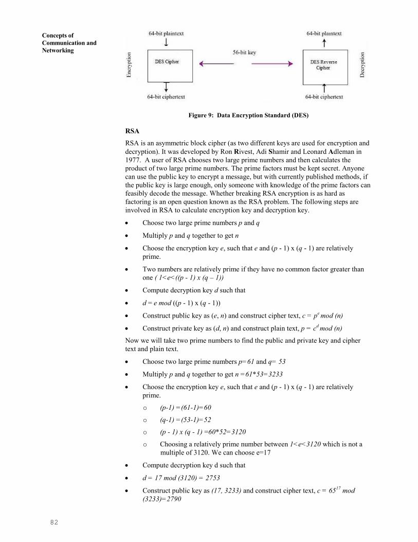
82
Concepts of
Communication and
Networking
Figure 9: Data Encryption Standard (DES)
RSA
RSA is an asymmetric block cipher (as two different keys are used for encryption and
decryption). It was developed by Ron Rivest, Adi Shamir and Leonard Adleman in
1977. A user of RSA chooses two large prime numbers and then calculates the
product of two large prime numbers. The prime factors must be kept secret. Anyone
can use the public key to encrypt a message, but with currently published methods, if
the public key is large enough, only someone with knowledge of the prime factors can
feasibly decode the message. Whether breaking RSA encryption is as hard as
factoring is an open question known as the RSA problem. The following steps are
involved in RSA to calculate encryption key and decryption key.
• Choose two large prime numbers p and q
• Multiply p and q together to get n
• Choose the encryption key e, such that e and (p - 1) x (q - 1) are relatively
prime.
• Two numbers are relatively prime if they have no common factor greater than
one ( 1<e<((p - 1) x (q – 1))
• Compute decryption key d such that
• d = e mod ((p - 1) x (q - 1))
• Construct public key as (e, n) and construct cipher text, c = pe mod (n)
• Construct private key as (d, n) and construct plain text, p = cd mod (n)
Now we will take two prime numbers to find the public and private key and cipher
text and plain text.
• Choose two large prime numbers p=61 and q= 53
• Multiply p and q together to get n =61*53=3233
• Choose the encryption key e, such that e and (p - 1) x (q - 1) are relatively
prime.
o (p-1) =(61-1)=60
o (q-1) =(53-1)=52
o (p - 1) x (q - 1) =60*52=3120
o Choosing a relatively prime number between 1<e<3120 which is not a
multiple of 3120. We can choose e=17
• Compute decryption key d such that
• d = 17 mod (3120) = 2753
• Construct public key as (17, 3233) and construct cipher text, c = 6517 mod
(3233)=2790

83
Network Security • Construct private key as (2753, 3233) and construct plain text, p = 27902753
mod (3233)=65
Message Digest5
Before starting MD5, we will first discuss about has Hash Functions which takes
input a plain text or a message and converts it to a hash value with the help of hash
algorithm. Hash Functions are called “One-way Functions” as the hash value, which
is the result of converted plain text, cannot be converted back to the plain text or
message. Every message produces different hash value. No two different plain
messages can have same hash value. Similarly, One hash value belongs to one plain
text message only.
The MD5 Message-Digest Algorithm is a widely used cryptographic hash
function that produces a 128-bit (16-byte) hash value. MD5 has been employed in a
wide variety of security applications, and is also commonly used to check data
integrity. MD5 was designed by Ron Rivest in 1991 to replace an earlier hash
function, MD4. An MD5 hash is typically expressed as a hexadecimal number, 32
digits long. The following are the steps for Message Digest 5 algorithm –
MD5 takes input of arbitrary length and gets broken into blocks of size 512 bits. It
produces output of 128 bits.
• Append padding bits so length ≡ 448 mod 512 (padded message 64 bits less
than an integer multiplied by 512)
• Append length: a 64-bit representation of the length to the original message
(before the padding) � total length of message k*512 bits
• Initialize MD buffer: 128-bit buffer holds intermediate and final results (4 32-
bit registers, ABCD)
• Process message in 512-bit blocks
• 4 rounds of processing
• Similar structure but different logical function
• Each round takes the 512-bit input and values of ABCD and modifies ABCD
• Output: from the last stage is a 128-bit digest
• Every bit of plain text influences every bit of the the hash code
• Complex repetition of the basic functions � unlikely that two random messages
would have similar regularities
• MD5 is as strong as possible for 128-bit digest (Rivest’s conjecture)
Cryptographic checksum is just as a regular checksum protects the receiver from
accidental changes to the message, a cryptographic checksum protects the receiver
from malicious changes to the message. One-way function given a cryptographic
checksum for a message, it is virtually impossible to figure out what message
produced that checksum; it is not computationally feasible to find two messages that
hash to the same cryptographic checksum.
If you are given a checksum for a message and you are able to compute exactly the
same checksum for that message, then it is highly likely this message produced the
checksum you were given.
���� Check Your Progress 5

84
Concepts of
Communication and
Networking
1. State True or False
1. Data Encryption Standard (DES) is a symmetric-key block
cipher.
2. RSA was developed in 1978.
3. RSA is an example of symmetric-key block cipher.
4. RSA takes two large prime numbers as its input.
5. Message Digest 5 (MD5) is a “One-way hash function”.
2. Discuss about Data Encryption Standard (DES)?
……………………………………………………………………………………
……………………………………………………………………………………
……………………………………………………………………………………
……………………………………………………………………………………
3. Explain RSA with the help of an example?
……………………………………………………………………………………
……………………………………………………………………………………
……………………………………………………………………………………
……………………………………………………………………………………
4.9 SUMMARY
This completes our discussion on the introductory concepts of Security. The Security
Services discussed in the unit are the basic mandatory services but there can be other
services for security. There are many other services such as Accessibility,
Authorization etc. Moreover, the security and various cryptography algorithms are
introduced and designed in order to prevent passive and active attacks like Man-in-
the-middle attack, Brute Force attack, Denial of Service (DOS), Distributed Denial of
Service (DDOS), Virus, Worm, Trojan Horse etc.
The information given on various topics such as Cryptographic Algorithm, Block and
Stream Ciphers, Security attacks, Vulnerabilities, RSA, DES, MD5 etc is exhaustive
yet can be supplemented with additional reading. However, Security is an emerging
field and implementation of security can be achieved by using various security tools
like Intrusion Detection and Prevention Systems (IDPS), Encase, Process Viewer etc.
4.10 SUGGESTED READING
• Stallings, William 2006. Cryptography and Network Security. Fourth Edition,
Pearson Prentice Hall Cambridge: Pearson Education Inc .
• Kahate, Atul. 2003. Cryptography and Network Security. Tata McGraw-Hill
Publication.
• Schneier, Bruce. 2008. “Schneier on Security” Wiley Publications.
• Ferguson, Niels. Schneier, Bruce. and Kohno, Tadayoshi. 2010. Cryptography
Engineering, John Wiley & Sons
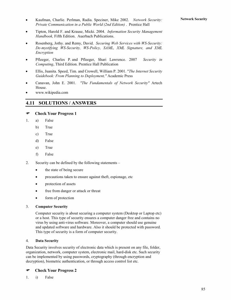
85
Network Security • Kaufman, Charlie. Perlman, Radia. Speciner, Mike 2002. Network Security:
Private Communication in a Public World (2nd Edition) . Prentice Hall
• Tipton, Harold F. and Krause, Micki. 2004. Information Security Management
Handbook, Fifth Edition. Auerbach Publications.
• Rosenberg, Jothy. and Remy, David. Securing Web Services with WS-Security:
De-mystifying WS-Security, WS-Policy, SAML, XML Signature, and XML
Encryption
• Pfleeger, Charles P. and Pfleeger, Shari Lawrence. 2007 Security in
Computing, Third Edition. Prentice Hall Publication
• Ellis, Juanita. Speed, Tim. and Crowell, William P. 2001. "The Internet Security
Guidebook: From Planning to Deployment," Academic Press
• Canavan, John E. 2001. "The Fundamentals of Network Security" Artech
House.
• www.wikipedia.com
4.11 SOLUTIONS / ANSWERS
���� Check Your Progress 1
1. a) False
b) True
c) True
d) False
e) True
f) False
2. Security can be defined by the following statements –
• the state of being secure
• precautions taken to ensure against theft, espionage, etc
• protection of assets
• free from danger or attack or threat
• form of protection
3. Computer Security
Computer security is about securing a computer system (Desktop or Laptop etc)
or a host. This type of security ensures a computer danger free and contains no
virus by using anti-virus software. Moreover, a computer should use genuine
and updated software and hardware. Also it should be protected with password.
This type of security is a form of computer security.
4. Data Security
Data Security involves security of electronic data which is present on any file, folder,
organization, network, computer system, electronic mail, hard-disk etc. Such security
can be implemented by using passwords, cryptography (through encryption and
decryption), biometric authentication, or through access control list etc.
���� Check Your Progress 2
1. i) False

86
Concepts of
Communication and
Networking
ii) True
iii) True
iv) True
v) False.
2. Following are the Vulnerabilities -
• To isolate data from getting hacked, corrupted, unauthorized access,
unauthorized modified, unauthorized deleted etc
• To maintain confidentiality, availability and integrity of data
• To prevent electronic mail from getting hacked and unauthorized access
• To protect easy passwords and pins being cracked
• To eradicate vulnerabilities (weakness) in the system or data
3. In order to overcome all the vulnerabilities of a system or data or network etc,
there are 5 major security services – Confidentiality, Integrity, Availability,
Non-Repudiation and Authentication. If all these five basic security services are
ensured then the system or network or data will be free of virus, danger etc.
���� Check Your Progress 3
1. Authentication-Identification
Identification is all about being able to identify yourself to a computer and is
absolutely essential -
• ATM, e-banking identifies a user with the help of PIN
• Access to e-mail, computer accounts, identifies a user with the help of a
password
• Access to personal information (e.g., staff or student portal)
Non-computer identification
• Bank teller knows you by sight
• Bank teller checks your picture against a photo ID
• Bank back office compares cheque signature to one on record
• All examples of biometric identification.
Computer Identification
• How we identify a human to a computer?
• Username/Passwords (common),
• Token, e.g. ATM card,
• Cryptographic protocols,
• Combinations, e.g. token and password,
• Biometrics, e.g. face recognition, finger prints, and retina/iris scans
2. Cryptography is defined as a process of conversion of plain and readable text
to cipher and unreadable text (called encryption). For example, in Figure 2, the
plain text “I am doing bca from ignou” is converted to cipher text “L dp grlqj
efd iurp ljqrx” by using Caesar cipher cryptographic algorithm.

87
Network Security
Cryptanalysis is the reverse process of cryptography. It means an attacker tries
to find the plain text from captured cipher text. But the attacker does this
without any key. The key is secured and attacker does not have any kind of
access to the key. He only has the cipher text on which he will apply reverse
engineering.
3. Encryption is defined as a process of conversion of plain and readable text to
cipher and unreadable text . For example, in figure 3, the plain text “I am doing
bca from ignou” is converted to cipher text “L dp grlqj efd iurp ljqrx” by using
Caesar cipher cryptographic algorithm
Decryption is the process of converting cipher and unreadable text to plain and
readable text (called decryption). In given Figure 3, cipher text “L dp grlqj efd
iurp ljqrx” is converted to plain text “I am doing bca from ignou” with the help
of decryption process..
���� Check Your Progress 4
1. i) False
ii) False
iii) True
iv) False
v) True.
2. Following are the advantages and disadvantages of Block and Stream Cipher -
Advantages of Block Cipher -
• It is faster than stream cipher.
• If any block contains any transmission error then it will not have affect on
other blocks.
• It is not sufficient in hardware but may be used to connect keyboard to
CPU (central process unit)
• Block ciphers can be easier to implement in software, because there is no
bit manipulation like in stream cipher which is time consuming process
and treats data in computer-sized blocks
• Block Cipher is more suitable in trading applications.
• Short blocks at the end of a message can also be added with blank or zero
status.
Disadvantages of Block Cipher -
• If two same unit or blocks of plaintext is there, then the cipher produces
same cipher text for units or blocks.
• It is easy to insert or delete units/blocks .
• Block encryption may be more susceptible to cryptanalysis attack as
compared to stream cipher as block cipher provides strong hints to
attacker because two same units produce same cipher text.
• Block encryption is more susceptible to replay as compare to stream
encryption.
Advantages of Stream Cipher -

88
Concepts of
Communication and
Networking
• Stream cipher is suitable for hardware implementation as only encryption
and decryption data one bit at a time.
• Stream cipher is less susceptible to cryptanalysis than block cipher as
block cipher provides strong hints to attacker because two same units
produce same cipher text.
• Stream cipher is less to vulnerable to insertion or deletion of units.
• This cipher can be more easily analyzed mathematically.
• It is more suitable for military applications.
• It is less useful for attackers as same plain text is encrypted but in single
individual bits and not in units.
• Self-synchronous stream ciphers are non-periodic because each key
character is function dependent on the entire preceding message stream.
• Self – synchronous cipher protect against all type of authenticity threats
because any change to the cipher text affects the key stream
Disadvantage of Stream Cipher -
• If during transmission, any bit is lost or become erroneous, then it is
difficult to re-arrange and collect all the converted cipher text which in
return may result in re-transmission of the entire plain text.
It is slower than block but can be configured to make more fast by implemented
in special purpose hardware capable of encryption several million bits for
second.
• It is not suitable for the software.
3. Comparison between Symmetric and Asymmetric Cryptography
• Symmetric Cryptography uses single key to encrypt and decrypt data
whereas Asymmetric Cryptography uses public key to encrypt the data
and private key to decrypt it.
• Symmetric key cryptography is much faster than asymmetric key
encryption.
• Symmetric key cryptography does not require a lot of computer resources
when compared to public key encryption which uses up more computer
resources.
• In Symmetric Cryptography, secret key exchange is a problem. But in
asymmetric cryptography, there is no suck key exchange problem.
• In Symmetric Cryptography, origin and authenticity of message cannot be
guaranteed whereas Asymmetric Cryptography provides method for
message authentication, detection of tampering, non-repudiation.
• Symmetric Cryptography prevents widespread message security
compromise but in Asymmetric Cryptography, widespread security
compromise is possible.
���� Check Your Progress 5
1. i) True
ii) False

89
Network Security iii) False
iv) True
v) True.
2. The Data Encryption Standard (DES) is a symmetric-key block cipher published
by the National Institute of Standards and Technology (NIST) in 1977. DES has
been the most widely used symmetric-key block cipher since its publication.
DES takes 64 bit plain text converts it into 64 bit cipher text with the help of 64
bit key (Figure 9) which later reduced to 56 bit key as every 8th bit of 64 bit is
discarded to form a key of 54 bit. As DES is a block cipher, it takes plain text as
block of 64 bit.
3. RSA is an asymmetric block cipher ( as two different keys are used for
encryption and decryption). It was developed by Ron Rivest, Adi
Shamir and Leonard Adleman in 1977. Now RSA with an example.
• Choose two large prime numbers p=61 and q= 53
• Multiply p and q together to get n =61*53=3233
• Choose the encryption key e, such that e and (p - 1) x (q - 1) are relatively
prime.
o (p-1) =(61-1)=60
o (q-1) =(53-1)=52
o (p - 1) x (q - 1) =60*52=3120
o Choosing a relatively prime number between 1<e<3120 which is
not a multiple of 3120. We can choose e=17
• Compute decryption key d such that
• d = 17 mod (3120) = 2753
• Construct public key as (17, 3233) and construct cipher text, c = 6517
mod (3233)=2790
• Construct private key as (2753, 3233) and construct plain text, p =
27902753 mod (3233)=65


![Welcome [] · 1 Welcome Message Dear Colleagues ... Prof. Dr. Ihab Hafez Elsawy ... Prof. Hesham Ghazal Associate Prof. Mamdouh Abd-El-Glalil](https://img.pdfslide.us/doc/110x75/5ad8d00e7f8b9a9d5c8dc7c8/welcome-welcome-message-dear-colleagues-prof-dr-ihab-hafez-elsawy-.jpg)