Embed Size (px)
Citation preview
Baseplates and Hg System Handling
V.B. Graves
P.T. Spampinato
MERIT Hg System Safety Review
CERN
June 19-20, 2006
2
OAK RIDGE NATIONAL LABORATORYU. S. DEPARTMENT OF ENERGY
Hg System Safety Review 19-20 June 2006
OAK RIDGE NATIONAL LABORATORYU. S. DEPARTMENT OF ENERGY
Outline
Baseplate descriptions
Design overview
Handling and installation

3
OAK RIDGE NATIONAL LABORATORYU. S. DEPARTMENT OF ENERGY
Hg System Safety Review 19-20 June 2006
OAK RIDGE NATIONAL LABORATORYU. S. DEPARTMENT OF ENERGY
Baseplates
Purpose – provide mobility, alignment, and structural support for experiment components Experiment requires
magnet tilt of 3.8° and elevation ~ 50cm
Four structures Common baseplate Target transporter Target cart Magnet support beam
Primarily fabricated from AL6061-T6
TargetTransporter
TargetCart
CommonBaseplate
Magnet SupportBeam
TargetTransporter
TargetCart
CommonBaseplate
Magnet SupportBeam

4
OAK RIDGE NATIONAL LABORATORYU. S. DEPARTMENT OF ENERGY
Hg System Safety Review 19-20 June 2006
OAK RIDGE NATIONAL LABORATORYU. S. DEPARTMENT OF ENERGY
MERIT Equipment

5
OAK RIDGE NATIONAL LABORATORYU. S. DEPARTMENT OF ENERGY
Hg System Safety Review 19-20 June 2006
OAK RIDGE NATIONAL LABORATORYU. S. DEPARTMENT OF ENERGY
Target Transporter Transports target cart and Hg
system inside tunnel using rollers
Rails for target cart wheels
Jack brackets prevent rolling
Swivel hoist rings for lifting & cart tie-down
Structure shares common baseplate design but is shorter & carries smaller load, so no separate analysis performed

6
OAK RIDGE NATIONAL LABORATORYU. S. DEPARTMENT OF ENERGY
Hg System Safety Review 19-20 June 2006
OAK RIDGE NATIONAL LABORATORYU. S. DEPARTMENT OF ENERGY
Target Cart
Supports Hg system during all phases of experiment
Rollers allow transfer from transporter to common base during integration with magnet
Provides lateral movement of Hg system to maintain alignment with solenoid
Structural analysis performed – Appendix E
7
OAK RIDGE NATIONAL LABORATORYU. S. DEPARTMENT OF ENERGY
Hg System Safety Review 19-20 June 2006
OAK RIDGE NATIONAL LABORATORYU. S. DEPARTMENT OF ENERGY
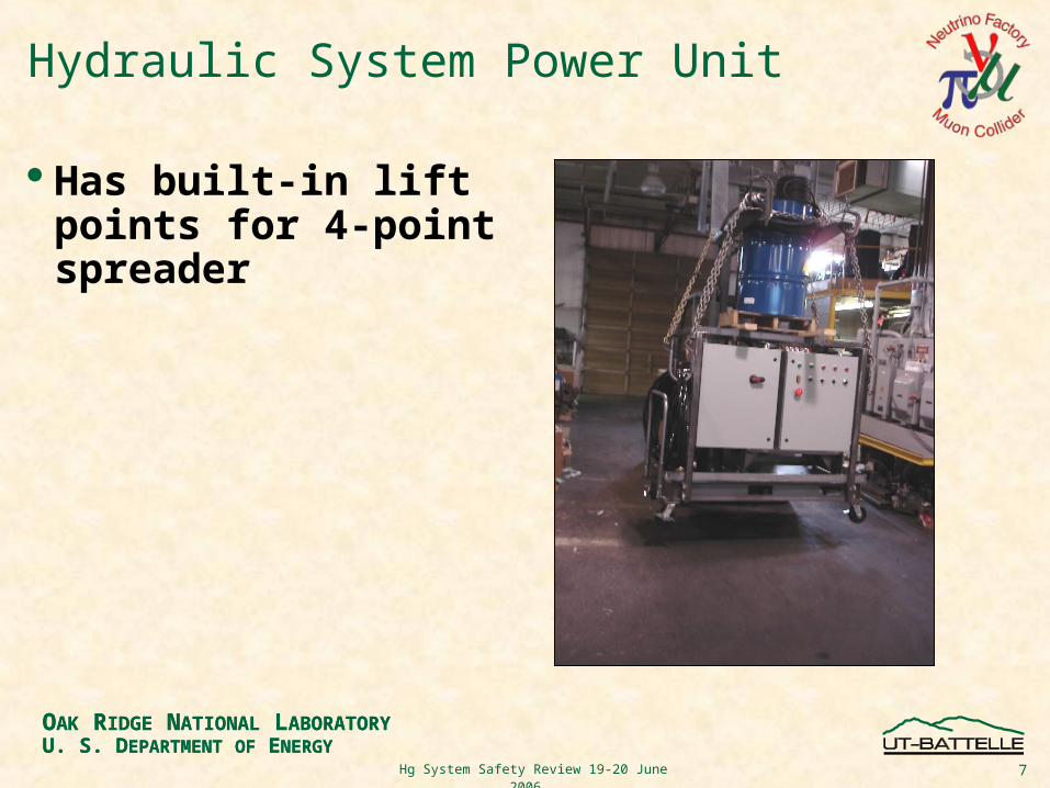
Hydraulic System Power Unit
Has built-in lift points for 4-point spreader

8
OAK RIDGE NATIONAL LABORATORYU. S. DEPARTMENT OF ENERGY
Hg System Safety Review 19-20 June 2006
OAK RIDGE NATIONAL LABORATORYU. S. DEPARTMENT OF ENERGY
Common Baseplate Supports solenoid and Hg system
during experiment Solenoid mobility platform during
installation Rollers used to grossly align solenoid
to beam Provides minor lateral movement of
solenoid for alignment to beam
MagnetRestraints
MagnetLateral
Positioning
LiftingJacks
LevelingJacks
BaseplateLift Points
Rollers
Cart Restraints
AnchorBrackets
TowBrackets

9
OAK RIDGE NATIONAL LABORATORYU. S. DEPARTMENT OF ENERGY
Hg System Safety Review 19-20 June 2006
OAK RIDGE NATIONAL LABORATORYU. S. DEPARTMENT OF ENERGY
Baseplate Design Constraints & Requirements
Total supported weight Solenoid: 5500 kg (12000 lbs) Hg System with 23liter Hg: 1800 kg (4000 lbs) Baseplate: 450 kg (1000 lbs) Movement requires lateral force of 3.8kN (850 lbs) (μs = 0.05 per
roller vendor)
Maximum width of 1.3m (51") to meet CERN facility constraints
Fabrication material to be non-magnetic (chose AL 6061-T6)
Must have lifting provisions for unloaded baseplate

10
OAK RIDGE NATIONAL LABORATORYU. S. DEPARTMENT OF ENERGY
Hg System Safety Review 19-20 June 2006
OAK RIDGE NATIONAL LABORATORYU. S. DEPARTMENT OF ENERGY
Common Baseplate Analyses
Multiple finite-element studies performed to simulate various loading scenarios Transport rollers Lifting brackets Hoisting Leveling feet
Results showed adequate design in all loading conditions simulated
Additional manual calculations performed on specific critical baseplate components Baseplate lifting point welds Hydraulic jacking bracket welds Hg cart restraint brackets
Included in Appendix E

11
OAK RIDGE NATIONAL LABORATORYU. S. DEPARTMENT OF ENERGY
Hg System Safety Review 19-20 June 2006
OAK RIDGE NATIONAL LABORATORYU. S. DEPARTMENT OF ENERGY
Magnet Support Beam
Elevating solenoid into beam line will put leveling jack near its limit of travel, affecting stability & limiting height adjustment
Beam is used as spacer to allow more adjustability with leveling jack
Material: AL6061

12
OAK RIDGE NATIONAL LABORATORYU. S. DEPARTMENT OF ENERGY
Hg System Safety Review 19-20 June 2006
OAK RIDGE NATIONAL LABORATORYU. S. DEPARTMENT OF ENERGY
Components & Estimated Weights
Approximate DimensionsCentimeters (inches)
Est. WeightKilograms (pounds)
MERIT (fully assembled) 406x119x165 (160x47x65) 7250 (16000)
Primary Containment 356x81x74 (140x32x29) 860 (1900)
Secondary Containment 396x107x135 (155x42x53) 680 (1500)
Base Support Structure 320x127x30 (126x50x12) 360 (800)
Target Cart 117x84x20 (46x33x8) 80 (175)
Target Transporter 157x119x30 (62x47x12) 160 (350)
Magnet Beam Support 127x25x18 (50x10x7) 14 (30)
Hydraulic Cart (w/o oil) 172x102x152 (68x40x60) 1000 (2200)
Hydraulic Fluid Drum 61dia x 97tall (24dia x 38tall) 230 (500)
Mercury Flask 15dia x 30 tall(6dia x 12tall) 34 (76)
Solenoid 1800x940x1250 (708x370x490) 5440 (12000)

13
OAK RIDGE NATIONAL LABORATORYU. S. DEPARTMENT OF ENERGY
Hg System Safety Review 19-20 June 2006
OAK RIDGE NATIONAL LABORATORYU. S. DEPARTMENT OF ENERGY
Proposed Method to Lower Equipment into TT2
Target transporter and common baseplate not designed to be hoisted while supporting other equipment
Requires wedge to provide horizontal landing site Hg system follows same basic process, except placed on transporter
1. Baseplate on wedge 2. Solenoid on baseplate
3. Baseplate towed up slope with turtle 4. Wedge removed, traverse down TT2

14
OAK RIDGE NATIONAL LABORATORYU. S. DEPARTMENT OF ENERGY
Hg System Safety Review 19-20 June 2006
OAK RIDGE NATIONAL LABORATORYU. S. DEPARTMENT OF ENERGY
Installation Sequence Part 1Transport Hg System Remove Rollers Transport Baseplate, Install Magnet
Remove Rollers, Level Magnet Roll Hg System into Magnet Add Rollers

15
OAK RIDGE NATIONAL LABORATORYU. S. DEPARTMENT OF ENERGY
Hg System Safety Review 19-20 June 2006
OAK RIDGE NATIONAL LABORATORYU. S. DEPARTMENT OF ENERGY
Installation Sequence Part 2
Baseplate & magnet may go in beam line prior to Hg system insertion Align magnet axis to beam (common vertical plane) Hg system in position for transfer Insert Hg system Elevate and tilt to final alignment
Roll System into Beam Line Remove Rollers Elevate & Tilt

16
OAK RIDGE NATIONAL LABORATORYU. S. DEPARTMENT OF ENERGY
Hg System Safety Review 19-20 June 2006
OAK RIDGE NATIONAL LABORATORYU. S. DEPARTMENT OF ENERGY
Conclusions
Baseplate structures custom-designed for MERIT experiment
Provides mobility, support, and alignment functions
Includes features for handling and lifting
Numerous structural analyses performed
Method proposed for equipment installation into TT2A Rigging equipment (straps, chokers, etc) to be provided by
CERN Final installation procedure determined by CERN Transport