Embed Size (px)
Citation preview
High Power Hg Target Conceptual Design Review
Design Requirements, Interfaces, and Schedule
P.T. SpampinatoV.B. GravesT.A. Gabriel
Oak Ridge National Laboratory
February 7-8, 2005
2
OAK RIDGE NATIONAL LABORATORYU. S. DEPARTMENT OF ENERGY
Conceptual Design Review 7-8 Feb 05
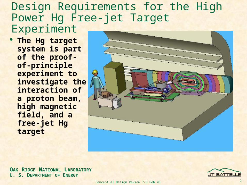
Design Requirements for the High Power Hg Free-jet Target Experiment
The Hg target system is part of the proof-of-principle experiment to investigate the interaction of a proton beam, high magnetic field, and a free-jet Hg target

3
OAK RIDGE NATIONAL LABORATORYU. S. DEPARTMENT OF ENERGY
Conceptual Design Review 7-8 Feb 05
The target system delivers a free (unconstrained) jet of Hg into a 1- atmosphere environment of air
1-cm diameter jet, delivered every 30 minutes
Full-beam interaction length is 30-cm
24 GeV, 1 MW proton beam, <20x1012 ppp
Beam line is 121-cm (47.6”) above tunnel floor
Up to 100 pulses for the CERN test, 500 pulses for systems tests
15 Tesla field
1-sec steady state jet during the magnet peak field (unresolved)
4
OAK RIDGE NATIONAL LABORATORYU. S. DEPARTMENT OF ENERGY
Conceptual Design Review 7-8 Feb 05
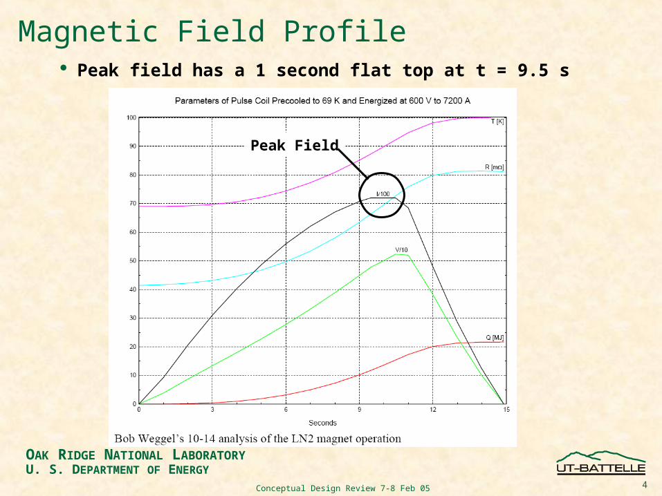
Magnetic Field Profile Peak field has a 1 second flat top at t = 9.5 s
Peak Field

5
OAK RIDGE NATIONAL LABORATORYU. S. DEPARTMENT OF ENERGY
Conceptual Design Review 7-8 Feb 05
Geometry
Jet to beam is 33 millirad (1.89°); jet to magnetic axis is 100 millirad (5.73°)
The PB crosses the jet centerline at Z=0, which is also at 15 T in the center of the solenoid
6
OAK RIDGE NATIONAL LABORATORYU. S. DEPARTMENT OF ENERGY
Conceptual Design Review 7-8 Feb 05
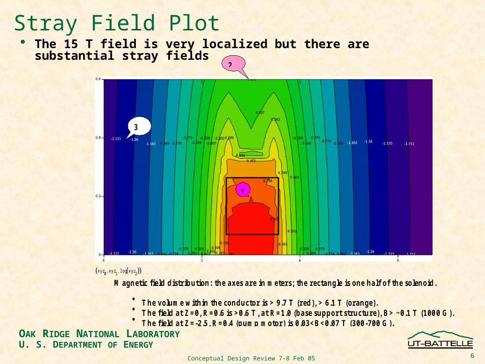
Stray Field Plot The 15 T field is very localized but there are substantial stray
fields
xyz0
xyz1
log xyz2
M a g n etic fie ld d is tr ib u tio n : th e a x es a re in m eters; th e rec ta n g le is o n e h a lf o f th e so len o id .
T h e v o lu m e w ith in th e co n d u cto r is > 9 .7 T (red ), > 6 .1 T (o ra n g e ). T h e fie ld a t Z = 0 , R = 0 .6 is > 0 .6 T , a t R = 1 .0 (b a se su p p o r t s tru c tu re ), B > ~ 0 .1 T (1 0 0 0 G ). T h e fie ld a t Z = -2 .5 , R = 0 .4 (p u m p m o to r ) is 0 .0 3 < B < 0 .0 7 T (3 0 0 -7 0 0 G ).
1
2
3
7
OAK RIDGE NATIONAL LABORATORYU. S. DEPARTMENT OF ENERGY
Conceptual Design Review 7-8 Feb 05
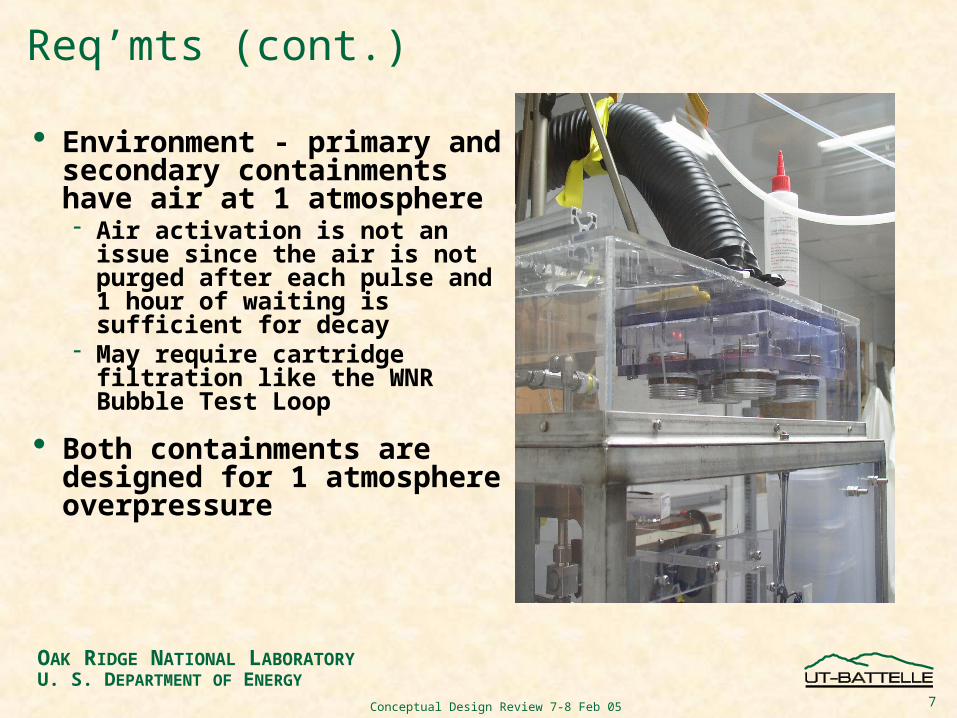
Req’mts (cont.)
Environment - primary and secondary containments have air at 1 atmosphere Air activation is not an issue
since the air is not purged after each pulse and 1 hour of waiting is sufficient for decay
May require cartridge filtration like the WNR Bubble Test Loop
Both containments are designed for 1 atmosphere overpressure
8
OAK RIDGE NATIONAL LABORATORYU. S. DEPARTMENT OF ENERGY
Conceptual Design Review 7-8 Feb 05
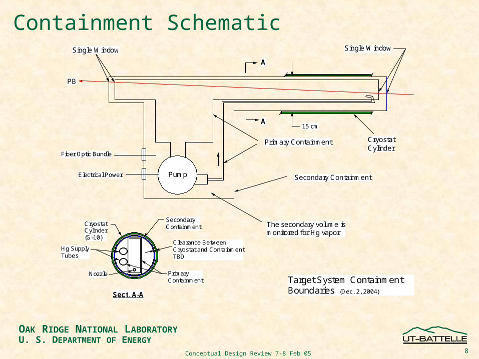
Containment SchematicSingle Window
Pump
Primary Containment
Secondary Containment
PB
The secondary volume ismonitored for Hg vapor
Single Window
CryostatCylinder(G-10)
SecondaryContainment
PrimaryContainment
Clearance BetweenCryostat and ContainmentTBD
Target System Containment Boundaries (Dec. 2, 2004)Sect. A-A
Hg SupplyTubes
Nozzle
15 cm
CryostatCylinder
A
A
Fiber Optic Bundle
Electrical Power
9
OAK RIDGE NATIONAL LABORATORYU. S. DEPARTMENT OF ENERGY
Conceptual Design Review 7-8 Feb 05
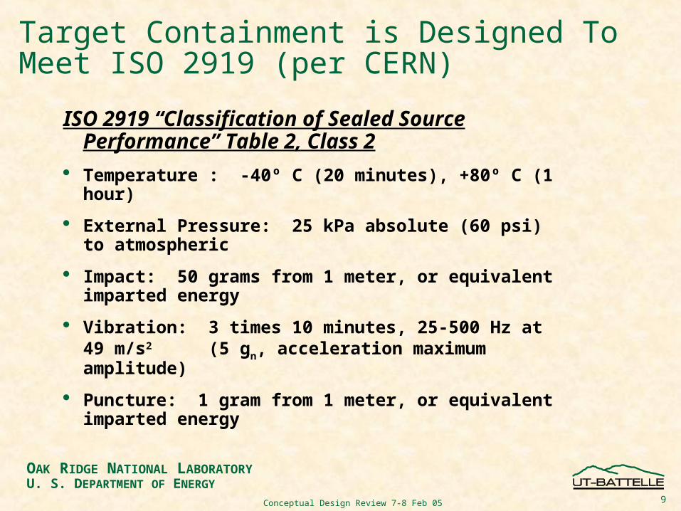
Target Containment is Designed To Meet ISO 2919 (per CERN)
ISO 2919 “Classification of Sealed Source Performance” Table 2, Class 2
Temperature : -40º C (20 minutes), +80º C (1 hour)
External Pressure: 25 kPa absolute (60 psi) to atmospheric
Impact: 50 grams from 1 meter, or equivalent imparted energy
Vibration: 3 times 10 minutes, 25-500 Hz at 49 m/s2
(5 gn, acceleration maximum amplitude)
Puncture: 1 gram from 1 meter, or equivalent imparted energy
10
OAK RIDGE NATIONAL LABORATORYU. S. DEPARTMENT OF ENERGY
Conceptual Design Review 7-8 Feb 05
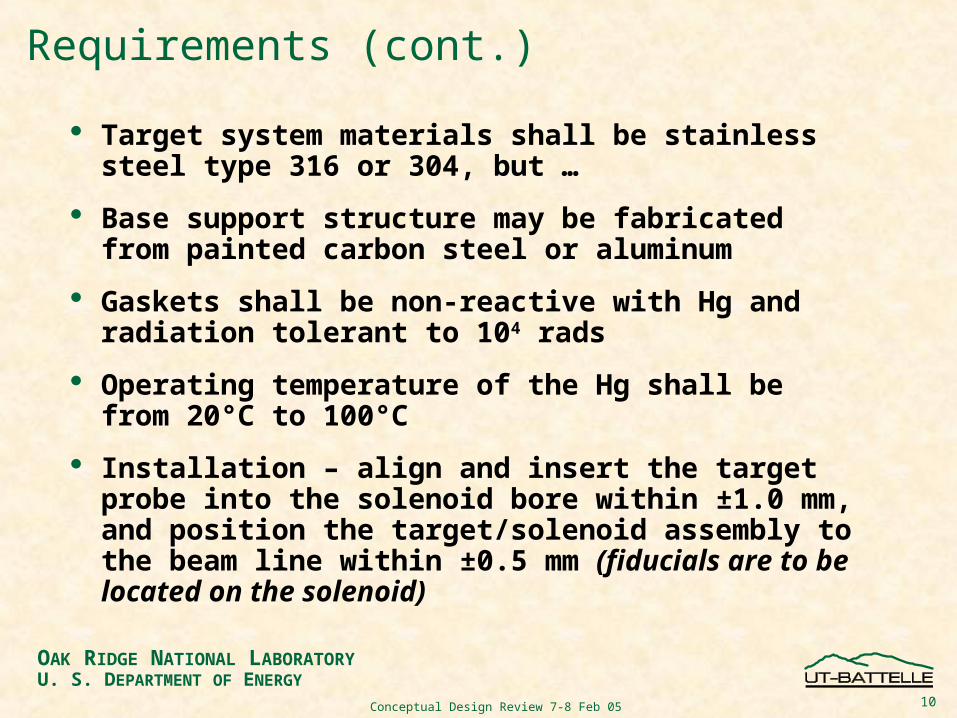
Requirements (cont.)
Target system materials shall be stainless steel type 316 or 304, but …
Base support structure may be fabricated from painted carbon steel or aluminum
Gaskets shall be non-reactive with Hg and radiation tolerant to 104 rads
Operating temperature of the Hg shall be from 20°C to 100°C
Installation – align and insert the target probe into the solenoid bore within ±1.0 mm, and position the target/solenoid assembly to the beam line within ±0.5 mm (fiducials are to be located on the solenoid)
11
OAK RIDGE NATIONAL LABORATORYU. S. DEPARTMENT OF ENERGY
Conceptual Design Review 7-8 Feb 05
Instrumentation
Hg vapor sensor to monitor the secondary containment atmosphere, with remote readout
Temperature sensor to monitor mercury in the sump tank, with remote readout
Position sensor on syringe to monitor Hg flow rate through cylinder
Viewing window(s) on the sump tank for visual observation during system tests

12
OAK RIDGE NATIONAL LABORATORYU. S. DEPARTMENT OF ENERGY
Conceptual Design Review 7-8 Feb 05
Other Req’mts
Maintenance/Handling - equipment is assembled hands on but maintained and operated with minimal contact by personnel
Design Life – designed for 10,000 start/stop cycles
Operating Cycle – up to 20 seconds of 1-cm jet every 30 minutes, up to the temperature limit of the Hg inventory
Filling/Draining Hg – vacuum pump or peristaltic pump
13
OAK RIDGE NATIONAL LABORATORYU. S. DEPARTMENT OF ENERGY
Conceptual Design Review 7-8 Feb 05
Interfaces Solenoid – the bore of the magnet positions the
target cassette
Proton Beam Windows – the upbeam and downbeam windows are mounted to the primary and secondary containments; Ti6Al4V alloy
Optical Diagnostics – 3 windows, lenses, prisms located on the primary containment, fiber optic cables, and cable penetrations into the secondary containment
Base Support Structure – base structure is shared with the solenoid
Facilities – ORNL (TTF) for equipment testing, MIT (?) for integrated system tests, and CERN for the experiment
14
OAK RIDGE NATIONAL LABORATORYU. S. DEPARTMENT OF ENERGY
Conceptual Design Review 7-8 Feb 05
Issues Yet To Be Addressed
Power supply/frequency for pump system at CERN
Electrical cable … who provides ~50 m of length
Labor for installation at MIT, CERN
What are the safety concerns … Ventilation Decommissioning/disposal
…

15
OAK RIDGE NATIONAL LABORATORYU. S. DEPARTMENT OF ENERGY
Conceptual Design Review 7-8 Feb 05
Project ScheduleBased on performing the experiment at CERN in early FY07
Hg Target System Design-CERNStart Date
Finish Date Jul Aug Sept Oct Nov Dec Jan Feb Mar Apr May Jun Jul Aug Sept Oct Nov Dec Jan Feb Mar Apr May Jun Jul Aug Sept Oct Nov Dec Jan
2004 2005 2006 2007
Jul Aug Sept Oct Nov Dec Jan Feb Mar Apr May Jun Jul Aug Sept Oct Nov Dec Jan Feb Mar Apr May Jun Jul Aug Sept Oct Nov Dec Jan
Solenoid/Cryostat MilestonesThis Schedule is Based on Testingat CERN in December, 2006Fabricate 5/31/04 2/27/05
Deliver/Install at MIT 2/28/05 3/27/05
Magnet System Test 3/28/05 5/29/05
Setup Target Equipment at MIT 2/20/06 3/12/06CERN Engineers and TechniciansIntegrated System Test at MIT 3/20/06 5/14/06
Install/Test Power Supply at CERN 6/5/06 7/31/06
Install Cryo System Equipment & Dewar 6/5/06 7/31/06
Ship Magnet & Target Systems To CERN 7/31/068/7/06
9/24/06
MITInstall Equipment in TT2A Tunnel 9/25/0610/2/06
10/22/06
Commission Test Equipment at CERN 10/30/06 11/29/06 CERN
Beam On Experiment 12/4/06 12/22/06
Decommission 12/25/06 1/21/07
Diamonds Indicate Estimated Travel
Hg Target System
1. System Design Princeton CERN ?1a. Engineering Coordination 7/5/04
11/15/043/28/059/5/053/7/05
1/25/07
AccApp05MIT ?1b. Establish Interfaces & Obtain Requirements
8/2/04 11/14/04
(BNL)1c. Neutronics Calcs (BNL) 8/2/04 8/31/04
1d. Develop Interface Dwgs 8/2/04 9/30/04
1e. Design Hg Flow Loop System
Title IFinal Design ReviewTitle I Design 11/15/04
4/25/051/30/05
Title IITitle II Design 2/14/05 4/24/05 Conceptual
Design Review1f. Develop Procurement Specification 2/28/05
2/7/054/1/05
1g. Design Optical Diagnostics (BNL) 10/1/042/14/05
2/6/054/24/05
(BNL)1h. Design Target Windows (BNL) 10/4/04 12/15/04
(BNL)
1i. Nozzle/Catcher Tests (Princeton) 12/27/04 2/6/05 (Princeton)1j. Procurement (Bid & Award) 5/2/05 7/24/05
1k. Fabrication 7/25/05 10/23/05
1l. Assembly and Systems Test 10/24/05 1/22/06
1m. Prepare/Ship Target Assembly to MIT 1/23/06 2/9/06 MIT1n. Install Target Equipment at MIT 2/20/06
2/27/063/12/06
2. Assist w/ Integrated Test at MIT 3/20/063/27/065/8/06
5/14/06
MITMIT3. Coordinate Design Effort with CERN 10/4/04 4/3/05
4. Develop Decommissioning and Disposition Plan
2/1/05 5/31/05
5. Develop Shipping & Installation Plan for MIT and CERN; Develop System Test Plan
6/1/05 9/30/05
CERN CERN6. Provide Support for the High-Power Tests at CERN
10/30/0611/13/0612/25/06
1/21/07(Rev. 6, Feb. 3, 2005)


![[p.T] Water Well Manual](https://img.pdfslide.us/doc/110x75/577d34871a28ab3a6b8e3c4c/pt-water-well-manual.jpg)