Embed Size (px)
DESCRIPTION
Baseplate
Citation preview

7/21/2019 Baseplates Options
http://slidepdf.com/reader/full/baseplates-options 1/4
Experience In Motion
M ark 3 Pre-Engineered Baseplates
Extend Pump and Seal Life at Reduced Cost
Flowserve offers five pre-engineered baseplate designs to
improve pump performance and reduce costs. Flowservepre-engineered baseplates extend pump and seal life by
reducing internal pump stress and vibrations. That is why
Flowserve recommends reinforced rigid baseplates.
Plus, customers who know the value of pre-engineered
and reinforced baseplates help avoid potential confusion
in specification interpretation, delays in shipments and
added costs.
Flowserve offers a broad range of metal and non-metallic,
grout and stilt mounted designs and standard options. This
provides broad flexibility in choosing the baseplate that best
meets application needs and operating budget.
Reducing Internal Stress and Vibration
Extends Life of Pump and Motor Packages
Pump users specify rigid baseplate designs to:
• Provide torsional lateral and longitudinal rigidity
• Improve vibration dampening
• Protect against transit damage
• Resist twisting during installation
• Maintain shaft alignment
• Reduce installation and shaft alignment time
• Reduce diaphragming or separation from grout
• Improve pump, motor and seal reliability
• Reduce total life cycle pump, motor and seal costs
Flowserve offers a family of five types
of pre-engineered baseplate designs to extend pump li fe and reduce costs.
Mark 3 Pre-Engineered Baseplate Designs
7/21/2019 Baseplates Options
http://slidepdf.com/reader/full/baseplates-options 2/4
2
Y =Standard N = Not available NR = Not recommended D =Needs design timeO =Optional NA =Not applicable C = Sloped catch basin with 25 mm (1 in) drain (option) S =Stilts for leveling
*Coplanar to 0.42 mm/m (0.005 in/ft)
ItemStandard Options
Type A Type B Type C Type D Type D Type ENo. Gp 1 & 2 Gp 3 with Rim
1Machined coplanar mounting surfaces to
O O O* O O O Y0.17 mm/m (0.002 in/ft) with 3.2 micron (125 µ in) finish
2 Added structural (cross member) support N N Y Y Y Y Y
3 Added torsional support with end caps NR Y Y D O O Y
4 Tapped holes for four (4) motor adjuster bolts O O NA O O O Y
5 Four (4) - SS transverse jack bolts - motor adjusters O O NA O O O Y
6 Sloped surface to an integral drain N N C N N N Y
7 Integral sloped drip rim around base N N N N N Y Y
8 102 mm (4 in) diameter grout holes - max. 762 mm (30 in) run to vent Y Y Y N Y Y Y
9 13 mm (1/2 in) vent holes at corner of each chamber NR O NR NA Y Y Y
10 Lower surface shaped to anchor in grout N N N NA Y Y Y11 Integral lifting eyes at four (4) corners O Y N O Y Y Y
12 Tapped leveling holes four (4) corners Y O Y S Y Y Y
13 Continuous seam weld construction NA Y NA O Y Y Y
14 Welded raised lip around grout hole(s) NR NR NA NA NR NR Y
15 Stilt mounting options with floor cups NR NA O Y D D NA
16 Spring mounted load designs NA NA O O D D NA
17 Catch basin (304SS or other materials) O O NA O O NR NA
18 Option for eight (8) total motor adjusters O O O O O O Y
19 Dimensions to ANSI B73.1 Y Y Y Y Y Y Y
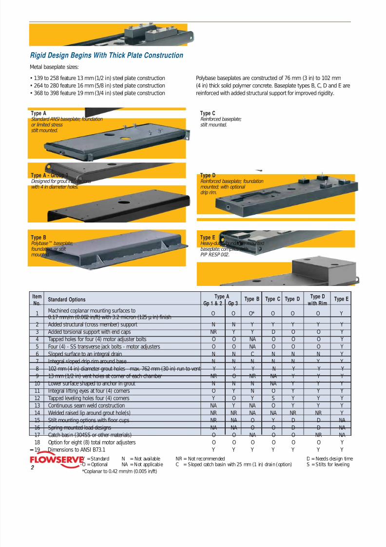
Rigid Design Begins With Thick Plate Construction
Metal baseplate sizes:
• 139 to 258 feature 13 mm (1/2 in) steel plate construction
• 264 to 280 feature 16 mm (5/8 in) steel plate construction
• 368 to 398 feature 19 mm (3/4 in) steel plate construction
Type AStandard ANSI baseplate; foundation or limited stressstilt mounted.
Type BPolybase™ baseplate;foundation or stiltmounted.
Type CReinforced baseplate; stilt mounted.
Type DReinforced baseplate; foundation mounted; with optional
drip rim.
Type EHeavy-duty, foundation mounted baseplate; complies withPIP RESP 002.
Type A - Group 3Designed for grout installations with 4 in diameter holes.
Polybase baseplates are constructed of 76 mm (3 in) to 102 mm
(4 in) thick solid polymer concrete. Baseplate types B, C, D and E are
reinforced with added structural support for improved rigidity.

7/21/2019 Baseplates Options
http://slidepdf.com/reader/full/baseplates-options 3/4
Polybase
• Low installed cost
• Superior vibration dampening
• Corrosion resistant
• Superior resistance to twisting or diaphragming• Standard catch basin and grout holes
• Inserts available for alternate equipment configuration
requirements
Polybase ™ and Polybloc ™
Solid Polymer Concrete Adjustment System
Baseplates are Fundamental to
Extending Pump Life
The test stand provided three corner support of the ungrouted
baseplates. The addition of weights on the unsupported fourth corner
caused baseplate distortion. This distortion resulted in measurable
shaft movement that can cause problems with field installations and
negatively affect pump reliability and life.
The twist test is a means of comparing rigid baseplate designs.
Correctly installed rigid baseplates should not experience these twist
effects. For more information about the results of baseplate testing,
contact your local Flowserve sales representative.
Polybloc – M otor
Mounting Block
• Corrosion resistant• Superior vibration dampening
• Full foot support (no overhang)
• Shown with optional bloc-lock
and fastener support
• Available for other pump and
motor or alternate equipment
applications
M ark 3 Pre-Engineered Baseplates
3
8-Point Adjuster • Allows precise motor
adjustment to reduce
alignment time
• Used with recessed
bloc-lock device
Type B – Polybase baseplate
Cast Iron0.125 sec.
Polymer Concrete0.125 sec.
© John F. Kane, Composites Institute, The Society of the Plastics Industry, Inc.
Baseplate Rigidity Test –Twist M ode
0.070 (1.78)
0.060 (1.52)
0.050 (1.27)
0.040 (1.02)
0.030 (0.08)
0.020 (0.51)
0.010 (0.25)
0.000 (0.00)
A
D
E
B
C
0 100 200(45) (91)
Load - lb (kg)
D e f l e c t i o n – i n c h ( m m )
Type A 0.022 in (0.56 mm)
Type B 0.004 in (0.01 mm)
Type C 0.003 in (0.08 mm)
Type D 0.016 in (0.41 mm)
Type E 0.005 in (0.13 mm)
Maximum ParallelShaft Deflection at
Applied Force
Vibration Damping of Polymer Concrete Versus Cast Iron

7/21/2019 Baseplates Options
http://slidepdf.com/reader/full/baseplates-options 4/4
flowserve.com
USA and CanadaFlowserve Corporation5215 North O’Connor Blvd.Suite 2300Irving, Texas 75039-5421 USA Telephone: 1 972 443 6500 Telefax: 1 972 443 6800
Europe, Middle East, AfricaFlowserve CorporationVia Rossini 90/9220033 Desio (Milan), Italy Telephone: 39 0362 6121 Telefax: 39 0362 303396
Latin America and CaribbeanFlowserve Corporation6840 Wynnwood LaneHouston, Texas 77008 USA Telephone: 1 713 803 4434 Telefax: 1 713 803 4497
Asia PacificFlowserve Pte. Ltd.200 Pandan Loop #06-03/04Pantech 21Singapore 128388 Telephone: 65 6775 3003 Telefax: 65 6779 4607
To find your local Flowserve representative:
For more information about Flowserve Corporation,
visit www.flowserve.com or call USA 1 800 728 PUMP (7867)
Bulletin PSS-10-13. 6 (E) Printed in USA. October 2006. © Flowserve Corporation