Embed Size (px)
Citation preview
21
Avionics Design for a Sub-Scale Fault- Tolerant Flight Control Test-Bed
Yu Gu1, Jason Gross2, Francis Barchesky3, Haiyang Chao4 and Marcello Napolitano5
West Virginia University USA
1. Introduction
The increasingly widespread use of Unmanned Aerial Vehicles (UAVs) has provided researchers with platforms for several different applications:
1. For carrying remote sensing or other scientific payloads. Highly publicized examples of such applications include the forest fire detection effort jointly conducted by NASA Ames research centre and the US Forest Service (Ambrosia et al., 2004), and the mission into the eye of hurricane Ophelia by an Aerosonde® UAV (Cione et al., 2008);
2. For evaluating different sensing and decision-making strategies as an autonomous vehicle. For examples, an obstacle and terrain avoidance experiment was performed at Brigham Young University to navigate a small UAV in the Goshen canyon (Griffiths et al., 2006); an autonomous formation flight experiment was performed at West Virginia University (WVU) with three turbine-powered UAVs (Gu et al., 2009);
3. As a sub-scale test bed to help solving known or potential issues facing full-scale manned aircraft. For example, a series of flight test experiments were performed at Rockwell Collins (Jourdan et al., 2010) with a sub-scale F-18 aircraft to control and recover the aircraft after wing damages. Another example is the X-48B blended wing body aircraft (Liebeck, 2004) jointly developed by Boeing and NASA to investigate new design concepts for future-generation transport aircraft.
Each of these applications poses different requirements on the design of the on-board avionic package. For example, the remote sensing platforms are often tele-operated by a ground pilot or controlled with a Commercial-off-the-Shelf (COTS) or open-source autopilot (Chao et al., 2009). The UAVs for sensing and decision making research often requires a higher level of customization for the avionic system. This can be achieved through either
1 Research Assistant Professor, Mechanical and Aerospace Engineering (MAE) Department, West Virginia University (WVU), Morgantown, WV 26506, Email: [email protected]; 2 Ph.D., MAE Dept., WVU, now at Jet Propulsion Laboratory, Pasadena, CA, Email: [email protected]; 3 M.S. Student, MAE Dept., WVU, Email: [email protected]; 4 Post-Doctoral Research Fellow, MAE Dept, WVU, Email: [email protected]; 5 Professor, MAE Dept., WVU, Email: [email protected].
www.intechopen.com
Recent Advances in Aircraft Technology
500
augmenting a COTS autopilot with a dedicated payload computer (Miller et al., 2005), or by having an entirely specialized avionics design (Evans et al., 2001). An alternative approach for smaller UAVs is to instrument an indoor testing environment (How et al., 2008) for measuring aircraft states so that a less complex avionic system could be used on-board the aircraft.
The avionic systems for sub-scale aircraft aimed at improving the safety of full-scale manned aircraft have a different set of design requirements. In addition to providing the standard measurement and control functions, the avionic system also needs to enable the simulation of different aircraft upset or failure conditions. Two general approaches have been used by different research groups. The first approach is to develop a highly realistic experimental environment in simulating a full-scale aircraft operation. For example, the Airborne Subscale Transport Aircraft Research Test bed (AirSTAR) program at NASA Langley research centre uses dynamically scaled airframe equipped with customized avionics for aviation safety research (Jordan et al., 2006) (Murch, 2008). During the research portion of the flight, the aircraft is controlled by a ground research pilot augmented by control algorithms running at a mobile ground station. An alternative approach is to develop a low-cost and expansible aircraft/avionic system for evaluating high-risk flight conditions (Christophersen et al., 2004).
Sub-scale aircraft have played critical complimentary roles to full-scale flight testing
programs due to lower risks, costs, and turn-around time. The objective of this chapter is to
discuss the specific avionics design requirements for supporting these experiments, and to
share the design experience and lessons learned at WVU over the last decade of flight
testing research. Specifically, in this chapter, detailed information for a WVU Generation-V
(Gen-V) avionic system design is presented, which is based on an innovative approach for
integrating both human and autonomous decision-making capabilities. Due to the high risk
and uncertain nature of experiments that explore adverse flight conditions, the avionics
itself is designed to reduce the risk of a Single Point of Failure (SPOF). This makes it possible
to achieve a reliable operation and seamless flight mode switching. The Gen-V avionics
design builds upon several earlier generations of WVU avionics that supported a variety of
research topics such as aircraft Parameter Identification (PID) (Phillips et al., 2010),
formation flight control (Gu et al., 2009), fault-tolerant flight control (Perhinschi et al., 2005),
and sensor fusion (Gross et al., 2011).
The rest of the chapter is organized as follows. Section 2 introduces the general design requirements for avionic systems used in fault-tolerant flight control research. Section 3 discusses the overall hardware design architecture and main sub-systems. Section 4 presents the control command signal distribution logic that enables the flexible and reliable transition among different flight modes. Section 5 presents the aircraft on-board software architecture and the real-time Global Positioning System/Inertial Navigation System (GPS/INS) sensor fusion algorithm. Ground and flight testing procedures and results for validating avionics functionalities are discussed in Section 6, and finally, Section 7 concludes the chapter.
2. Avionics design requirements for fault-tolerant flight control research
Fault tolerant flight control research pose special challenges for avionics design due to the complex nature of aviation accidents. The occurrence of aviation accidents can be attributed
www.intechopen.com
Avionics Design for a Sub-Scale Fault-Tolerant Flight Control Test-Bed
501
to many factors, such as weather conditions (e.g. icing or turbulence), pilot errors (e.g. disorientation or mis-judgment), air and ground traffic management errors, and a variety of sub-system failures (e.g. sensor, actuator, or propulsion system failures). Furthermore, the introduction of new technologies in aviation systems poses new threats to the safe operation of an aircraft. For example, modern fly-by-wire flight control systems are known to introduce new failure modes due to their dependence on computers and avionics (Yeh, 1998). Increased automation and flight deck complexity could also potentially degrade situational awareness, and require increased and highly aircraft-specific pilot training. These factors could potentially create new failure scenarios that have not yet been recognized as causes of accidents.
2.1 Research requirements
Due to the complexity of aviation accidents, a multi-functional avionics design is needed to support the fault-tolerant flight control research. The most important requirements for such a design include maintaining accurate and timely measurements of aircraft states, having the ability to emulate various aircraft upset or failure conditions, and providing a flexible interface between humans and automatic control systems. A breakdown of more specific avionics requirements for several aviation safety related research topics is summarized in Table 1.
Research Topic Specific Avionics Requirements
Aircraft modelling with manually injected manoeuvres
High quality sensor measurements; adequate update rate; monitoring of pilot activities; precise time-
alignment of all measured channels.
Aircraft modelling with an On-Board Excitation System (OBES)
Ability to automatically apply pre-specified waveform inputs to control effectors.
Failure emulation
Ability to inject and remove simulated aircraft sub-system failures, such as failures in a particular sensor,
actuator, or propulsion unit, or in the control command transmission link.
Fault-tolerant flight control (automatic)
Ability to command and reconfigure individual aircraft control effectors; having low system latency
and abundant computational resources.
Fault-tolerant flight control (pilot-in-the-loop)
Ability to augment the pilot command with automatic control algorithms.
Table 1. Design requirements for typical fault-tolerant flight control research topics.
2.2 Operational scenarios
A fundamental difference between operating a sub-scale and a full-scale aircraft is the absence of humans on-board. The removal of the physical presence of human pilots allows the testing of high-risk flight conditions and reduces the cost of the experiment. However, pilots are integral components of modern aviation systems and contributed to 29% of “fatal accidents involving commercial aircraft, world-wide, from 1950 thru 2009 for which a specific cause is known” (Planecrashinfo.com, 2011). Pilots are also the ultimate decision-makers on-board; therefore, the evaluations of their response under adverse situations and the detailed
www.intechopen.com
Recent Advances in Aircraft Technology
502
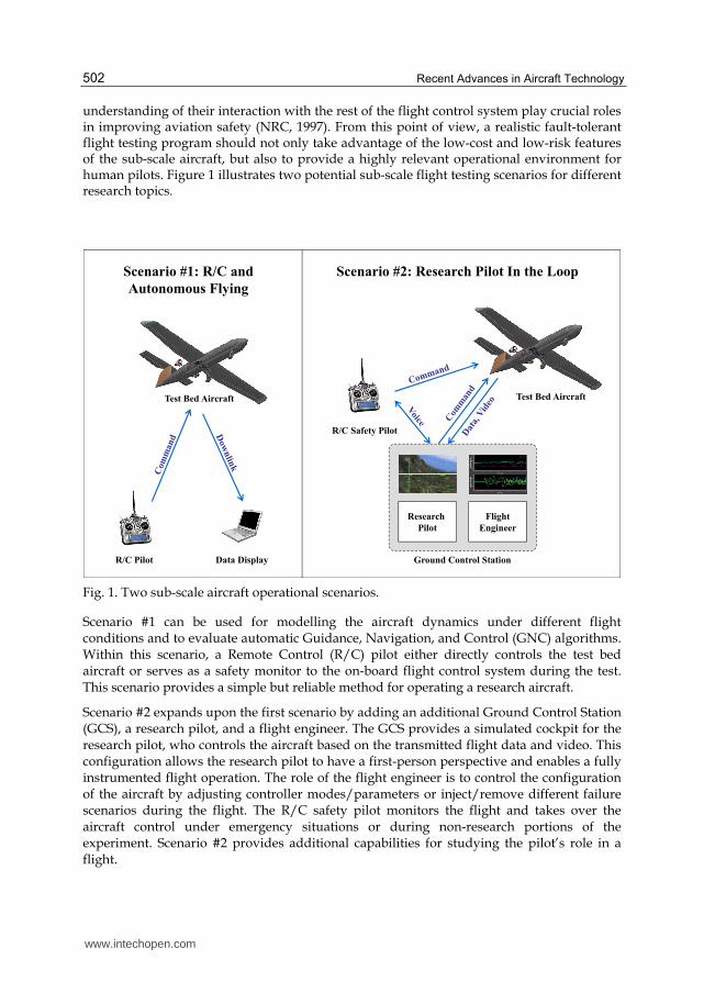
understanding of their interaction with the rest of the flight control system play crucial roles in improving aviation safety (NRC, 1997). From this point of view, a realistic fault-tolerant flight testing program should not only take advantage of the low-cost and low-risk features of the sub-scale aircraft, but also to provide a highly relevant operational environment for human pilots. Figure 1 illustrates two potential sub-scale flight testing scenarios for different research topics.
Research
Pilot
Flight
Engineer
Ground Control Station
R/C Safety Pilot
Test Bed Aircraft
Scenario #2: Research Pilot In the Loop
R/C Pilot
Scenario #1: R/C and
Autonomous Flying
Test Bed Aircraft
Data Display
Fig. 1. Two sub-scale aircraft operational scenarios.
Scenario #1 can be used for modelling the aircraft dynamics under different flight conditions and to evaluate automatic Guidance, Navigation, and Control (GNC) algorithms. Within this scenario, a Remote Control (R/C) pilot either directly controls the test bed aircraft or serves as a safety monitor to the on-board flight control system during the test. This scenario provides a simple but reliable method for operating a research aircraft.
Scenario #2 expands upon the first scenario by adding an additional Ground Control Station (GCS), a research pilot, and a flight engineer. The GCS provides a simulated cockpit for the research pilot, who controls the aircraft based on the transmitted flight data and video. This configuration allows the research pilot to have a first-person perspective and enables a fully instrumented flight operation. The role of the flight engineer is to control the configuration of the aircraft by adjusting controller modes/parameters or inject/remove different failure scenarios during the flight. The R/C safety pilot monitors the flight and takes over the aircraft control under emergency situations or during non-research portions of the experiment. Scenario #2 provides additional capabilities for studying the pilot’s role in a flight.
www.intechopen.com
Avionics Design for a Sub-Scale Fault-Tolerant Flight Control Test-Bed
503
2.3 Operational modes
To support the previously described research topics and the two operational scenarios, the following operational modes are typically required:
1. Manual Mode I – Direct Vision. An R/C safety pilot has full authority on all control channels in the basic stick-to-surface format. The pilot should always have the option of switching to this mode instantaneously under any conditions as long as the R/C link is available. This mode can be used for aircraft manual take-off and landing, manual PID manoeuvre injection, as well as emergency recovery from other operational modes;
2. Manual Mode II – Virtual Flight Display. A research pilot inside the ground control station has full authority on all control channels;
3. Fully Autonomous Mode. The on-board flight control system has full control of the aircraft, while the R/C pilot is only serving as an observer and safety backup;
4. Partially Autonomous Mode. A subset of the flight control channels is under autonomous control while other channels are still operated by the ground pilot;
5. Pilot-In-The-Loop Mode. The pilot command is supplied as input to a Stability Augmentation System (SAS) or a Control Augmentation System (CAS). This mode allows for studying the interaction between a human pilot and the automatic control system;
6. Failure Emulation Mode. A simulated failure condition is induced by the on-board computer to one or multiple control channels, while the remaining channels could be under manual, autonomous, or pilot-in-the-loop control;
7. Fail-Safe Modes. In the event that the ground pilot could not maintain manual control of the aircraft due to loss of an R/C link, the avionic system should explore redundant communication links and on-board autonomy to help in regaining the aircraft control or minimize the damage of a potential accident.
2.4 Hardware requirement
Due to the high-risk involved in testing various adverse flight conditions and the need for switching between multiple operational modes, the reliability requirements for the avionics hardware are significantly higher than that of a conventional autopilot system for a similar class of UAV. In other words, the avionic system needs to be fault-tolerant itself, and its design should minimize the risk of a SPOF condition. For example, redundant command and control links are needed in case the primary link is lost or interfered. Additionally, the safety pilot should be able to instantaneously switch back to the manual mode from any other operational mode, even in the event of main computer shutdown or power loss.
Additional requirements to the avionics hardware design typically include low-cost, low-weight, low-power consumption, low Electromagnetic Interference (EMI), configurable and expandable, and user-friendly.
3. WVU avionics architecture and main sub-systems
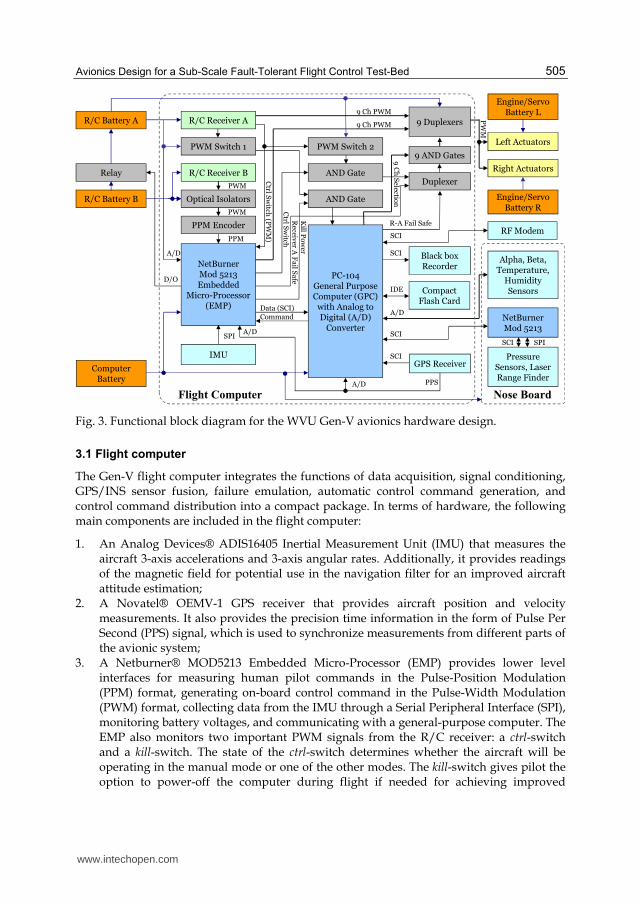
Based on design requirements outlined in the previous section, a Gen-V avionic system is being developed for a WVU ‘Phastball’ sub-scale research aircraft. The ‘Phastball’ aircraft has a 2.2 meter wingspan and a 2.2 meter total length. The typical take-off weight is 10.5 Kg with a 3.2 Kg payload capacity. The aircraft is propelled by two brushless electric ducted fans;
www.intechopen.com
Recent Advances in Aircraft Technology
504
each can provide up to 30 N of static thrust. The use of electric propulsion systems simplifies the flight operations and reduces vibrations on the airframe. Additionally, the low time constant associated with an electric ducted fan allows it to be used directly as an actuator or for simulating the dynamics of a slower jet engine. The cruise speed of the ‘Phastball’ aircraft is approximately 30 m/s. As a dedicated test-bed for fault-tolerant flight control research, the following nine channels can be independently controlled on the ‘Phastball’ aircraft: left/right elevators, left/right ailerons, left/right engines, rudder, nose gear, and longitudinal thrust vectoring.
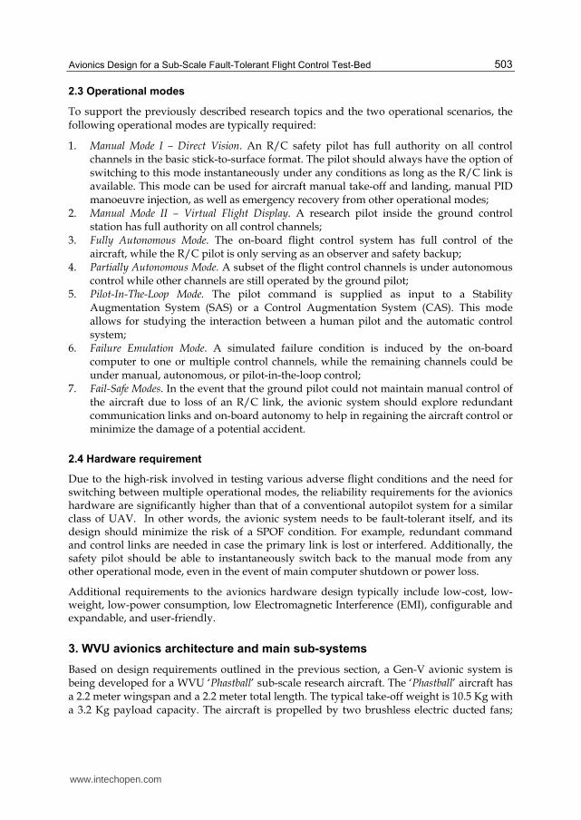
The avionic system features a flight computer, a nose sensor connection board, a control signal distribution board, a sensor suite, an R/C sub-system, a communication sub-system, a power sub-system, and a set of real-time software. It performs functions such as data acquisition, signal conditioning & distribution, GPS/INS sensor fusion, GNC, failure emulation, aircraft health monitoring, and failsafe functions. Figure 2 shows the ‘Phastball’ aircraft along with the main avionics hardware components.
Fig. 2. ‘Phastball’ aircraft and main avionics hardware components.
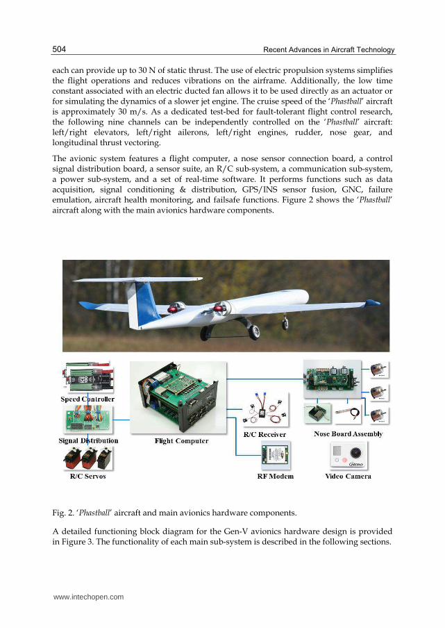
A detailed functioning block diagram for the Gen-V avionics hardware design is provided in Figure 3. The functionality of each main sub-system is described in the following sections.
www.intechopen.com
Avionics Design for a Sub-Scale Fault-Tolerant Flight Control Test-Bed
505
R/C Battery B
RF Modem
GPS Receiver
R/C Receiver B
IMU
Computer Battery
9 Duplexers
NetBurnerMod 5213Embedded
Micro-Processor (EMP)
PC-104General Purpose Computer (GPC)
with Analog to Digital (A/D)
Converter
Left Actuators
Engine/Servo Battery L
Black box Recorder
R/C Receiver A9 Ch PWM
SCI
SCI
SCI
SPI
A/D
R/C Battery A9 Ch PWM
Ctrl
Sw
itch(P
WM
)
Optical Isolators
PWM
9 AND Gates
Ctrl
Sw
itch
PW
M
Relay
Alpha, Beta, Temperature,
Humidity Sensors
A/D
D/O
AND Gate
PWM Switch 2
9C
hS
election
Data (SCI)Command
PWM Switch 1
Kill
Po
wer
Right Actuators
Engine/Servo Battery R
Duplexer
Receiv
erA
Fa
ilS
afe
R-A Fail Safe
NetBurnerMod 5213
Pressure Sensors, Laser Range Finder
SCI SPI
Flight Computer Nose Board
SCI
Compact Flash Card
IDE
PPSA/D
A/D
PPM Encoder
PPM
PWM
AND Gate
Fig. 3. Functional block diagram for the WVU Gen-V avionics hardware design.
3.1 Flight computer
The Gen-V flight computer integrates the functions of data acquisition, signal conditioning, GPS/INS sensor fusion, failure emulation, automatic control command generation, and control command distribution into a compact package. In terms of hardware, the following main components are included in the flight computer:
1. An Analog Devices® ADIS16405 Inertial Measurement Unit (IMU) that measures the aircraft 3-axis accelerations and 3-axis angular rates. Additionally, it provides readings of the magnetic field for potential use in the navigation filter for an improved aircraft attitude estimation;
2. A Novatel® OEMV-1 GPS receiver that provides aircraft position and velocity measurements. It also provides the precision time information in the form of Pulse Per Second (PPS) signal, which is used to synchronize measurements from different parts of the avionic system;
3. A Netburner® MOD5213 Embedded Micro-Processor (EMP) provides lower level interfaces for measuring human pilot commands in the Pulse-Position Modulation (PPM) format, generating on-board control command in the Pulse-Width Modulation (PWM) format, collecting data from the IMU through a Serial Peripheral Interface (SPI), monitoring battery voltages, and communicating with a general-purpose computer. The EMP also monitors two important PWM signals from the R/C receiver: a ctrl-switch and a kill-switch. The state of the ctrl-switch determines whether the aircraft will be operating in the manual mode or one of the other modes. The kill-switch gives pilot the option to power-off the computer during flight if needed for achieving improved
www.intechopen.com

Recent Advances in Aircraft Technology
506
ground-control reliability during the safety critical (such as landing) portion of the flight;
4. Two COTS PWM switches provide independent monitoring of the critical ctrl-switch
and kill-switch;
5. An 800 MHz PC-104+ form factor General-Purpose Computer (GPC) hosts the aircraft
on-board software. It also provides additional 16 Analog to Digital Conversion (ADC)
channels and 6 Serial Communication Interfaces (SCI) for communicating with the GPS
receiver, the EMP, the nose board assembly, and the ground control station;
6. A logic network that distributes control command from both human pilots and
automatic control systems to individual actuators based on the selected operational
mode of the avionic system;
7. A compact flash memory card storing the operating system, the on-board software, and
the collected flight data;
8. A black-box data recorder stores a real-time stream of sensory data, control command,
and the avionics health information during the flight.
A detailed description of the aircraft control command generation and distribution is
provided in Section 4.
3.2 Sensor suite
In addition to the IMU and the GPS receiver embedded inside the Gen-V flight computer,
the ‘Phastball’ aircraft is also equipped with three P3America® MP1545A inductive
potentiometers for measuring aircraft flow angles, two Sensor Technics® pressure sensors
for measuring the dynamic and static pressures, a Measurement Specialities® HTM2500
temperature and relative humidity sensor, and an Opti-Logic® RS400 laser range finder.
Additionally, the pilot input, engine operating parameters, and R/C receiver status are also
recorded in flight. The aircraft attitude angles are provided with a real-time GPS/INS sensor
fusion algorithm, which will be described in Section 5.
3.3 Power system
To reduce SPOF, the arrangement of battery power has been carefully determined. A total of
five battery packs are used to power different components of the avionic system.
Specifically, an R/C battery-A is connected to R/C receiver-A and an logic network for
control command distribution; an R/C battery-B is used to power receiver-B; the computer
battery powers EMP, GPC, and all sensing, communication, and data storage devices;
engine/servo batteries L and R power the left and right side engines and R/C servos
independently. With this configuration, the failure of any given battery would not cause a
total loss of aircraft control during the flight. Specifically, if EMP detects that receiver-A
battery is low, it activates a relay to tie up R/C batteries A and B so that there would be
enough power for a safe landing. If the computer battery loses its power, the logic network
powered by receiver-A battery automatically switches to the manual mode and gives the
R/C pilot full control authority. If one of the engine/servo batteries fails, the pilot still has
independent control for half of the aircraft actuators (propulsion and control surfaces) and
would be able to perform a controlled landing.
www.intechopen.com

Avionics Design for a Sub-Scale Fault-Tolerant Flight Control Test-Bed
507
3.4 Ground control station
The GCS computer collects the aircraft downlink telemetry data, the nose camera video, the weather information, the GPS time/position measurements, the voice communication, as well as inputs from the R/C pilot, the research pilot, and the flight engineer. The data stream is accessible by the research pilot, the flight engineer, and field researchers in near real-time through a local network. For the research pilot station, three displays are provided including an X-Plane® based synthetic-vision primary flight display overlapped with a Heads-Up Display (HUD) that shows the flight parameters and mission constraints, a flight instrumentation display with a navigation window, and a screen showing the real-time flight video transmitted from the aircraft nose camera. The research pilot flies the aircraft through a set of joystick, rudder pedals, and throttle handles. The flight engineer has access to all available flight data and can change the aircraft operational mode or inject/remove failures with or without notifying the research pilot. Figure 4 shows the layout of the GCS vehicle.
Weather Sensor
GPS Antenna
RF Modem Antenna
Synthetic Vision Display w/ HUD
Flight Instrument
Nose Camera Video
Flight
Engineer
Station
Fig. 4. The exterior (left) and interior (right) of the ground control station vehicle.
The duplex communications between the ground control station and the test bed aircraft is provided with a pair of 900 MHz Freewave ® Radio Frequency (RF) modems. The downlink communication packet contains information about aircraft states and avionics health conditions. The uplink packet integrates both the research pilot control commands and the flight engineer configuration commands. Both the uplink and downlink data are transmitted at a rate of 50Hz.
4. Control command signal distribution
One of the important features of the WVU Gen-V avionics design is its ability to provide a flexible and reliable interface between control commands generated by humans and automatic controllers. This capability is achieved through the interaction of different hardware components and software functions.
www.intechopen.com
Recent Advances in Aircraft Technology
508
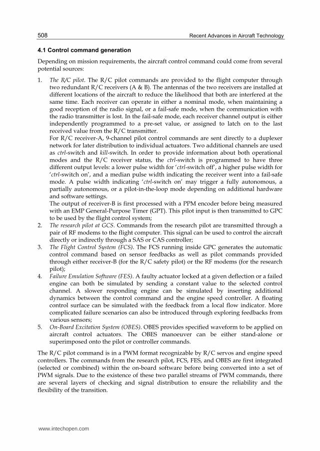
4.1 Control command generation
Depending on mission requirements, the aircraft control command could come from several potential sources:
1. The R/C pilot. The R/C pilot commands are provided to the flight computer through two redundant R/C receivers (A & B). The antennas of the two receivers are installed at different locations of the aircraft to reduce the likelihood that both are interfered at the same time. Each receiver can operate in either a nominal mode, when maintaining a good reception of the radio signal, or a fail-safe mode, when the communication with the radio transmitter is lost. In the fail-safe mode, each receiver channel output is either independently programmed to a pre-set value, or assigned to latch on to the last received value from the R/C transmitter. For R/C receiver-A, 9-channel pilot control commands are sent directly to a duplexer network for later distribution to individual actuators. Two additional channels are used as ctrl-switch and kill-switch. In order to provide information about both operational modes and the R/C receiver status, the ctrl-switch is programmed to have three different output levels: a lower pulse width for ‘ctrl-switch off’, a higher pulse width for ‘ctrl-switch on’, and a median pulse width indicating the receiver went into a fail-safe mode. A pulse width indicating ‘ctrl-switch on’ may trigger a fully autonomous, a partially autonomous, or a pilot-in-the-loop mode depending on additional hardware and software settings. The output of receiver-B is first processed with a PPM encoder before being measured with an EMP General-Purpose Timer (GPT). This pilot input is then transmitted to GPC to be used by the flight control system;
2. The research pilot at GCS. Commands from the research pilot are transmitted through a pair of RF modems to the flight computer. This signal can be used to control the aircraft directly or indirectly through a SAS or CAS controller;
3. The Flight Control System (FCS). The FCS running inside GPC generates the automatic control command based on sensor feedbacks as well as pilot commands provided through either receiver-B (for the R/C safety pilot) or the RF modems (for the research pilot);
4. Failure Emulation Software (FES). A faulty actuator locked at a given deflection or a failed engine can both be simulated by sending a constant value to the selected control channel. A slower responding engine can be simulated by inserting additional dynamics between the control command and the engine speed controller. A floating control surface can be simulated with the feedback from a local flow indicator. More complicated failure scenarios can also be introduced through exploring feedbacks from various sensors;
5. On-Board Excitation System (OBES). OBES provides specified waveform to be applied on aircraft control actuators. The OBES manoeuver can be either stand-alone or superimposed onto the pilot or controller commands.
The R/C pilot command is in a PWM format recognizable by R/C servos and engine speed controllers. The commands from the research pilot, FCS, FES, and OBES are first integrated (selected or combined) within the on-board software before being converted into a set of PWM signals. Due to the existence of these two parallel streams of PWM commands, there are several layers of checking and signal distribution to ensure the reliability and the flexibility of the transition.
www.intechopen.com
Avionics Design for a Sub-Scale Fault-Tolerant Flight Control Test-Bed
509
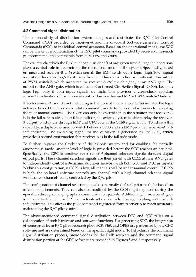
4.2 Command signal distribution
The command signal distribution system manages and distributes the R/C Pilot Control Command (PCC) provided by receiver-A and the on-board Software-generated Control Commands (SCC) to individual control actuators. Based on the operational mode, the SCC can be one of or a combination of the R/C pilot commands provided by receiver-B, research pilot command, and commands from FCS, FES, and OBES.
The ctrl-switch, which the R/C pilot can turn on/off at any given time during the operation,
plays a central role in determining the operational mode of the system. Specifically, based
on measured receiver-B ctrl-switch signal, the EMP sends out a logic (high/low) signal
indicating the status (on/off) of the ctrl-switch. This status indicator meets with the output
of PWM switch-2, which measures the receiver-A ctrl-switch signal, at an AND gate. The
output of the AND gate, which is called as Confirmed Ctrl Switch Signal (CCSS), becomes
logic high only if both input signals are high. This provides a cross-check avoiding
accidental activation of the on-board control due to either an EMP or PWM switch-2 failure.
If both receiver-A and B are functioning in the normal mode, a low CCSS initiates the logic
network to feed the receiver-A pilot command directly to the control actuators for enabling
the pilot manual control. The CCSS can only be overridden in the situation that receiver-A
is in the fail-safe mode. Under this condition, the avionic system is able to relay the receiver-
B output to actuators through EMP and GPC even if the CCSS signal is low. To achieve this
capability, a duplexer is used to switch between CCSS and an EMP provided receiver-A fail-
safe indicator. The switching signal for the duplexer is generated by the GPC, which
provides a second confirmation that receiver-A is in the fail-safe mode.
To further improve the flexibility of the avionic system and for enabling the partially
autonomous mode, another level of logic is provided before the SCC reaches an actuator.
Specifically, the GPC is sending out a set of 9-channel selection signals through digital
output ports. These channel selection signals are then joined with CCSS at nine AND gates
to independently control a 9-channel duplexer network with both SCC and PCC as inputs.
Within this configuration, if CCSS is low, all channels will be under manual control. If CCSS
is high, the on-board software controls any channel with a high channel selection signal
with the rest channels being controlled by the R/C pilot.
The configuration of channel selection signals is normally defined prior to flight based on
mission requirements. They can also be modified by the GCS flight engineer during the
operation through changing uplink communication packets. Additionally, if receiver-A goes
into the fail-safe mode the GPC will activate all channel selection signals along with the fail-
safe indicator. This allows the pilot command registered from receiver-B to reach actuators,
maintaining the R/C pilot control.
The above-mentioned command signal distribution between PCC and SCC relies on a
collaboration of both hardware and software functions. For generating SCC, the integration
of commands from R/C pilot, research pilot, FCS, FES, and OBES are performed by the GPC
software and are determined based on the specific flight mode. To help clarify the command
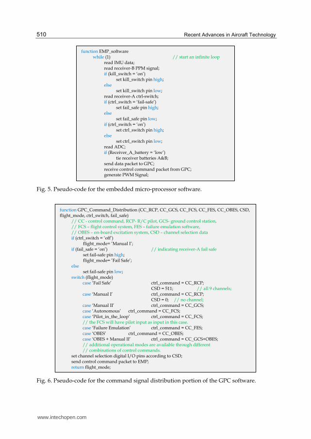
signal distribution process, pseudo-codes for the EMP software and the command signal
distribution portion of the GPC software are provided in Figures 5 and 6 respectively.
www.intechopen.com
Recent Advances in Aircraft Technology
510
Fig. 5. Pseudo-code for the embedded micro-processor software.
Fig. 6. Pseudo-code for the command signal distribution portion of the GPC software.
function GPC_Command_Distribution (CC_RCP, CC_GCS, CC_FCS, CC_FES, CC_OBES, CSD, flight_mode, ctrl_switch, fail_safe) // CC - control command, RCP- R/C pilot, GCS- ground control station, // FCS – flight control system, FES – failure emulation software, // OBES – on-board excitation system, CSD – channel selection data
if (ctrl_switch = ‘off’) flight_mode= ’Manual I’; if (fail_safe = ‘on’) // indicating receiver-A fail safe set fail-safe pin high; flight_mode= ’Fail Safe’; else set fail-safe pin low; switch (flight_mode)
case ‘Fail Safe’ ctrl_command = CC_RCP; CSD = 511; // all 9 channels; case ‘Manual I’ ctrl_command = CC_RCP; CSD = 0; // no channel; case ‘Manual II’ ctrl_command = CC_GCS; case ‘Autonomous’ ctrl_command = CC_FCS; case ‘Pilot_in_the_loop’ ctrl_command = CC_FCS; // the FCS will have pilot input as input in this case. case ‘Failure Emulation’ ctrl_command = CC_FES; case ‘OBES’ ctrl_command = CC_OBES; case ‘OBES + Manual II’ ctrl_command = CC_GCS+OBES; // additional operational modes are available through different // combinations of control commands.
set channel selection digital I/O pins according to CSD; send control command packet to EMP; return flight_mode;
function EMP_software while (1) // start an infinite loop
read IMU data; read receiver-B PPM signal; if (kill_switch = ‘on’) set kill_switch pin high; else set kill_switch pin low; read receiver-A ctrl-switch; if (ctrl_switch = ‘fail-safe’) set fail_safe pin high; else set fail_safe pin low; if (ctrl_switch = ‘on’) set ctrl_switch pin high; else set ctrl_switch pin low; read ADC; if (Receiver_A_battery = ‘low’) tie receiver batteries A&B; send data packet to GPC; receive control command packet from GPC; generate PWM Signal;
www.intechopen.com

Avionics Design for a Sub-Scale Fault-Tolerant Flight Control Test-Bed
511
5. On-board software
5.1 Operating systems
The use of a general-purpose computer within the avionics design facilitates the use of
abundant COTS and open source software products. The on-board Operating System (OS)
for GPC is the Linux kernel 2.6.9 patched with Real-Time Application Interface (RTAI) 3.2.
An RTAI target was implemented so that Simulink® schemes can be compiled into real-time
executable files using the Matlab Real Time Workshop®. The auto-coding capability allows
for a rapid integration and testing of algorithms developed by independent researchers.
The NetBurner® MOD5213 EMP uses a μC/OS real-time operating system. The main functionality of the EMP software was outlined in Figure 5.
5.2 GPC software
The GPC software has a modular structure that is first implemented in Simulink® before
being compiled into real-time executable files. Each module is either a combination of
existing Simulink blocks or a custom S-function written in C language. The modular
structure allows for parallel development and debugging, quick and easy configuration for
different mission requirements, and intuitive visual interpolation of the software.
Additionally, without any modification the same software module can be first simulated in
the Simulink® environment before being tested in flight. The main modules of the GPC
software and their connectivity are shown in Figure 7.
A/D Conversion
Sensory Data Conditioning, Calibration,
& Organization
Receive GPS Data
GPS/INS Sensor Fusion
Outer-Loop Guidance Law
Inner Loop Control Law
Command Calibration
Control Channel Selection
Receive GCS Command
Receive EMP Data
Data Logging / Send to GCS
CommandSignal
Distribution
Data Acquisition
Receive Nose Board Data
Flight Control
Failure Emulation
On-Board Excitation
Send Command to EMP
Data
Command
Main Data Bus R/C Pilot Command
Fig. 7. GPC on-board software architecture.
www.intechopen.com
Recent Advances in Aircraft Technology
512
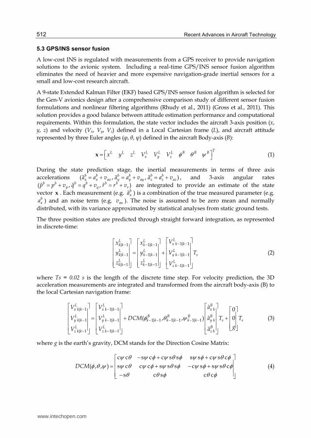
5.3 GPS/INS sensor fusion
A low-cost INS is regulated with measurements from a GPS receiver to provide navigation solutions to the avionic system. Including a real-time GPS/INS sensor fusion algorithm eliminates the need of heavier and more expensive navigation-grade inertial sensors for a small and low-cost research aircraft.
A 9-state Extended Kalman Filter (EKF) based GPS/INS sensor fusion algorithm is selected for
the Gen-V avionics design after a comprehensive comparison study of different sensor fusion
formulations and nonlinear filtering algorithms (Rhudy et al., 2011) (Gross et al., 2011). This
solution provides a good balance between attitude estimation performance and computational
requirements. Within this formulation, the state vector includes the aircraft 3-axis position (x,
y, z) and velocity (Vx, Vy, Vz) defined in a Local Cartesian frame (L), and aircraft attitude
represented by three Euler angles (φ, θ, ψ) defined in the aircraft Body-axis (B):
TL L L L L L B B B
x y zx y z V V V x (1)
During the state prediction stage, the inertial measurements in terms of three axis
accelerations ( , , )b b b b b bx x ax y y ay z z aza a v a a v a a v , and 3-axis angular rates
( , , )b b b b b bp q rp p v q q v r r v are integrated to provide an estimate of the state
vector x . Each measurement (e.g. bxa ) is a combination of the true measured parameter (e.g.
bxa ) and an noise term (e.g. axv ). The noise is assumed to be zero mean and normally
distributed, with its variance approximated by statistical analyses from static ground tests.
The three position states are predicted through straight forward integration, as represented in discrete-time:
1| 1| 1 1| 1
| 1 1| 1 1| 1
| 1 1| 1 1| 1
LL Lx k kk k k k
L L Lk k k k y k k s
L L Lk k k k z k k
Vx x
y y V T
z z V
(2)
where Ts = 0.02 s is the length of the discrete time step. For velocity prediction, the 3D acceleration measurements are integrated and transformed from the aircraft body-axis (B) to the local Cartesian navigation frame:
| 1 1| 1
| 1 1| 1 1| 1 1| 1 1| 1
| 1 1| 1
0
( , , ) 0
L L Bx k k x k k x k
L L B B B By k k y k k k k k k k k y k s s
L L Bz k k z k k z k
V V a
V V DCM a T T
gV V a
(3)
where g is the earth’s gravity, DCM stands for the Direction Cosine Matrix:
c c s c c s s s s c s c
( , , ) s c c c s s s c s s s c
s c s c c
DCM
(4)
www.intechopen.com
Avionics Design for a Sub-Scale Fault-Tolerant Flight Control Test-Bed
513
where ‘s’ and ‘c’ are abbreviated sine and cosine functions respectively.
The aircraft Euler angles are predicted with the 3-axis angular rate measurements:
1| 1 1| 1 1| 1 1| 1| 1 1| 1
| 1 1| 1 1| 1 1| 1
| 1 1| 11| 1 1|
sin tan cos tan
cos sin
( sin cos
B B B B B B BB Bk k k k k k k k k k kk k k k
B B B B B Bk k k k k k k k k k
B BB B Bk k k kk k k k k k
p q r
q r
q r
1 1| 1)sec
s
B Bk k
T
(5)
The nine predicted state variables are then regulated by the GPS position and velocity measurements during the measurement update process with a simple observation equation:
L L L L L Lk k k x k k y k k z
TL L L L L Lx k x k Vx y k y k Vy z k z k Vz
x x v y y v z z v
V V v V V v V V v
z
(6)
The solution of the GPS/INS sensor fusion problem follows the classis EKF approach as outlined in (Simon, 2006). The filter tuning is performed through the selection of the process noise covariance matrix Q and the measurement noise covariance matrix R. Specifically, the process noise is approximated by the sensor-level noise present on the IMU measurement.
2 2 2 2 2 2 2([0,0,0, , , , , , ])ax ay az p q rv v v v v v sQ diag T (7)
where the first three zeros indicate that no uncertainty is associated with Equation (2). Similarly, the variance of the GPS measurement noise calculated with a ground static test is used for providing the R matrix:
2 2 2 2 2 2([ , , , , , ])x y z Vx Vy Vzv v v v v vR diag (8)
250 300 350 400 450 500 550-70
-60
-50
-40
-30
-20
-10
0
10
20
30
Time (s)
Deg
rees
Roll Estimation Vs. Vertical Gyro
Vertical Gyro
EKF Estimate
250 300 350 400 450 500 550-30
-20
-10
0
10
20
30
Time (s)
Deg
rees
Pitch Estimation Vs. Vertical Gyro
Vertical Gyro
EKF Estimate
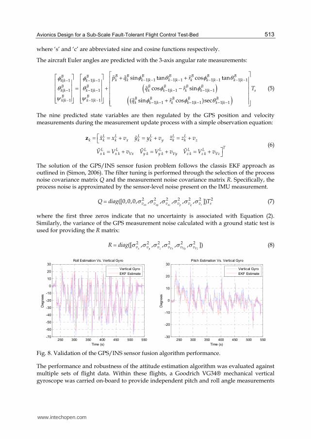
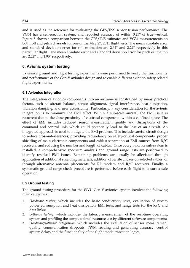
Fig. 8. Validation of the GPS/INS sensor fusion algorithm performance.
The performance and robustness of the attitude estimation algorithm was evaluated against multiple sets of flight data. Within these flights, a Goodrich VG34® mechanical vertical gyroscope was carried on-board to provide independent pitch and roll angle measurements
www.intechopen.com
Recent Advances in Aircraft Technology
514
and is used as the reference for evaluating the GPS/INS sensor fusion performance. The VG34 has a self-erection system, and reported accuracy of within 0.25° of true vertical. Figure 8 shows a comparison between the GPS/INS estimates and VG34 measurements on both roll and pitch channels for one of the May 27, 2011 flight tests. The mean absolute error and standard deviation error for roll estimation are 2.64° and 2.29° respectively in this particular flight. The mean absolute error and standard deviation error for pitch estimation are 2.22° and 1.93° respectively.
6. Avionic system testing
Extensive ground and flight testing experiments were performed to verify the functionality
and performance of the Gen-V avionics design and to enable different aviation safety related
flight experiments.
6.1 Avionics integration
The integration of avionics components into an airframe is constrained by many practical
factors, such as aircraft balance, sensor alignment, signal interference, heat-dissipation,
vibration damping, and user accessibility. Particularly, a key consideration for the avionic
integration is to minimize the EMI effect. Within a sub-scale aircraft, the EMI issue is
recurrent due to the close proximity of electrical components within a confined space. The
effect of EMI includes reduced sensor measurement quality and disruptions of the
command and control link, which could potentially lead to the loss of an aircraft. An
integrated approach is used to mitigate the EMI problem. This include careful circuit design
to reduce cross-interferences; providing redundancy on safety-critical components; proper
shielding of main electronic components and cables; separation of EMI sources from R/C
receivers; and reducing the number and length of cables. Once every avionics sub-system is
installed, a comprehensive spectrum analysis and ground range tests are performed to
identify residual EMI issues. Remaining problems can usually be alleviated through
application of additional shielding materials, addition of ferrite chokes on selected cables, or
through alternative antenna placements for RF modem and R/C receivers. Finally, a
systematic ground range check procedure is performed before each flight to ensure a safe
operation.
6.2 Ground testing
The ground testing procedure for the WVU Gen-V avionics system involves the following main categories:
1. Hardware testing, which includes the basic conductivity tests, evaluation of system power consumption and heat dissipation, EMI tests, and range tests for the R/C and data links;
2. Software testing, which includes the latency measurement of the real-time operating system and profiling the computational resource use by different software components;
3. Hardware/software integration, which includes the evaluation of sensor measurement quality, communication dropouts, PWM reading and generating accuracy, control system delay, and the functionality of the flight mode transition logics;
www.intechopen.com
Avionics Design for a Sub-Scale Fault-Tolerant Flight Control Test-Bed
515
4. Reliability testing, which includes a number of duration tests under simulated dynamic operating environments;
5. Calibration, which includes the calibration of individual sensors, PWM reading and generating processes, individual control actuators, and pilot input devices such as R/C transmitter and the research pilot control station;
6. Modelling, this includes the development of mathematical models for the test-bed aircraft, actuators, propulsion systems, and sensors, as well as the identification of model parameters;
7. Simulation, which includes model-based simulation for initial validation of mission-specific research algorithms, and hardware-in-the-loop simulation for evaluating the integration between hardware and software sub-systems.
A flight test is considered after all related ground tests are performed.
6.3 Flight testing
Flight testing provides the final validation of the aircraft and its flight control system. However, it is also well known that experimental flight testing program, either with a full-scale or a sub-scale aircraft, is associated with substantial risks. A general strategy for flight risk mitigation focus on three steps:
1. Prevent the aircraft from entering an adverse flight condition; 2. Timely identification of the problem when an emergency situation develops; 3. Recover the aircraft or minimize its damage during the accident.
An adverse flight condition could be caused by improper/inadequate planning, pilot error, atmospheric condition, and aircraft sub-system (e.g. mechanical, electrical, power, control, and communication) failures. Quite often, an aviation accident has multiple inter-connected contributing factors (Boeing, 2009).
It is worth noting that the general objective of a fault-tolerant flight control research
program with a sub-scale aircraft is usually to facilitate the development of the fault
prevention, identification, and recovery methods for a full-scale manned aircraft. During
flight experiments, the aircraft is often commanded to enter deliberately-planned adverse
conditions, while minimizing other flight-associated potential risks. This high level of
uncertainty, with both expected and unexpected failure contributing factors, provides
valuable experiences and insights for understanding aviation accidents and the unique
opportunity to practice and refine risk mitigation approaches.
6.3.1 Risk mitigation and flight testing protocol
Two effective approaches for improving the operational safety of a sub-scale flight testing program are incremental testing and the standardization of flight protocols. The incremental flight testing method utilizes a ‘divide and conquer’ approach to build-up individual sub-system capabilities and allows them to mature over a series of increasingly complex experiments. Each step should be a logic extension of previous steps, but should also be large enough to ensure a timely completion of the project. For example, an experiment to study the aircraft dynamics at high angle of attack flight conditions could be built upon the following key steps:
www.intechopen.com
Recent Advances in Aircraft Technology
516
1. R/C flights for evaluating aircraft handling quality, stall characteristics, and payload capacity;
2. Data acquisition flights to evaluate avionics measurement quality and GPS/INS sensor fusion algorithm performance;
3. Closed-loop flights with a set of inner-loop control laws stabilizing the aircraft at the trim flight condition;
4. Closed-loop flights around the trim condition with OBES injection; 5. Closed-loop flights at high angle of attack conditions with OBES injection.
The standardization of flight testing protocols reduces human error both before and during the flight. It allows a systematic planning, resource allocation, testing, and inspection during the flight preparation. During the flight, having a standard procedure and flight pattern reduces pilot stress and improve the consistency among flights. Additionally, having an emergency handling procedure reduces the pilot reaction time and avoids making arbitrary decisions under adverse flight conditions. The flight testing protocol builds upon years of flight testing experience and provides a media to store and apply lessons learned from past mistakes.
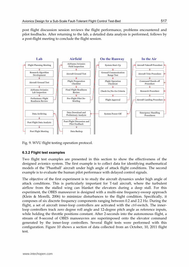
A flow chart for the flight testing operation procedure developed at WVU is shown in Figure 9. A flight test session starts with a flight planning meeting in the lab discussing mission objectives, test methods, and personal responsibilities. A preliminary flight readiness review is normally performed a day before the flight date, following successful efforts in research algorithm development, ground test, and aircraft inspection.
At the airfield, another round of aircraft inspection and ground tests are performed to
ensure that all aircraft sub-systems are operational after ground transportation. This is
enforced with a flight preparation check-list, which covers airframe, avionics, R/C system,
power system, firmware, research software, communication system, and the ground station.
Additionally, the aircraft weight and balance are checked before the first flight of each
aircraft. A final flight readiness review is then performed after the checklist is completed.
Finally, a pre-flight pilot de-briefing discusses the flight procedures, research manoeuvres,
and potential risks of this particular flight.
Once the aircraft is positioned at its starting position on the runway, the propulsion, R/C,
and avionics systems are powered following an aircraft start-up procedure. A series of range
tests are then performed to evaluate the R/C and data link range. A flight operation
checklist is filled to verify the general functionality of the aircraft, such as control surface
deflections, propulsion system condition, and R/C system fail-safe settings. A set of ‘go/no-
go’ criteria, which includes wind-speed, wind-direction, communication range, and ground
crew readiness, are then evaluated before a final approval of the flight by the flight director.
The flight operation itself follows a set of pre-defined take-off, trim, command hands-off, research, and landing procedures. In case of an emergency, such as a single engine failure, both engine failure, controller failure, actuator failure, aircraft upset condition, or changing weather condition, a set of specific emergency handling procedures are followed to abort the flight and recover the aircraft.
After landing and powering off the aircraft, flight data are downloaded and analysed in the field to provide an initial assessment of data quality and determine any potential issues. A
www.intechopen.com
Avionics Design for a Sub-Scale Fault-Tolerant Flight Control Test-Bed
517
post flight discussion session reviews the flight performance, problems encountered and pilot feedbacks. After returning to the lab, a detailed data analysis is performed, follows by a post-flight meeting to conclude the flight session.
Aircraft Ground Test
Lab
Flight Planning Meeting
Airfield
Research Algorithm Development
Airframe/Avionics Lab Inspection
Post Flight Data Analysis
Data Archiving
Post Flight Meeting
Preliminary Flight Readiness Review
Airframe/Avionics Field Inspection
Aircraft Ground Test
Flight Preparation Checklist
Final Flight Readiness Review
Pre-Flight Pilot De-Briefing
On the Runway
System Start-Up
Ground Communication Range Test
Flight Operation CheckList
Check Go/No-Go Criteria
Data Download and Preliminary Analysis
Post-Flight Discussion and Pilot Feedback
Data Backup
In the Air
Aircraft Takeoff Procedure
Aircraft Trim Procedure
Command Hands-off Procedure
Research Procedure
Aircraft Landing Procedure
Emergency Handling Procedures
System Power-Off
Flight Approval
Fig. 9. WVU flight testing operation protocol.
6.3.2 Flight test examples
Two flight test examples are presented in this section to show the effectiveness of the designed avionics system. The first example is to collect data for identifying mathematical models of the ‘Phastball’ aircraft under high angle of attack flight conditions. The second example is to evaluate the human pilot performace with delayed control signals.
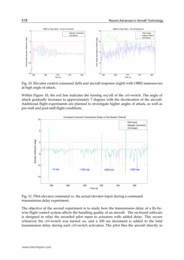
The objective of the first experiment is to study the aircraft dynamics under high angle of attack conditions. This is particularly important for T-tail aircraft, where the turbulent airflow from the stalled wing can blanket the elevators during a deep stall. For this experiment, the OBES manoeuver is designed with a multi-sine frequency-sweep approach (Klein & Morelli, 2006) to minimize disturbances to the flight condition. Specifically, it composes of six discrete frequency components ranging between 0.2 and 2.2 Hz. During the flight, a set of aircraft inner-loop controllers are activated with the ctrl-switch. The inner-loop controllers track zero degree roll angle and 12-degree pitch angle as reference inputs, while holding the throttle positions constant. After 2-seconds into the autonomous flight, a stream of 8-second of OBES manoeuvres are superimposed onto the elevator command generated by the inner-loop controllers. Several flight tests were performed with this configuration. Figure 10 shows a section of data collected from an October, 10, 2011 flight test.
www.intechopen.com
Recent Advances in Aircraft Technology
518
360 365 370 375 380-15
-10
-5
0
5OBES at High Alpha - Control Command
Time (s)
Com
ma
nde
d E
levato
r D
efl
ecti
on
(de
g)
Elevator Command
Ctrl-Switch
360 365 370 375 380-5
0
5
10
15OBES at High Alpha - Aircraft Response
Time (s)
Pitch
An
gle
and
Ang
le o
f A
tta
ck
(deg
)
Pitch Angle
Angle of Attack
Ctrl-Switch
Fig. 10. Elevator control command (left) and aircraft response (right) with OBES manoeuvres at high angle of attack.
Within Figure 10, the red line indicates the turning on/off of the ctrl-switch. The angle of attack gradually increases to approximately 7 degrees with the deceleration of the aircraft. Additional flight experiments are planned to investigate higher angles of attack, as well as pre-stall and post-stall flight conditions.
260 280 300 320 340 360
-15
-10
-5
0
5
10Increased Command Transmission Delay on the Elevator Channel
Time (s)
Ele
va
tor
Defl
ect
ion (
deg
)
Pilot Input
Elevator Command
Ctrl-Switch
+300 ms+200 ms+100 ms+0 ms
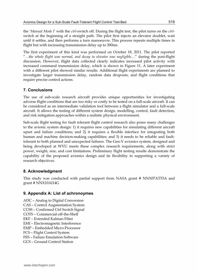
Fig. 11. Pilot elevator command vs. the actual elevator input during a command transmission delay experiment.
The objective of the second experiment is to study how the transmission delay of a fly-by-wire flight control system affects the handling quality of an aircraft. The on-board software is designed to relay the recorded pilot input to actuators with added delay. This occurs whenever the ctrl-switch was turned on, and a 100 ms increment is added to the total transmission delay during each ctrl-switch activation. The pilot flies the aircraft directly in
www.intechopen.com
Avionics Design for a Sub-Scale Fault-Tolerant Flight Control Test-Bed
519
the ‘Manual Mode I’ with the ctrl-switch off. During the flight test, the pilot turns on the ctrl-switch at the beginning of a straight path. The pilot first injects an elevator doublet, wait until it settles, and then performs a turn manoeuvre. This process repeats multiple times in flight but with increasing transmission delay up to 300ms.
The first experiment of this kind was performed on October 18, 2011. The pilot reported “…the whole flight was normal, and decay in elevator was negligible…” during the post-flight discussion. However, flight data collected clearly indicates increased pilot activity with increased command transmission delay, which is shown in Figure 11. A later experiment with a different pilot showed similar results. Additional flight experiments are planned to investigate larger transmission delay, random data dropouts, and flight conditions that require precise control actions.
7. Conclusions
The use of sub-scale research aircraft provides unique opportunities for investigating adverse flight conditions that are too risky or costly to be tested on a full-scale aircraft. It can be considered as an intermediate validation tool between a flight simulator and a full-scale aircraft. It allows the testing of different system design, modelling, control, fault detection, and risk mitigation approaches within a realistic physical environment.
Sub-scale flight testing for fault tolerant flight control research also poses many challenges
to the avionic system design: 1) it requires new capabilities for simulating different aircraft
upset and failure conditions; and 2) it requires a flexible interface for integrating both
human and machine decision-making capabilities; and 3) it needs to be reliable and fault-
tolerant to both planned and unexpected failures. The Gen-V avionics system, designed and
being developed at WVU meets these complex research requirements, along with strict
power, weight, size, and cost limitations. Preliminary flight testing results demonstrate the
capability of the proposed avionics design and its flexibility in supporting a variety of
research objectives.
8. Acknowledgment
This study was conducted with partial support from NASA grant # NNX07AT53A and grant # NNX10AI14G
9. Appendix A: List of achronoymes
ADC – Analog to Digital Conversion CAS – Control Augmentation System CCSS – Confirmed Ctrl Switch Signal COTS – Commercial-off-the-Shelf EKF – Extended Kalman Filter EMI – Electromagnetic Interference EMP – Embedded Micro-Processor FCS – Flight Control System FES – Failure Emulation Software GCS – Ground Control Station
www.intechopen.com
Recent Advances in Aircraft Technology
520
GNC – Guidance, Navigation, Control GPC – General-Purpose Computer GPS – Global Positioning System GPT – General-Purpose Timer HUD – Heads-Up Display IMU – Inertial Measurement Unit INS – Inertial Navigation System OBES – On-Board Excitation System OS – Operating System PCC – Pilot Control Command PID – Parameter Identification PPM – Pulse-Position Modulation PWM – Pulse-Width Modulation R/C – Remote Control RF – Radio Frequency RTAI – Real-Time Application Interface SAS – Stability Augmentation System SCC – Software-generated Control Commands SCI – Serial Communication Interfaces SPI – Serial Peripheral Interface SPOF – Single Point of Failure UAV – Unmanned Aerial Vehicle WVU – West Virginia University
10. References
Ambrosia, V.G.; Brass, J.A.; Greenfield, P. & Wegener, S. (2004). Collaborative Efforts in R&D and Applications of Imaging Wildfires, US Forest Service. Available: http://geo.arc.nasa.gov/sge/WRAP/projects/docs/RS2004_PAPER.PDF.
Boeing Commercial Airplanes, (2009) Statistical Summary of Commercial Jet Airplane Accidents, World Wide Operations, 1959-2008, Seattle, WA, Available: http://www.boeing.com/news/techissues.
Chao, H.Y.; Jensen, A.M.; Han, Y.; Chen, Y.Q. & McKee, M. (2009). AggieAir: Towards Low-cost Cooperative Multispectral Remote Sensing Using Small Unmanned Aircraft Systems, Chapter, Advances in Geoscience and Remote Sensing, Gary Jedlovec, Ed.Vukovar,Croatia:IN-TECH,pp.467–490.
Christophersen, H.B.; Pickell, W.J.; Koller, A.A.; Kannan, S.K & Johnson, E.N. (2004). Small Adaptive Flight Control Systems for UAVs using FPGA/DSP Technology, Proceedings of the AIAA “Unmanned Unlimited” Technical Conference, Workshop, and Exhibit, Chicago, IL, September, 2004.
Cione, J.J.; Uhlhorn, E. W.; Cascella, G.; Majumdar, S. J.; Sisko, C.; Carrasco, N.; Powell, M. D.; Bale, P.; Holland, G.; Turlington, P.; Fowler, D.; Landsea, C. W. & Yuhas, C. L. (2008). The First Successful Unmanned Aerial System (UAS) Mission into a Tropical Cyclone (Ophelia 2005), 12th Conference on IOAS-AOLS, New Orleans, LA, January 2008.
Evans, J.; Inalhan, G.; Jang J.S.; Teo, R. & Tomlin, C.J. (2001). DragonFly: a Versatile UAV Platform for the Advancement of Aircraft Navigation and Control, Digital Avionics
www.intechopen.com
Avionics Design for a Sub-Scale Fault-Tolerant Flight Control Test-Bed
521
Systems, DASC. The 20th Conference, vol.1, pp.1C3/1-1C3/12, Daytona Beach, FL, October, 2001.
Griffiths, S.; Saunders, J.; Curtis, A.; Barber, B.; McLain, T. & Beard, R. (2006). Maximizing Miniature Aerial Vehicles, IEEE Robotics & Automation Magazine, vol.13, no.3, pp. 34-43, Sept. 2006.
Gross, J.; Gu, Y.; Rhudy, M.; Gururajan, S. & Napolitano, M.R. (2011). Flight Test Evaluation of Sensor Fusion Algorithms for Attitude Estimation, IEEE Transactions on Aerospace and Electronic Systems, In Press, June, 2011.
Gu, Y.; Campa, G.; Seanor, B.; Gururajan, S. & Napolitano, M.R. (2009). Autonomous Formation Flight – Design and Experiments, Chapter, Aerial Vehicles, ISBN 978-953-7619-41-1, I-Tech Education and Publishing, Austria, EU, Chapter 12, pp. 233-256.
How, J.P.; Bethke, B.; Frank, A.; Dale, D. & Vian, J. (2008). Real-Time Indoor Autonomous Vehicle Test Environment, IEEE Control Systems Magzine, vol.28, no.2, pp.51-64, April, 2008.
Jordan, T. L.; Foster, J. V.; Bailey, R. M.; & Belcastro, C. M. (2006). AirSTAR: A UAV Platform for Flight Dynamics and Control System Testing, 25th AIAA Aerodynamic Measurement Technology and Ground Testing Conference, San Francisco, CA, June, 2006.
Jourdan, D.B.; Piedmonte,M.D.; Gavrilets,V. & Vos,D.W. (2010). Enhancing UAV Survivability Through Damage Tolerant Control, AIAA Guidnace Navigation and Control Conference, Toronto, Ontario, Canada, August, 2010.
Klein, V. & Morelli, E.A. (2006). Aircraft System Identification – Theory and Practice, AIAA Education Series, AIAA, Reston, VA.
Liebeck, R.H. (2004). Design of the Blended Wing Body Subsonic Transport, Journal of Aircraft, pp. 10-25, Vol. 41, No. 1, January–February, 2004.
Miller, J.A.; Minear, P.D.; Niessner, A.F.; DeLullo, A.M.; Geiger, B.R.; Long, L.L. & Horn, J.F. (2005). Intelligent Unmanned Air Vehicle Flight Systems, Infotec@AIAA, Arlington, Virginia, September, 2005.
Murch, A. M. (2008). A Flight Control System Architecture for the NASA AirSTAR Flight Test Infrastructure, AIAA Guidance, Navigation, and Control Conference, Honolulu, HI, August, 2008.
NRC (National Research Council) (1997). Aviation Safety And Pilot Control: Under-standing and Preventing Unfavorable Pilot-Vehicle Interactions, National Academy Press.
Perhinschi, M.; Napolitano, M.R.; Campa, G.; Seanor, B.; Gururajan, S. & Gu, Y. (2005). Design and Flight Testing of Intelligent Flight Control Laws for the WVU YF-22 Model Aircraft, AIAA Guidance, Navigation, and Control Conference, San Francisco, California, August, 2005.
Phillips, K.; Gururajan, S.; Campa, G.; Seanor, B.; Gu, Y. & Napolitano, M.R. (2010). Nonlinear Aircraft Model Identification and Validation for a Fault-Tolerant Flight Control System, AIAA Atmospheric Flight Mechanics Conference, Toronto, Ontario, Canada, August 2010.
Planecrashinfo.com (2011). Causes of Fatal Accidents by Decade, Avaliable: http://planecrashinfo.com/cause.htm.
Rhudy, M.; Gu, Y.; Gross, J. & Napolitano, M. R. (2011). Sensitivity Analysis of EKF and UKF in GPS/INS Sensor Fusion, AIAA Guidance, Navigation, and Control Conference, Portland, OR, August, 2011.
www.intechopen.com

Recent Advances in Aircraft Technology
522
Simon, D. (2006). Optimal State Estimation: Kalman, H-Innity, and Nonlinear Approaches. Wiley & Sons, 1. edition.
Yeh, Y.C. (1998). Design Considerations in Boeing 777 Fly-By-Wire Computers, Third IEEE International High-Assurance Systems Engineering Symposium, Washington, DC, November, 1998.
www.intechopen.com
Recent Advances in Aircraft TechnologyEdited by Dr. Ramesh Agarwal
ISBN 978-953-51-0150-5Hard cover, 544 pagesPublisher InTechPublished online 24, February, 2012Published in print edition February, 2012
InTech EuropeUniversity Campus STeP Ri Slavka Krautzeka 83/A 51000 Rijeka, Croatia Phone: +385 (51) 770 447 Fax: +385 (51) 686 166www.intechopen.com
InTech ChinaUnit 405, Office Block, Hotel Equatorial Shanghai No.65, Yan An Road (West), Shanghai, 200040, China
Phone: +86-21-62489820 Fax: +86-21-62489821
The book describes the state of the art and latest advancements in technologies for various areas of aircraftsystems. In particular it covers wide variety of topics in aircraft structures and advanced materials, controlsystems, electrical systems, inspection and maintenance, avionics and radar and some miscellaneous topicssuch as green aviation. The authors are leading experts in their fields. Both the researchers and the studentsshould find the material useful in their work.
How to referenceIn order to correctly reference this scholarly work, feel free to copy and paste the following:
Yu Gu, Jason Gross, Francis Barchesky, Haiyang Chao and Marcello Napolitano (2012). Avionics Design for aSub-Scale Fault- Tolerant Flight Control Test-Bed, Recent Advances in Aircraft Technology, Dr. RameshAgarwal (Ed.), ISBN: 978-953-51-0150-5, InTech, Available from: http://www.intechopen.com/books/recent-advances-in-aircraft-technology/avionic-design-for-a-sub-scale-fault-tolerant-flight-control-test-bed-