Embed Size (px)
Citation preview
AUTONOMOUS IMAGE BASED LOCALISATION FOR A MARTIAN AEROBOT
Dave Barnes1, Phil Summers1, Andy Shaw1, Roger Ward2, Mark Woods2, Malcolm Evans2, Gerhard Paar3, andMark Sims4
1Dept. of Computer Science, University of Wales, Aberystwyth, SY23 3DB, UK. [email protected] (Space & Defence) Ltd., Bristol, BS4 5SS, UK. [email protected]
3Institute of Digital Image Processing, Joanneum Research, Graz, A-8010, Austria. [email protected] Research Centre, Dept. of Physics and Astronomy, University of Leicester, LE1 7RH, UK. [email protected]
ABSTRACT
Balloon based aerobots have much to offer ESA’s fu-ture planetary exploration programmes, e.g. high reso-lution mapping, landing site selection, rover guidance,data relay, sample site selection, payload delivery, andatmospheric measurement and meteorology. Aerobotscould be used in a variety of configurations from un-controlled free-flying to tethered rover operation, and areable to perform a range of important tasks which otherexploration vehicles cannot. In many ways they providea missing ‘piece’ of the exploration ‘jigsaw’, acting asa bridge between the capabilities of in-situ landers androvers and non-contact orbiters. Technically, a Lighterthan Air (LTA) aerobot concept is attractive because itis low risk, low-cost, efficient, and much less complexthan Heavier than Air (HTA) vehicles such as fixed winggliders, and crucially, much of the required technology‘building blocks’ currently exist. Smart imaging and lo-calisation is a key enabling technology for remote aero-bots. Given the current lack of comprehensive localisa-tion and communications systems, it is important that aer-obots are equipped with the ability to determine their lo-cation, with respect to a planet’s surface. The availabilityof a variety of terrain feature extraction, point tracking,and image compression algorithms, means that a self-reliant system is now achievable. We are currently devel-oping a demonstrator imaging and localisation package(ILP) for a Martian balloon1. This ILP system incorpo-rates a unique combination of image based relative andabsolute localisation techniques. We are demonstratingour ILP using both simulation and a real laboratory basedmodel aerobot. The availability of both simulated andreal aerobot data thus providing a comprehensive test andevaluation framework for the ILP functionality.
1This work is being funded under the ESA Contract No.17400/03/NL/CH. The authors would like to thank G. Visentin (ESAD/TOS), Head of Automation and Robotics Section, and C. Hansen(IMT-CTM), Contracts Officer, for their collaboration with this work.
Key words: Aerobot; autonomous; localisation; simula-tion; DEM generation.
1. BACKGROUND
Whilst much attention has been given to the use of lan-ders and rovers for planetary exploration, most notablythe NASA JPL Sojourner rover (1), and the current Marsexploration rovers Spirit and Opportunity (2), the use offlying robots, or aerobots, for planetary exploration rep-resents a highly innovative concept. Whilst lander androver technology is clearly competent at facilitating use-ful science, their application is terrain limited. Rovers arecapable of travelling relatively small distances and muchof a planet’s terrain is impassable to small wheeled vehi-cles, aerobots in comparison have no such limitations.
For those planets and moons that support an atmosphere,flying robots are likely to provide a practical solu-tion to the problem of extended atmospheric meteorol-ogy, planetary surface coverage for terrain mapping, andsurface/sub-surface composition surveying. Not onlycould such devices be used for suborbital mapping ofterrain regions, but they could be used to transport anddeploy science packages or even microrovers at differ-ent geographically separate land sites. If tethered, thenthey could provide valuable navigation information forthe control of the attached surface rover.
The challenge of flying a planetary aerobot encompassesmobility control and autonomous navigation in a con-stantly changing 3D environment. Inter-planetary dis-tances prohibit the real-time communication of exter-nal meteorological and internal robot state data whichwould allow human remote control from Earth. An aer-obot’s long term endurance and ultimate survival can beachieved only if sophisticated autonomous flight controland navigation methods are employed. It is to addressthese challenges that our research is dedicated (3).

Aerobots drifting in the vagaries of a Martian wind acrossits often rugged terrain, will need to be autonomous, com-municating with an orbiter as chance permits. With lim-ited resources of memory and power, the main problemwill be economic storage and use of acquired images. Allunnecessary imagery will need to be suppressed. Posi-tional data will need to be provided to any scientific pack-age carried. Although other means of navigation could beprovided, using already available imagery would be themost economic. Thus our study is designed to investi-gate localisation to the required accuracy (commensuratewith the imagery requirements), economic use of mem-ory to store the vast quantity of images, and the problemof predicting the next communication window with an or-biter, so that the best use of storage can be made to meetthe mission targets without loss of any important infor-mation. The main outputs of the mission are to be, a 3Ddigital elevation model of the surface (DEM), and imagesof the surface at various resolutions.
This project has been to study and design an Imaging andLocalisation Package (ILP) for a Martian balloon. Thepackage allowing optimal acquisition of images to re-construct accurate models of the surface of the exploredplanet, and accurate localisation of the balloon with re-spect to the Martian surface. The ILP by means of aer-obot mounted cameras and computer vision techniquescan:
• acquire and store images of the surface at variousresolutions,
• construct and update a 3D model (DEM) of the sur-face,
• constantly estimate the position (latitude, longitudeand altitude) of the aerobot as well as its motion withrespect to the surface, and
• decide on the base of the communications budget,of the morphology of the surface and of the infor-mation content of the images (i.e. ‘image richness’),which images at which resolution/compression needto be transmitted to Earth.
2. ILP SYSTEM OVERVIEW
Fig. 1 outlines the basic components and processing flowof our proposed ILP system. The ILP system is designedto control, acquire and process images from a single cam-era suspended from the balloon gondola. There are anumber of technical challenges posed by individual taskssuch as assessing image scientific content or richness, andpredicting uplink windows (4), and additionally there isthe general problem of performing these tasks in a con-strained real-time environment. Fig. 2 shows availablecycle times versus speed at a number of heights (alti-tude in metres) for a camera with a 70◦ field of view(FOV), and maintained image overlap of 70%. When
these figures are examined within the context of a lab-oratory based demonstrator, available cycle time is re-duced dramatically due to the very small altitude distancebetween the ILP balloon system and a laboratory mockterrain (typically 2.5m). Significant algorithm optimisa-tion is required to meet these real-time demands, togetherwith a very slow ILP balloon ground velocity, and fastimage data processing.
To combat these real-time constraints we have con-structed an ILP balloon gondola, see Fig. 3, which con-tains an on-board mobile PC, hard-disk drive, wirelessethernet for ground station PC communication, laserbased altimeter, digital camera and battery power supply.Image data processing on-board negates the bandwidthand time delay problems associated with first transmit-ting images to a remote ground based PC prior to dataprocessing. Key to our method of aerobot localisation isthe generation of a DEM of the terrain below. However,as only one camera is flown on our gondola to limit massetc., then additional data is required by our DEM gen-eration algorithm. This data is provided by our gondolaaltimeter. To emulate the effects of the Martian wind onour ILP gondola and helium filled balloon, we have de-signed and built two pairs of micro-propulsion units. Theunits within each pair are counter rotated. One pair pro-vides vertical thrust, and these are attached to the gon-dola, whilst the second pair, which provide horizontalthrust, are attached to the balloon envelope about the totalsystem centre of mass. This arrangement provides maxi-mum camera stability when the balloon is in motion, andprevents any undesirable gondola ‘pendulum’ like mo-tion. The small micro-propulsion unit propellers possesbi-directional pitch variable blades. These allow very lowand precise balloon ground speed control to be achieved(< 2cm/sec). Each micro-propulsion unit is connectedto the on-board PC via servo drive interface electronics.The total gondola mass is ≈ 2kg and neutral buoyancyis achieved with a helium inflated envelope of diameter≈ 1.8m. The gondola camera has been calibrated usingthe same rig that was used to calibrate the Beagle 2 MarsLander PAW stereo cameras (5). This has allowed numer-ous camera image mosaics of the ESTEC Planetary TestBed (PTB) terrain to be captured for ILP demonstrationpurposes, see Fig. 5.
An important aspect of our ILP system is that it incorpo-rates a unique combination of image based relative andabsolute localisation techniques. Information about po-sition and pointing of an aerobot platform is necessaryto spatio-temporally assign each measurement from anyscience instrument or other sensor on the aerial vehi-cle. Here we define absolute localisation as being un-dertaken when, for example, a DEM generated by an aer-obot ILP is spatially matched to that of a global referenceDEM. Such a DEM could come from an orbiter’s data,e.g. MGS MOLA, or Mars Odyssey THEMIS data af-ter a ‘shape from shading’ algorithm has been applied.However, DEM generation on an aerobot is computa-tionally expensive, and needs morphological landmarks.Conventional localisation sensors may be available, butin the standard case they only provide pointing informa-
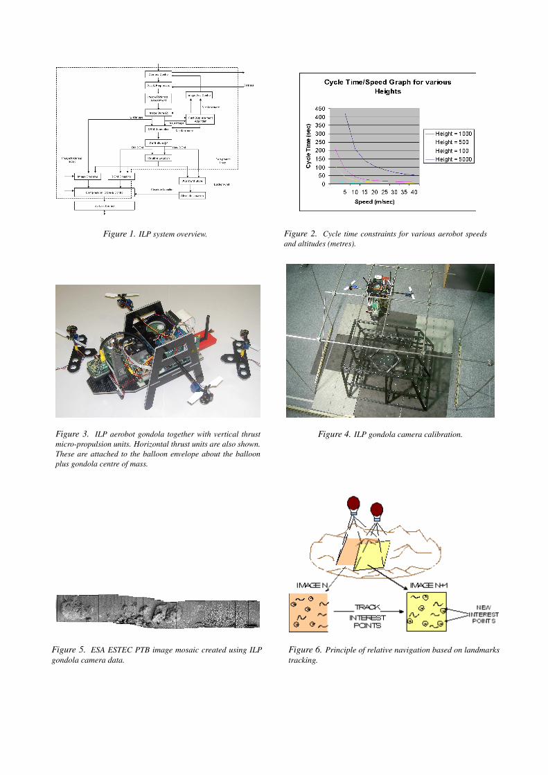
Figure 1. ILP system overview. Figure 2. Cycle time constraints for various aerobot speedsand altitudes (metres).
Figure 3. ILP aerobot gondola together with vertical thrustmicro-propulsion units. Horizontal thrust units are also shown.These are attached to the balloon envelope about the balloonplus gondola centre of mass.
Figure 4. ILP gondola camera calibration.
Figure 5. ESA ESTEC PTB image mosaic created using ILPgondola camera data.
Figure 6. Principle of relative navigation based on landmarkstracking.
tion (e.g. star/Sun trackers), or short-term information(e.g. gyros, Doppler radar). Therefore landmarks track-ing on the aerobot captured camera images could be useddirectly for relative localisation. This process thus fill-ing the gap between that of short term location sensors,and that of absolute localisation using an orbiter gener-ated DEM, such that the position and pointing of the aer-obot platform is known at any time.
3. LOCALISATION - RELATIVE
The accuracy of relative navigation by image based 2Dlandmarks tracking depends on a set of key parameters.They can be divided into system parameters (e.g. cam-era resolution, FOV, camera calibration), and situationdependent parameters which induce a set of different op-tions depending on the availability of information sourcesapart from the images. Our relative localisation methodemploys a landmark tracking algorithm that is used to fol-low upon the tracks of homologue points, called InterestPoints (IP), in two subsequent images. Correspondingdisplacements between the IP are then used as a data basefor calibration update. To extract the landmarks from theorigin image an interest operator is used. The essenceof the calibration update method (i.e. identifying an in-stant camera position and pointing parameters along theaerobot path) is given as follows.
Consider two consecutive images (frames N and N + 1,see Fig. 6) taken from the aerobot during motion. Whenframe N is involved in DEM generation, the 3D coordi-nates of the IP on frame N can be calculated from thisDEM. Having these 3D coordinates and their 2D coordi-nates from tracking between frame N and frame N +1, acalibration can be performed to obtain position and point-ing parameters of frame N+1. Further on, new IPs can beidentified in frame N + 1, and using the exterior orienta-tion from tracking calibration, these can be reconstructedin 3D. The procedure can then continue with frame N +2making use of all 3D coordinates of the N + 1 IPs. If noDEM is available for frame N , then 3D coordinates forthe IPs can still be calculated from the frame N to N + 1by tracking vectors and a scale factor from altimetry ordisplacement estimates (which provide information forrelative orientation between frame N and N + 1), againallowing continuation with frame N + 2. A thoroughanalysis of this tracking method has been undertaken (6),and experiments with a rover configuration and consid-erable horizontal displacement showed similar behaviour(7). Based upon this research, our relative localisationmethod is in the range of 1% of a distance to ground d,when travelling horizontally a displacement of d.
4. LOCALISATION - ABSOLUTE
To maintain localisation accuracy over large aerobotflight distances, our ILP approach augments our relativelocalisation data with an additional absolute localisation
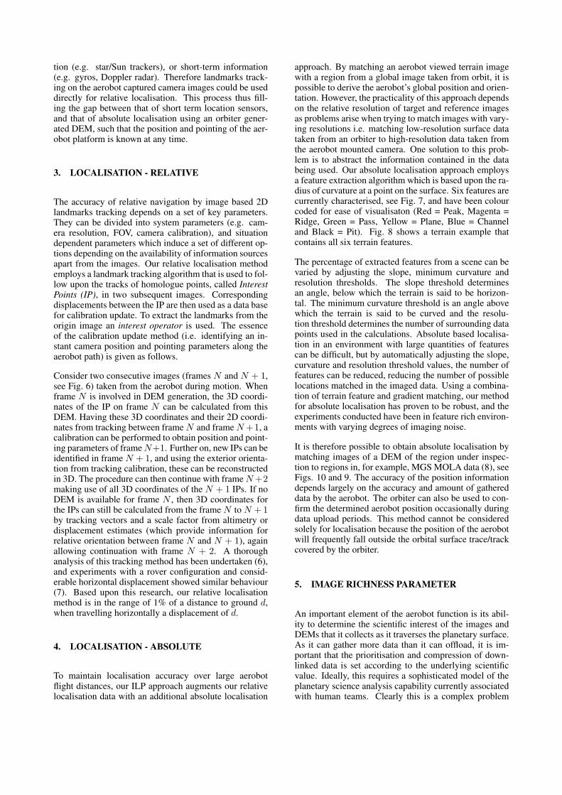
approach. By matching an aerobot viewed terrain imagewith a region from a global image taken from orbit, it ispossible to derive the aerobot’s global position and orien-tation. However, the practicality of this approach dependson the relative resolution of target and reference imagesas problems arise when trying to match images with vary-ing resolutions i.e. matching low-resolution surface datataken from an orbiter to high-resolution data taken fromthe aerobot mounted camera. One solution to this prob-lem is to abstract the information contained in the databeing used. Our absolute localisation approach employsa feature extraction algorithm which is based upon the ra-dius of curvature at a point on the surface. Six features arecurrently characterised, see Fig. 7, and have been colourcoded for ease of visualisaton (Red = Peak, Magenta =Ridge, Green = Pass, Yellow = Plane, Blue = Channeland Black = Pit). Fig. 8 shows a terrain example thatcontains all six terrain features.
The percentage of extracted features from a scene can bevaried by adjusting the slope, minimum curvature andresolution thresholds. The slope threshold determinesan angle, below which the terrain is said to be horizon-tal. The minimum curvature threshold is an angle abovewhich the terrain is said to be curved and the resolu-tion threshold determines the number of surrounding datapoints used in the calculations. Absolute based localisa-tion in an environment with large quantities of featurescan be difficult, but by automatically adjusting the slope,curvature and resolution threshold values, the number offeatures can be reduced, reducing the number of possiblelocations matched in the imaged data. Using a combina-tion of terrain feature and gradient matching, our methodfor absolute localisation has proven to be robust, and theexperiments conducted have been in feature rich environ-ments with varying degrees of imaging noise.
It is therefore possible to obtain absolute localisation bymatching images of a DEM of the region under inspec-tion to regions in, for example, MGS MOLA data (8), seeFigs. 10 and 9. The accuracy of the position informationdepends largely on the accuracy and amount of gathereddata by the aerobot. The orbiter can also be used to con-firm the determined aerobot position occasionally duringdata upload periods. This method cannot be consideredsolely for localisation because the position of the aerobotwill frequently fall outside the orbital surface trace/trackcovered by the orbiter.
5. IMAGE RICHNESS PARAMETER
An important element of the aerobot function is its abil-ity to determine the scientific interest of the images andDEMs that it collects as it traverses the planetary surface.As it can gather more data than it can offload, it is im-portant that the prioritisation and compression of down-linked data is set according to the underlying scientificvalue. Ideally, this requires a sophisticated model of theplanetary science analysis capability currently associatedwith human teams. Clearly this is a complex problem
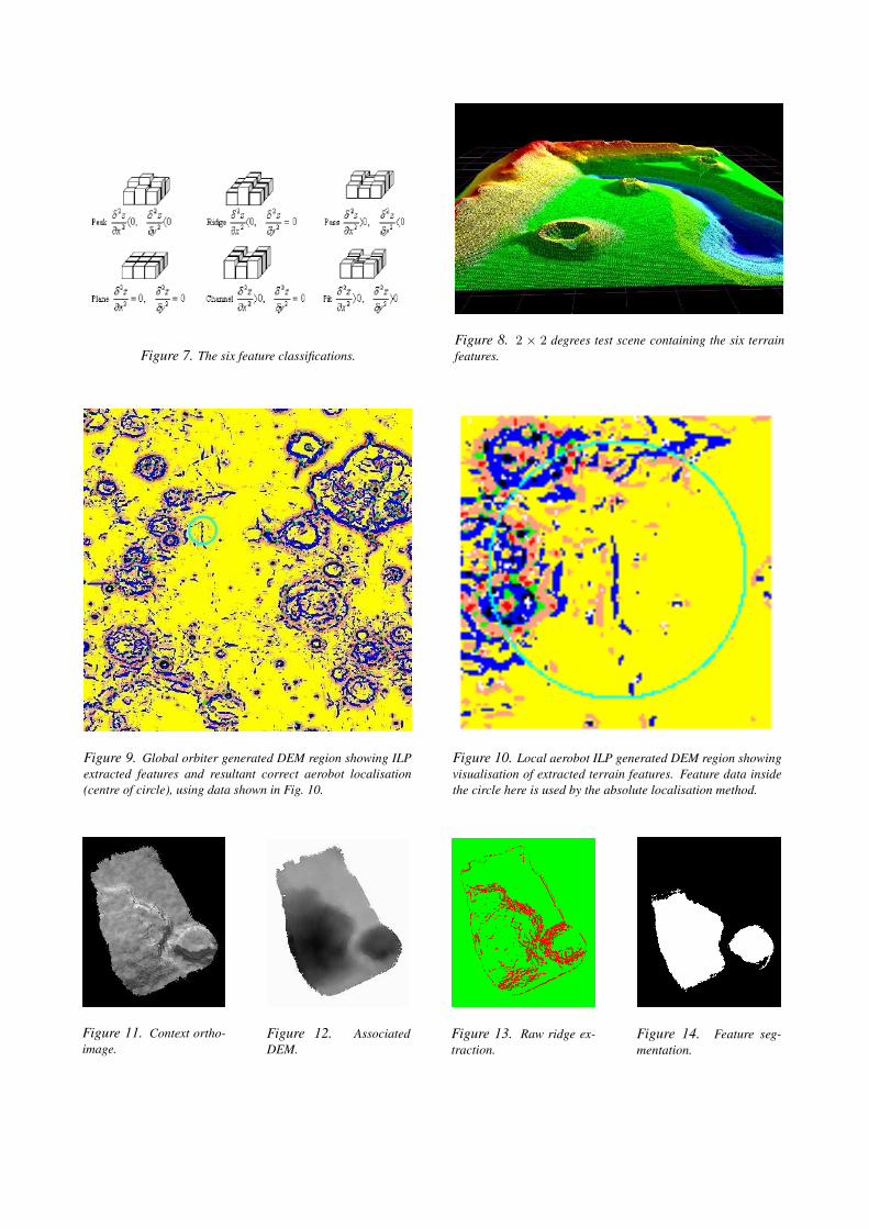
Figure 7. The six feature classifications.Figure 8. 2 × 2 degrees test scene containing the six terrainfeatures.
Figure 9. Global orbiter generated DEM region showing ILPextracted features and resultant correct aerobot localisation(centre of circle), using data shown in Fig. 10.
Figure 10. Local aerobot ILP generated DEM region showingvisualisation of extracted terrain features. Feature data insidethe circle here is used by the absolute localisation method.
Figure 11. Context ortho-image.
Figure 12. AssociatedDEM.
Figure 13. Raw ridge ex-traction.
Figure 14. Feature seg-mentation.
and the research area itself is relatively immature involv-ing a wide range of technology areas including computervision and various strands of AI. A further issue in thiswork is that the science assessment must be carried out inreal-time i.e. before the next image is taken as the aerobottransits the area. Time available for assessment dependson the speed and altitude of the aerobot.
The science members of the team defined a set of fea-tures of interest at a number of levels. At the primary‘first-pass’ level were significant geomorphological fea-tures such as impact craters, channels, volcanos, dunesetc. At the secondary level, evidence of features suchas cross-bedding which could be used to distinguish be-tween volcanic or aqueous channel creation are consid-ered important. Our work focused on the detection ofthese primary features in the first instance to generatea gross assessment of an individual area. Based on thescience team input we have assumed, that altitude has a‘fractal effect’ on the representation of features in the im-ages. For practical purposes therefore, our detection algo-rithms consider feature structure to be effectively invari-ant to this parameter. Consequently, macro or contextualrelationships between nested features are not consideredin this phase of detection.
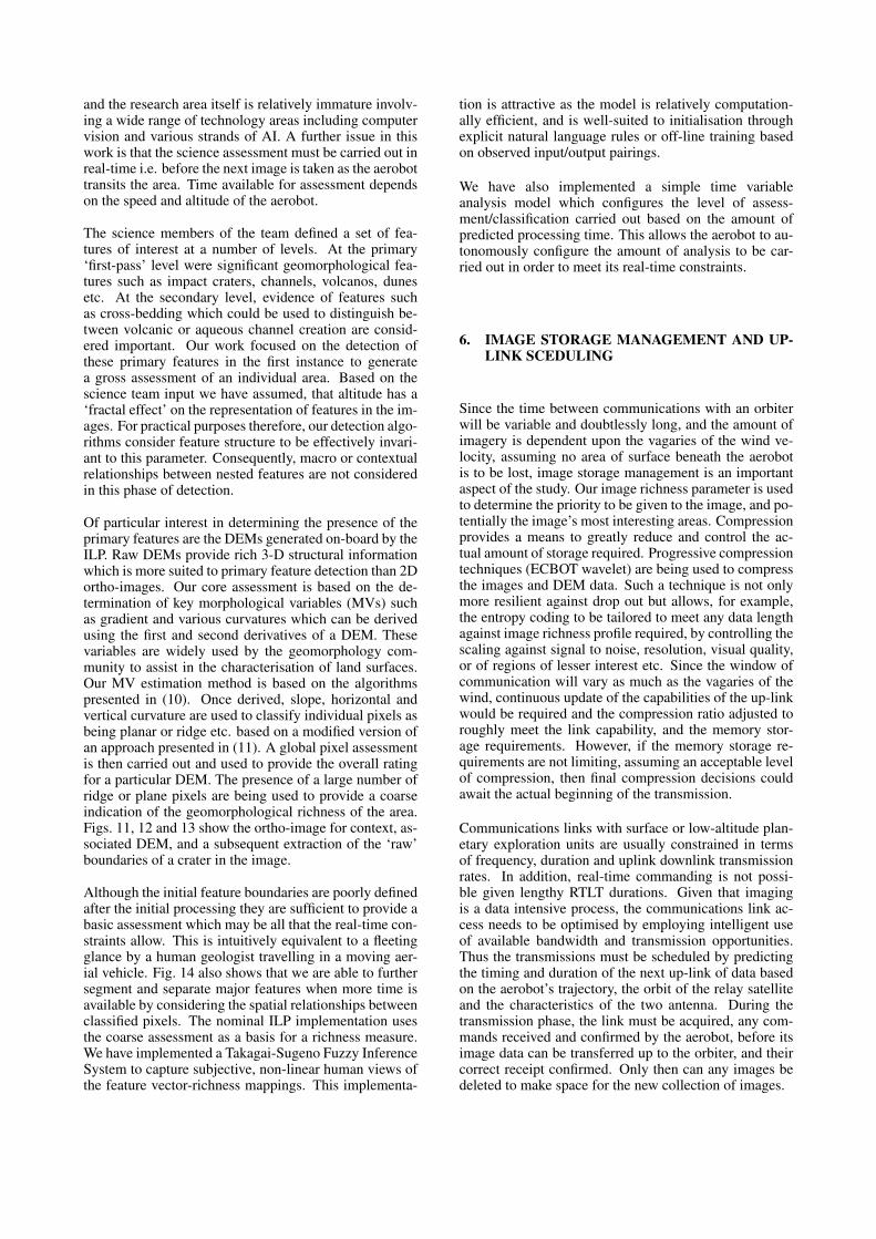
Of particular interest in determining the presence of theprimary features are the DEMs generated on-board by theILP. Raw DEMs provide rich 3-D structural informationwhich is more suited to primary feature detection than 2Dortho-images. Our core assessment is based on the de-termination of key morphological variables (MVs) suchas gradient and various curvatures which can be derivedusing the first and second derivatives of a DEM. Thesevariables are widely used by the geomorphology com-munity to assist in the characterisation of land surfaces.Our MV estimation method is based on the algorithmspresented in (10). Once derived, slope, horizontal andvertical curvature are used to classify individual pixels asbeing planar or ridge etc. based on a modified version ofan approach presented in (11). A global pixel assessmentis then carried out and used to provide the overall ratingfor a particular DEM. The presence of a large number ofridge or plane pixels are being used to provide a coarseindication of the geomorphological richness of the area.Figs. 11, 12 and 13 show the ortho-image for context, as-sociated DEM, and a subsequent extraction of the ‘raw’boundaries of a crater in the image.
Although the initial feature boundaries are poorly definedafter the initial processing they are sufficient to provide abasic assessment which may be all that the real-time con-straints allow. This is intuitively equivalent to a fleetingglance by a human geologist travelling in a moving aer-ial vehicle. Fig. 14 also shows that we are able to furthersegment and separate major features when more time isavailable by considering the spatial relationships betweenclassified pixels. The nominal ILP implementation usesthe coarse assessment as a basis for a richness measure.We have implemented a Takagai-Sugeno Fuzzy InferenceSystem to capture subjective, non-linear human views ofthe feature vector-richness mappings. This implementa-
tion is attractive as the model is relatively computation-ally efficient, and is well-suited to initialisation throughexplicit natural language rules or off-line training basedon observed input/output pairings.
We have also implemented a simple time variableanalysis model which configures the level of assess-ment/classification carried out based on the amount ofpredicted processing time. This allows the aerobot to au-tonomously configure the amount of analysis to be car-ried out in order to meet its real-time constraints.
6. IMAGE STORAGE MANAGEMENT AND UP-LINK SCEDULING
Since the time between communications with an orbiterwill be variable and doubtlessly long, and the amount ofimagery is dependent upon the vagaries of the wind ve-locity, assuming no area of surface beneath the aerobotis to be lost, image storage management is an importantaspect of the study. Our image richness parameter is usedto determine the priority to be given to the image, and po-tentially the image’s most interesting areas. Compressionprovides a means to greatly reduce and control the ac-tual amount of storage required. Progressive compressiontechniques (ECBOT wavelet) are being used to compressthe images and DEM data. Such a technique is not onlymore resilient against drop out but allows, for example,the entropy coding to be tailored to meet any data lengthagainst image richness profile required, by controlling thescaling against signal to noise, resolution, visual quality,or of regions of lesser interest etc. Since the window ofcommunication will vary as much as the vagaries of thewind, continuous update of the capabilities of the up-linkwould be required and the compression ratio adjusted toroughly meet the link capability, and the memory stor-age requirements. However, if the memory storage re-quirements are not limiting, assuming an acceptable levelof compression, then final compression decisions couldawait the actual beginning of the transmission.
Communications links with surface or low-altitude plan-etary exploration units are usually constrained in termsof frequency, duration and uplink downlink transmissionrates. In addition, real-time commanding is not possi-ble given lengthy RTLT durations. Given that imagingis a data intensive process, the communications link ac-cess needs to be optimised by employing intelligent useof available bandwidth and transmission opportunities.Thus the transmissions must be scheduled by predictingthe timing and duration of the next up-link of data basedon the aerobot’s trajectory, the orbit of the relay satelliteand the characteristics of the two antenna. During thetransmission phase, the link must be acquired, any com-mands received and confirmed by the aerobot, before itsimage data can be transferred up to the orbiter, and theircorrect receipt confirmed. Only then can any images bedeleted to make space for the new collection of images.
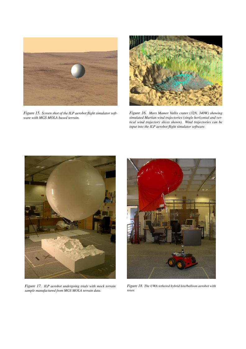
Figure 15. Screen shot of the ILP aerobot flight simulator soft-ware with MGS MOLA based terrain.
Figure 16. Mars Mamer Vallis crater (32N, 340W) showingsimulated Martian wind trajectories (single horizontal and ver-tical wind trajectory slices shown). Wind trajectories can beinput into the ILP aerobot flight simulator software.
Figure 17. ILP aerobot undergoing trials with mock terrainsample manufactured from MGS MOLA terrain data.
Figure 18. The UWA tethered hybrid kite/balloon aerobot withrover.

7. ILP DEMONSTRATOR OVERVIEW
Our ILP demonstrator system has two distinct modes.A hardware mode that encompasses a real balloon withgondola running the ILP software, and a balloon simula-tor. Both modes are interfaced to a demonstrator shell.Fig. 17 shows laboratory trials with our ILP aerobot fly-ing over a sample of mock Martian terrain that has beenmanufactured from 1m2 polystyrene blocks using MGSMOLA terrain data.
Using our aerobot flight simulator, terrain, weather, at-mosphere and hardware devices, such as cameras, can besimulated in a realistic way and noise can be modelledto allow for random fluctuations in the environment, ormanufacturing tolerances for instruments, see Fig. 15.
A major factor in the deployment of planetary balloonsis the effect the environment and atmospheric conditionshave upon the balloon. Wind could potentially affect theperformance of the ILP and therefore must be modelled toprovide as realistic a simulation as is practicable. Our ILPaerobot flight simulator allows ‘realistic’ Martian windsto be used to propel the balloon over the simulated terrain,see Fig. 16. We use a 3D Navier-Stokes solver that canbe initialised with both Mars terrain (e.g. MGS MOLAdata), and meteorological data from, for example, theESA Mars Climate Data base (9). The output from thisprocess is a data structure containing Martian wind u, v,w vectors, and for any given simulated balloon latitude,longitude, altitude and time, the appropriate vectors canbe used by the simulation to propel the balloon.
Our demonstrator software shell provides a number offunctions, ranging from the control of the balloon hard-ware and simulator, presentation of data gathered andeventual evaluation of the complete system and ILP per-formance. To this end the demonstrator shell softwareencompasses enough flexibility to be able to efficientlyand effectively perform all these tasks and experiments.The demonstrator shell has to communicate with both thereal balloon hardware, and the balloon simulator in orderto receive up-linked DEMs and images and to downloadcamera models and balloon trajectory information. Theshell allows selection of the demonstration mode, hard-ware or software, provides an interface to allow selectionand upload of camera, antenna and terrain models and en-ables the user to define the communication window func-tion.
8. CONCLUSION
An overview of the rationale for sending a LTA aerobotto Mars has been presented. Whilst there are many chal-lenges, we believe that the technology ‘building blocks’are available to launch a planetary exploration roboticballoon to Mars within the next launch opportunity win-dows (2009, 2011, 2013). We are using a novel com-bination of imaged based relative and absolute localisa-
tion techniques to ensure a robust solution to the problemof Martian aerobot localisation. We are demonstratingour ILP using both simulated and real aerobot data, andthereby providing a comprehensive test and evaluation ofour ILP functionality. Building upon our ILP research,we are examining also the application of a number of ourdeveloped imaging and DEM generation methods to teth-ered aerobot vehicles, see Fig. 18. Such technology couldbe integrated with future rovers and landers. In the con-text of a future Mars sample return mission, for example,such a vehicle could provide invaluable landing site aer-ial surveying and meteorology prior to a fetch rover beingsent to obtain a Mars surface and sub/surface sample. Wewill report on our tethered aerobot work in the future lit-erature.
REFERENCES
[1] Stone H.W., “Mars Pathfinder Microrover a Small, Low-cost, Low-power Spacecraft,” Jet Propulsion Laboratory,1996.
[2] Squyres S.W., et al, “The Spirit Rover’s Athena ScienceInvestigation at Gusev Crater, Mars,” Science, 305: pp.794-799, August 2004.
[3] Barnes D.P., Summers P., Shaw A., “An Investigationinto Aerobot Technologies for Planetary Exploration,” 6thESA Workshop on Advanced Space Technologies for Ro-botics and Automation, ASTRA 2000, 3.6-5, Dec. 2000.
[4] Woods M., Evans M., Ward R., Barnes D., Shaw A., Sum-mers P., Paar G., and Sims M., “Developing an Au-tonomous Imaging and Localisation Capability for Plan-etary Aerobots,” 5th IFAC/EURON Symposium on Intelli-gent Autonomous Vehicles, pp. 509-515, July 2004.
[5] Barnes D.P., Phillips N., and Paar G., “Beagle 2 Sim-ulation and Calibration for Ground Segment Operations,”7th Int. Symposium on Artificial Intelligence, Robotics andAutomation in Space (i-SAIRAS), Japan, 2003. CD-ROMproceedings.
[6] Paar G., et al, “Vision-Based Navigation for Moon Land-ing,” Final Report for ESTEC purchase order 142958,ESTEC, December. 1994.
[7] Kolesnik M., Paar G., “Algorithmic Solution and Simu-lation Results for Vision-Based Autonomous Mode of aPlanetary Rover,” Proc. 7th Int. Conference on ComputerAnalysis of Images and Patterns, Kiel, Germany, pp. 10-12, 1997.
[8] Shaw A.J., Barnes D.P., “Landmark Recognition for Lo-calisation and Navigation of Aerial Vehicles,” IEEE/RSJInt. Conference on Intelligent Robots and Systems (IROS),Las Vegas, October 2003.
[9] Lewis S.R., et al, “A Climate Database for Mars,” J. Geo-phys. Research-Planets, Vol. 104 , No. E10, pp. 24,177-24,194, 1999.
[10] Shary P.A., Sharaya L.S., Mitusov A.V., “Fundamentalquantitative methods of land surface analysis,” Geoderma,107(1-2), 1-32, 2002.
[11] Wood J., “The Geomorpholological Characterisation ofDigital Elevation Models,” PhD Thesis, University ofLeicester, UK. 1996.