Embed Size (px)
Citation preview
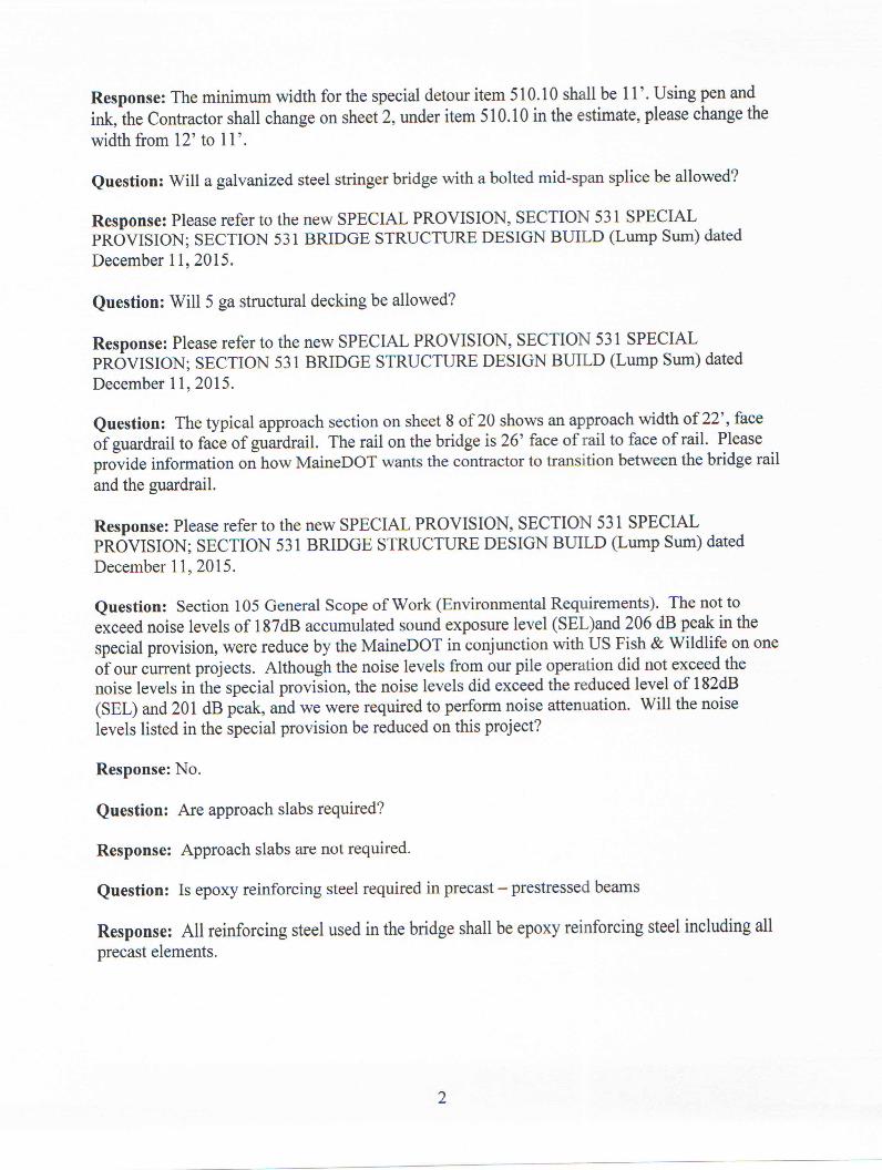

Maine Department of Transportation
12/14/2015
Proposal ID: 017881.00 Project(s): 017881.00
1 INITIAL GROUPSECTION:
Alt Set ID: Alt Mbr ID:
Contractor:
Bid AmountUnit PriceApproximateQuantity and
UnitsDescription
Item IDProposal
LineNumber Dollars Cents Dollars Cents
_________._____
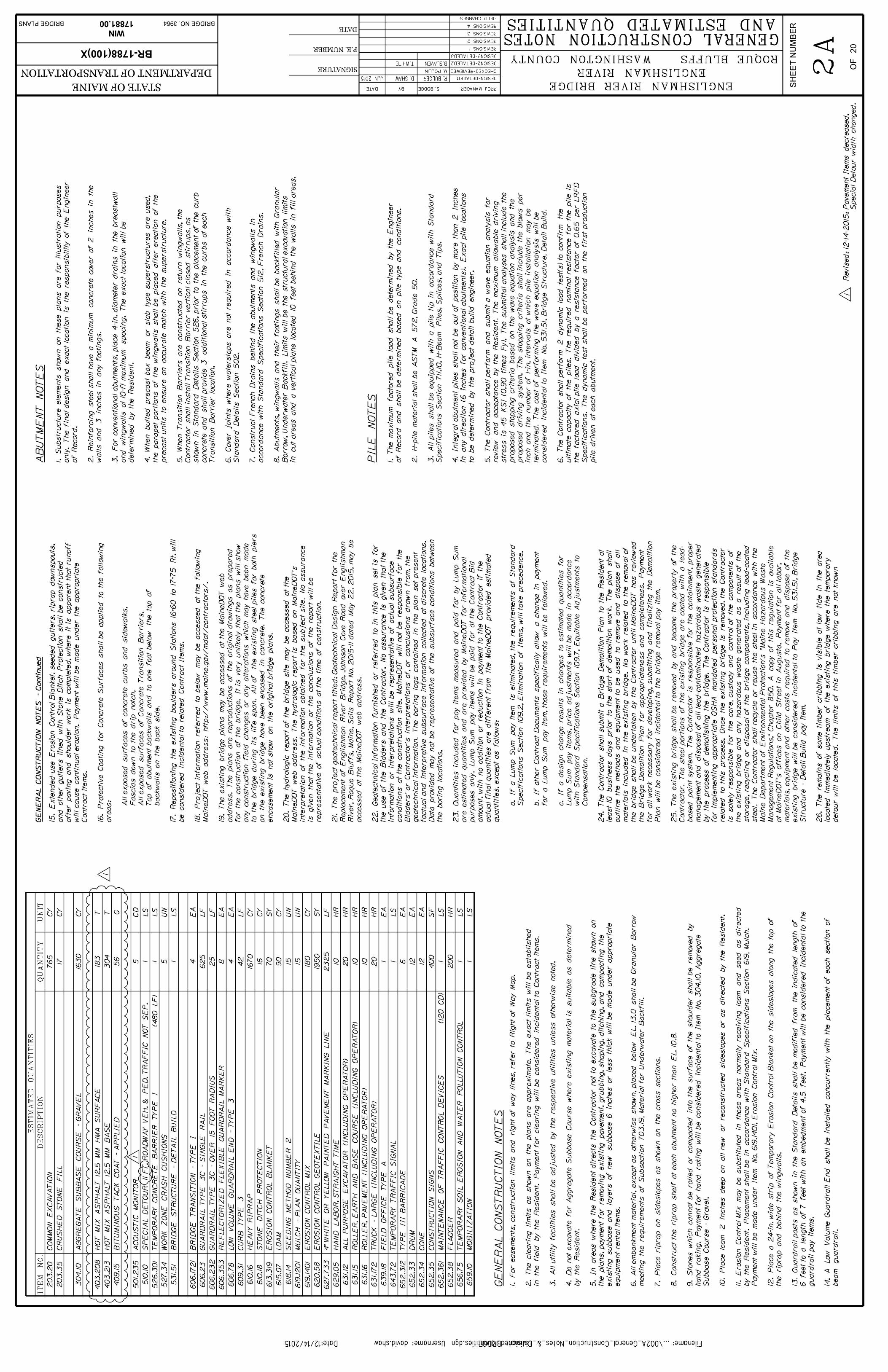
0010 203.20
COMMON EXCAVATION CY
765.000
_________._____
_________._____
0020 203.35
CRUSHED STONE FILL CY
17.000
_________._____
_________._____
0030 304.10
AGGREGATE SUBBASE COURSE -GRAVEL
CY
1,630.000
_________._____
_________._____
0040 403.208
HOT MIX ASPHALT 12.5 MM HMASURFACE
T
183.000
_________._____
_________._____
0050 403.213
HOT MIX ASPHALT 12.5 MM BASE T
304.000
_________._____
_________._____
0060 409.15
BITUMINOUS TACK COAT - APPLIED G
56.000
_________._____
_________._____
0070 501.235
ACOUSTIC MONITOR CD
5.000
_________._____
0080 510.10
SPECIAL DETOUR_____ROADWAYWIDTH VEHICULAR & PEDESTRIANTRAFFIC NOT SEPARATED 11 FT
_________._____LUMP SUM LUMP SUM
0090 526.301
TEMPORARY CONCRETE BARRIERTYPE I
_________._____LUMP SUM LUMP SUM
_________._____
0100 527.34
WORK ZONE CRASH CUSHIONS UN
5.000
_________._____
0110 531.51
BRIDGE STRUCTURE - DETAIL BUILD _________._____LUMP SUM LUMP SUM
_________._____
0120 606.1721
BRIDGE TRANSITION - TYPE 1 EA
4.000
_________._____
Proposal Schedule of Items Page 1 of 4
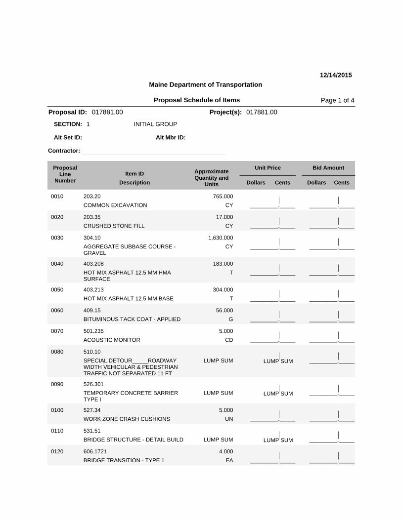
Maine Department of Transportation
12/14/2015
Proposal ID: 017881.00 Project(s): 017881.00
1 INITIAL GROUPSECTION:
Alt Set ID: Alt Mbr ID:
Contractor:
Bid AmountUnit PriceApproximateQuantity and
UnitsDescription
Item IDProposal
LineNumber Dollars Cents Dollars Cents
_________._____
0130 606.23
GUARDRAIL TYPE 3C - SINGLE RAIL LF
625.000
_________._____
_________._____
0140 606.232
GUARDRAIL TYPE 3C - OVER 15FOOT RADIUS
LF
25.000
_________._____
_________._____
0150 606.353
REFLECTORIZED FLEXIBLEGUARDRAIL MARKER
EA
8.000
_________._____
_________._____
0160 606.78
LOW VOLUME GUARDRAIL END -TYPE 3
EA
4.000
_________._____
_________._____
0170 609.31
CURB TYPE 3 LF
42.000
_________._____
_________._____
0180 610.16
HEAVY RIPRAP CY
1,670.000
_________._____
_________._____
0190 610.18
STONE DITCH PROTECTION CY
16.000
_________._____
_________._____
0200 613.319
EROSION CONTROL BLANKET SY
70.000
_________._____
_________._____
0210 615.07
LOAM CY
90.000
_________._____
_________._____
0220 618.14
SEEDING METHOD NUMBER 2 UN
15.000
_________._____
_________._____
0230 619.1201
MULCH - PLAN QUANTITY UN
15.000
_________._____
_________._____
0240 619.1401
EROSION CONTROL MIX - PLANQUANTITY
CY
180.000
_________._____
Proposal Schedule of Items Page 2 of 4
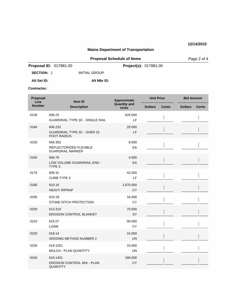
Maine Department of Transportation
12/14/2015
Proposal ID: 017881.00 Project(s): 017881.00
1 INITIAL GROUPSECTION:
Alt Set ID: Alt Mbr ID:
Contractor:
Bid AmountUnit PriceApproximateQuantity and
UnitsDescription
Item IDProposal
LineNumber Dollars Cents Dollars Cents
_________._____
0250 620.58
EROSION CONTROL GEOTEXTILE SY
1,950.000
_________._____
_________._____
0260 627.733
4" WHITE OR YELLOW PAINTEDPAVEMENT MARKING LINE
LF
2,325.000
_________._____
_________._____
0270 629.05
HAND LABOR, STRAIGHT TIME HR
10.000
_________._____
_________._____
0280 631.12
ALL PURPOSE EXCAVATOR(INCLUDING OPERATOR)
HR
20.000
_________._____
_________._____
0290 631.15
ROLLER, EARTH AND BASE COURSE(INCLUDING OPERATOR )
HR
10.000
_________._____
_________._____
0300 631.16
ROLLER, PAVEMENT (INCLUDINGOPERATOR)
HR
10.000
_________._____
_________._____
0310 631.172
TRUCK - LARGE (INCLUDINGOPERATOR)
HR
20.000
_________._____
_________._____
0320 639.18
FIELD OFFICE TYPE A EA
1.000
_________._____
0330 643.72
TEMPORARY TRAFFIC SIGNAL _________._____LUMP SUM LUMP SUM
_________._____
0340 652.312
TYPE III BARRICADE EA
6.000
_________._____
_________._____
0350 652.33
DRUM EA
12.000
_________._____
_________._____
0360 652.34
CONE EA
12.000
_________._____
Proposal Schedule of Items Page 3 of 4
Maine Department of Transportation
12/14/2015
Proposal ID: 017881.00 Project(s): 017881.00
1 INITIAL GROUPSECTION:
Alt Set ID: Alt Mbr ID:
Contractor:
Bid AmountUnit PriceApproximateQuantity and
UnitsDescription
Item IDProposal
LineNumber Dollars Cents Dollars Cents
_________._____
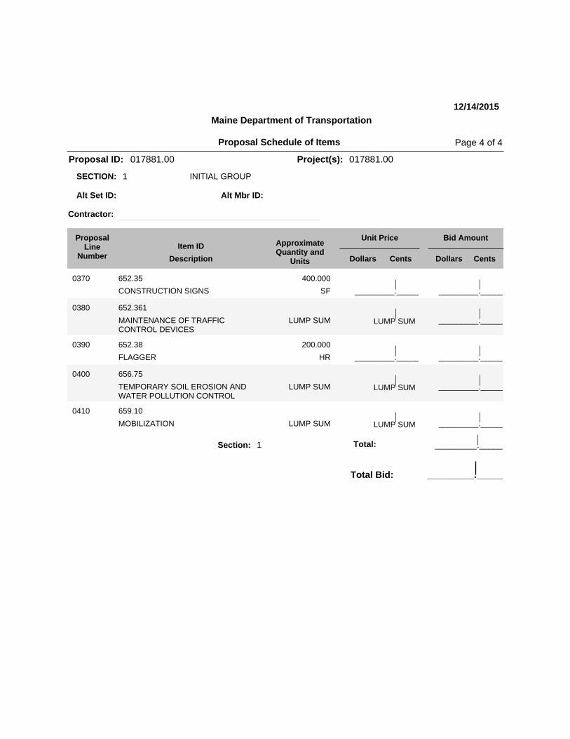
0370 652.35
CONSTRUCTION SIGNS SF
400.000
_________._____
0380 652.361
MAINTENANCE OF TRAFFICCONTROL DEVICES
_________._____LUMP SUM LUMP SUM
_________._____
0390 652.38
FLAGGER HR
200.000
_________._____
0400 656.75
TEMPORARY SOIL EROSION ANDWATER POLLUTION CONTROL
_________._____LUMP SUM LUMP SUM
0410 659.10
MOBILIZATION _________._____LUMP SUM LUMP SUM
Section: 1 _________._____Total:
Total Bid: _________._____
Proposal Schedule of Items Page 4 of 4
December 5, 2011 Supersedes December 1, 2010
1 of 1
SPECIAL PROVISION SECTION 105
GENERAL SCOPE OF WORK (Buy America Certification)
105.11 Federal Requirements Add the following as the third and subsequent paragraphs: “Prior to payment by the Department, the Contractor shall provide a certification from the producer of steel or iron, or any product containing steel or iron as a component, stating that all steel or iron furnished or incorporated into the furnished product was manufactured in the United States in accordance with the requirements of the Buy America provisions of 23 CFR 635.410, as amended. Such certification shall also include (1) a statement that the iron or steel product or component was produced entirely within the United States, or (2) a statement that the iron or steel product or component was produced within the United States except for minimal quantities of foreign steel and iron valued at $ (actual value). All manufacturing processes must take place domestically. Manufacturing begins with the initial melting and mixing, and continues through the coating stage. Any process which modifies the chemical content, the physical size and shape, or the final finish is considered a manufacturing process. These processes include rolling, extruding, machining, bending, grinding, drilling, and coating. “Coating” includes epoxy coating, galvanizing, painting, or any other coating that protects or enhances the value of the material. A Buy America Certification is required from each manufacturer, fabricator, supplier, subcontractor, etc. that meets the “manufacturing” definition above. Buy America does not apply to raw materials (iron ore and alloys), scrap, pig iron, or processed, pelletized, and reduced iron ore.”
Roque Bluffs WIN 017881.00
December 11, 2015
Page 1 of 5
SPECIAL PROVISION SECTION 531
BRIDGE STRUCTURE DETAIL BUILD (Lump Sum)
DESCRIPTION This work shall consist of the design and construction of an integral abutment pile supported, precast concrete beam or Hybrid-Composite Beam (HCB®)(single web with vertical sides), simple span bridge in accordance with these specifications, and in close conformity with the lines and grades shown on the Plans. This work shall include the following: Removal of the Existing Bridge Design, Load Rating, and Detailing of the new bridge superstructure Design and Detailing of the new bridge substructures, retaining walls, and foundations
Furnishing and installing in-place Steel H-Beam Piles including equipment mobilization, pile tips and splices Structural Earth Excavation
Dynamic Loading Tests of Piles Granular and gravel borrow All Structural Concrete including quality control and curing box(s) Fabrication, Delivery, and Placing of all reinforcing steel Bridge rails and permanent transition barriers High Performance Waterproofing Membrane French Drains
Protective Coating for Concrete Surfaces Permanent Concrete Transition Barriers
Furnishing and installing of any bearings, bearing pads, anchor bolts, and other devices utilized by the design to accommodate superstructure to substructure loads
Some of the items listed above may not be applicable, depending on the structure option chosen. DETAIL BUILD OPTIONS
1. Precast/prestressed concrete butted box beams with a 5” minimum thickness reinforced concrete slab superstructure on integral abutment foundations.
2. Precast/prestressed concrete spread box beams with 8” minimum thick reinforced concrete deck on integral abutment foundation.
3. Precast/prestressed concrete PCI NEXT beam (F or E) superstructure on integral
abutment foundations.
Roque Bluffs WIN 017881.00
December 11, 2015
Page 2 of 5
4. Precast/prestressed concrete PCI NE Bulb Tee beam superstructure with 8” minimum thick reinforced concrete deck on integral abutment foundations.
5. Hillman Hybrid Composite Beam (single web with vertical sides) superstructure
with 8” minimum thick reinforced concrete deck on integral abutment foundations.
6. Metallized welded steel plate girders (50 ksi minimum for steel plate) with 8”
minimum thick reinforced concrete deck on integral abutment foundation. The bridge shall have a minimum of 4 beam lines. Bolted field splices shall not be located within 12’ of the midpoint of the beam. The steel beams and all diaphragms or cross frames used on the bridge shall be metallized in accordance with subsections 506.30 to 506.39 “THERMAL SPRAY COATING”.
DESIGN REQUIREMENTS The bridge structure, including foundation elements, shall be designed by a Professional Engineer (Engineer of Record) licensed in the State of Maine. The design shall be in accordance with the latest editions of the AASHTO LRFD Bridge Design Specifications, the MaineDOT Bridge Design Guide, Project Specific MaineDOT Special Provisions, MaineDOT Standard Details, and MaineDOT Standard Specifications. The minimum elevation for the superstructure bottom chord is elevation 12.0’. The bridge design shall be independently checked by a Professional Engineer (different than the Engineer of Record) licensed in the State of Maine. The clear span between abutment faces shall be a minimum 84 feet. The span from centerline of bearing to centerline of bearing shall be a minimum of 86 feet and shall be centered over the stream (approximately station 13+60). The bridge shall have no skew. The bridge curb to curb width shall be 22 feet consisting of two 11 foot travel lanes. The roadway cross section over the bridge shall match the design of the approaches as shown in the contract drawings, except that there shall be no cross-slope change from travel lane to shoulder. Regardless of the bridge structure chosen and design span, construction of the temporary detour shall stay within the temporary construction limits and the finished bridge structure shall be within the proposed right-of-way limits. The bridge shall meet a modified HL-93 live load. The modification to the HL-93 loading shall be an increase in the truck live load by 25% for the Strength I load combination only; all other load combinations shall use the standard HL-93 live load. Extreme limit state check of abutment piles will not be required for scour given that heavy riprap countermeasure is specified. The geotechnical design and foundation construction shall follow the recommendations of the Geotechnical Design Report for the Replacement of Englishman River Bridge, Johnson Cove Road over Englishman River, Roque Bluffs, Maine (Soils Report No. 2015-11) as
Roque Bluffs WIN 017881.00
December 11, 2015
Page 3 of 5
appropriate for the Bridge Structure option chosen, and be in accordance with the latest editions of the AASHTO LRFD Bridge Design Specifications, the MaineDOT Bridge Design Guide, Project specific MaineDOT Special Provisions, MaineDOT Standard Details, and MaineDOT Standard Specifications. All design options shall be load rated in accordance with the AASHTO Manual for Bridge Evaluation, latest edition by the LRFR method, and MaineDOT Load Rating Guide. Each design option shall be rated based on the HL-93 live load and the HL-93 modified live load. The live load rating computations shall include a completed MaineDOT Summary of Rating Form based on the rating factors for the HL-93 live load only. The MaineDOT Summary of Rating Form may be accessed at the following MaineDOT web Address under the applicable project: http://www.maine.gov/mdot/contractors/ . The top 2 feet of the steel H pile below the bottom of the integral abutment shall be encased with fill concrete that extends a minimum of 4 inches beyond edge of the piles. DETAIL BUILD OPTIONS #1 and #3 shall have a 3” bituminous wearing surface with high performance membrane waterproofing from the Qualified Products List. DETAIL BUILD OPTIONS #2, #4, #5 and #6 shall have a 1inch integral concrete wearing surface. All reinforcing steel in the bridge shall be epoxy coated. The bridge shall have a cast in place concrete curb as shown on MaineDOT standard detail 502 (04) or 502(05). The bridge shall use 2 bar steel bridge railing in accordance with MaineDOT standard detail 507 (03) and 502(04). Permanent Concrete Transition barrier for 2 bar traffic railing shall be used on all four corners of the bridge. The use of stay in place metal formwork shall not be allowed. Protective Coating for Concrete Surfaces Shall be used in the following locations:
1. All exposed surfaces of concrete curbs 2. Fascia down to drip notch, 3. All exposed surfaces of concrete transition barriers 4. Concrete wearing surface, if used
MATERIALS Material requirements are covered in the Project specific Special Provisions, MaineDOT Standard Specifications, and MaineDOT Bridge Design Guide and apply to all work included within this Special Provision with additional Project specific requirements listed below:
Roque Bluffs WIN 017881.00
December 11, 2015
Page 4 of 5
Buy America is applicable to this project. The only steel components anticipated are the H-piles and epoxy-coated reinforcement. Other than the H-piles, no uncoated steel components shall be installed below the top of the deck. Structural Concrete Concrete shall be as specified, Class A or Class P. Reinforcing steel shall be epoxy coated ASTM A615 – Gr. 60. Prestressing strand shall be AASHTO 203 (ASTM A416), Grade 270, Low Relaxation. Steel Hardware
Anchor rods and nuts shall conform to the requirements of ASTM F1554 galvanized in accordance with ASTM A153. Fasteners shall be ASTM A A325, type 1, galvanized in accordance with ASTM 153 unless noted otherwise.
SUBMITTALS The Contractor shall submit to the Department a formal design package submittal at the 50% design development stage containing plans that show the type of bridge structure to be constructed and an overall layout of the bridge including; a plan, profile, and typical section drawing. The Department shall have up to five business days to return comments on the 50% submittal. All comments by the Department shall be addressed by the Contractor with written verification of resolution from the Department prior to the final submittal. The final submittal shall be submitted by the Contractor to the Department electronically and shall include; final Design Drawings, Design Computations, Load Rating Computations, including MaineDOT Load Rating Form, and Design Check Computations for all bridge components. The Department shall have up to ten business days to return comments on the final submittal. All comments by the Department on the final submittal shall be addressed by the Contractor and verified by written approval from the Department prior to fabrication. The Design Computations and Load Rating Computations shall be signed and sealed by the Engineer of Record and the Engineer responsible for the design check. The contract drawings shall be signed and sealed by the Engineer of Record. Upon completion of Construction, the Contractor shall submit an electronic submission of as-built drawings signed and sealed by the Engineer of Record with any field changes or alterations noted. If any field changes or alterations do occur and will affect the bridge structure load capacity, the load rating shall be updated.
Roque Bluffs WIN 017881.00
December 11, 2015
Page 5 of 5
CONSTRUCTION REQUIREMENTS All included work shall meet the applicable sections of the Project specific Special Provisions, Standard Specifications, and Standard Details. Existing Bridge Removal – The existing superstructure shall be removed in its entirety and become property of the Contractor. The existing piles for the piers shall be removed 1’ below the streambed or the piles shall be removed in their entirety. The existing abutments as a minimum shall be removed to elevation 8.0’. Any existing piles that may interfere with the new substructure shall be removed by the Contractor. Any existing substructure removed shall become property of the Contractor. METHOD OF MEASUREMENT The accepted Bridge Structure will be measured by lump sum for the design, detailing, load rating, fabrication, delivery, and construction of the new Bridge Structure. BASIS OF PAYMENT The accepted Bridge Structure will be paid for at the contract lump sum price for the pay item listed below. Such payment shall be full compensation for removal of the existing bridge, all design, detailing, load rating, fabrication, delivery, and construction of one of the options listed under Detail Build Options, and all of the applicable items listed under Description required for that option. Items not listed under Description or that do not fall under other pay items shall be considered incidental to the pay item listed below except for Hot Mix Asphalt. Hot Mix Asphalt on the bridge shall not be paid for under the respective 403 items, but considered incidental. The individual items shall be governed by their respective Specifications and Special Provisions. The Lump Sum will be payable in installments as follows:
Upon removal of the existing bridge 10% Submission of the design plans and computations 10% Completion of Driven Piles 10% Completion of Abutment Concrete 10% Erection of superstructure and deck completion 50% Acceptance of Bridge and As-Built drawings 10%
Payment will be made under: Pay Item Pay Unit 531.51 Bridge Structure – Detail Build Lump Sum
East Machias WIN 017881.00
December 12, 2015
SPECIAL PROVISION SECTION 510
SPECIAL DETOUR (Horizontal Alignment)
Subsection 510.032”Geometric and Approach Design” part a Horizontal alignment is
replaced in its entirety with the following:
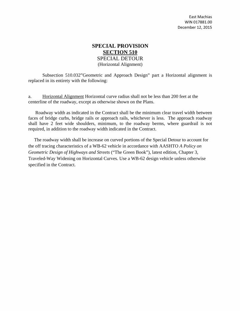
a. Horizontal Alignment Horizontal curve radius shall not be less than 200 feet at the centerline of the roadway, except as otherwise shown on the Plans.
Roadway width as indicated in the Contract shall be the minimum clear travel width between faces of bridge curbs, bridge rails or approach rails, whichever is less. The approach roadway shall have 2 feet wide shoulders, minimum, to the roadway berms, where guardrail is not required, in addition to the roadway width indicated in the Contract. The roadway width shall be increase on curved portions of the Special Detour to account for the off tracing characteristics of a WB-62 vehicle in accordance with AASHTO A Policy on Geometric Design of Highways and Streets (“The Green Book”), latest edition, Chapter 3, Traveled-Way Widening on Horizontal Curves. Use a WB-62 design vehicle unless otherwise specified in the Contract.
BRIDGE Division: Filename:...\002A_General_Construction_Notes_&_Estimated_Quantities.dgnUsername:Date:12/14/2015 david.shawE
ST
IM
AT
ED
QU
AN
TIT
IE
S
IT
EM
NO
.Q
UA
NT
ITY
DE
SC
RIP
TIO
NU
NIT
DESIGN-DETAILED
BYDATE PROJ. MANAGER SH
EE
T N
UM
BE
R
FIELD CHANGES
REVISIONS 1
REVISIONS 2
REVISIONS 3
REVISIONS 4
CHECKED-REVIEWED OFDESIGN2-DETAILED2
DESIGN3-DETAILED3
WIN
BRIDGE PLANS
DEPARTMENT OF TRANSPORTATION
STATE OF MAINE
DATE
SIGNATURE
P.E. NUMBERBR-1788(100)X 20
17881.00
ENGLISHMAN RIVER BRIDGE
ENGLISHMAN RIVER
ROQUE BLUFFSWASHINGTON COUNTY
BRIDGE NO. 3964
S. BODGE
GENERAL CONSTRUCTION NOTES
AND ESTIMATED QUANTITIES
B.SLAVENT.WHITE
JUN 2015 R. BULGERD. SHAW
AB
UT
ME
NT
NO
TE
S
PIL
E N
OT
ES
pil
e d
riv
en
at
each
ab
utm
en
t.
Sp
ecif
icati
on
s.
Th
e d
yn
am
ic t
est
sh
all
be p
erfo
rm
ed
on
th
e f
irst
pro
du
cti
on
the f
acto
red a
xia
l pil
e l
oad d
ivid
ed b
y a
resis
tance f
acto
r o
f 0
.65 p
er L
RF
D
ult
imate
capacit
y o
f t
he p
iles. T
he r
equir
ed n
om
inal
resis
tance f
or t
he p
ile i
s
6.
Th
e C
on
tracto
r s
hall
perfo
rm
2 d
yn
am
ic l
oad
test(
s) t
o c
on
fir
m t
he
consid
ered i
ncid
enta
l to
Ite
m N
o. 531.5
1, B
rid
ge S
tructu
re, D
eta
il B
uil
d.
term
inate
d.
Th
e c
ost
of p
erfo
rm
ing
th
e w
av
e e
qu
ati
on
an
aly
sis
wil
l b
e
inch
an
d t
he n
um
ber o
f 1
-in
. in
terv
als
at
wh
ich
pil
e i
nsta
llati
on
may
be
proposed d
riv
ing s
yste
m. T
he s
toppin
g c
rit
eria
shall
inclu
de t
he b
low
s p
er
proposed s
toppin
g c
rit
eria
based o
n t
he w
ave e
quati
on a
naly
sis
and t
he
str
ess i
s 4
5 K
SI (
0.9
0 t
imes F
y). T
he s
ubm
itta
l analy
ses s
hall
inclu
de t
he
revie
w a
nd a
ccepta
nce b
y t
he R
esid
ent.
T
he m
axim
um
all
ow
able
driv
ing
5.
Th
e C
on
tracto
r s
hall
perfo
rm
an
d s
ub
mit
a w
av
e e
qu
ati
on
an
aly
sis
fo
r
to b
e d
ete
rm
ined
by
th
e p
ro
ject
deta
il b
uil
d e
ng
ineer.
in a
ny d
irecti
on (
6 i
nches f
or c
onventi
onal
abutm
ents
). E
xact
pil
e l
ocati
ons
4. I
nte
gral
abutm
ent
pil
es s
hall
not
be o
ut
of p
osit
ion b
y m
ore t
han 2
inches
Sp
ecif
icati
on
s S
ecti
on
71
1.1
0, H
-B
eam
Pil
es, S
pli
ces, an
d T
ips.
3.
All
pil
es s
hall
be e
qu
ipp
ed
wit
h a
pil
e t
ip i
n a
cco
rd
an
ce w
ith
Sta
nd
ard
2. H
-pil
e m
ate
ria
l shall
be A
ST
M A
572, G
rade 5
0.
of R
eco
rd
an
d s
hall
be d
ete
rm
ined
based
on
pil
e t
yp
e a
nd
co
nd
itio
ns.
1. T
he m
axim
um
facto
red p
ile l
oad s
hall
be d
ete
rm
ined b
y t
he E
ngin
eer
GE
NE
RA
L C
ON
ST
RU
CT
ION
NO
TE
S
GE
NE
RA
L C
ON
ST
RU
CT
ION
NO
TE
S -
Co
nti
nu
ed
CO
MM
ON
EX
CA
VA
TIO
N
AG
GR
EG
AT
E S
UB
BA
SE
CO
UR
SE
- G
RA
VE
L
CR
US
HE
D S
TO
NE
FIL
L
HO
T M
IX A
SP
HA
LT
12.5
MM
HM
A S
UR
FA
CE
HO
T M
IX
AS
PH
AL
T 1
2.5
MM
BA
SE
BIT
UM
INO
US
TA
CK
CO
AT
- A
PP
LIE
D
TE
MP
OR
AR
Y C
ON
CR
ET
E B
AR
RIE
R T
YP
E I
WO
RK
ZO
NE
CR
AS
H C
US
HIO
NS
BR
ID
GE
ST
RU
CT
UR
E -
DE
TA
IL
BU
IL
D
BR
ID
GE
TR
AN
SIT
IO
N -
TY
PE
I
GU
AR
DR
AIL
TY
PE
3C
- S
IN
GL
E R
AIL
RE
FL
EC
TO
RIZ
ED
FL
EX
IBL
E G
UA
RD
RA
IL M
AR
KE
R
LO
W V
OL
UM
E G
UA
RD
RA
IL E
ND
- T
YP
E 3
CU
RB
TY
PE
3
HE
AV
Y R
IPR
AP
ST
ON
E D
ITC
H P
RO
TE
CT
ION
ER
OS
ION
CO
NT
RO
L B
LA
NK
ET
LO
AM
MU
LC
H -
PL
AN
QU
AN
TIT
Y
ER
OS
ION
CO
NT
RO
L M
IX
ER
OS
ION
CO
NT
RO
L G
EO
TE
XT
ILE
HA
ND
LA
BO
R,
ST
RA
IGH
T T
IME
AL
L P
UR
PO
SE
EX
CA
VA
TO
R (
INC
LU
DIN
G O
PE
RA
TO
R)
TR
UC
K -
LA
RG
E (
INC
LU
DIN
G O
PE
RA
TO
R)
FIE
LD
OF
FIC
E T
YP
E A
TE
MP
OR
AR
Y T
RA
FF
IC S
IGN
AL
TY
PE
III B
AR
RIC
AD
E
DR
UM
CO
NE
CO
NS
TR
UC
TIO
N S
IGN
S
MA
INT
EN
AN
CE
OF
TR
AF
FIC
CO
NT
RO
L D
EV
ICE
S
FL
AG
GE
R
TE
MP
OR
AR
Y S
OIL
ER
OS
ION
AN
D W
AT
ER
PO
LL
UT
ION
CO
NT
RO
L
MO
BIL
IZA
TIO
N
203.2
0
304.1
0
20
3.3
5
40
3.2
08
403.2
13
409.1
5
51
0.1
0
52
6.3
01
52
7.3
4
53
1.5
1
606.1
721
60
6.2
3
60
6.3
53
60
6.7
8
609.3
1
610.1
6
610.1
8
61
3.3
19
615.0
7
619.1
201
61
9.1
40
1
620.5
8
62
9.0
5
631.1
2
63
1.1
72
639.1
8
643.7
2
65
2.3
12
652.3
3
652.3
4
652.3
5
65
2.3
61
65
2.3
8
65
6.7
5
65
9.1
0
765
1630
17 1 5 1 4
62
5
8 4 42
16
70
16
70
90
15
15
180
1950
10
20
20 1 1 6 12
12
400
200
1 1
CY
CY
CY
T T G LS
LS
UN
LS
EA
LF
EA
EA
LF
CY
CY
SY
CY
UN
UN
CY
SY
HR
HR
HR
EA
LS
EA
EA
EA
SF
LS
HR
LS
LS
606.2
32
GU
AR
DR
AIL
TY
PE
3C
- O
VE
R 1
5 F
OO
T R
AD
IU
S25
LF
1(1
20
CD
)
LF
627.7
33
4" W
HIT
E O
R Y
EL
LO
W P
AIN
TE
D P
AV
EM
EN
T M
AR
KIN
G L
INE
23
25
501.2
35
AC
OU
ST
IC M
ON
ITO
RC
D5
in c
ut
areas a
nd
a v
erti
cal
pla
ne l
ocate
d 1
0 f
eet
beh
ind
th
e w
all
s i
n f
ill
areas.
Bo
rro
w,
Un
derw
ate
r B
ack
fil
l.
Lim
its w
ill
be t
he s
tru
ctu
ral
ex
cav
ati
on
lim
its
8. A
butm
ents
, w
ingw
all
s a
nd t
heir
footi
ngs s
hall
be b
ackfil
led w
ith G
ranula
r
acco
rd
an
ce w
ith
Sta
nd
ard
Sp
ecif
icati
on
s S
ecti
on
51
2,
Fren
ch
Drain
s.
7. C
onstr
uct
French D
rain
s b
ehin
d t
he a
butm
ents
and w
ingw
all
s i
n
Sta
ndard D
eta
ils S
ecti
on 5
02.
6.
Co
ver j
oin
ts w
here w
ate
rsto
ps a
re n
ot
req
uir
ed
in
acco
rd
an
ce w
ith
Transit
ion B
arrie
r l
ocati
on.
co
ncrete
an
d s
hall
pro
vid
e 3
ad
dit
ion
al
sti
rru
ps i
n t
he c
urb
s a
t each
show
n i
n S
tandard D
eta
ils S
ecti
on 5
26, prio
r t
o t
he p
lacem
ent
of t
he c
urb
Contr
acto
r s
hall
insta
ll T
ransit
ion B
arrie
r v
erti
cal
clo
sed s
tirrups, as
5.
Wh
en
Tran
sit
ion
Barrie
rs a
re c
on
str
ucte
d o
n r
etu
rn
win
gw
all
s,
the
precast
un
its t
o e
nsu
re a
n a
ccu
rate
matc
h w
ith
th
e s
up
erstr
uctu
re.
the p
arapet
porti
ons o
f t
he w
ingw
all
s s
hall
be p
laced a
fte
r e
recti
on o
f t
he
4.
Wh
en
bu
tted
precast
bo
x b
eam
or s
lab
ty
pe s
up
erstr
uctu
res a
re u
sed
,
dete
rm
ined b
y t
he R
esid
ent.
and w
ingw
all
s a
t 10-ft
maxim
um
spacin
g. T
he e
xact
locati
on w
ill
be
3.
Fo
r c
on
ven
tio
nal
ab
utm
en
ts,
pla
ce 4
-in
. d
iam
ete
r d
rain
s i
n t
he b
reastw
all
walls a
nd 3
inches i
n a
ny f
ootings.
2.
Rein
fo
rcin
g s
teel
sh
all
hav
e a
min
imu
m c
on
crete
co
ver o
f 2
in
ch
es i
n t
he
of R
ecord.
only
. T
he f
inal
desig
n a
nd e
xact
locati
on i
s t
he r
esponsib
ilit
y o
f t
he E
ngin
eer
1.
Su
bstr
uctu
re e
lem
en
ts s
ho
wn
on
th
ese p
lan
s a
re f
or i
llu
str
ati
on
pu
rp
oses
631.1
51
0H
R
beam
gu
ard
rail
.
14
. A
Lo
w V
olu
me G
uard
rail
En
d s
hall
be i
nsta
lled
co
ncu
rren
tly
wit
h t
he p
lacem
en
t o
f e
ach
secti
on
of
gu
ard
rail
pay
ite
ms.
6 f
eet
to a
len
gth
of 7
feet
wit
h a
n e
mb
ed
men
t o
f 4
.5 f
eet.
P
ay
men
t w
ill
be c
on
sid
ered
in
cid
en
tal
to t
he
13. G
uardrail
posts
as s
how
n i
n t
he S
tandard D
eta
ils s
hall
be m
odif
ied f
rom
the i
ndic
ate
d l
ength
of
the r
iprap a
nd b
ehin
d t
he w
ingw
all
s.
12
. P
lace a
24
-in
. w
ide s
trip
of T
em
po
rary
Ero
sio
n C
on
tro
l B
lan
ket
on
th
e s
ideslo
pes a
lon
g t
he t
op
of
Pay
men
t w
ill
be m
ad
e u
nd
er I
tem
No
. 6
19
.14
01
, E
ro
sio
n C
on
tro
l M
ix.
by t
he R
esid
ent.
P
lacem
ent
shall
be i
n a
ccordance w
ith S
tandard S
pecif
icati
ons S
ecti
on 6
19, M
ulc
h.
11
. E
ro
sio
n C
on
tro
l M
ix m
ay
be s
ub
sti
tute
d i
n t
ho
se a
reas n
orm
all
y r
eceiv
ing
lo
am
an
d s
eed
as d
irecte
d
10. P
lace l
oam
2 i
nches d
eep o
n a
ll n
ew
or r
econstr
ucte
d s
ideslo
pes o
r a
s d
irecte
d b
y t
he R
esid
ent.
Subbase C
ourse -
Gravel.
hand r
akin
g. P
aym
ent
for h
and r
akin
g w
ill
be c
onsid
ered i
ncid
enta
l to
Ite
m N
o. 304.1
0, A
ggregate
9. S
tones w
hic
h c
annot
be r
oll
ed o
r c
om
pacte
d i
nto
the s
urface o
f t
he s
hould
er s
hall
be r
em
oved b
y
8. C
onstr
uct
the r
iprap s
helf
at
each a
butm
ent
no h
igher t
han E
L. 10.8
.
7. P
lace r
iprap o
n s
ideslo
pes a
s s
how
n o
n t
he c
ross s
ecti
ons.
meeti
ng
th
e r
eq
uir
em
en
ts o
f S
ub
secti
on
70
3.1
9,
Mate
ria
l fo
r U
nd
erw
ate
r B
ack
fil
l.
6.
All
em
ban
km
en
t m
ate
ria
l, e
xcep
t as o
therw
ise s
ho
wn
, p
laced
belo
w E
L.
13
.0 s
hall
be G
ran
ula
r B
orro
w
equip
ment
renta
l it
em
s.
ex
isti
ng
su
bb
ase a
nd
lay
ers o
f n
ew
su
bb
ase 6
in
ch
es o
r l
ess t
hic
k w
ill
be m
ad
e u
nd
er a
pp
ro
pria
te
the p
lan
s,
pay
men
t fo
r r
em
ov
ing
ex
isti
ng
pav
em
en
t, g
ru
bb
ing
, sh
ap
ing
, d
itch
ing
, an
d c
om
pacti
ng
th
e
5.
In
areas w
here t
he R
esid
en
t d
irects
th
e C
on
tracto
r n
ot
to e
xcav
ate
to
th
e s
ub
grad
e l
ine s
ho
wn
on
by t
he R
esid
ent.
4. D
o n
ot
excavate
for A
ggregate
Subbase C
ourse w
here e
xis
ting m
ate
ria
l is
suit
able
as d
ete
rm
ined
3.
All
uti
lity
facil
itie
s s
hall
be a
dju
ste
d b
y t
he r
esp
ecti
ve u
tili
ties u
nle
ss o
therw
ise n
ote
d.
in t
he f
ield
by
th
e R
esid
en
t.
Pay
men
t fo
r c
learin
g w
ill
be c
on
sid
ered
in
cid
en
tal
to C
on
tract
item
s.
2.
Th
e c
learin
g l
imit
s a
s s
ho
wn
on
th
e p
lan
s a
re a
pp
ro
xim
ate
. T
he e
xact
lim
its w
ill
be e
sta
bli
sh
ed
1.
Fo
r e
asem
en
ts,
co
nstr
ucti
on
lim
its a
nd
rig
ht
of w
ay
lin
es,
refer t
o R
igh
t o
f W
ay
Map
.
631.1
61
0H
R
RO
LL
ER
, E
AR
TH
AN
D B
AS
E C
OU
RS
E (
INC
LU
DIN
G O
PE
RA
TO
R)
RO
LL
ER
, P
AV
EM
EN
T (
INC
LU
DIN
G O
PE
RA
TO
R)
deto
ur w
ill
be l
ocate
d.
Th
e l
imit
s o
f t
his
tim
ber c
rib
bin
g a
re n
ot
kn
ow
n
locate
d i
mm
edia
tely
upstr
eam
of t
he e
xis
ting b
rid
ge w
here t
he t
em
porary
26
. T
he r
em
ain
s o
f s
om
e t
imb
er c
rib
bin
g i
s v
isib
le a
t lo
w t
ide i
n t
he a
rea
Str
uctu
re -
Deta
il B
uil
d p
ay
ite
m.
ex
isti
ng
brid
ge w
ill
be c
on
sid
ered
in
cid
en
tal
to P
ay
Ite
m N
o.
53
1.5
1,
Brid
ge
mate
ria
ls, equip
ment
and o
ther c
osts
requir
ed t
o r
em
ove a
nd d
ispose o
f t
he
at
Main
eD
OT
’s o
ffic
es o
n C
hil
d S
treet
in A
ug
usta
. P
ay
men
t fo
r a
ll l
ab
or,
Managem
ent
Regula
tions,"
Chapte
r 8
50. A
copy o
f t
his
regula
tion i
s a
vail
able
Main
e D
ep
artm
en
t o
f E
nv
iro
nm
en
tal
Pro
tecti
on
’s "
Main
e H
azard
ou
s W
aste
ste
el.
T
he C
ontr
acto
r s
hall
recycle
or r
euse t
he s
teel
in a
ccordance w
ith t
he
sto
rag
e, recy
cli
ng
or d
isp
osal
of t
he b
rid
ge c
om
po
nen
ts, in
clu
din
g l
ead
-co
ate
d
the e
xis
ting b
rid
ge a
nd a
ny h
azardous w
aste
generate
d a
s a
result
of t
he
is s
ole
ly r
esp
on
sib
le f
or t
he c
are,
cu
sto
dy
an
d c
on
tro
l o
f t
he c
om
po
nen
ts o
f
rela
ted
to
th
is p
ro
cess.
On
ce t
he e
xis
tin
g b
rid
ge i
s r
em
ov
ed
, th
e C
on
tracto
r
for i
mple
menti
ng a
ppropria
te O
SH
A m
andate
d p
ersonal
prote
cti
on s
tandards
by t
he p
rocess o
f d
em
oli
shin
g t
he b
rid
ge. T
he C
ontr
acto
r i
s r
esponsib
le
managem
ent
and d
isposal
of a
ll l
ead-conta
min
ate
d h
azardous w
aste
generate
d
based p
ain
t syste
m. T
he C
ontr
acto
r i
s r
esponsib
le f
or t
he c
onta
inm
ent,
proper
Contr
acto
r. T
he s
teel
porti
ons o
f t
he e
xis
ting b
rid
ge a
re c
oate
d w
ith a
lead-
25. T
he e
xis
ting b
rid
ge s
hall
be r
em
oved b
y a
nd b
ecom
e t
he p
roperty
of t
he
Pla
n w
ill
be c
on
sid
ered
in
cid
en
tal
to t
he b
rid
ge r
em
ov
al
pay
ite
m.
for a
ll w
ork n
ecessary f
or d
evelo
pin
g,
subm
itti
ng a
nd f
inali
zin
g t
he D
em
oli
tion
the B
rid
ge D
em
oli
tio
n P
lan
fo
r a
pp
ro
pria
ten
ess a
nd
co
mp
lete
ness.
Pay
men
t
the b
rid
ge s
hall
be u
nd
erta
ken
by
th
e C
on
tracto
r u
nti
l M
ain
eD
OT
has r
ev
iew
ed
mate
ria
ls i
nclu
ded
in
th
e e
xis
tin
g b
rid
ge.
No
wo
rk
rela
ted
to
th
e r
em
ov
al
of
outl
ine t
he m
eth
ods a
nd e
quip
ment
to b
e u
sed t
o r
em
ove a
nd d
ispose o
f a
ll
least
10
bu
sin
ess d
ay
s p
rio
r t
o t
he s
tart
of d
em
oli
tio
n w
ork
. T
he p
lan
sh
all
24
. T
he C
on
tracto
r s
hall
su
bm
it a
Brid
ge D
em
oli
tio
n P
lan
to
th
e R
esid
en
t at
C
om
pen
satio
n.
w
ith S
tandard S
pecif
icati
ons S
ecti
on 1
09.7
, E
quit
able
Adju
stm
ents
to
L
um
p S
um
pay
ite
ms,
pric
e a
dju
stm
en
ts w
ill
be m
ad
e i
n a
cco
rd
an
ce
c
. I
f a
desig
n c
han
ge r
esu
lts i
n c
han
ges t
o e
stim
ated
qu
an
tities f
or
f
or a
Lum
p S
um
pay i
tem
, th
ose r
equir
em
ents
wil
l be f
oll
ow
ed.
b
. I
f o
ther C
ontr
act
Docum
ents
specif
icall
y a
llow
a c
hange i
n p
aym
ent
S
pecif
icati
ons S
ecti
on 1
09.2
, E
lim
inati
on o
f I
tem
s, w
ill
take p
recedence.
a
. I
f a
Lum
p S
um
pay i
tem
is e
lim
inate
d, th
e r
equir
em
ents
of S
tandard
qu
an
titi
es,
ex
cep
t as f
oll
ow
s:
actu
al
fin
al
quanti
ties a
re d
ifferent
from
the M
ain
eD
OT
provid
ed e
sti
mate
d
am
ou
nt,
wit
h n
o a
dd
itio
n o
r r
ed
ucti
on
in
pay
men
t to
th
e C
on
tracto
r i
f t
he
pu
rp
oses o
nly
. L
um
p S
um
pay
ite
ms w
ill
be p
aid
fo
r a
t th
e C
on
tract
Bid
are e
sti
mate
d q
uan
titi
es a
nd
are p
ro
vid
ed
by
Main
eD
OT
fo
r i
nfo
rm
ati
on
al
23. Q
uanti
ties i
nclu
ded f
or p
ay i
tem
s m
easured a
nd p
aid
for b
y L
um
p S
um
the b
orin
g l
ocati
ons.
Data
provid
ed m
ay n
ot
be r
epresenta
tive o
f t
he s
ubsurface c
ondit
ions b
etw
een
factu
al
and i
nte
rpreti
ve s
ubsurface i
nform
ati
on c
oll
ecte
d a
t dis
crete
locati
ons.
geote
chnic
al
inform
ati
on. T
he b
orin
g l
ogs c
onta
ined i
n t
he p
lan s
et
present
Bid
ders’ o
r C
on
tracto
r’s i
nte
rp
reta
tio
ns o
f,
or c
on
clu
sio
ns d
raw
n f
ro
m,
the
co
nd
itio
ns a
t th
e c
on
str
ucti
on
sit
e.
Main
eD
OT
wil
l n
ot
be r
esp
on
sib
le f
or t
he
inform
ati
on o
r i
nte
rpreta
tions w
ill
be r
epresenta
tive o
f a
ctu
al
subsurface
the u
se o
f t
he B
idders a
nd t
he C
ontr
acto
r. N
o a
ssurance i
s g
iven t
hat
the
22
. G
eo
tech
nic
al
info
rm
ati
on
fu
rn
ish
ed
or r
eferred
to
in
th
is p
lan
set
is f
or
accessed
at
the M
ain
eD
OT
web
ad
dress.
Riv
er,
Ro
qu
e B
luffs,
Main
e,
So
ils R
ep
ort
No
. 2
01
5-1
1 d
ate
d M
ay
22
, 2
01
5,
may
be
Rep
lacem
en
t o
f E
ng
lish
man
Riv
er B
rid
ge,
Jo
hn
so
n C
ov
e R
oad
ov
er E
ng
lish
man
21. T
he p
roje
ct
geote
chnic
al
report
titl
ed:
Geote
chnic
al
Desig
n R
eport
for t
he
rep
resen
tati
ve o
f a
ctu
al
co
nd
itio
ns a
t th
e t
ime o
f c
on
str
ucti
on
.
is g
iven
th
at
the i
nfo
rm
ati
on
or t
he c
on
clu
sio
ns o
f t
he r
ep
ort
wil
l b
e
inte
rpreta
tion o
f t
he i
nform
ati
on o
bta
ined f
or t
he s
ubje
ct
sit
e. N
o a
ssurance
Main
eD
OT
web a
ddress.
The h
ydrolo
gic
report
is b
ased o
n M
ain
eD
OT
’s
20. T
he h
ydrolo
gic
report
of t
he b
rid
ge s
ite m
ay b
e a
ccessed a
t th
e
en
casem
en
t is
no
t sh
ow
on
th
e o
rig
inal
brid
ge p
lan
s.
on
th
e e
xis
tin
g b
rid
ge h
av
e b
een
en
cased
in
co
ncrete
. T
he c
on
crete
to t
he b
rid
ge d
urin
g i
ts l
ife s
pan. A
ll o
f th
e e
xis
ting s
teel
pil
es f
or b
oth
pie
rs
any c
onstr
ucti
on f
ield
changes o
r a
ny a
lterati
ons w
hic
h m
ay h
ave b
een m
ade
fo
r t
he c
on
str
ucti
on
of t
he b
rid
ge.
It
is v
ery
un
lik
ely
th
at
the p
lan
s w
ill
sh
ow
address. T
he p
lans a
re r
eproducti
ons o
f t
he o
rig
inal
draw
ings a
s p
repared
19
. T
he e
xis
tin
g b
rid
ge p
lan
s m
ay
be a
ccessed
at
the M
ain
eD
OT
web
Main
eD
OT
web a
ddress:
htt
p:/
/ww
w.m
ain
e.g
ov/m
dot/
contr
acto
rs/.
18. P
roje
ct
inform
ati
on r
eferred t
o b
elo
w m
ay b
e a
ccessed a
t th
e f
oll
ow
ing
be c
on
sid
ered
in
cid
en
tal
to r
ela
ted
Co
ntr
act
Ite
ms.
17
. R
ep
osit
ion
ing
th
e e
xis
tin
g b
ou
lders a
ro
un
d S
tati
on
s 1
6+
60
to
17
+7
5 R
t. w
ill
b
ack
walls o
n t
he b
ack
sid
e.
T
op
of a
bu
tmen
t b
ack
wall
s a
nd
to
on
e f
oo
t b
elo
w t
he t
op
of
A
ll e
xposed s
urfaces o
f C
oncrete
Transit
ion B
arrie
rs,
F
ascias d
ow
n t
o t
he d
rip n
otch,
A
ll e
xposed s
urfaces o
f c
oncrete c
urbs a
nd s
idew
alks,
areas:
16. P
rote
cti
ve C
oati
ng f
or C
oncrete
Surfaces s
hall
be a
ppli
ed t
o t
he f
oll
ow
ing
Contr
act
item
s.
wil
l cause c
onti
nual
erosio
n. P
aym
ent
wil
l be m
ade u
nder t
he a
ppropria
te
afte
r p
avin
g a
nd s
hould
er w
ork i
s c
om
ple
ted, w
here i
t is
apparent
that
runoff
and o
ther g
utt
ers l
ined w
ith S
tone D
itch P
rote
cti
on s
hall
be c
onstr
ucte
d
15. E
xte
nded-use E
rosio
n C
ontr
ol
Bla
nket,
seeded g
utt
ers, rip
rap d
ow
nspouts
,
(4
80
LF
)1
M. POULIN
618.1
4S
EE
DIN
G M
ET
HO
D N
UM
BE
R 2
18
3
304
56
2A
1
1
SP
EC
IAL
DE
TO
UR
11
FT
. R
OA
DW
AY
VE
H.
& P
ED
. T
RA
FF
IC N
OT
SE
P.
1
S
pecial D
eto
ur w
id
th
ch
an
ged
.
Rev
ised
: 1
2-1
4-2
01
5;
Pav
em
en
t Ite
ms d
ecreased
.