Embed Size (px)
Citation preview
November 2011
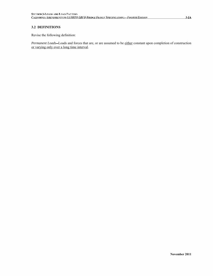
3.2 DEFINITIONS Revise the following definition: Permanent Loads Loads and forces that are, or are assumed to be either constant upon completion of construction or varying only over a long time interval.

November 2011
This page is intentionally left blank.

A
November 2011
3.2 DEFINITIONS Add the following definition:
Transient Loads Loads and forces that can vary over a short time interval relative to the lifetime of the structure.

November 2011
This page is intentionally left blank.

November 2011
Add the following notation:
TBaseConstr = base construction temperature

November 2011
This page is intentionally left blank.
November 2011
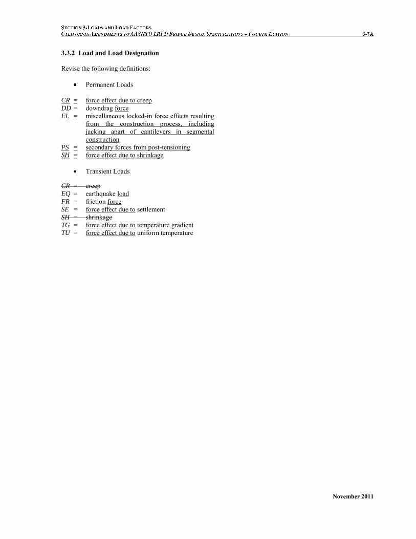
3.3.2 Load and Load Designation Revise the following definitions:
Permanent Loads
CR = force effect due to creep
DD = downdrag force EL = miscellaneous locked-in force effects resulting
from the construction process, including jacking apart of cantilevers in segmental construction
PS = secondary forces from post-tensioning SH = force effect due to shrinkage
Transient Loads
CR = creep EQ = earthquake load FR = friction force SE = force effect due to settlement SH = shrinkage TG = force effect due to temperature gradient TU = force effect due to uniform temperature

November 2011
3.4.1 Load Factors and Load Combinations Revise as follows: where:
i = load factors specified in Tables 1, and 2, and 3 Revise the 2nd Bullet as follows:
STRENGTH II—Load combination relating to the use of the bridge by Owner-specified special design vehicles, evaluation permit vehicles, or both without wind.
a) Load combination applies to superstructure design with load distribution factor tables in Articles 4.6.2.2, only.
b) Load combination used for superstructure design when the lever rule is called for by the tables in Article 4.6.2.2, for substructure design, or whenever a whole number of traffic lanes are is to be used. Live loads shall be placed in a maximum of two separate lanes chosen to create the most severe conditions.
C3.4.1 Revise the 3rd Paragraph as follows:
The permit vehicle should not be assumed to be the only vehicle on the bridge unless so assured by traffic control. See Article 4.6.2.2.4 regarding other traffic on the bridge simultaneously. The vehicular braking force shall not be included in this load combination. a) Multiple presence is already considered in the
load distribution factor tables in Articles 4.6.2.2. b) Multiple presence factors from Article 3.6.1.1.2
apply if the lever rule is used and in the case of substructure components.
November 2011
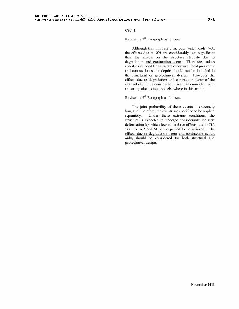
C3.4.1 Revise the 7th Paragraph as follows:
Although this limit state includes water loads, WA, the effects due to WA are considerably less significant than the effects on the structure stability due to degradation and contraction scour. Therefore, unless specific site conditions dictate otherwise, local pier scour and contraction scour depths should not be included in the structural or geotechnical design. However the effects due to degradation and contraction scour of the channel should be considered. Live load coincident with an earthquake is discussed elsewhere in this article. Revise the 9th Paragraph as follows:
The joint probability of these events is extremely low, and, therefore, the events are specified to be applied separately. Under these extreme conditions, the structure is expected to undergo considerable inelastic deformation by which locked-in-force effects due to TU, TG, and SE are expected to be relieved. The effects due to degradation scour and contraction scour, only, should be considered for both structural and geotechnical design.

November 2011
3.4.1 Load Factors and Load Combinations Revise the 12th Bullet as follows:
FATIGUE I –– Fatigue and fracture load combination relating to finite fatigue life and infinite fatigue life due to repetitive gravitational vehicular HL-93 truck live load and dynamic response under a single design truck having the axle spacing specified in Article 3.6.1.4.1. The load factors of 0.875 and 1.75 shall be used for finite fatigue life and infinite fatigue life, respectively.
C3.4.1 Revise the 17th Paragraph as follows:
The load factor applied to a single design truck, reflects a load level found to be representative of the truck population with respect to a large number of return cycles of stresses and to their cumulative effects in steel elements, components, and connections. Add the following after the 17th Paragraph:
Infinite fatigue life is the design concept used for higher traffic volume bridges. The maximum fatigue stress range is kept lower than the constant-amplitude fatigue threshold to provide a theoretically infinite fatigue life. Finite fatigue life is the design concept used for lower traffic volume bridges. The effective fatigue stress range is kept lower than the fatigue resistance, which is a function of cycles and details, to provide a finite fatigue life.
A comprehensive comparison study of fatigue load moments for steel girder bridges using the AASHTO LRFD Bridge Design Specifications (3rd Edition, 2004) compared to the AASHTO Standard
Specifications (17th Edition, 2002) was performed. From this parametric study, it is observed that the LRFD fatigue moments in an interior girder are about 60% and 20% less than that of the Standard, for finite fatigue life and infinite fatigue life, respectively.
To reflect past Caltrans’ infinite fatigue life
design practice using the AASHTO Standard
Specifications, the load factor of 0.875 together with a revised Fatigue Resistance Equation (6.6.1.2.5-1a), and the load factor of 1.75 together with a revised Fatigue Resistance Equation (6.6.1.2.5-1b) should be used for infinite fatigue life and infinite fatigue life in Fatigue I Limit State, respectively, for steel design. Those factors are based on the assumption that the maximum stress range is twice the live load stress range due to the passage of the fatigue truck specified in Article 3.6.1.2.2 with a constant spacing of 30.0 ft. between the 32.0-kips axles and derived by calibrating the LFRD fatigue design procedure to Caltrans past LFD design procedure. Figure C1 shows comparisons of fatigue resistance vs. number of cycles for a steel detail.

November 2011
3.4.1 Load Factors and Load Combinations Add the following after the 12th Bullet:
FATIGUE II –– Fatigue and fracture load combination relating to finite fatigue life due to repetitive Fatigue Permit truck live load and dynamic response under a single design truck having the axle spacing specified in Article 3.6.1.4.1.
Revise the 6th Paragraph as follows:
The larger of the two values provided for load factors of TU, CR, and SH shall be used for deformations and the smaller values for all other effects. For simplified analysis of substructures in the strength limit state, a value of 0.50 for may be used when calculating force effects, but shall be taken in conjunction with the gross moment of inertia in the columns or piers. When a refined analysis is completed for substructures in the strength limit state, a value of 1.0 for be used in conjunction with a partially cracked moment of inertia determined by analysis. For concrete substructures in the strength limit state, the value of 0.50 for and may similarly be used when calculating force effects in non-segmental structures, but shall be taken in conjunction with the gross moment of inertia in the columns or piers. For steel substructures, a value of 1.0 for and
Figure C3.4.1-1 Fatigue Resistance vs. Number of Cycles.
Add the following before the 18th Paragraph:
The load factor of 1.0 applied to a single design truck, reflects a load level found to be representative of the permit truck population with respect to a large number of return cycles of stresses and to their cumulative effects in elements, components, and connections.
Add the following after the 19th paragraph:
Load factors for earth loads have traditionally been set at about 2.0 for flexible culverts and 1.3 for rigid culverts. Since the uncertainty of earth load magnitude for flexible and rigid culverts should be similar, the earth load factor is set to 1.3; however, to preserve the overall safety at the same levels as historical specifications, an earth-load-installation factor is introduced later in these specifications. This factor may be adjusted based on field control of construction practices.
N
Finite life Infinite Life
Stand Spec & CA Amendment
LRFD Spec
LRFD Spec
Stand Spec
Finite life Infinite Life
3/1
N
AFn
nF
2 million
Finite life Infinite Life CA AmendmentN TH

November 2011
3.4.1 Load Factors and Load Combinations Revise Eq. 3.4.1-2 as follows: DC + DW + EH + EV + ES + WA + CR + SH + TG + EL + PS
(3.4.1-2)
C3.4.1 Add the following after the 25th Paragraph:
PS, CR, SH, TU and TG are superimposed deformations as defined in Article 3.12. Load factors for TU and TG are as shown in Table 1. Load factors for PS, CR, and SH, are as shown in Table 3. For prestressed members in typical bridge types, secondary prestressing, creep and shrinkage are generally designed for in the service limit state. In segmental structures, CR and SH are factored by P
for DC because some analytic methods for time-dependent effects in segmental bridges are nonlinear. The calculation of displacements for TU utilizes a factor greater than 1.0 to avoid undersizing joints, expansion devices, and bearings
November 2011
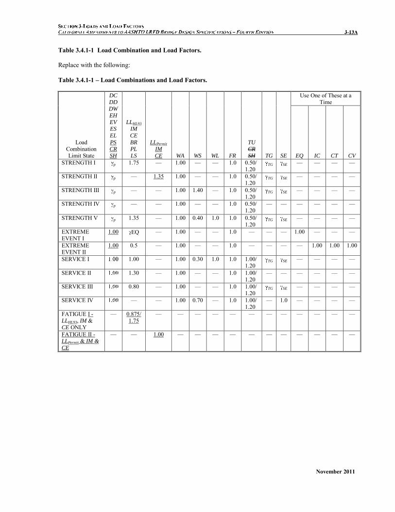
Table 3.4.1-1 Load Combination and Load Factors. Replace with the following: Table 3.4.1-1 – Load Combinations and Load Factors.
Load Combination Limit State
DC DD DWEH EV ES EL
PS CR SH
LLHL93 IM CE
BR PL LS
LLPermit IM CE WA WS WL FR
TU CR SH TG SE
Use One of These at a Time
EQ IC CT CV STRENGTH I p 1.75 — 1.00 — — 1.0 0.50/
1.20 TG SE — — — —
STRENGTH II p — 1.35 1.00 — — 1.0 0.50/1.20
TG SE — — — —
STRENGTH III p — — 1.00 1.40 — 1.0 0.50/1.20
TG SE — — — —
STRENGTH IV p
— — 1.00 — — 1.0 0.50/1.20
— — — — — —
STRENGTH V p 1.35 — 1.00 0.40 1.0 1.0 0.50/1.20
TG SE — — — —
EXTREME EVENT I
1.00 EQ — 1.00 — — 1.0 — — — 1.00 — — —
EXTREME EVENT II
1.00 0.5 — 1.00 — — 1.0 — — — — 1.00 1.00 1.00
SERVICE I 1.00 — 1.00 0.30 1.0 1.0 1.00/1.20
TG SE — — — —
SERVICE II 1.30 — 1.00 — — 1.0 1.00/1.20
— — — — — —
SERVICE III 0.80 — 1.00 — — 1.0 1.00/1.20
TG SE — — — —
SERVICE IV — — 1.00 0.70 — 1.0 1.00/1.20
— 1.0 — — — —
FATIGUE I - LLHL93, IM & CE ONLY
— 0.875/ 1.75
— — — — — — — — — — — —
FATIGUE II - LLPermit & IM & CE
— — 1.00 — — — — — — — — — — —
November 2011
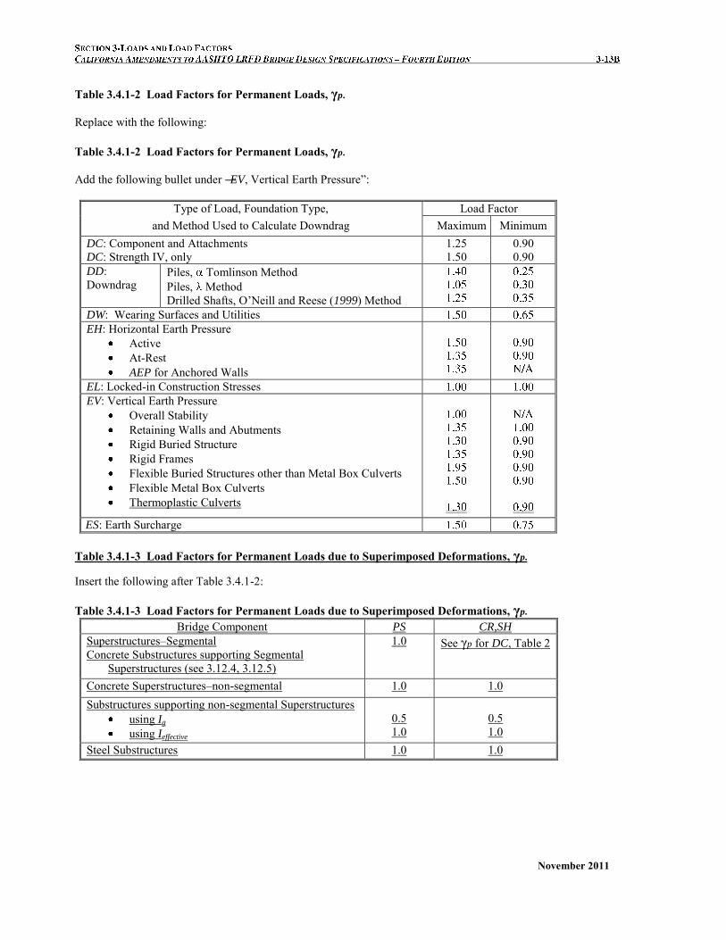
Table 3.4.1-2 Load Factors for Permanent Loads, γp. Replace with the following: Table 3.4.1-2 Load Factors for Permanent Loads, γp.
Add the following bullet under ―EV, Vertical Earth Pressure‖:
Type of Load, Foundation Type,
and Method Used to Calculate Downdrag Load Factor
Maximum Minimum DC: Component and Attachments DC: Strength IV, only
1.25 1.50
0.90 0.90
DD: Downdrag
Piles, Tomlinson Method Piles, Method Drilled Shafts, O’Neill and Reese (1999) Method
DW: Wearing Surfaces and Utilities EH: Horizontal Earth Pressure
Active At-Rest AEP for Anchored Walls
EL: Locked-in Construction Stresses EV: Vertical Earth Pressure
Overall Stability Retaining Walls and Abutments Rigid Buried Structure Rigid Frames Flexible Buried Structures other than Metal Box Culverts Flexible Metal Box Culverts
Thermoplastic Culverts
ES: Earth Surcharge
Table 3.4.1-3 Load Factors for Permanent Loads due to Superimposed Deformations, γp. Insert the following after Table 3.4.1-2: Table 3.4.1-3 Load Factors for Permanent Loads due to Superimposed Deformations, γp.
Bridge Component PS CR,SH
Superstructures–Segmental Concrete Substructures supporting Segmental
Superstructures (see 3.12.4, 3.12.5)
1.0 See γp for DC, Table 2
Concrete Superstructures–non-segmental 1.0 1.0 Substructures supporting non-segmental Superstructures
using Ig using Ieffective
0.5 1.0
0.5 1.0
Steel Substructures 1.0 1.0

November 2011
3.4.1 Load Factors and Load Combinations
Revise the last Paragraph as follows:
The load factor for live load in Extreme Event Load Combination I, EQ, shall be determined on a project-specific basis for operationally important structures. For ordinary standard bridges EQ = 0.
Add the following after the last Paragraph:
Engineering judgment shall be exercised when
applying blast loadings and when combining them with other loads.
Revise the 2nd to last Paragraph as follows:
Past editions of the Standard Specifications used EQ = 0.0. This issue is not resolved. The possibility of
partial live load, i.e., EQ < 1.0, with earthquakes should be considered. Application of Turkstra’s rule for combining uncorrelated loads indicates that EQ = 0.50 is reasonable for a wide range of values of average daily truck traffic (ADTT). Vehicular live loads have not been observed to be in-phase with the bridge structure during seismic events. Thus, the inertial effect of actual live loads on typical bridges is assumed to be negligible. Bridges that were seismically retrofitted without consideration of vehicular loads performed well during the 1994 Northridge earthquake.
Add the following after the last Paragraph:
Blast loads are considered an Extreme Event case
of loading. However, not enough information exists at the time of this writing (2006) to determine what other loads should be combined with blast loads and the appropriate load factors.

November 2011
This page is intentionally left blank.

November 2011
3.6.1.2.6 Distribution of Wheel Loads Through
Earth Fills
Revise the 2nd Paragraph as follows: In lieu of a more precise analysis, or the use of
other acceptable approximate methods of load distribution permitted in Section 12, where the depth of fill is 2.0 ft. or greater, wheel loads may be considered to be uniformly distributed over a rectangular area with sides equal to the dimension of the tire contact area, as specified in Article 3.6.1.2.5, and increased by either 1.15 times the depth of the fill in select granular backfill, or the depth of the fill in all other cases. The provisions of Articles 3.6.1.1.2 and 3.6.1.3 shall apply.
C3.6.1.2.6
Add the following after the 2nd Paragraph: Select granular backfill is not used for
embankments in California. The multiple presence factor should not be
applied when designing the top slab of culverts.

November 2011
This page is intentionally left blank.

November 2011
3.6.1.3.1 General
Add a 4th Bullet as follows: For negative moment between points of
contraflexure under a uniform load on all spans, and reaction at interior piers only, 100 percent of the effect of two design tandems spaced anywhere from 26.0 ft. to 40 ft. from the lead axle of one tandem to the rear axle of the other, combined with the design lane load specified in Article 3.6.1.2.4. The two design tandems shall be placed in adjacent spans to produce maximum force effects.
C3.6.1.3.1
Revise the 3rd Paragraph as follows: The notional design loads were based on the
information described in Article C3.6.1.2.1, which contained data on ―low boy‖ type vehicles weighing up to about 110 kip. Where multiple lanes of heavier versions of this type of vehicle are considered probable, consideration should be given to investigating negative moment and reactions at interior supports for pairs of the design tandem spaced from 26.0 ft. to 40.0 ft. apart, combined with the design lane load specified in Article 3.6.1.2.4. One hundred percent of the combined effect of the design tandems and the design lane load should be used. In California, side-by-side occurrences of the ―low boy‖ truck configuration are routinely found. This amendment is consistent with Article 3.6.1.2.1, will control negative bending serviceability in two-span continuous structures with 20-ft to 60-ft span lengths, and should not be considered a replacement for the Strength II Load Combination.
November 2011
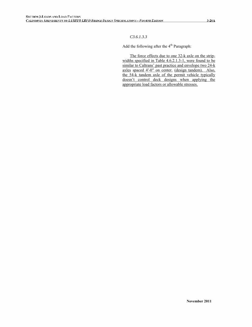
C3.6.1.3.3
Add the following after the 4th Paragraph: The force effects due to one 32-k axle on the strip-
widths specified in Table 4.6.2.1.3-1, were found to be similar to Caltrans’ past practice and envelope two 24-k axles spaced 4′-0″ on center. (design tandem). Also, the 54-k tandem axle of the permit vehicle typically doesn’t control deck designs when applying the appropriate load factors or allowable stresses.

November 2011
3.6.1.4.1 Magnitude and Configuration
Revise the 1st Paragraph as follows: For the Fatigue I limit state, tThe fatigue load
shall be one design truck or axles thereof specified in Article 3.6.1.2.2, but with a constant spacing of 30.0 ft. between the 32.0-kip axles.
For the Fatigue II limit state, the fatigue load shall be one Permit truck as specified in Figure 1.
C3.6.1.4.1
Add the following: The fatigue Permit Truck specified in Figure 1
represents the majority of permit trucks allowed in California.
Figure 3.6.1.4.1-1 Fatigue Permit Truck
3.6.1.4.2 Frequency
Add the following after the last Paragraph: In the absence of specific data, ADTT should be
taken as 2500 and 20, for the Fatigue I limit state and the Fatigue II limit state, respectively.
C3.6.1.4.2
Add the following after the last Paragraph:
ADTT of 2500 for the HS-20 fatigue truck has been successfully used for design of new structures and widenings in California. Based on the variation of sizes, weight and volumes of P5 through P13 Permit trucks operating in California, along with the growth rate of 1% within the 75-year design life; the volumes of P5 through P13 trucks are conservatively converted to an equivalent fatigue P9 permit truck with an ADTT
= 20.

November 2011
3.6.1.6 Pedestrian Loads Revise the 1st and 2nd Paragraphs as follows: A pedestrian load of 0.075 ksf shall be applied to
all sidewalks wider than 2.0 ft and considered simultaneously with the vehicular design live load in the vehicle lane. Where vehicles can mount the sidewalk, sidewalk pedestrian load shall not be considered concurrently. For a sidewalk that can be removed in the future, the vehicular live loads shall be applied at 1 ft from edge-of-deck for design of the overhang, and 2 ft from edge-of-deck for design of all other components.
Bridges intended for only pedestrian, equestrian, light maintenance vehicle, and/or bicycle traffic shall be designed for a live load of 0.085 ksf. in accordance with AASHTO’s LRFD Guide Specifications for the
Design of Pedestrian Bridges.
C3.6.1.6 Delete the 2nd Paragraph as follows: The conservatism in this Article reflects the
unpredictable nature of pedestrian load, which gains significance where it becomes a primary load.

November 2011
3.6.1.6 Pedestrian Loads
Delete the 3rd and 4th Paragraph: Where sidewalks, pedestrian, and/or bicycle
bridges are intended to be used by maintenance, and/or other incidental vehicles, these loads shall be considered in the design. The dynamic load allowance need not be considered for these vehicles.
Where vehicles can mount the sidewalk, sidewalk pedestrian load shall not be considered concurrently.
Add the following article 3.6.1.8:
3.6.1.8 Permit Vehicles
3.6.1.8.1 General
C3.6.1.6 Delete the 3rd Paragraph:
Snow removal and other maintenance vehicles
sometimes have access to pedestrian bridges. The slow speed of such vehicles justifies the omission of dynamic effects.
C3.6.1.8.1
Add the following: Permit design live loads, or P loads, are special
design vehicular loads. The weights and spacings of axles and wheels for the overload truck shall be as specified in Figure 3.6.1.8.1-1.
Figure 3.6.1.8.1-1 California P15 truck

November 2011
3.6.1.8.2 Application The permit design live loads shall be applied in
combination with other loads as specified in Article 3.4.1. Axles that do not contribute to the extreme force effect under consideration shall be neglected.
Dynamic load allowance shall be applied as specified in 3.6.2.
Multiple presence factors shall be applied as specified in Article 3.6.1.1.2. However, when only one lane of permit is being considered, the MPF for one loaded lane shall be 1.0.
3.6.2 Dynamic Load Allowance: IM
3.6.2.1 General Revise the 1st Paragraph as follows: Unless otherwise permitted in Articles 3.6.2.2 and
3.6.2.3, the static effects of the design truck, or design tandem, or permit vehicle other than centrifugal and braking forces, shall be increased by the percentage specified in Table 1 for dynamic load allowance….
Revise Table 3.6.2.1-1 as follows:
Table 3.6.2.1-1 Dynamic Load Allowance, IM.
Component IM
Deck Joints—All Limit States
75%
All Other Components Fatigue and Fracture
Limit State Strength II Limit State All Other Limit States
15%
25% 33%
C3.6.2.1 Revise the 4th Paragraph as follows: Field tests indicate that in the majority of highway
bridges, the dynamic component of the response does not exceed 25 percent of the static response to vehicles. This is the basis for dynamic load allowance with the exception of deck joints. However, the specified live load combination of the design truck and lane load, represents a group of exclusion vehicles that are at least 4/3 of those caused by the design truck alone on short- and medium-span bridges. The specified value of 33 percent in Table 1 is the product of 4/3 and the basic 25 percent. California removed the 4/3 factor for Strength II because a lane load isn’t a part of the design permit vehicle used. Furthermore, force effects due to shorter permit vehicles approach those due to the HL93. The HL93 tandem*1.33 + lane generally has a greater force effect than that due to the P15 on short-span bridges.

November 2011
C3.6.2.1
Revise the 6th Paragraph as follows: For heavy permit vehicles which have many axles
compared to the design truck, a reduction in the dynamic load allowance may be warranted. A study of dynamic effects presented in a report by the Calibration Task Group (Nowak 1992) contains details regarding the relationship between dynamic load allowance and vehicle configuration.

November 2011
This page is intentionally left blank.

November 2011
3.6.3 Centrifugal Forces: CE Revise the 1st Paragraph as follows:
For the purpose of computing the radial force or the overturning effect on wheel loads, the centrifugal effect on the live load shall be taken as the product of the axle weights of the design truck, design or tandem, or permit vehicle and the factor C, taken as:
Revise the 2nd Paragraph as follows:
Highway design speed shall not be taken to be less than the value specified in the current edition of the AASHTO publication, A Policy of Geometric
Design of Highways and Streets, the Caltrans Highway Design Manual (current edition), or as otherwise directed. The design speed for permit vehicles shall be 25 mph, maximum. Revise the 4th Paragraph as follows:
Centrifugal forces may shall be applied horizontally at a distance 6.0 ft. above the roadway surface. A load path to carry the radial force to the substructure shall be provided.
C3.6.3 Revise the 4th Paragraph as follows:
Centrifugal force also causes an overturning effect on the wheel loads when because the radial force is applied 6.0 ft. above the top of the deck. Thus, centrifugal force tends to cause an increase in the vertical wheel loads toward the outside of the bridge and an unloading of the wheel loads toward the inside of the bridge. The effect is more significant on structures with single column bents, but can be ignored for most applications. Superelevation helps to balance the overturning effect due to the centrifugal force and this beneficial effect may be considered. The effects due to vehicle cases with centrifugal force effects included should be compared to the effects due to vehicle cases with no centrifugal force, and the worst case selected.
November 2011
3.6.4 Braking Force: BR Revise the 2nd Paragraph as follows:
This braking force shall be placed in all design lanes which are considered to be loaded in accordance with Article 3.6.1.1.1 and which are carrying traffic headed in the same direction. These forces shall be assumed to act horizontally at a distance of 6.0 ft. above the roadway surface in either longitudinal direction to cause extreme force effects. All design lanes shall be simultaneously loaded for bridges likely to become one-directional in the future.
C3.6.4 Add a new last Paragraph as follows:
The overturning effect from braking is dependent on the number of axles and location of the drive train. This load may be applied at deck level with negligible effect on member sizes and quantities.

November 2011
3.7.5 Change in Foundations Due to Limit State for Scour Revise as follows:
The provisions of Article 2.6.4.4 shall apply. The potential effects due to the percentages of channel degradation or aggradation, contraction scour, and local scour shall be considered in the limit states shown in Table 1.
Table 3.7.5-1 Scour Conditions for Limit State Load Combinations
Limit State Degradation/Aggradation
Contraction Scour
Local Scour
Strength minimum 0% 0% 0%
maximum 100% 100% 50% Service minimum 0% 0% 0%
maximum 100% 100% 100%
Extreme Event I
minimum 0% 0% 0% maximum 100% 100% 0%
The consequences of changes in foundation
conditions resulting from the design Q100 base flood for scour shall be considered as specified in Section 2, and Articles 3.4.1 and 10.5 of the Specifications and California Amendments at strength and service limit states. The consequences of changes in foundation conditions due to scour resulting from the check flood for bridge scour and from hurricanes shall be considered at the extreme event limit states.
C3.7.5 Revise the 2nd Paragraph as follows:
Provisions concerning the effects of scour are given in Section 2. Scour per se is not a force effect, but by changing the conditions of the substructure it may significantly alter the consequences of force effects acting on structures. The design for fully-factored live loads in the scour conditions described for the strength limit state is in lieu of designing for an extreme event for flood.

November 2011
This page is intentionally left blank.

November 2011
3.8.1.2.2 Loads from Superstructures
Revise as follows:
Where the wind is not taken as normal to the
structure, the base wind pressures, PB, for various angles of wind direction may be taken as specified in Table 1. and shall be applied to a single place of exposed area. Longitudinal and transverse pressures shall be applied horizontally to the exposed surface area of the superstructure as seen in a side view. The skew angle shall be taken as measured from a perpendicular to the longitudinal axis. The wind direction for design shall be that which produces the extreme force effect on the component under investigation. The transverse and longitudinal pressures shall be applied simultaneously.

November 2011
This page is intentionally left blank.

November 2011
3.8.1.3 Wind Pressure on Vehicles: WL
Revise the 1st Paragraph as follows: When vehicles are present, the design wind
pressure shall be applied to both structure and vehicles. Wind pressure on vehicles may shall be represented by an interruptible, moving continuous force of 0.10 klf acting normal to, and 6.0 ft. above the roadway and shall be transmitted to the structure.
C3.8.1.3
Add the following after the 2nd Paragraph: Force effects due to this overturning couple of the
vehicle are negligible in structures on piers and multi-column bents, and can be ignored for most applications. If the load is applied at deck level rather than 6.0 ft. above the deck, the effect on member sizes is negligible for most applications.

November 2011
This page is intentionally left blank.

November 2011
3.10 EARTHQUAKE EFFECTS: EQ Delete article 3.10 in its entirety and replace with the following:
All provisions for seismic analysis, design and detailing of bridges contained in article 3.10 and elsewhere, shall be superseded by the Caltrans Seismic Design Criteria.

November 2011
This page is intentionally left blank.

November 2011
Revise as follows: 3.12 FORCE EFFECTS DUE TO SUPERIMPOSED DEFORMATIONS: TU, TG, SE, PS
3.12.2 Uniform Temperature Revise as follows:
The design thermal movement associated with a uniform temperature change shall may be calculated using Procedure A. or Procedure B below. Either Procedure A or Procedure B may be employed for concrete deck bridges having concrete or steel girders. Procedure A shall be employed for all other bridge types.
3.12.2.1 Temperature Range for Procedure A
The ranges of temperature shall be as specified in Table 1. The difference between the extended lower or upper boundary and the base construction temperature assumed in the design shall be used to calculate forces due to thermal deformation effects. Force effects shall be calculated using gross section properties and the lower value for TU.

November 2011
3.12.2.1 Temperature Range for Procedure A
Revise the 2nd Paragraph as follows: Unless otherwise specified, the minimum and
maximum temperatures specified in Table 1 shall be taken as TM and TM respectively, in Eqs. 1 and 2 3.12.2.3-1.
Add a 3rd Paragraph as follows:
The design thermal movement range for force
effects, shall be investigated for both of the following:
)( BaseConstrMaxDesignT TTL (Eq. 3.12.2.1-1)
)( BaseConstrMaxDesignT TTL (Eq. 3.12.2.1-2)
base construction temperature ( F)
expansion length (in.)
coefficient of thermal expansion (in./in./ F)
3.12.2.2 Temperature Range for Procedure B
Delete contents of the entire Article including Commentary and Figures.
C3.12.2.1
Add a 4th & 5th Paragraph as follows: Unless otherwise specified, the base construction
temperature may be taken as 60 F. In no case shall the design thermal movement range for force effects, ΔT, be investigated for a rise or fall of less than 35 F.
Expansion length is defined as the distance from the point of no thermal movement to the point under consideration (usually a joint or bent location).

November 2011
3.12.2.3 Design Thermal Movements Revise the 1st Paragraph as follows:
The design thermal movement range, T, for
joints and bearings, shall be used in conjunction with the higher value for γTU and depend upon the extreme bridge design temperatures defined in Article 3.12.2.1 or 3.12.2.2, and be determined as:
Add after the 1st Paragraph as follows:
The designer should make appropriate allowances for avoiding the possibility of hard surface contact between major structural components. Such conditions include the contact between slotted holes and anchor bolts, and between girders and abutments. Expansion joints and bearings should account for differences between the setting temperature and an assumed design installation temperature. In calculating ∆T for joints and bearings, ∆T shall be multiplied by the larger value shown for γTU in Table 3.4.1-1. Refer to Section 14 for additional design requirements for joints and bearings.

November 2011
This page is intentionally left blank.

November 2011
C3.12.4 Add a new last sentence as follows:
The load factor may be reduced to 1.0 if physical testing approved by the Owner is performed to establish material properties.
C3.12.5 Add a new last sentence as follows:
The load factor may be reduced to 1.0 if physical testing approved by the Owner is performed to establish material properties.
Add article 3.12.6.1
1. For predefined settlements used for
geotechnical design of foundations, that is 1.0″ for continuous spans and 2.0″ for simple spans: When geotechnical information indicates
that actual differential settlement is not expected to exceed 0.5″, settlement does not need to be considered in the structure analysis or design.
When geotechnical information indicates that differential settlement is likely to exceed 0.5″, force effects due to predefined settlements shall be included in the design of the superstructure, and the load factor SE shall be taken as 0.5 and 0.0.
2. When the Engineer performs refined analysis using nonlinear soil springs, the force effects due to settlement are directly included in the structural analysis. In that case settlement load factor SE shall be taken as 1.0 and 0.0.
Add the following:
3.12.7 Secondary Forces from Post-Tensioning, PS
The application of post-tensioned prestress forces on a statically indeterminate structure, produces reactions at the structure’s support and internal forces that are collectively called secondary forces.
C3.12.7
In frame analysis software, secondary forces are generally obtained by subtracting the primary prestress forces from the total prestressing.

November 2011
This page is intentionally left blank.
November 2011
3.14.11 Barge Collision Force on Pier
Delete the last Paragraph. The impact force for design barges larger than the standard hopper barge shall be determined by increasing the standard hopper barge impact force by the ratio of the larger barge’s width to the width of the standard hopper barge.

November 2011
This page is intentionally left blank.

November 2011
REFERENCES
Add References: AASHTO. 2009. Guide Specifications and Commentary for Vessel Collision Design of Highway Bridges, Second Edition, GSVCB-2. American Association of State Highway and Transportation Officials, Washington, DC.
AASHTO. 2009. Guide Specifications for Design of Pedestrian Bridges, Second Edition, GSDPB-2. American Association of State Highway and Transportation Officials, Washington, DC.

November 2011
This page is intentionally left blank.