Embed Size (px)
Citation preview

NASA Technical Memorandum 4453
X-15/HL-20 OperationsSupport Comparison
W. Douglas Morris
JUNE 1993

NASA Technical Memorandum 4453
X-15/HL-20 OperationsSupport Comparison
W. Douglas MorrisLangley Research CenterHampton, Virginia
Acknowledgments
This report brings together ideas and information from several
individualswithoutwhosecomments and insight the studywould
not have been possible. I wish to thank Charles N. Baker and
Jack Kolf of the Dryden Flight Research Facility for reviewing
this document and for providing information based on their
experiencesin theX-15 programcritical to completing the study.
Additionally, appreciation is extended toWally Eshleman of the
Lockheed Advanced Development Company whose discussions
onmethods of developing supportmanpowerhelpedtoformulate
the comparison approach used in this paper.

Summary
During the 1960's, the United States X-15 rocket-plane research program successfully demonstratedthe ability to support a reusable vehicle operatingin a near-space environment. The similarity of theproposed HL-20 lifting body concept in general size,weight, and subsystem composition to that of theX-15 provided an opportunity for a comparison of thepredicted support manpower and turnaround timeswith those experienced in the X-15 program. Infor-mation was drawn from both reports and discussionswith X-15 program personnel to develop comparativeoperations and support data. Based on the assump-tion of comparability between the two systems, thepredicted sta�ng levels, skill mix, and refurbishmenttimes of an operational HL-20 appear to be similarto those experienced by the X-15 for ground sup-port. However, safety, environmental, and supportrequirements have changed such that the HL-20 willface a di�erent operating environment than existed atEdwards during the 1950's and 1960's. Today's op-erational standards may impose additional require-ments on the HL-20 that will add to the maintenanceand support burden estimate based on the X-15analogy.
Introduction
The X-15 rocket-plane program is arguably one ofthe most successful ight research programs to date.Conceived in the early 1950's, this rocket poweredaircraft began ight testing in the late 1950's andconcluded in 1968 after 199 ights. The ights werestaged from a B-52 aircraft that was used to carryit to launch altitude. The X-15 set speed and alti-tude marks yet to be surpassed by any other aircraft.While much of the focus of the program was on thescienti�c and engineering discoveries that increasedour knowledge of high-speed aeronautics and tech-nology, the processes needed to support space ightof later reusable spacecraft were being developed bythose responsible for servicing the X-15. A number ofpapers have been written that address the X-15 op-erational processing (Hoey and Day 1962; Love andPalmer 1961; Love and Young 1965, 1966, and 1967;Row and Fischel 1963). However, detailed informa-tion about speci�c support operations such as themaintenance crew size and skill mix was not gen-erally covered by these reports. The source of thatinformation is retained, primarily, in the memories ofthose who were a part of the X-15 program. Some ofthe support methods developed during the programappear to be the basis for techniques still in use inthe Space Shuttle program.
The HL-20 represents a recent study of a liftingbody concept designed to complement the Shuttleas a means to support Space Station crew rotationson an operational basis (Piland 1990). Requiredto be launched into orbit by an expendable launchvehicle, the HL-20 would itself be reusable andrequire a maintenance program to prepare it forre ight. Contracted studies with Rockwell Inter-national Corporation (Ehrlich 1991) and later byLockheed Advanced Development Company (Per-sonal Launch System Feasibility Study under NASAContract NAS1-18570) further de�ned the initialNASA concept in terms of subsystem requirementsand provided initial estimates of the manpower andprocessing times required based on aircraft and air-line maintenance concepts. From these estimates acomparison can be drawn between the X-15 and theHL-20 concept to assess the potential support re-quirements of this new system.
The proposed HL-20 design has many similaritiesto the X-15 (�gs. 1 and 2, table I). They are similarin size and weight, they are both staged o� of launchvehicles, they both consist of a eet of 3 aircraft, andthey have similar subsystem types, including reac-tion control, avionics, thermal protection, etc. The ight program for the X-15 lasted over 9 years andincluded 199 ights. The HL-20 ight program isanticipated to include 143 ights over a 20-year pe-riod. Over the life of the X-15 program, the averageturnaround time for this research aircraft was 44 cal-endar days, including mission and delay times (de-rived from Miller 1983, see appendix). Turnaroundtime for the HL-20 is predicted to be 46 calendardays, including a 3-day mission.
This paper presents a comparison of the predictedsupport requirements for the HL-20 with the histor-ical support requirements of the X-15 in terms ofmanpower and turnaround time. The X-15 require-ments were established by drawing from past reportsand from interviews with those with �rsthand main-tenance and support operations experience on thevehicle.
Nomenclature
ac alternating current
ACC advanced carbon carbon
AFRSI advanced exible reusable surfaceinsulation
Ag-Zn silver zinc
APU auxiliary power unit

. . . . . . . . . 50
. . . . . . . . . 22
. . . . . . . . . 15 000
. . . . . . . . . 33 300
Length, ft Span, ft Dry weight, lb Gross weight, lb
Figure 1. X-15.
A&P airframe and powerplant
BITE built-in test equipment
CO2 carbon dioxide
dc direct current
ECLSS environmental control and lifesupport system
GN&C guidance, navigation, and control
GSE ground support equipment
HTP high-temperature performance
HUD head-up display
KSC Kennedy Space Center
LiOH lithium hydroxide
LOX liquid oxygen
MMH monomethyl hydrazine
NDE nondestructive evaluation
N2O4 nitrogen tetroxide
OMS orbital maneuvering system
RCS reaction control system
STS space transportation system
TPS thermal protection system
TVC thrust vector control
Processing Descriptions
X-15 Turnaround Process
Turnaround time is considered the length of timefrom the completion of one ight to the completionof the next ight, including ground processing andmission time. The refurbishment or maintenancetime, which is a subset of the turnaround time, ismeasured from the time the vehicle returns from ight to when it is ready for the next ight (Love andYoung 1967). Refurbishment time is dependent onthe maintenance, instrumentation, and modi�cationrequirements; the ight schedule; and the size ofthe support crew. During the mid-1960's the X-15program was achieving a ight rate of over 30 peryear for the 3-aircraft eet. According to discussionswith Charles N. Baker, former X-15 crew chief at theDryden Flight Research Facility, in this time periodthe support crew for each aircraft typically consistedof 12 technicians per shift, 2 shifts per day, 5 daysper week. (In the last 2 years of the program, whenthe ight rate was reduced, a single support crew
2
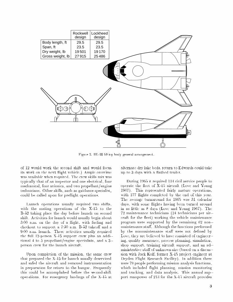
Rockwell design 29.5 23.5
19 501 27 915
Body length, ft Span, ft Dry weight, lb Gross weight, lb
Lockheed design29.5 23.5
19 170 25 486
Figure 2. HL-20 lifting body general arrangement.
of 12 would work the second shift and would focusits work on the next ight vehicle.) Ample overtimewas available when required. The crew skills mix wastypically that of an inspector and one electrical, fourmechanical, four avionics, and two propellant/enginetechnicians. Other skills, such as guidance specialist,could be called upon for pre ight operations.
Launch operations usually required two shifts,with the mating operations of the X-15 to theB-52 taking place the day before launch on secondshift. Activities for launch would usually begin about3:00 a.m. on the day of a ight, with fueling andcheckout to support a 7:30 a.m. B-52 takeo� and a9:00 a.m. launch. These activities usually requiredthe full 12-person X-15 support crew plus an addi-tional 4 to 5 propellant/engine specialists, and a 3-person crew for the launch aircraft.
Upon completion of the mission, the same crewthat prepared the X-15 for launch usually deservicedand safed the aircraft and removed instrumentationin preparation for return to the hangar. Frequentlythis could be accomplished before the second-shiftoperations. For emergency landings of the X-15 at
alternate dry lake beds, return to Edwards could takeup to 3 days with a atbed trailer.
During 1965 it required 134 civil service people tooperate the eet of X-15 aircraft (Love and Young1967). This represented fairly mature operations,with 177 ights completed by the end of this year.The average turnaround for 1965 was 31 calendardays, with some ights having been turned aroundin as little as 8 days (Love and Young 1967). The72 maintenance technicians (24 technicians per air-craft for the eet) working the vehicle maintenanceprogram were supported by the remaining 62 non-maintenance sta�. Although the functions performedby the nonmaintenance sta� were not de�ned byLove, they are believed to have consisted of engineer-ing, quality assurance, process planning, simulation,shop support, training aircraft support, and an ad-ministrative sta� of unknown size (based on a discus-sion with Jack Kolf, former X-15 project engineer atDryden Flight Research Facility). In addition therewere 79 people performing mission analysis functions,which included ight planning, mission monitoringand tracking, and data analysis. This annual sup-port manpower of 213 for the X-15 aircraft provides
3

Table I. X-15 and HL-20 Subsystems for Rockwell and LockheedDesigns
Parameter X-15 HL-20 Rockwell HL-20 Lockheed
Body|primary Titanium and Inconel X Aluminum 2219/2024 Aluminum 2219/2024
structure, Inconel X skin
Body|upper panels Inconel X skin Aluminum alloy honeycomb Aluminum alloy honeycomb
Fins/wings Titanium and Inconel X Graphite polyimide Titaniumhoneycomb
structure, Inconel X skin (with TPS) (with TPS)
Heat shield structure Inconel X Graphite polyimide Titanium isogrid (segmented)
TPS|bottom Ablative, resin-based glass HTP6 (direct bond) HTP6 (direct bond)
bead powder (limited
use/X-15A-2)
TPS|upper Ablative, resin-based glass AFRSI blanket (direct bond) AFRSI blanket (direct bond)
bead powder (limited
use/X-15A-2)
TPS|leading edges Ablative Advanced carbon carbon Advanced carbon carbon
Landing gear Nonsteerable nose wheel (2), All electric �ghter gear All electric �ghter gear
main gear skids (F-5 modi�ed)
Main propulsion Anhydrous ammonia/LOX, None None
helium purge
RCS propulsion Hydrogen peroxide, 12 nozzles, Hydrogen peroxide MMH/N2O4(satellite vernier
40 to 100 lbf thrusters)
OMS propulsion None Hydrogen peroxide/JP-4 MMH/N2O4(STS RCS vernier
thrusters)
Prime power 2 APU's driven by hydrogen Rechargeable Ag-Zn batteries Rechargeable Ag-Zn batteries
peroxide for electrical
and hydraulics
Electrical 115 volt ac dc dc
Actuators Hydraulic Electromechanical/ Electromechanical
electrohydraulic
Avionics State-of-the-art and advanced State of the art State of the art
systems (autonomous/BITE/ (autonomous/BITE/
HUD/etc.) HUD/etc.), eliminate micro-
wave landing system
ECLSS Liquid nitrogen for temperature Water loop; solid amine CO2 LiOH canisters, ammonia
control of suit, cockpit, and removal system boiler, water loop
instrumentation
Personnel accommodations Full pressure suit Apollo-type waste Apollo-type waste
management management
Recovery/abort Ejection seat Apollo-type chutes, solid abort Apollo-type chutes/solid abort
motors motors with TVC
a basis for comparison with HL-20 spacecraft sup-port requirements. In addition to the 213 peopleproviding direct support, the X-15 program required112 people to support the B-52 carrier aircraft, over-haul the XLR99 rocket engine, and provide base sup-port, bringing the total annual manpower require-ments to support the X-15 program to 325 people.
HL-20 Turnaround Process
The HL-20 refurbishment process is made upof the sa�ng and deservicing process, the main-
tenance process, and the integration and launchprocess. The refurbishment time and manpowerare assumed to be driven primarily by the mainte-nance requirements for the vehicle. In the RockwellHL-20 study (Ehrlich 1991) the turnaround time andmanpower were derived from comparisons with his-torical aircraft systems maintenance records and ad-justed to account for Shuttle support experience ona subsystem by subsystem basis. From this informa-tion the number of man-hours required to performcorrective and preventive maintenance was derived
4
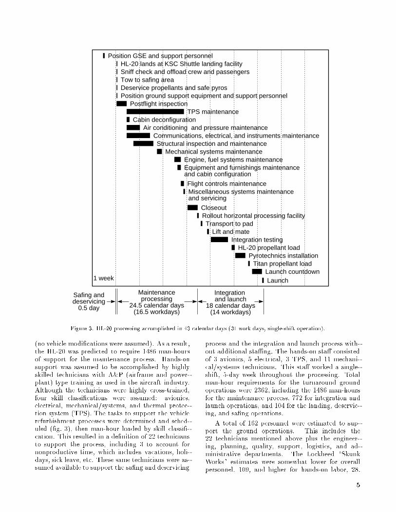
Launch
Postflight inspectionTPS maintenance
Cabin deconfigurationAir conditioning and pressure maintenance
Communications, electrical, and instruments maintenanceStructural inspection and maintenance
Mechanical systems maintenanceEngine, fuel systems maintenanceEquipment and furnishings maintenance and cabin configuration
Flight controls maintenanceMiscellaneous systems maintenance and servicing
CloseoutRollout horizontal processing facility
Transport to padLift and mate
Integration testingHL-20 propellant load
Pyrotechnics installationTitan propellant load
Launch countdown
Maintenance processing
24.5 calendar days (16.5 workdays)
Integration and launch
18 calendar days (14 workdays)
Safing and deservicing
0.5 day
1 week
Position GSE and support personnel
Sniff check and offload crew and passengersTow to safing areaDeservice propellants and safe pyrosPosition ground support equipment and support personnel
HL-20 lands at KSC Shuttle landing facility
Figure 3. HL-20 processing accomplished in 43 calendar days (31 work days, single-shift operation).
(no vehicle modi�cations were assumed). As a result,the HL-20 was predicted to require 1486 man-hoursof support for the maintenance process. Hands-onsupport was assumed to be accomplished by highlyskilled technicians with A&P (airframe and power-plant) type training as used in the aircraft industry.Although the technicians were highly cross-trained,four skill classi�cations were assumed: avionics,electrical, mechanical/systems, and thermal protec-tion system (TPS). The tasks to support the vehiclerefurbishment processes were determined and sched-uled (�g. 3), then man-hour loaded by skill classi�-cation. This resulted in a de�nition of 22 techniciansto support the process, including 3 to account fornonproductive time, which includes vacations, holi-days, sick leave, etc. These same technicians were as-sumed available to support the sa�ng and deservicing
process and the integration and launch process with-out additional sta�ng. The hands-on sta� consistedof 3 avionics, 5 electrical, 3 TPS, and 11 mechani-cal/systems technicians. This sta� worked a single-shift, 5-day week throughout the processing. Totalman-hour requirements for the turnaround groundoperations were 2362, including the 1486 man-hoursfor the maintenance process, 772 for integration andlaunch operations, and 104 for the landing, deservic-ing, and sa�ng operations.
A total of 162 personnel were estimated to sup-port the ground operations. This includes the22 technicians mentioned above plus the engineer-ing, planning, quality, support, logistics, and ad-ministrative departments. The Lockheed \SkunkWorks" estimates were somewhat lower for overallpersonnel, 109, and higher for hands-on labor, 28.
5

0
300
250
200
150
100
50
Tur
naro
und
time,
cal
enda
r da
ys594
0 18016014012010080
Number of flights
604020
92% of flights used to form frequency distribution
200
Figure 4. X-15 ights ordered by turnaround time.
The lower ratio of support personnel to hands-onsta�ng is based on Lockheed's contracted logisticssupport experience.
In addition to the ground support operations,Rockwell estimated a sta� of 205 personnel were re-quired to support mission operations. These ight-speci�c functions consist of mission planning, simu-lation, crew activity planning, and real-time supportfor each ight of the HL-20. Mission support per-sonnel that work generically on all ights and thesupport sta� are not accounted for here. Thus thetotal supporting sta� comparable to the 213 peoplein the X-15 program would be 367 for the HL-20 dur-ing mature operations.
Comparison and Discussion
Ideally one comparison between the support re-quirements of the X-15 and HL-20 programs shouldbe in terms of the maintenance burden for each ve-hicle subsystem. The maintenance burden, as usedin this report, is the man-hours required for bothscheduled and unscheduled maintenance in supportof the typical turnaround operation. The mainte-nance burden is a function of the design, the fail-ure rate, the mission time, and the maintenance pol-icy and can be used to de�ne the average crew sizeand/or processing time required for the turnaround
operation. Unfortunately, this information was notavailable for the X-15. However, by using the X-15 ight histories, an estimate was derived of the over-all X-15 maintenance man-hour burden comparableto an HL-20 man-hour estimate. This was achievedby using the previously presented ground supportcrew size, as de�ned by Baker, with the time re-quired for vehicle servicing and maintenance of fail-ures. This maintenance/service time was estimatedfrom the total turnaround time for each ight basedon the ight histories in Miller (1983). (See appen-dix for ight histories of the three aircraft.) Theturnaround times were plotted in order of increasingtimes and are shown in �gure 4. These turnaroundtimes include not only scheduled and unscheduledmaintenance, but also aircraft modi�cations, missionaborts, mission delays, and schedule drivers. In anattempt to capture only the required maintenanceburden that would be re ected by these turnaroundtimes, the 13 longest were excluded from the analysisalong with the turnaround times for the initial ightof each aircraft. These 13 ights were more likely tohave included some major modi�cations and repairor extensive weather and schedule delays. (Based on ights from Sept. 1961 to July 1965, the delays dueto weather, aircraft and experiment modi�cations,and miscellaneous causes represent about 35 percentof the delay times (Love and Young 1966).) There
6

appears to be a clear change in processing times atabout the 106-day point. It was felt that the re-maining processing times, representing 92 percent ofall ights, were more representative of the processingactivities, even though these still include some of themore typical delays due to weather, schedule, etc.
From the description given of the X-15 turn-around process, it appears that the equivalent of1 workday was usually devoted to the integration andmission of the X-15. In an attempt to compare onlythe maintenance times, a day was subtracted fromeach of the turnaround times. A frequency distribu-tion was then developed based on 7-day centers and isshown in �gure 5. The results indicate that the mostfrequently experienced maintenance processing timerequired for the X-15 was about 13 calendar days, or9 workdays. This should be representative of thosemaintenance processings that consist primarily of therepair and checkout operations. The longer timesshown in �gure 5 would be more likely to includevehicle modi�cations and any delays due to aborts,weather, schedule, etc. This is consistent with re-sults observed during 1964 and 1965, when only oneturnaround in three was accomplished without de-lays or aborts (Love and Young 1967). The main-tenance burden can then be computed based on thederived processing time. Thus, the results shouldbe representative of the processing time and main-tenance manpower required for the X-15 when min-imal modi�cations or scheduled delays occur duringturnaround.
12010080604020Maintenance processing time, calendar days
0
45
40
35
30
25
20
15
10
5
Num
ber
of fl
ight
s Predicted maintenance processing time for the HL-20
Most frequent maintenance processing time for X-15 flights
Statistical summary Mode Mean Std. dev. (Based on 183 observations)
. . . . . . . . . . . . . . 13.0 . . . . . . . . . . . . . . 29.2
. . . . . . . . . . 22.9
Figure 5. X-15maintenance processing time histogram.
Using the 24 technicians (2 shifts of 12) overthis derived 9-workday period yields 1728 man-hours
available to satisfy the maintenance burden for theX-15. Removing 12 percent of the man-hours thattypically are required for nonproductive time leaves1520 productive man-hours. The maintenance bur-den was then assumed equal to the productive man-hours. By comparison, the maintenance burden forthe HL-20, as de�ned by Rockwell, is 1486 man-hours (Ehrlich 1991). Based on the Rockwell-de�nedsta�ng level, 2904 man-hours are available to achievethe total HL-20 refurbishment operations over the24.5 calendar days typically required (16.5 work-days) during the turnaround process. The Lockheed-de�ned burden for the maintenance is 1718 man-hours (the speci�c time period for maintenanceoperations was not de�ned). These �ndings aresummarized in table II.
Although the maintenance processing time esti-mated for the HL-20 is greater than that experiencedby the X-15 and the man-hours required to satisfythe maintenance burden less, these results probablylie within the uncertainty band associated with theassumptions made in the derivation of these results.The longer mission length for the HL-20 could be ex-pected to generate higher maintenance requirementsthan if it ew the shorter duration X-15 mission.The additional time available for the HL-20 process-ing provides a margin of 1486 additional man-hoursthat can be applied should the actual maintenancerequirements exceed the predicted burden. Based onthe assumption of design comparability, the HL-20support estimate would appear to be comparable tothat experienced by the X-15.
The integration and launch operations were ex-cluded from this comparison. With the X-15 re-quiring only 1 day for this process and the HL-20requiring 14 workdays, clearly the integration andlaunch process is driven by di�erent requirements forthese two systems. For example, the HL-20 requiresa launch escape system that must be integrated withthe launch vehicle, whereas the X-15 did not.
Another method of comparison between the twoprograms is based on the total available man-hoursto support the total turnaround process (sa�ng, de-servicing, maintenance, integration, and launch).This involves using the typical X-15 processing timesthat were achieved. Shorter turnaround times couldhave been achieved (and frequently were), but theschedule may not have required it. These compar-isons are a function of the ight rate.
During 1965 and 1966, the X-15 eet was ownat a rate of over 30 ights per year (no ights fromNov. 4, 1965 to May 6, 1966) representing an averageturnaround time of 36.5 calendar days (26 workdays)
7

Table II. Operations Support Requirements for X-15 and HL-20
Parameter X-15 HL-20 Rockwell HL-20 Lockheed
Length, ft 50 29.5 29.5
Span, ft 22 23.5 23.5
Dry weight, lb 15000 19501 19170
Gross weight, lb 33300 27915 25486
Flight crew and passengers 1 10 8
Technology level Advanced Near term Near term
Mission types Research Operational Operational
Hands-on crew per turnaround 24 22 28
Skills Electrical (1) Electrical (5) Avionics (9)
Mechanical (3) Mechanical/systems (11) Systems (11)
Avionics (4) Avionics (3) NDE (3)
Propellant/engine (2) TPS (3) Inspector (5)
Crew chief (1)
Inspector (1)
Maintenance hands-onman-hours 1520/1728 (based on productive 1486/2904 (based on 1718/N/A(based on
permaintenance processing man-hours/total man-hours, comparable aircraft comparable Shuttle
(burden/available) 13 workdays) systems/16.5 workdays) systems/not de�ned)
Hands-onman-hours available 4992 (includes mission, 5456 (excludesmission, 6720 (excludesmission,
per turnaround (safe, maintain, based on 26 workdays) based on 31 workdays) based on 30 workdays)
integrate, and launch)
Flight rate per year 10 (based on 1 aircraft) 8 8
Fleet size 3 3 3
Support sta� (includes hands-on) 134 (supports 30 ights/yr) 162 109
Mission operations and analysis 79 205 (excludes all- ight and Not addressed
support non ight support sta�)
Launch vehicle support Excluded Excluded Excluded
for each aircraft (or a ight rate of 10 ights per yearfor each aircraft). This represents 4992 man-hoursavailable from the hands-on support crew for eachmission.
By comparison, the Rockwell analysis predicts theHL-20 will require a hands-on sta� of 22 technicians,working 1 shift, 5-day weeks, 43 calendar days(31 workdays) to receive, safe, refurbish, integrate,and prepare it for launch. This represents 5456 man-hours per mission. This analysis was based on8 ights per year. For the same ight rate, the Lock-heed analysis resulted in 6720 man-hours based onusing 28 technicians over 42 calendar days to sup-port the turnaround process. (This information waspresented at the HL-20 PLS Feasibility AssessmentContractor Review, Dec. 10{11, 1991.) Their crewmakeup and size were dictated by skill requirementsand vary slightly from the hands-on crew require-ments of the Rockwell study. For example, Lockheedconsiders the NDE (nondestructive evaluation) tech-nicians and inspectors to be a part of the hands-oncrew, whereas Rockwell considered these as support
functions. The X-15 program also used NDE person-nel but in a support role. Because of the low ightrate, the support man-hours are spread over a longerperiod than the maintenance burden would requireto process the HL-20.
The similarities in subsystems, support sta�s, andoverall processing times would imply a certain de-gree of comparability between the support requiredfor the two vehicles. But, there are also a numberof di�erences that need to be noted. Technologiesused by the X-15 represented cutting-edge technolo-gies at that time. They included Inconel skin, ti-tanium structure, reaction control systems (RCS),highly sophisticated throttleable rocket power, in-tegrated control systems, and ight simulators us-ing analog technology. In addition these technologieswere own in altitude and speed regimes not previ-ously explored. It might reasonably be expected thatthe failure rates and repair times experienced withthese systems would be higher than in an operationalprogram where the technologies were more state ofthe art. Technologies chosen for the HL-20 represent
8

existing and near-term technologies (ceramic tiles,ACC, blanket TPS, titanium or aluminum structure,hydrogen peroxide RCS, GN&C, etc.). The main-tenance concept for the X-15 represented a supportenvironment for an experimental program that in-volved development, modi�cations, and ying exper-imental systems, which also had to be maintained.The HL-20 is to have a repeatable, speci�c mission toperform, for which there should be no modi�cationsor experimental packages to complicate the mainte-nance function. Therefore, a more operational main-tenance environment should be applicable.
Charles Baker and Jack Kolf of the X-15 pro-gram have added some additional cautions to thesecomparisons. Charles Baker indicated that a two-shift operation may be required for the HL-20 in-stead of the one shift proposed. This could createtwo shifts whose total manpower requirements wouldbe slightly larger than those required for single-shiftoperations in order to meet minimum skill require-ments on each shift. Jack Kolf indicates that theuse of a thermal protection system in the HL-20that is robust and easily penetrated for access to thesubsystems may represent the di�erence between be-ing able to perform aircraft-like maintenance on theHL-20 or requiring the much longer process times as-sociated with the Space Shuttle.
It is interesting to note that based on the �rst7 years of the X-15 ight experience, Love and Youngbelieved that the turnaround time for a similar typeof vehicle without the research role and associatedinstrumentation might be as low as 15 days (Loveand Young 1967). This estimate would apply to aprototype or an initial production model of a reusablevehicle.
An additional consideration is the support envi-ronment in which the HL-20 will operate. It will mostlikely be di�erent from that of the X-15 in the 1950'sand 1960's. The types of safety and environmentalrules that exist today were essentially nonexistent atthat time. For example, more stringent requirementsare placed on the handling and disposal of hazardousmaterials today. Along with this comes new operat-ing procedures and additional training requirements.Work procedural changes mean additional oversightin safety and quality assurance. These would cer-tainly add to the support requirements if the X-15program were repeated today.
Concluding Remarks
The X-15 program successfully demonstrated theability to support a reusable vehicle operating in anear-space environment with a ight rate and sup-port sta� similar to that predicted for the HL-20.Given an operating environment similar to that ex-perienced by the X-15, subsystem comparability, anda similar support environment, the HL-20 mainte-nance and support crew complement should be ableto achieve the turnaround time predicted for theHL-20. The HL-20 will, however, be operating in adi�erent environment than existed at Edwards AFBduring the 1950's and 1960's. Today's operating en-vironment will likely impose additional requirementson the HL-20 that will add to the maintenance andsupport burden predicted by using the X-15 analogy.
NASALangley Research Center
Hampton, VA 23681-0001
April 22, 1993
9

Appendix A
X-15 Turnaround Times
Table A1. X-15 Turnaround Times (Miller 1983)
All aircraft: No. 1 aircraft: No. 2 aircraft: No. 3 aircraft:
(199 ights) (81 ights) (53 ights) (65 ights)
Flight Aircraft Flight Flight Flight
no. Date no. Days no. Date Days no. Date Days no. Date Days
1 6/8/59 1 1 6/8/59 2 9/17/59 46 12/20/61
2 9/17/59 2 101 5 1/23/60 229 3 10/17/59 30 48 1/17/62 28
3 10/17/59 2 30 9 3/25/60 62 4 11/5/59 19 49 4/5/62 78
4 11/5/59 2 19 12 4/13/60 19 6 2/11/60 98 51 4/20/62 15
5 1/23/60 1 79 13 4/19/60 6 7 2/17/60 6 57 6/12/62 53
6 2/11/60 2 19 14 5/6/60 17 8 3/17/60 29 58 6/21/62 9
7 2/17/60 2 6 15 5/12/60 6 10 3/29/60 12 62 7/17/62 26
8 3/17/60 2 29 16 5/19/60 7 11 3/31/60 2 65 8/2/62 16
9 3/25/60 1 8 18 8/4/60 77 17 5/26/60 56 67 8/14/62 12
10 3/29/60 2 4 19 8/12/60 8 26 11/15/60 173 71 10/4/62 51
11 3/31/60 2 2 20 8/19/60 7 28 11/22/60 7 73 10/23/62 19
12 4/13/60 1 13 21 9/10/60 22 30 12/6/60 14 75 12/14/62 52
13 4/19/60 1 6 22 9/23/60 13 34 3/7/61 91 76 12/20/62 6
14 5/6/60 1 17 23 10/20/60 27 35 3/30/61 23 77 1/17/63 28
15 5/12/60 1 6 24 10/28/60 8 36 4/21/61 22 79 4/18/63 91
16 5/19/60 1 7 25 11/4/60 7 37 5/25/61 34 81 5/2/63 14
17 5/26/60 2 7 27 11/17/60 13 38 6/23/61 29 82 5/14/63 12
18 8/4/60 1 70 29 11/30/60 13 40 9/12/61 81 84 5/29/63 15
19 8/12/60 1 8 31 12/9/60 9 41 9/28/61 16 85 6/18/63 20
20 8/19/60 1 7 32 2/1/61 54 43 10/11/61 13 87 6/27/63 9
21 9/10/60 1 22 33 2/7/61 6 45 11/9/61 29 90 7/19/63 22
22 9/23/60 1 13 39 8/10/61 184 53 5/8/62 180 91 8/22/63 34
23 10/20/60 1 27 42 10/4/61 55 55 6/1/62 24 94 11/7/63 77
24 10/28/60 1 8 44 10/17/61 13 60 6/29/62 28 96 11/27/63 20
25 11/4/60 1 7 47 1/10/62 85 63 7/19/62 20 99 1/16/64 50
26 11/15/60 2 11 50 4/19/62 99 66 8/8/62 20 101 2/19/64 34
27 11/17/60 1 2 52 4/30/62 11 68 8/20/62 12 102 3/13/64 23
28 11/22/60 2 5 54 5/22/62 22 69 8/29/62 9 106 5/12/64 60
29 �11/30/60 1 8 56 6/7/62 16 70 9/28/62 30 108 5/21/64 9
30 12/6/60 2 6 59 6/27/62 20 72 10/9/62 11 111 7/8/64 48
31 12/9/60 1 3 61 7/16/62 19 74 11/9/62 31 112 7/29/64 21
32 2/1/61 1 54 64 7/26/62 10 109 6/25/64 594 113 8/12/64 14
33 2/7/61 1 6 78 4/11/63 259 114 8/14/64 50 115 8/26/64 14
34 3/7/61 2 28 80 4/25/63 14 118 9/29/64 46 116 9/3/64 8
35 3/30/61 2 23 83 5/15/63 20 121 11/30/64 62 117 9/28/64 25
36 4/21/61 2 22 86 6/25/63 41 127 2/17/65 79 120 10/30/64 32
37 5/25/61 2 34 88 7/9/63 14 131 4/28/65 70 122 12/9/64 40
38 6/23/61 2 29 89 7/18/63 9 132 5/18/65 20 124 12/22/64 13
39 8/10/61 1 48 92 10/7/63 81 137 6/22/65 35 125 1/13/65 22
40 9/12/61 2 33 93 10/29/63 22 139 7/8/65 16 126 2/2/65 20
41 9/28/61 2 16 95 11/14/63 16 141 8/3/65 26 130 4/23/65 80
42 10/4/61 1 6 97 12/5/63 21 146 9/2/65 30 134 5/28/65 35
�Values corrected based onHallion 1984.
10

Table A1. Continued
All aircraft: No. 1 aircraft: No. 2 aircraft: No. 3 aircraft:
(199 ights) (81 ights) (53 ights) (65 ights)
Flight Aircraft Flight Flight Flight
no. Date no. Days no. Date Days no. Date Days no. Date Days
43 10/11/61 2 7 98 1/8/64 34 155 11/3/65 62 135 6/16/65 19
44 10/17/61 1 6 100 1/28/64 20 158 5/18/66 196 138 6/29/65 13
45 11/9/61 2 23 103 3/27/64 59 159 7/1/66 44 140 7/20/65 21
46 12/20/61 3 41 104 4/8/64 12 162 7/21/66 20 143 8/10/65 21
47 1/10/62 1 21 105 4/29/64 21 164 8/3/66 13 145 8/26/65 16
48 1/17/62 3 7 107 5/19/64 20 167 8/12/66 9 148 9/14/65 19
49 4/5/62 3 78 110 6/30/64 42 170 8/30/66 18 150 9/28/65 14
50 4/19/62 1 14 119 10/15/64 107 175 11/18/66 80 152 10/12/65 14
51 4/20/62 3 1 123 12/10/64 56 180 5/8/67 171 154 10/27/65 15
52 4/30/62 1 10 128 2/26/65 78 186 8/21/67 105 161 7/18/66 264
53 5/8/62 2 8 129 3/26/65 28 188 10/3/67 43 165 8/4/66 17
54 5/22/62 1 14 133 5/25/65 60 168 8/19/66 15
55 6/1/62 2 10 136 6/17/65 23 172 9/14/66 26
56 6/7/62 1 6 142 8/6/65 50 174 11/1/66 48
57 6/12/62 3 5 144 8/25/65 19 176 11/29/66 28
58 6/21/62 3 9 147 9/9/65 15 178 4/26/67 148
59 6/27/62 1 6 149 9/22/65 13 181 5/17/67 21
60 6/29/62 2 2 151 9/30/65 8 183 6/22/67 36
61 7/16/62 1 17 153 10/14/65 14 185 7/20/67 28
62 7/17/62 3 1 156 11/4/65 21 187 8/25/67 36
63 7/19/62 2 2 157 5/6/66 183 189 10/4/67 40
64 7/26/62 1 7 160 7/12/66 67 190 10/17/67 13
65 8/2/62 3 7 163 7/28/66 16 191 11/15/67 29
66 8/8/62 2 6 166 8/11/66 14
67 8/14/62 3 6 169 8/25/66 14
68 8/20/62 2 6 171 9/8/66 14
69 8/29/62 2 9 173 10/6/66 28
70 9/28/62 2 30 177 3/22/67 167
71 10/4/62 3 6 179 4/28/67 37
72 10/9/62 2 5 182 6/15/67 48
73 10/23/62 3 14 184 6/29/67 14
74 11/9/62 2 17 192 3/1/68 246
75 12/14/62 3 35 193 4/4/68 34
76 12/20/62 3 6 194 4/26/68 22
77 1/17/63 3 28 195 6/12/68 47
78 4/11/63 1 84 196 7/16/68 34
79 4/18/63 3 7 197 8/21/68 36
80 4/25/63 1 7 198 9/13/68 23
81 5/2/63 3 7 199 10/24/68 41
82 5/14/63 3 12
83 5/15/63 1 1
84 5/29/63 3 14
85 6/18/63 3 20
86 6/25/63 1 7
87 6/27/63 3 2
88 7/9/63 1 12
11

Table A1. Continued
All aircraft: No. 1 aircraft: No. 2 aircraft: No. 3 aircraft:
(199 ights) (81 ights) (53 ights) (65 ights)
Flight Aircraft Flight Flight Flight
no. Date no. Days no. Date Days no. Date Days no. Date Days
89 7/18/63 1 9
90 7/19/63 3 1
91 8/22/63 3 34
92 10/7/63 1 46
93 10/29/63 1 22
94 11/7/63 33 9
95 11/14/63 1 7
96 11/27/63 3 13
97 12/5/63 1 8
98 1/8/64 1 34
99 1/16/64 3 8
100 1/28/64 1 12
101 2/19/64 3 22
102 3/13/64 3 23
103 3/27/64 1 14
104 4/8/64 1 12
105 4/29/64 1 21
106 5/12/64 3 13
107 5/19/64 1 7
108 �5/21/64 3 2
109 6/25/64 2 35
110 6/30/64 1 5
111 7/8/64 3 8
112 7/29/64 3 21
113 8/12/64 3 14
114 8/14/64 2 2
115 8/26/64 3 12
116 9/3/64 3 8
117 9/28/64 3 25
118 9/29/64 2 1
119 10/15/64 1 16
120 10/30/64 3 15
121 11/30/64 2 31
122 12/9/64 3 9
123 12/10/64 1 1
124 12/22/64 3 12
125 1/13/65 3 22
126 2/2/65 3 20
127 2/17/65 2 15
128 2/26/65 1 9
129 3/26/65 1 28
130 4/23/65 3 28
131 4/28/65 2 5
132 5/18/65 2 20
133 5/25/65 1 7
�Values corrected based onHallion 1984.
12

Table A1. Continued
All aircraft: No. 1 aircraft: No. 2 aircraft: No. 3 aircraft:
(199 ights) (81 ights) (53 ights) (65 ights)
Flight Aircraft Flight Flight Flight
no. Date no. Days no. Date Days no. Date Days no. Date Days
134 5/28/65 3 3
135 6/16/65 3 19
136 6/17/65 1 1
137 6/22/65 2 5
138 6/29/65 3 7
139 7/8/65 2 9
140 7/20/65 3 12
141 8/3/65 2 14
142 8/6/65 1 3
143 8/10/65 3 4
144 8/25/65 1 15
145 8/26/65 3 1
146 9/2/65 2 7
147 9/9/65 1 7
148 9/14/65 3 5
149 9/22/65 1 8
150 9/28/65 3 6
151 9/30/65 1 2
152 10/12/65 3 12
153 10/14/65 1 2
154 10/27/65 3 13
155 11/3/65 2 7
156 11/4/65 1 1
157 5/6/66 1 183
158 5/18/66 2 12
159 7/1/66 2 44
160 7/12/66 1 11
161 7/18/66 3 6
162 7/21/66 2 3
163 7/28/66 1 7
164 8/3/66 2 6
165 8/4/66 3 1
166 8/11/66 1 7
167 8/12/66 2 1
168 8/19/66 3 7
169 8/25/66 1 6
170 8/30/66 2 5
171 9/8/66 1 9
172 9/14/66 3 6
173 10/6/66 1 22
174 11/1/66 3 26
175 11/18/66 2 17
176 11/29/66 3 11
177 3/22/67 1 113
178 4/26/67 3 35
179 4/28/67 1 2
13
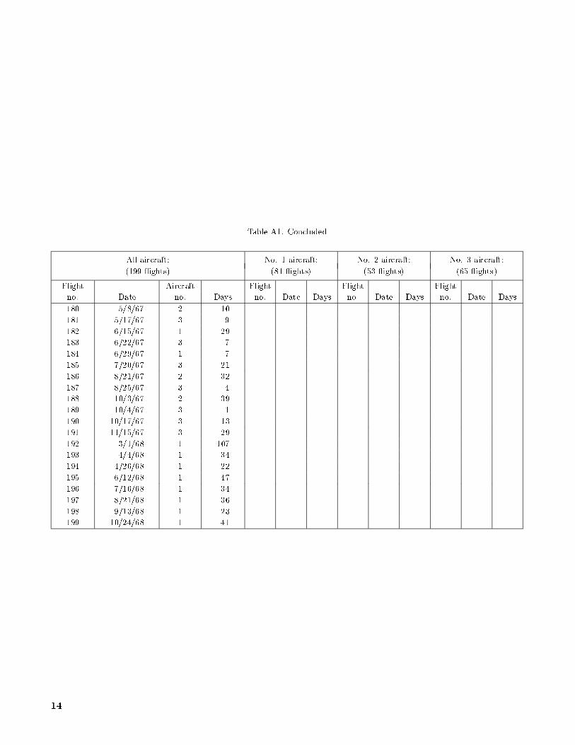
Table A1. Concluded
All aircraft: No. 1 aircraft: No. 2 aircraft: No. 3 aircraft:
(199 ights) (81 ights) (53 ights) (65 ights)
Flight Aircraft Flight Flight Flight
no. Date no. Days no. Date Days no. Date Days no. Date Days
180 5/8/67 2 10
181 5/17/67 3 9
182 6/15/67 1 29
183 6/22/67 3 7
184 6/29/67 1 7
185 7/20/67 3 21
186 8/21/67 2 32
187 8/25/67 3 4
188 10/3/67 2 39
189 10/4/67 3 1
190 10/17/67 3 13
191 11/15/67 3 29
192 3/1/68 1 107
193 4/4/68 1 34
194 4/26/68 1 22
195 6/12/68 1 47
196 7/16/68 1 34
197 8/21/68 1 36
198 9/13/68 1 23
199 10/24/68 1 41
14

References
Ehrlich, Carl F., Jr.; et al. 1991: Personnel Launch Sys-
tem (PLS) Study|Final Report (DRD 12). NASA
CR-187620.
Hallion, Richard P. 1984: On the Frontier|Flight Research
at Dryden, 1946{1981. NASA SP-4303.
Hoey, RobertG.; andDay,RichardE. 1962:MissionPlanning
and Operational Procedures for the X-15 Airplane. NASA
TND-1159.
Love, James E.; and Palmer, John A. 1961: Operational Re-
liability Experience With the X-15 Aircraft. Research-
Airplane-Committee Report on Conference on the
Progress of the X-15 Project|A Compilation of Pa-
pers Presented, U.S. Air Force, U.S. Navy, and NASA,
pp. 277{287.
Love, James E.; and Young, William R. 1965: Component
Performance and Flight Operations of the X-15 Research
Airplane Program. NASATMX-74527.
Love, James E.; and Young, William R. 1966: Survey of
Operation and Cost Experience of the X-15 Airplane as
a Reusable Space Vehicle. NASATND-3732.
Love, James E.; and Young, William R. 1967: Operational
Experience of the X-15 Airplane as a Reusuable Vehicle
System. Space Technology Conference, Soc. Automotive
Engineers, Inc., pp. 198{204. (Available as SAE Paper
670394.)
Miller, Jay 1983: The X-Planes|X-1 to X-29. Specialty
Press.
Piland, William M.; Talay, Theodore A.; and Stone,
Howard W. 1990: Personnel Launch System De�nition.
IAF-90-160.
Row, Perry V.; and Fischel, Jack 1963: Operational Flight-
Test Experience With the X-15 Airplane. AIAA Paper
No. 63-075.
15
REPORT DOCUMENTATION PAGEForm Approved
OMB No. 0704-0188
Public reporting burden for this collection of information is estimated to average 1 hour per response, including the time for reviewing instructions, searching existing data sources,gathering and maintaining the data needed, and completing and reviewing the collection of information. Send comments regarding this burden estimate or any other aspect of thiscollection of information, including suggestions for reducing this burden, to Washington Headquarters Services, Directorate for Information Operations and Reports, 1215 Je�ersonDavis Highway, Suite 1204, Arlington, VA 22202-4302, and to the O�ce of Management and Budget, Paperwork Reduction Project (0704-0188), Washington, DC 20503.
1. AGENCY USE ONLY(Leave blank) 2. REPORT DATE 3. REPORT TYPE AND DATES COVERED
June 1993 Technical Memorandum
4. TITLE AND SUBTITLE
X-15/HL-20 Operations Support Comparison
6. AUTHOR(S)
W. Douglas Morris
7. PERFORMING ORGANIZATION NAME(S) AND ADDRESS(ES)
NASA Langley Research CenterHampton, VA 23681-0001
9. SPONSORING/MONITORING AGENCY NAME(S) AND ADDRESS(ES)
National Aeronautics and Space AdministrationWashington, DC 20546-0001
5. FUNDING NUMBERS
WU 906-11-01-01
8. PERFORMING ORGANIZATION
REPORT NUMBER
L-17190
10. SPONSORING/MONITORING
AGENCY REPORT NUMBER
NASA TM-4453
11. SUPPLEMENTARY NOTES
12a. DISTRIBUTION/AVAILABILITY STATEMENT 12b. DISTRIBUTION CODE
Unclassi�ed{Unlimited
Subject Category 15
13. ABSTRACT (Maximum 200 words)
During the 1960's, the United States X-15 rocket-plane research program successfully demonstrated theability to support a reusable vehicle operating in a near-space environment. The similarity of the proposedHL-20 lifting body concept in general size, weight, and subsystem composition to that of the X-15 provided anopportunity for a comparison of the predicted support manpower and turnaround times with those experiencedin the X-15 program. Information was drawn from both reports and discussions with X-15 program personnelto develop comparative operations and support data. Based on the assumption of comparability between thetwo systems, the predicted sta�ng levels, skill mix, and refurbishment times of an operational HL-20 appear tobe similar to those experienced by the X-15 for ground support. However, safety, environmental, and supportrequirements have changed such that the HL-20 will face a di�erent operating environment than existed atEdwards during the 1950's and 1960's. Today's operational standards may impose additional requirements onthe HL-20 that will add to the maintenance and support burden estimate based on the X-15 analogy.
14. SUBJECT TERMS 15. NUMBER OF PAGES
X-15; HL-20; Operations; Support 16
16. PRICE CODE
A0317. SECURITY CLASSIFICATION 18. SECURITY CLASSIFICATION 19. SECURITY CLASSIFICATION 20. LIMITATION
OF REPORT OF THIS PAGE OF ABSTRACT OF ABSTRACT
Unclassi�ed Unclassi�ed
NSN 7540-01-280-5500 Standard Form 298(Rev. 2-89)Prescribed by ANSI Std. Z39-18298-102