Embed Size (px)
Citation preview

Australia Pacific LNG Project Volume 4: LNG Facility Chapter 11: Water Resources
Volume 4: LNG Facility Chapter 11: Water Resources
March 2010 Page ii Australia Pacific LNG Project EIS
Contents
11. Water resources................................................................................................................. 4
11.1 Introduction.................................................................................................................... 4
11.1.1 Purpose ................................................................................................................. 4
11.1.2 Scope of work........................................................................................................ 5
11.1.3 Legislative framework............................................................................................ 5
11.2 Methodology .................................................................................................................. 7
11.2.1 Groundwater.......................................................................................................... 7
11.2.2 Surface water ........................................................................................................ 7
11.3 Existing environment ..................................................................................................... 8
11.3.1 Environmental values............................................................................................ 8
11.3.2 Water quality objectives ........................................................................................ 9
11.3.3 Groundwater.......................................................................................................... 9
11.3.4 Surface water ...................................................................................................... 10
11.4 Potential impacts ......................................................................................................... 15
11.4.1 Impact assessment ............................................................................................. 15
11.5 Mitigation and management ........................................................................................ 21
11.5.1 Groundwater........................................................................................................ 21
11.5.2 Stormwater system design.................................................................................. 21
11.5.3 Stormwater management plan ............................................................................ 24
11.5.4 Monitoring............................................................................................................ 25
11.6 Conclusions ................................................................................................................. 26
11.6.1 Assessment outcomes ........................................................................................ 26
11.6.2 Commitments ...................................................................................................... 30
References ................................................................................................................................. 31
Figures
Figure 11.1 Extent of inundation 100 years ARI design event - existing ............................................. 13
Figure 11.2 Extent of tidal inundation, including indicative relamation areas ...................................... 14
Figure 11.3 Indicative conceptual drainage strategy............................................................................ 16

Volume 4: LNG Facility Chapter 11: Water Resources
March 2010 Page iii Australia Pacific LNG Project EIS
Tables
Table 11.1 Relevant policy and legislation............................................................................................. 6
Table 11.2 EPP Water environmental values......................................................................................... 8
Table 11.3 LNG facility specific water quality objectives for stormwater management .......................... 9
Table 11.4 Existing boreholes .............................................................................................................. 10
Table 11.5 Climate data ....................................................................................................................... 10
Table 11.6 Gladstone tidal plane data.................................................................................................. 14
Table 11.7 Stormwater drainage design criteria.................................................................................... 16
Table 11.8 Estimated total water demand for construction .................................................................. 19
Table 11.9 Projected water demand (m3/hr) ........................................................................................ 20
Table 11.10 Indicative sewage treatment plant effluent quality ........................................................... 21
Table 11.11 MUSIC model parameters................................................................................................ 23
Table 11.12 Predicted stormwater quality ............................................................................................ 23
Table 11.13 Stormwater maintenance schedule.................................................................................. 24
Table 11.14 Monitoring program .......................................................................................................... 25
Table 11.15 Summary of environmental values, sustainability principles, potential impacts and mitigation measures .............................................................................................................................. 27

Volume 4: LNG Facility Chapter 11: Water Resources
March 2010 Page 4 Australia Pacific LNG Project EIS
11. Water resources
11.1 Introduction
11.1.1 Purpose
This chapter outlines the assessment of groundwater and surface water resources on the liquefied natural gas (LNG) facility site, the potential impacts on those resources and the mitigation of those impacts.
The investigation of surface waters issues for the LNG facility to be constructed near Laird Point, on Curtis Island, Queensland has been presented in the flooding, drainage and stormwater management technical report (Volume 5 Attachment 26). The investigations undertaken to assess the water quantity and quality impacts of the LNG facility included the following:
• Assessment of catchment hydrology, storm runoff flows and flood extents for existing conditions
• Assessment of waterways and water bodies within the LNG facility site
• Potential impacts of development
• Mitigation measures and stormwater flow and quality management for the construction and operational phases of the LNG facility
• Water demand and source water for the LNG facility
• Water quality management and monitoring requirements.
The investigations addressed Section 3.4.1 of the terms of reference (TOR) for the Project’s environmental impact statement that relates to surface water and watercourses such as the following:
• Existing drainage patterns and flow regimes
• Flooding
• Water quality
• Surface water management
• Stormwater management.
The assessment of groundwater issues included in Section 3.4.2 of the TOR included:
• Review of existing groundwater levels and quality
• Identification of potential impacts
• Identification of appropriate management and mitigation strategies.
Of its 12 sustainability principles, Australia Pacific LNG is guided by a subset of relevant sustainability principles when identifying potential impacts the Project may have on water resources for the Gladstone Region. The Australia Pacific LNG sustainability principles that relate to water resources are:
• Minimising adverse environmental impacts and enhancing environmental benefits associated with Australia Pacific LNG’s activities, products or services; conserving, protecting, and

Volume 4: LNG Facility Chapter 11: Water Resources
March 2010 Page 5 Australia Pacific LNG Project EIS
enhancing where the opportunity exists, the biodiversity values and water resources in its operational areas
• Using resources efficiently, reducing the intensity of materials used and implementing programs for the reduction and reuse of waste
• Identifying, assessing, managing, monitoring and reviewing risks to Australia Pacific LNG’s workforce, its property, the environment and the communities affected by its activities.
Under these principles, surface water resources are reflected in a number of ways. Surface water is a key resource for the people and ecology of Australia. The LNG facility through a number of strategies, will endeavour to utilise water efficiently and be as self sufficient as practical for all construction and operational water requirements. Australia Pacific LNG’s sustainability principles will be applied to the planning, design, construction and operation of the LNG facility. This will ensure impacts on surface water flows and water quality do not aversely impact people or the environment.
11.1.2 Scope of work
The scope of work undertaken in the assessment of potential water resources impacts for the LNG facility included the following generic activities, where appropriate:
• Description of existing conditions
• Description of environmental values
• Identification of potential impacts
• Mitigation measures
• Risk assessment.
In detail, the following scope of work was undertaken in order to assess potential impacts of the LNG facility on surface water flows and water quality:
• Estimation of peak flows for design storm events
• Definition of existing flood-prone land and land subject to tidal inundation
• Review of existing water quality of surface waterways
• Assessment of reliable yield available from harvesting of stormwater runoff
• Assessment of potential impacts on surface water flows and water quality
• Preparation of a site-based stormwater management plan to minimise potential impacts during the construction and operation phases, including monitoring of stormwater discharge quality.
11.1.3 Legislative framework
Certain legislation needs to be considered when assessing the potential impacts of the LNG facility construction and operation activities on groundwater and surface waters in the study area, which principally includes:
• Water Act 2000 and water resource and resource operations plans, where applicable
• Environmental Protection Act 1994 (EP Act)
• Environmental Protection Regulation 2008

Volume 4: LNG Facility Chapter 11: Water Resources
March 2010 Page 6 Australia Pacific LNG Project EIS
• Environmental Protection (Water) Policy 2009 (EPP Water)
• Sustainable Planning Act 2009
• Petroleum and Gas (Production and Safety) Act 2004 (PAG Act).
An overview of the relevant Queensland legislation referred to above and its purpose is provided in Volume 4 Chapter 2. Those statutory plans, environmental protection policies, legislation and regulations directly relevant to activities impacting on water resources undertaken by the Project are discussed in Table 11.1.
Table 11.1 Relevant policy and legislation
Policy or legislation Description Relevance
Water Act 2000 The Water Act 2000 provides for the sustainable management of water and other resources. The Act regulates the use and allocation of water through water authorisations and water resource plans
Under this Act, a water licence is required for all operations that are not directly related to activities authorised under the PAG Act that will interfere with surface water or watercourses
The Act requires that permits be obtained for the removal of riverine vegetation and for the excavation or placing of fill in a watercourse (riverine protection permit)
A riverine protection permit will not be required if carried out under a licence, petroleum lease or authority to prospect under the PAG Act
Water Act 2000 - State water resource and resource operations plans
Under the Water Act 2000, water resource plans (WRPs) have been developed to define the availability and allocation of water and to ensure the sustainable management of water in Queensland. The objectives of the WRPs are to balance the needs of humans and the environment in a sustainable manner
Curtis Island is not within a WRP area
EP Act The object of the EP Act is to protect Queensland’s environment while allowing for development that improves the total quality of life, both now and in the future, in a way that maintains the ecological processes on which life depends
Under Section 319 of the EP Act, all persons must not carry out any activity that causes, or is likely to cause, environmental harm unless the person takes all reasonable and practicable measures to prevent or minimize the harm. This general environmental duty requires the implementation of pro-active

Volume 4: LNG Facility Chapter 11: Water Resources
March 2010 Page 7 Australia Pacific LNG Project EIS
Policy or legislation Description Relevance measures to prevent environmental degradation
EPP Water The purpose of the EPP Water is to achieve the object of the EP Act in relation to Queensland waters
Section 6 of the EPP Water describes the environmental values to be enhanced or protected. The relevant environmental values vary depending on the ecological value of the water, level of disturbance and intended use of the water
Sustainable Planning Act 2009 The Sustainable Planning Act 2009 provides the framework for Queensland’s planning and development assessment system
The Act requires that a development permit is obtained for operational work that involves the removal, destruction or damage of a marine plant (with limited exceptions) or operational work that involves the constructing or raising of waterway barrier works
PAG Act The purpose of this Act is to facilitate and regulate the carrying out of responsible petroleum activities and the development of a safe, efficient and viable petroleum and fuel gas industry
The distillation, production, processing, refining, storage and transport of fuel gas are included in petroleum activities covered by the Act
The make good obligation stipulated in the PAG Act (Part 9 Sections 244 to 280) indicates that if the petroleum activity unduly affects an existing water bore, the tenure holder must implement restorative measures to ensure a suitable supply of water to the owner of the bore, or compensate the owner for being unduly affected
11.2 Methodology
11.2.1 Groundwater
The assessment of potential impacts of the LNG facility on groundwater consisted of:
• Reviewing existing groundwater resources on the site
• Identifying potential impacts on groundwater levels, flows and quality, and on groundwater dependent ecosystems
• Devising monitoring, management and mitigation actions necessary to address the identified impacts.
11.2.2 Surface water
The assessment of potential impacts on surface waterways comprised the following:
• Review of regional climate data in the absence of site-specific data for Curtis Island

Volume 4: LNG Facility Chapter 11: Water Resources
March 2010 Page 8 Australia Pacific LNG Project EIS
• Review of drainage characteristics for the site
• Review of water quality in surface watercourses
• Estimation of 100 years ARI peak flows and extent of inundation for surface watercourses on the site
• Identification of extent of tidal inundation on the site
• Assessment of conceptual drainage strategy for the LNG facility
• Estimation of stormwater runoff water quality
• Estimation of stormwater as water supply source for the LNG facility
• Assessment of proposed treated sewage effluent disposal strategy
• Identification and assessment of appropriate management and mitigation strategies relating to the potential impacts.
The assessment of potential impacts on the waters in Port Curtis is addressed in Volume 4 Chapter 10.
11.3 Existing environment
11.3.1 Environmental values
Environmental values (EVs) are the qualities of waterways that need to be protected from the effects of pollution, waste discharges and deposits to ensure healthy aquatic ecosystems and waterways that are safe and suitable for community use. These range from the maintenance and protection of healthy aquatic ecosystems, health and safety, commercial and cultural heritage values.
The EPP Water was established to achieve the objectives of the EP Act in relation to Queensland waters and provides the framework for establishing EVs and water quality objectives (WQOs) for Queensland waters. The EVs scheduled under the EPP Water and the respective EVs applicable to Port Curtis are listed in Table 11.2.
Table 11.2 EPP Water environmental values
EPP Water EVs Port Curtis EVs
Aquatic ecosystems Local – aquatic ecosystems within Port Curtis
Regional – Great Barrier Reef Marine Park
Aquaculture use Commercial fishing
Primary recreation Swimming, water sports and recreational fishing
Secondary recreation Wading, boating
Drinking water NA
Industrial purposes LNG facility site water usage, cooling water for other industries, export of resources from Central Queensland.
Cultural and spiritual values Cultural significance of Port Curtis and Graham Creek, Indigenous Traditional Owners (Gurang, Gooreng Gooreng and Bailai)

Volume 4: LNG Facility Chapter 11: Water Resources
March 2010 Page 9 Australia Pacific LNG Project EIS
Furthermore, no additional EVs have been established for the Port Curtis area within the Queensland Water Quality Guidelines 2009 (Department of Environment and Resource Management (DERM) 2009).
11.3.2 Water quality objectives
The WQOs for discharges to surface watercourses, tidal estuaries and marine waters are set out in the Queensland Water Quality Guidelines (DERM 2009). Where site-specific targets do not exist the Australia and New Zealand Environment and Conservation Council/Agriculture and Resource Management Council of Australia and New Zealand (ANZECC/ARMCANZ) (2000) are used as a default set of targets. Specific WQOs have been set in consideration of ANZECC/ARMCANZ (2000), background conditions in Port Curtis and operational and design experience. The WQOs for discharges to the marine waters in Port Curtis are discussed in Volume 4 Chapter 10.
Both the ANZECC/ARMCANZ Guidelines and Queensland Water Quality Guidelines were established mainly for flowing waters within streams, estuaries and marine waters, or standing water bodies within wetlands and lakes.
The EPP Water was established under the EP Act to achieve WQOs and EVs for Queensland waters. For the Port Curtis area, the WQOs are listed in Table 11.3. The listed parameters are water quality parameters for receiving waterways.
Table 11.3 LNG facility specific water quality objectives for stormwater management
Indicator Water quality objectives
pH 7.0 – 8.5
Dissolved oxygen (% saturation) 80
Turbidity (NTU) 20
Total suspend solids (mg/L) 30
The Healthy Waterways Water Sensitive Urban Design Technical Guidelines (Healthy Waterways 2006) notes that many regions around Australia are adopting load-based objectives instead of concentration-based objectives because of the ongoing issues that many areas have found with using concentration-based receiving water targets as discharge criteria. The objectives adopted by Healthy Waterways for southeast Queensland are:
• 80% reduction in total suspended solids load
• 60% reduction in total phosphorus load
• 45% reduction on total nitrogen load, and
• 90% reduction in gross pollutant load.
11.3.3 Groundwater
Information on the existing groundwater resources in the vicinity of the LNG facility was obtained from a search of previous studies undertaken and a review of the Queensland groundwater database.
There are two registered sub-artesian groundwater bores located on Curtis Island in the vicinity of the LNG facility. The bores are registered for water supply. BH 91326 is located within the LNG plant site and BH 91325 is located approximately 3km to the southeast of the site. The quality of groundwater is

Volume 4: LNG Facility Chapter 11: Water Resources
March 2010 Page 10 Australia Pacific LNG Project EIS
described as brackish or salty. Relevant information relating to the two bores is summarised in Table 11.4 .
Table 11.4 Existing boreholes
Parameter BH 91325 BH 91326
Conductivity (μS/cm) 12,000 Salty (no measurement recorded)
Yield (L/s) 3.0 0.5
Depth to water (m) 10.6 10.6
Depth to aquifer 22.7 – 27.3 21.2 – 30.3
11.3.4 Surface water
Rainfall and evaporation
The nearest long-term rainfall gauges to the site are located in Gladstone, where the long-term mean annual rainfall is approximately 950mm. The records of monthly average rainfall, evaporation and temperature data at Gladstone for the period 1957 to 2009 have been obtained from the Bureau of Meteorology climate averages database for the Radar Hill station. This is discussed in Volume 4 Chapter 4. The monthly data are summarised in Table 11.5.
The climatic data exhibits high seasonality with the highest rainfall and runoff occurring between December and March. The higher evaporation begins in October and extends through to March, reflecting the higher temperatures during those months.
Table 11.5 Climate data
Month Jan Feb Mar Apr May Jun Jul Aug Sep Oct Nov Dec Total year
Rainfall (mm)
143.4 143.4 82.6 46.4 59.6 38.9 34.4 31.2 26.2 61.3 73.2 128.8 869.7
Days rain ≥10mm
4 4 2 1 1 1 1 1 1 2 2 3 23
Potential Evaporation (mm)
195 165 164 132 105 90 96 109 132 170 183 195 1736
Temperature (°C)
22.5-31.2
22.4-30.9
21.5-30.2
19.6-28.4
17.0-25.7
14.3-23.2
13.4-22.8
14.3-24.1
16.4-26.5
18.7-28.4
20.5-29.9
21.9-31.0
18.5-27.7
The average annual rainfall recorded at the Radar Hill station is approximately 10% less than the long-term average annual rainfall obtained for the period 1872 to 2009 using the composite records for the Post Office and Radar Hill gauges.
Drainage
The LNG facility site is located on the western side of Curtis Island approximately 1.5km south of Laird Point and Graham Creek. It is traversed by a drainage lines comprising three ephemeral tributaries discharging from the site into Port Curtis approximately 1.3km south of Laird Point. The local

Volume 4: LNG Facility Chapter 11: Water Resources
March 2010 Page 11 Australia Pacific LNG Project EIS
catchment covers the LNG facility site and extends to the southeast, covering a total area of over 284ha. The central and upper reaches of the catchment comprise of timbered hills and valleys. The lower catchment comprises approximately 50ha of tidal flats and mangroves at the entrance of the drainage line as it meets Port Curtis.
The drainage lines are ephemeral. It is not proposed to utilise surface water as a primary source of supply. This is due to a number of factors, including the extreme seasonality of rainfall and resultant runoff, the large storage required, and the low yield and reliability of supply. There are no stream flow records for the drainage lines within the site or for any watercourses on Curtis Island.
Soils
The soils on the site and in the catchment are gravelly sandy loams on the hillsides, having dispersive nature and a medium runoff potential. Initial site investigations indicated the presence of actual acid sulphate soils (ASS) and potential acid sulphate soils. The assessment of the soils on the site is presented in Volume 4 Chapter 5.
Water quality
No information is available from DERM databases with regard to water quality and condition of the natural drainage lines for the LNG facility site. Reconnaissance surveys of the site were carried out in order to obtain some qualitative assessment of the condition of the natural drainage on site. During these surveys, a natural melaleuca wetland and a small farm dam were located on the site. Both sites were quite degraded with limited EVs. The dam was supplied by groundwater from a nearby bore, which is no longer used.
During a later site visit undertaken to assess ASS conditions on the site, a melaleuca wetland was located approximately 200m to the northeast of the dam located previously. Both the dam and wetland were quite degraded and are considered to have limited EVs, due to the lack of diversity and habitat present, as well as the damage made by cattle and horses. Volume 4 Chapter 9 details the habitat status of the wetland and farm dam.
Volume 5 Attachment 26 details the water sampling results from the farm dam, however in summary there were naturally elevated chloride, sodium and copper readings from the groundwater, as well as organic nitrogen from the presence of an algae bloom. Generally all other parameters were low.
Although one water sample was taken from the farm dam, it was not considered reflective of surface water as it had originated from a nearby groundwater bore some time previously. Similarly, it is not considered to be a true reflection of the groundwater conditions due to the unknown time elapsed since the water had been drawn from the bore.
The site has previously been used for cattle grazing and runoff quality is expected to be similar to that for low intensity grazing. Toxic contamination of runoff is considered unlikely as no disused cattle dip or other potential sources of contamination was found on the site. The site is no longer used for cattle grazing, but wild horses were sited during field inspections.
Flooding
Storm runoff hydrographs were calculated at the catchment outlet and a number of locations within the LNG facility site using the RAFTS hydrologic model. RAFTS is a non-linear runoff routing model that calculates runoff hydrographs from excess rainfall for rural and urban catchments ranging in area from less than 1ha to over 1,000km2.

Volume 4: LNG Facility Chapter 11: Water Resources
March 2010 Page 12 Australia Pacific LNG Project EIS
The principal purpose of the RAFTS modelling was to determine peak flows at selected locations along the natural drainage network for input to the hydraulic model. This was done to estimate the extent of inundation in the 100 years average recurrence interval (ARI) design event.
Design rainfall intensity-frequency-duration data was determined for the Curtis Island locality in accordance with Australian Rainfall and Runoff (AR&R 2001).
The approximate extent of inundation of the LNG facility site in the 100 years ARI design event was determined using a HEC-RAS hydraulic model with peak flows obtained from the RAFTS hydrologic model.
HEC-RAS is a one-dimensional hydraulic model that was developed at the Hydrologic Engineering Center by the United States Army Corps of Engineers. The model is designed to perform one-dimensional hydraulic calculations for natural and constructed channel networks. The model can simulate branched networks and hydraulic structures including weirs, bridges and culverts.
The HEC-RAS model of the study area included the main drainage line and two tributary branches, with peak flows input for seven reaches. The cross sections for the model were extracted from the contour survey information for the site.
The HEC-RAS modelling results indicate that floodwaters are generally confined to 60-180m width along the main drainage line and the tributary branches across the site and spreads out over the broad tidal flats that extend to the entrance to marine waters. The extent of inundation of the site in the 100 years ARI design event for existing conditions is presented in Figure 11.1.

Volume 4: LNG Facility Chapter 11: Water Resources
March 2010 Page 13 Australia Pacific LNG Project EIS
Figure 11.1 Extent of inundation 100 years ARI design event - existing
Tidal inundation
Natural ground levels on the site vary between approximately RL1.5m Australian height datum (AHD) on the tidal flats adjacent to the mangroves at the mouth of the drainage line up to RL 40m AHD on the hilltops.
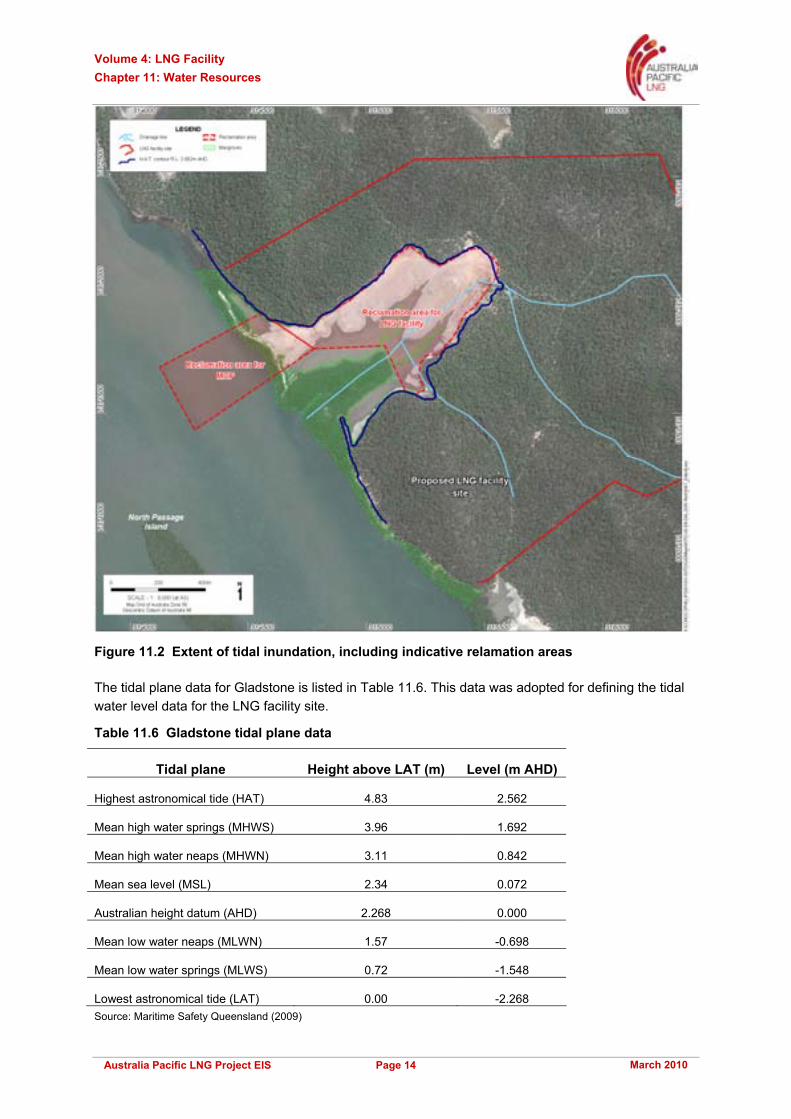
The tidal flats are prone to occasional tidal inundation on higher spring tides. The maximum level for tidal inundation corresponds to highest astronomical tide (HAT) level (RL 2.562m AHD), resulting in a maximum depth of tidal inundation of approximately 1.0m. The extent of tidal inundation of the site is presented in Figure 11.2.
Volume 4: LNG Facility Chapter 11: Water Resources
March 2010 Page 14 Australia Pacific LNG Project EIS
Figure 11.2 Extent of tidal inundation, including indicative relamation areas
The tidal plane data for Gladstone is listed in Table 11.6. This data was adopted for defining the tidal water level data for the LNG facility site.
Table 11.6 Gladstone tidal plane data
Tidal plane Height above LAT (m) Level (m AHD)
Highest astronomical tide (HAT) 4.83 2.562
Mean high water springs (MHWS) 3.96 1.692
Mean high water neaps (MHWN) 3.11 0.842
Mean sea level (MSL) 2.34 0.072
Australian height datum (AHD) 2.268 0.000
Mean low water neaps (MLWN) 1.57 -0.698
Mean low water springs (MLWS) 0.72 -1.548
Lowest astronomical tide (LAT) 0.00 -2.268 Source: Maritime Safety Queensland (2009)

Volume 4: LNG Facility Chapter 11: Water Resources
March 2010 Page 15 Australia Pacific LNG Project EIS
Tidal inundation of the tidal flats may also occur during storm surges that enter Port Curtis. Storm tide statistics for Gladstone suggest that the 100 years ARI storm surge level may be 0.8m above the HAT level (Harper 1998) with the 1,000 years ARI storm surge level approximately 1.7m above HAT level. Thus, land below approximately RL 4.3m AHD may be inundated in extreme ocean storm surge events. Volume 4 Chapter 10 provides an estimated 1,000 years ARI storm surge level of 4.41m AHD, with allowance for projected climate change effects.
11.4 Potential impacts
The LNG facility development will include the following bulk earthworks that will impact on surface water drainage on the site and adjoining land:
• Filling of the tidal flats and fringing areas to RL 6.0m AHD
• Extensive cut and fill earthworks to create building platforms
• Diversion of main drainage lines to convey runoff from uphill areas around the site.
In addition to the changed drainage lines and outlet locations, the construction of the LNG facility will create significant impervious areas due to buildings, roadways and storage tanks.
Thus, the development has the potential to impact on the quantity, quality and distribution of runoff discharged from the site.
It is not proposed to utilise the groundwater as a source of supply for the LNG facility during construction or operational phases. Therefore, the LNG facility is not expected to have an impact on groundwater quality or quantity under normal operating circumstances.
Accidental spills or leakage of fuels or chemicals stored on the site may seep to the groundwater. Surface drainage infrastructure will be provided to contain accidental spills or leaks of fuels or chemicals directing them to collection and treatment and appropriate disposal, as discussed below.
11.4.1 Impact assessment
Catchment drainage
Construction of the LNG facility will include extensive filling of the tidal flats area and major cut and fill earthworks over the balance of the site to provide building platforms, resulting in diversion of runoff from upstream areas external to the site around the site. The bulk earthworks will include construction of the diversion channels, formation of the internal drainage swales and construction of the sediment ponds.
All runoff from the construction works area will be directed to the sediment ponds for treatment prior to discharge to Port Curtis. The sediment ponds will capture the first 25mm of runoff. Riprap aprons will be constructed at all discharge outlets to prevent scour and erosion.
Runoff from the upper catchment areas beyond the LNG facility site will be diverted via a channel. This will be constructed around the southern perimeter of the site and runoff from the hills on the northern side of the site is to be diverted via a drainage channel to be constructed along the northern boundary of the site. The conceptual drainage strategy for the LNG facility is illustrated on Figure 11.3. It is recognised that the drainage strategy may be amended during the detailed design phase.
The stormwater drainage system design criteria are summarised in Table 11.7.

Volume 4: LNG Facility Chapter 11: Water Resources
March 2010 Page 16 Australia Pacific LNG Project EIS
Figure 11.3 Indicative conceptual drainage strategy

Volume 4: LNG Facility Chapter 11: Water Resources
March 2010 Page 17 Australia Pacific LNG Project EIS
Table 11.7 Stormwater drainage design criteria
Plant area/facility Average recurrence intervals (yrs)
Inside plant limits 25
Outside plant limits 10
Administration areas 5
Access roads 5
Secondary roads 10
Primary roads 25
Construction areas 2
Materials storage 2
Permanent storage 5
The northern bypass drain will convey runoff from the hillsides and batter slope adjoining the plant site. The preliminary design for the northern bypass drain comprises a trapezoidal cross section having a 5m wide invert, 1:3 side slopes, minimum depth of 1.5m, and a minimum longitudinal slope of 0.4%.
The preliminary conceptual designs for the stormwater system will be finalised during the detailed design phase.
All runoff from the LNG facility will be collected and conveyed in shallow swale drains to sediment basins and discharged from the site if not reused. Runoff from the LNG train and storage tank areas and from the southern sector of the plant is to be directed to the hydrotest pond prior to discharge to Port Curtis at the entrance to the existing drainage line. Runoff from the administration and maintenance facilities area and the temporary accommodation facility (TAF) area at the eastern end of the site is to be directed to a smaller sediment basin prior to discharge to the bypass channel. The sediment basins will provide minor reductions in peak flows discharged from the LNG facility.
Storm runoff flows for post-development conditions were calculated using the RAFTS hydrologic model for the 100 years ARI design storm events in order to determine the outlet capacities for the two sediment ponds and design flows for the bypass channel.
An initial loss of 25mm and continuing loss of 2.5mm/hr were adopted for the pervious areas as for the existing conditions modelling undertaken previously, with an initial loss of 1mm and zero continuing loss for the impervious areas.
The modelling predicted that the peak total flow discharged from the plant site and upper catchment would increase by approximately 25% from 47.4m3/s to 59.0m3/s.
The predicted increases in peak total flow discharged from the LNG facility site and upper catchment are due to the improved hydraulic characteristics of the drainage system. This is coupled with the improved hydraulic characteristics of the bypass channels relative to the existing natural drainage lines. The critical storm duration was found to be shortened from 120 minutes to 90 minutes due to the improved drainage.

Volume 4: LNG Facility Chapter 11: Water Resources
March 2010 Page 18 Australia Pacific LNG Project EIS
Stormwater quality
There will be high erosion potential during the construction period during rain events due to the removal of vegetation and associated earthworks. There is also the potential release of contaminants that may be attached to the soils that enter drainage lines and subsequently flow into Port Curtis.
The creation of impervious areas for buildings, LNG storage tanks, internal roadways and ancillary paved areas will increase the volumes of storm runoff from the site relative to the existing conditions.
The primary pollutants of concern in runoff discharged from the LNG facility are suspended solids and fuels/chemicals that may be used at the LNG facility. Stormwater that may be contaminated by process chemicals or other materials from process areas will be collected in a separate drainage system and directed to a dedicated treatment facility.
Stormwater runoff from plant process areas will be routed to a treatment process comprising a coalescing plate interceptor separator followed by dissolved air flotation and tertiary filtration prior to disposal by irrigation with the sewage effluent irrigation. This strategy will prevent fuels and chemicals being discharged to Port Curtis in stormwater runoff. Excess treated stormwater and treated sewage wastewater will be discharged to Port Curtis.
Water management
Freshwater source
The investigation to determine the appropriate water source and treatment requirements for the LNG plant (Bechtel 2009a) concluded that stormwater runoff was not a feasible primary source of total water demand due to the:
• Extreme seasonal variability of rainfall
• Large storage facilities being required to capture adequate runoff
• High probability that the reliable yield of the system would not be sufficient to satisfy the demands of LNG plant.
Therefore, it is proposed that a seawater desalination plant (most likely using reverse osmosis technology) will be used to obtain the bulk of the water required for processing and utility purposes. Stormwater runoff collected in the hydrotest pond may be used as a supplementary supply source for the potable water unit or desalination plant if the water quality is suitable for reuse.
The yield analysis for the stormwater system and hydrotest pond confirmed the findings of the investigation to determine the appropriate water source and treatment requirements for the LNG plant that stormwater runoff could not feasibly meet all water demand for the LNG facility.
Construction
A desalination plant will be installed during the construction period to provide water for construction use. Packaged potable water for drinking will be transported to the site until the desalination plant becomes operational.
Table 11.8 sets out the estimated potable and service water requirements during the construction period.
Volume 4: LNG Facility Chapter 11: Water Resources
March 2010 Page 19 Australia Pacific LNG Project EIS
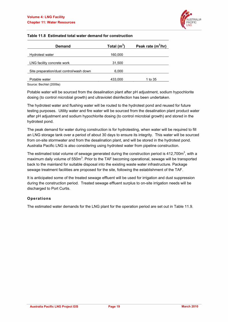
Table 11.8 Estimated total water demand for construction
Demand Total (m3) Peak rate (m3/hr)
Hydrotest water 160,000
LNG facility concrete work 31,500
Site preparation/dust control/wash down 6,000
Potable water 433,000 1 to 35 Source: Bechtel (2009a)
Potable water will be sourced from the desalination plant after pH adjustment, sodium hypochlorite dosing (to control microbial growth) and ultraviolet disinfection has been undertaken.
The hydrotest water and flushing water will be routed to the hydrotest pond and reused for future testing purposes. Utility water and fire water will be sourced from the desalination plant product water after pH adjustment and sodium hypochlorite dosing (to control microbial growth) and stored in the hydrotest pond.
The peak demand for water during construction is for hydrotesting, when water will be required to fill an LNG storage tank over a period of about 30 days to ensure its integrity. This water will be sourced from on-site stormwater and from the desalination plant, and will be stored in the hydrotest pond. Australia Pacific LNG is also considering using hydrotest water from pipeline construction.
The estimated total volume of sewage generated during the construction period is 412,700m3, with a maximum daily volume of 550m3. Prior to the TAF becoming operational, sewage will be transported back to the mainland for suitable disposal into the existing waste water infrastructure. Package sewage treatment facilities are proposed for the site, following the establishment of the TAF.
It is anticipated some of the treated sewage effluent will be used for irrigation and dust suppression during the construction period. Treated sewage effluent surplus to on-site irrigation needs will be discharged to Port Curtis.
Operations
The estimated water demands for the LNG plant for the operation period are set out in Table 11.9.
Volume 4: LNG Facility Chapter 11: Water Resources
March 2010 Page 20 Australia Pacific LNG Project EIS
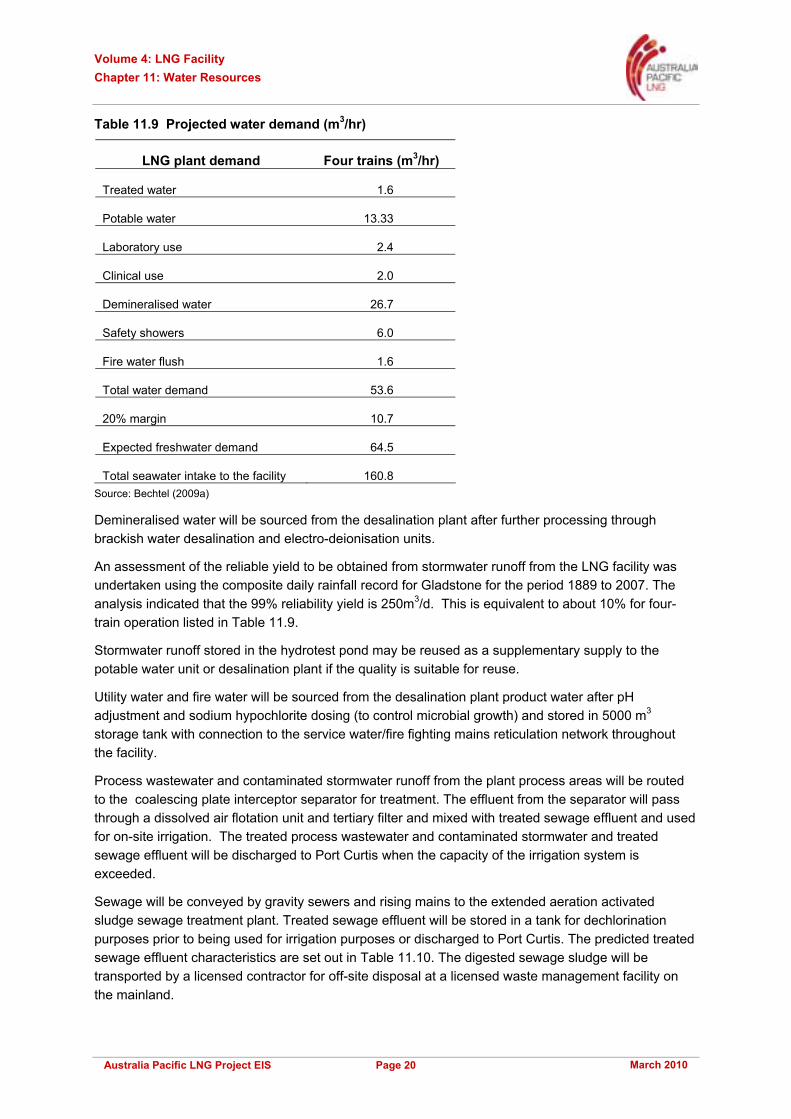
Table 11.9 Projected water demand (m3/hr)
LNG plant demand Four trains (m3/hr)
Treated water 1.6
Potable water 13.33
Laboratory use 2.4
Clinical use 2.0
Demineralised water 26.7
Safety showers 6.0
Fire water flush 1.6
Total water demand 53.6
20% margin 10.7
Expected freshwater demand 64.5
Total seawater intake to the facility 160.8 Source: Bechtel (2009a)
Demineralised water will be sourced from the desalination plant after further processing through brackish water desalination and electro-deionisation units.
An assessment of the reliable yield to be obtained from stormwater runoff from the LNG facility was undertaken using the composite daily rainfall record for Gladstone for the period 1889 to 2007. The analysis indicated that the 99% reliability yield is 250m3/d. This is equivalent to about 10% for four-train operation listed in Table 11.9.
Stormwater runoff stored in the hydrotest pond may be reused as a supplementary supply to the potable water unit or desalination plant if the quality is suitable for reuse.
Utility water and fire water will be sourced from the desalination plant product water after pH adjustment and sodium hypochlorite dosing (to control microbial growth) and stored in 5000 m3 storage tank with connection to the service water/fire fighting mains reticulation network throughout the facility.
Process wastewater and contaminated stormwater runoff from the plant process areas will be routed to the coalescing plate interceptor separator for treatment. The effluent from the separator will pass through a dissolved air flotation unit and tertiary filter and mixed with treated sewage effluent and used for on-site irrigation. The treated process wastewater and contaminated stormwater and treated sewage effluent will be discharged to Port Curtis when the capacity of the irrigation system is exceeded.
Sewage will be conveyed by gravity sewers and rising mains to the extended aeration activated sludge sewage treatment plant. Treated sewage effluent will be stored in a tank for dechlorination purposes prior to being used for irrigation purposes or discharged to Port Curtis. The predicted treated sewage effluent characteristics are set out in Table 11.10. The digested sewage sludge will be transported by a licensed contractor for off-site disposal at a licensed waste management facility on the mainland.

Volume 4: LNG Facility Chapter 11: Water Resources
March 2010 Page 21 Australia Pacific LNG Project EIS
Table 11.10 Indicative sewage treatment plant effluent quality
Parameter Concentration
pH 6.5 - 7.5
BOD5 10 - 20mg/L
Oil 5 - 10mg/L
Total nitrogen < 4mg/L as N
Total Kjeldahl nitrogen 1 - 4mg/L
Ammonia nitrogen 1 - 4mg/L
Total phosphorus < 1mg/L
Chlorine 1 - 2mg/L
Total dissolved solids 250mg/L Source: Bechtel (2009b)
It is estimated the maximum volume of treated effluent during the plant operations period will be approximately 84m3/d (Bechtel 2009b). This is based on an average plant population of 150 persons, including visitors and transient workers, and a maximum population of 250 persons. An irrigation disposal area of up to 28ha would be required, based on effluent quantities and an application rate of 3mm/day, equivalent to the minimum monthly average evaporation rate. A suitable irrigation area could be developed on the northern side of the plant where the saddle between the hills is to be filled and re-profiled. Australia Pacific LNG will continue to assess options.
11.5 Mitigation and management
Through the implementation of appropriate stormwater management measures, Australia Pacific LNG will manage stormwater generated at the LNG facility to minimise changes in the quality of the marine waters adjacent to the site.
11.5.1 Groundwater
Potential impacts to groundwater management for the LNG facility will be managed to ensure that groundwater is protected from contamination and that the ecological health of groundwater is maintained. Spills and stormwater runoff from plant process areas will be separated from surface runoff and treated separately and used to the extent practical for on-site irrigation with treated sewage effluent in order to minimise the potential for contamination of groundwater by pollutants seeping to groundwater.
It is proposed to undertake baseline monitoring of groundwater levels and water quality in order to obtain additional information on groundwater conditions for existing and post-development conditions.
11.5.2 Stormwater system design
It is proposed to construct the sediment basin and hydrotest pond and internal swale drains during the initial bulk earthworks activities. All runoff from the site during the construction period will be directed to the sediment basin and hydrotest pond via the swale drains in order to minimise the sediment load in run-off discharged from the site.

Volume 4: LNG Facility Chapter 11: Water Resources
March 2010 Page 22 Australia Pacific LNG Project EIS
An erosion and sediment control plan will be prepared in accordance with relevant guidelines (Institution of Engineers Australia 1996) for the construction period. The plan will include additional temporary sediment control devices including the installation of silt fences, vegetated buffer strips and diversion bunds, as appropriate.
Due to the LNG facility being located immediately adjacent to Port Curtis, it is not considered necessary to prevent increases in peak flows discharged from the site during storm events. Outlets will be maintained to ensure that peak discharge quantities can be managed, including locating bypass drains above HAT level at RL 3.0m AHD in order to prevent mangrove intrusion into the lowest sections. The outlets are to include rock energy dissipation works to prevent scour and erosion downstream of the outlets. These will be designed in accordance with Brisbane City Council creek erosion control guidelines or similar. The Council guidelines have been derived from a design developed by McLaughlin Water Engineers Ltd for the Denver, Colorado, Urban Drainage and Flood Control District in 1986, which have been used throughout the world since that date.
The embankments and spillways on the sediment ponds will be designed in accordance with the relevant guidelines and standards. The ponds will have a perforated pipe low level outlet with geotextile and gravel surround and will also have emergency spillways to discharge excess stormwater flows.
The removal of suspended solids and fuels/chemicals is to be the focus of the stormwater treatment system. As stated above, stormwater that may be impacted by process chemicals or materials from process areas will be collected in a separate drainage system and directed to a dedicated treatment facility.
The stormwater treatment system for the operation period comprises vegetated swales, sediment basin and hydrotest pond to reduce suspended solids, nutrients and fuels/chemicals from stormwater runoff.
Stormwater that may be impacted by process chemicals or other materials from process areas will be collected in a separate drainage system and directed to a dedicated treatment facility.
The performance of the stormwater quality management strategy was assessed using the MUSIC (model for urban stormwater improvement conceptualisation) stormwater runoff and quality model. MUSIC was developed by the Co-operative Research Centre for Catchment Hydrology. It simulates the hydrologic and water quality performance of stormwater systems at a range of temporal and spatial scales suitable for catchment areas from 1ha up to 100km2, using time-steps of six minutes up to one day. The modelling is normally undertaken on a continuous simulation basis in order to simulate cumulative pollutant loadings and treatment.
MUSIC comprises a conceptual rainfall runoff model that is coupled with a pollutant model to generate runoff and pollutant loads. The removal of the principal pollutants (suspended solids, nutrients and gross solids) contained in storm runoff through treatment devices is simulated using a range of device dependent conceptual models.
The MUSIC modelling was undertaken using a time-step of six minutes, with rainfall and evaporation data for Rockhampton for the period 1950 to 1959. Rockhampton rainfall and evaporation were adopted for the modelling as Rockhampton is the nearest station in the MUSIC database. The mean annual rainfall for the Rockhampton simulation period is 999mm and is the closest to the long-term average rainfall at Gladstone of 966mm for the period 1872 to 2008.
The estimation of stormwater runoff and quality was undertaken using parameters recommended in Brisbane City Council (BCC) guidelines (BCC 2003) for industrial developments and urban residential
Volume 4: LNG Facility Chapter 11: Water Resources
March 2010 Page 23 Australia Pacific LNG Project EIS
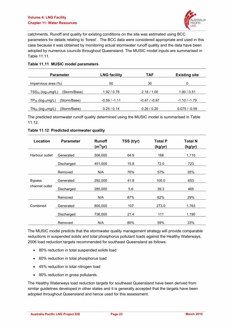
catchments. Runoff and quality for existing conditions on the site was estimated using BCC parameters for details relating to ‘forest’. The BCC data were considered appropriate and used in this case because it was obtained by monitoring actual stormwater runoff quality and the data have been adopted by numerous councils throughout Queensland. The MUSIC model inputs are summarised in Table 11.11.
Table 11.11 MUSIC model parameters
Parameter LNG facility TAF Existing site
Impervious area (%) 50 30 0
TSS50 (log10mg/L) (Storm/Base) 1.92 / 0.78 2.18 / 1.00 1.90 / 0.51
TP50 (log10mg/L) (Storm/Base) -0.59 / -1.11 -0.47 / -0.97 -1.10 / -1.79
TN50 (log10mg/L) (Storm/Base) 0.25 / 0.14 0.26 / 0.20 0.075 / -0.59
The predicted stormwater runoff quality determined using the MUSIC model is summarised in Table 11.12.
Table 11.12 Predicted stormwater quality
Location Parameter Runoff (m3/yr)
TSS (t/yr) Total P (kg/yr)
Total N (kg/yr)
Generated 508,000 64.9 168 1,110
Discharged 451,000 15.8 72.0 723
Harbour outlet
Removed N/A 76% 57% 35%
Generated 292,000 41.8 105.0 653
Discharged 285,000 5.6 39.3 465
Bypass channel outlet
Removed N/A 87% 62% 29%
Generated 800,000 107 273.0 1,763
Discharged 736,000 21.4 111 1,190
Combined
Removed N/A 80% 59% 33%
The MUSIC model predicts that the stormwater quality management strategy will provide comparable reductions in suspended solids and total phosphorus pollutant loads against the Healthy Waterways, 2006 load reduction targets recommended for southeast Queensland as follows:
• 80% reduction in total suspended solids load
• 60% reduction in total phosphorus load
• 45% reduction in total nitrogen load
• 90% reduction in gross pollutants.
The Healthy Waterways load reduction targets for southeast Queensland have been derived from similar guidelines developed in other states and it is generally accepted that the targets have been adopted throughout Queensland and hence used for this assessment.

Volume 4: LNG Facility Chapter 11: Water Resources
March 2010 Page 24 Australia Pacific LNG Project EIS
The predicted removal of total nitrogen is less than the recommended target reduction. The nitrogen export loads adopted for the model were based on BCC data for industrial developments due to the absence of specific data relating to LNG facilities and thus may not be representative of the actual load exported from the LNG facility.
Stormwater runoff from plant process areas will be routed to a treatment process comprising coalescing plate interceptor separator followed by dissolved air flotation and tertiary filtration prior to disposal by irrigation with the sewage effluent irrigation.
11.5.3 Stormwater management plan
The key objectives for stormwater quality management are to:
• Minimise the wastes or other contaminants exported from the site in stormwater runoff
• Manage stormwater impacts on the aesthetic or environmental values of receiving waters
• Limit soil erosion and mobilisation of sediments and contaminants downstream of the site.
To document mitigation and management measures to meet these objectives, a stormwater management plan (Volume 5 Attachment 26) has been prepared for the construction and operation phases of the LNG facility. The plan includes:
• Water quality objectives for releases from the LNG facility
• Potential key pollutant risks
• Management actions to minimise the risks
• Monitoring requirements for early detection of contamination.
The plan requires appropriate erosion and sediment control works to be provided and specifies measures to be implemented during the construction period to minimise the export of sediment and other pollutants in runoff discharged from the site.
The plan includes a maintenance schedule for the stormwater management structures to ensure that water quality and quantity leaving the site does not become impacted or uncontrolled. Maintenance of the stormwater management structures will take place in accordance with the schedule set out in Table 11.13.
Table 11.13 Stormwater maintenance schedule
Structure Potential issues Maintenance Monitoring frequency
Drains and swales
Subsidence, erosion, weeds, litter, sediment build-up
Remove litter and weeds
Repair subsidence/erosion areas and reinforce
Remove built-up sediment
Weekly and after rainfall events exceeding 25mm, as part of general site inspections
Structural damage, erosion or leaks
Repair at first indication. If extensive structural repair is required, lower water level within the basin prior to repair works.
Weekly and after rainfall events exceeding 25mm, as part of general site inspections
Sediment basin / hydrotest pond
Excessive accumulation of sediment
Remove accumulated sediment and dispose to approved location.
Annually

Volume 4: LNG Facility Chapter 11: Water Resources
March 2010 Page 25 Australia Pacific LNG Project EIS
11.5.4 Monitoring
It is proposed to undertake baseline monitoring of groundwater levels and water quality in order to obtain additional information on groundwater conditions for existing and post development conditions.
The stormwater management plan will be developed to ensure that the quality of stormwater discharged from the hydrotest pond and sediment basin of the LNG facility be monitored for the parameters and frequencies as outlined in Table 11.14.
Table 11.14 Monitoring program
Parameters Release limits Construction phase monitoring frequency
Operation phase monitoring frequency
pH 7.0-8.5
Dissolved oxygen (% saturation)
80
Turbidity (NTU) 20
Suspended solids (mg/L) 30
Hydrocarbons NA
Prior to discharge, on a monthly basis during the construction period and within 24 hours of a rainfall event that exceeds 25mm depth of rainfall
Prior to discharge, on a quarterly basis during the operation and within 24 hours of a rainfall event that exceeds 25mm depth of rainfall
Observations* NA Daily Daily *Note: Observations include the recording of the appearance of the sedimentation pond and hydrotest pond, such as colour, turbidity, odour, surface crusts, films or floating material, algae, surface rubbish, spills, and any other relevant visible parameters.
Stormwater runoff and other discharges into Port Curtis shall be monitored through the marine waters monitoring program as outlined in Volume 4 Chapter 10.
The Port Curtis Integrated Monitoring Program (PCIMP), to which Australia Pacific LNG is a contributing member, is an existing program that aims to assess the ongoing health of the Port Curtis region, and manage the area to either maintain or improve ecosystem health. PCIMP was officially launched in 2005 and currently monitors four themes:
• Water quality (including biomonitoring)
• Intertidal monitoring
• Seagrass health
• Oil spill assessment (specific to an event that occurred in Port Curtis in 2006).
The annual PCIMP Report Card provides an overall rating of the environmental health within Port Curtis, based on the above four themes. The PCIMP divides Port Curtis into nine separate zones of which Port Curtis and Graham Creek are within zone two.
The PCIMP establishes ecosystem health guidelines for water chemistry, bio-available metals in water and polycyclic aromatic hydrocarbons in sediments which have been derived from the ANZECC / ARMCANZ (2000) guidelines. Australia Pacific LNG will continue to work collaboratively with PCIMP for whole of Port Curtis water monitoring.

Volume 4: LNG Facility Chapter 11: Water Resources
March 2010 Page 26 Australia Pacific LNG Project EIS
11.6 Conclusions
11.6.1 Assessment outcomes
The potential impacts and mitigation measures and associated residual risk ratings are summarised in Table 11.15. The risk assessment process is discussed in detail in Volume 1 Chapter 4.
The off-site surface water risks to third parties, property and the environment for the LNG facility relate primarily to water quality in Port Curtis. The diversion of upstream catchment runoff around the LNG facility site will be managed on-site. The design of the diversion channel will ensure that no changes in flows, durations or extent of inundation of upstream properties will occur as a result of the LNG facility.
A stormwater management plan (Volume 5 Attachment 26) has been prepared for the construction and operation phases of the LNG facility. The plan includes:
• Water quality objectives for releases from the LNG facility
• Potential key pollutant risks
• Management actions to minimise the risks
• Monitoring requirements for early detection of contamination.
The plan requires appropriate erosion and sediment control works to be provided and specifies measures to be implemented during the construction period to minimise the export of sediment and other pollutants in runoff discharged from the site.
The plan includes a maintenance schedule for the stormwater management structures to ensure that water quality and quantity leaving the site does not become impacted or uncontrolled.
It is not proposed to utilise the groundwater as a source of supply for the LNG facility during construction or operational phases. Therefore, the LNG facility is not expected to have an impact on groundwater quality or quantity under normal operating circumstances. It is proposed to undertake baseline monitoring of groundwater levels and water quality in order to obtain additional information on groundwater conditions for existing and post-development conditions.

Volu
me
4: L
NG
Fac
ility
C
hapt
er 1
1: W
ater
Res
ourc
es
M
arch
201
0 Pa
ge 2
7 A
ustr
alia
Pac
ific
LNG
Pro
ject
EIS
Tabl
e 11
.15
Sum
mar
y of
env
ironm
enta
l val
ues,
sus
tain
abili
ty p
rinci
ples
, pot
entia
l im
pact
s an
d m
itiga
tion
mea
sure
s
Envi
ronm
enta
l va
lues
Su
stai
nabi
lity
prin
cipl
es
Pote
ntia
l im
pact
s Po
ssib
le c
ause
s M
itiga
tion
and
man
agem
ent
mea
sure
s R
esid
ual
risk
leve
l
Cha
nges
in fl
ood
flow
di
strib
utio
ns, p
ossi
ble
incr
ease
d flo
w o
nto
adjo
inin
g pr
oper
ties
and
pers
onal
inju
ry.
Obs
truct
ion
to fl
ow
path
s du
e to
co
nstru
ctio
n of
fa
cilit
ies.
Inap
prop
riate
des
ign
of s
torm
wat
er
syst
em
Div
ert r
unof
f fro
m e
xter
nal a
roun
d pl
ant i
n ac
cord
ance
with
the
drai
nage
stra
tegy
. No
chan
ge in
flow
cha
ract
eris
tics
exte
rnal
to th
e si
te.
Low
Floo
ding
of t
he s
ite
caus
ing
infra
stru
ctur
e da
mag
e.
Loca
l run
off
Sto
rm s
urge
Con
stru
ct th
e LN
G fa
cilit
y on
land
that
is to
be
fille
d to
abo
ve re
ason
ably
exp
ecte
d st
orm
su
rge
tidal
inun
datio
n w
ith c
onsi
dera
tion
for
clim
ate
chan
ge.
Div
ert r
unof
f fro
m u
pstre
am a
reas
aro
und
the
site
to p
reve
nt fl
oodi
ng o
f the
pla
nt b
y su
rface
runo
ff.
Low
Dis
char
ge o
f sto
rm
runo
ff to
Por
t Cur
tis
resu
lting
in a
dver
se
impa
cts
on w
ater
qu
ality
.
Unt
reat
ed s
torm
ru
noff
Dire
ct a
ll ru
noff
from
con
stru
ctio
n w
orks
ar
eas
to s
edim
ent p
onds
for t
reat
men
t prio
r to
dis
char
ge.
Col
lect
all
runo
ff fro
m p
lant
faci
lity
in
vege
tate
d sw
ales
and
con
veye
d to
sed
imen
t po
nds
for t
reat
men
t prio
r to
disc
harg
e.
Low
Life
, hea
lth a
nd w
ell-
bein
g of
peo
ple
Div
ersi
ty o
f eco
logi
cal
proc
esse
s an
d as
soci
ated
eco
syst
ems
Min
imis
ing
adve
rse
envi
ronm
enta
l im
pact
s an
d en
hanc
ing
envi
ronm
enta
l ben
efits
as
soci
ated
with
Aus
tralia
P
acifi
c LN
G’s
act
iviti
es,
prod
ucts
or s
ervi
ces;
co
nser
ving
, pro
tect
ing,
an
d en
hanc
ing
whe
re th
e op
portu
nity
exi
sts,
the
biod
iver
sity
val
ues
and
wat
er re
sour
ces
in it
s op
erat
iona
l are
as
Usi
ng re
sour
ces
effic
ient
ly, r
educ
ing
the
inte
nsity
of m
ater
ials
us
ed a
nd im
plem
entin
g pr
ogra
ms
for t
he
redu
ctio
n an
d re
use
of
was
te
Iden
tifyi
ng, a
sses
sing
, m
anag
ing,
mon
itorin
g an
d re
view
ing
risks
to
Aus
tralia
Pac
ific
LNG
’s
wor
kfor
ce, i
ts p
rope
rty,
Dis
char
ge o
f wat
ers
to
Por
t Cur
tis re
sulti
ng in
da
mag
e to
hab
itat,
Unc
ontro
lled
disc
harg
e of
st
orm
wat
er ru
noff
Div
ert r
unof
f fro
m e
xter
nal a
reas
aro
und
plan
t in
acco
rdan
ce w
ith th
e dr
aina
ge
stra
tegy
.
Low

Volu
me
4: L
NG
Fac
ility
C
hapt
er 1
1: W
ater
Res
ourc
es
M
arch
201
0 Pa
ge 2
8 A
ustr
alia
Pac
ific
LNG
Pro
ject
EIS
Envi
ronm
enta
l va
lues
Su
stai
nabi
lity
prin
cipl
es
Pote
ntia
l im
pact
s Po
ssib
le c
ause
s M
itiga
tion
and
man
agem
ent
mea
sure
s R
esid
ual
risk
leve
l lo
ss o
f nat
ive
flora
and
fa
una.
Im
plem
ent a
sto
rmw
ater
man
agem
ent p
lan,
in
clud
ing
disc
harg
e m
onito
ring.
Mon
itor
wat
er d
isch
arge
d fo
r pre
senc
e of
oils
and
te
st a
nd tr
eat,
if re
quire
d, p
rior t
o di
scha
rge
to P
ort C
urtis
.
Con
tinue
to w
ork
colla
bora
tivel
y w
ith P
CIM
P
for w
hole
of P
ort C
urtis
wat
er m
onito
ring.
Reu
se tr
eate
d w
ater
whe
re p
ract
icab
le.
Sto
re s
torm
wat
er c
olle
cted
in th
e hy
dote
st
pond
and
use
on
the
site
if th
e qu
ality
is
suita
ble
for r
euse
.
Sep
arat
e sp
ills
and
stor
mw
ater
runo
ff fro
m
plan
t pro
cess
are
as fr
om s
urfa
ce ru
noff
and
treat
sep
arat
ely
and
use
to th
e ex
tent
pr
actic
al fo
r on-
site
irrig
atio
n w
ith tr
eate
d se
wag
e ef
fluen
t
the
envi
ronm
ent a
nd th
e co
mm
uniti
es a
ffect
ed b
y its
act
iviti
es
Unc
ontro
lled
rele
ase
of c
onta
min
ants
and
vo
lum
es o
f wat
ers
of
varia
ble
qual
ity
resu
lting
in s
hort
or
long
-term
en
viro
nmen
tal
impa
cts,
per
sona
l in
jury
Site
floo
ding
, in
adeq
uate
fre
eboa
rd fo
r fa
cilit
ies
Con
stru
ct th
e LN
G fa
cilit
y on
land
to b
e fil
led
to a
bove
that
reas
onab
ly e
xpec
ted
stor
m
surg
e tid
al in
unda
tion
with
con
side
ratio
n fo
r cl
imat
e ch
ange
.
Div
ert r
unof
f fro
m u
pstre
am a
reas
d a
roun
d th
e si
te to
pre
vent
floo
ding
of t
he p
lant
by
surfa
ce ru
noff.
Des
ign
sedi
men
t pon
ds in
acc
orda
nce
with
Low

Volu
me
4: L
NG
Fac
ility
C
hapt
er 1
1: W
ater
Res
ourc
es
M
arch
201
0 Pa
ge 2
9 A
ustr
alia
Pac
ific
LNG
Pro
ject
EIS
Envi
ronm
enta
l va
lues
Su
stai
nabi
lity
prin
cipl
es
Pote
ntia
l im
pact
s Po
ssib
le c
ause
s M
itiga
tion
and
man
agem
ent
mea
sure
s R
esid
ual
risk
leve
l re
leva
nt g
uide
lines
and
sta
ndar
ds.
Sep
arat
e sp
ills
and
stor
mw
ater
runo
ff fro
m
plan
t pro
cess
are
as fr
om s
urfa
ce ru
noff
and
treat
ed s
epar
atel
y an
d us
e to
the
exte
nt
prac
tical
for o
n-si
te ir
rigat
ion
with
trea
ted
sew
age
efflu
ent.
Con
tam
inat
ion
of
grou
ndw
ater
S
pills
or l
eaks
of
fuel
s an
d pr
oces
s ch
emic
als
Und
erta
ke b
asel
ine
mon
itorin
g of
gr
ound
wat
er le
vels
and
wat
er q
ualit
y in
ord
er
to o
btai
n ad
ditio
nal i
nfor
mat
ion
on
grou
ndw
ater
con
ditio
ns.
Sep
arat
e sp
ills
and
stor
mw
ater
runo
ff fro
m
plan
t pro
cess
are
as fr
om s
urfa
ce ru
noff
and
treat
ed s
epar
atel
y an
d us
e to
the
exte
nt
prac
tical
for o
n-si
te ir
rigat
ion
with
trea
ted
sew
age
efflu
ent.
Impl
emen
t a h
azar
dous
mat
eria
l m
anag
emen
t pla
n to
man
age
spill
cont
ainm
ent a
nd c
lean
up.
Low

Volume 4: LNG Facility Chapter 11: Water Resources
March 2010 Page 30 Australia Pacific LNG Project EIS
11.6.2 Commitments
Australia Pacific LNG will:
• Develop and implement a drainage strategy for the LNG facility to mitigate site flooding from storm events and storm surge
• Design stormwater controls to divert runoff from external areas around LNG facility
• Prepare a stormwater management plan to ensure that the quality of stormwater discharged from the hydrotest pond and sediment basin of the LNG facility is monitored
• Continue to work collaboratively with Port Curtis Integrated Monitoring Program for whole of Port Curtis water quality monitoring.

Volume 4: LNG Facility Chapter 11: Water Resources
March 2010 Page 31 Australia Pacific LNG Project EIS
References
Australia and New Zealand Environment and Conservation Council/Agriculture and Resource Management Council of Australia and New Zealand (ANZECC/ARMCANZ) 2000, National Water Quality Management Strategy: Australian and New Zealand Guidelines for fresh and marine water quality, Australian and New Zealand Environment and Conservation Council and the Agriculture and Resource Management Council of Australia and New Zealand, ISBN 09578245 0 5 (set).
Bechtel Oil, Gas and Chemicals Inc. (Bechtel) 2009a, Australia Pacific LNG Project – Pre-FEED Study Report for Determine Facility Water Source and Treatment, report prepared for Australia Pacific LNG.
Bechtel Oil, Gas and Chemicals Inc. (Bechtel) 2009b, Australia Pacific LNG Project – Emissions, Discharge and Disposal Plan, report prepared for Australia Pacific LNG.
Brisbane City Council (BCC) 2003, Guideline for Pollutant Export Modelling in Brisbane, Version 7, Brisbane City Council, Brisbane.
Department of Environment and Resource Management (DERM) 2009, Queensland Water Quality Guidelines, Version 3, Department of Environment and Resource Management, Brisbane.
Harper B 1998, Storm tide threat in Queensland – History, prediction and relative risks, Department of the Environment and Heritage, Canberra.
Healthy Waterways 2006, Water Sensitive Urban Design Technical Design Guidelines for South East Queensland, Healthy Waterways, Queensland.
Institution of Engineers Australia (Qld) 1996, Soil Erosion and Sediment Control – Engineering Guidelines for Queensland Construction Sites, Institution of Engineers Australia.
Maritime Safety Queensland 2009, Semidiurnal Tidal Planes 2010, Department of Transport and Main Roads, Queensland, viewed November 2009, <http://www.msq.qld.gov.au/~/media/msqfiles/home/tides/tidal-planes/pdf_semidiurnal_planes_2010.pdf>