Embed Size (px)
Citation preview
Audio Engineering Society
Convention PaperPresented at the 124th Convention
2008 May 17–20 Amsterdam, The Netherlands
The papers at this Convention have been selected on the basis of a submitted abstract and extended precis that have been peerreviewed by at least two qualified anonymous reviewers. This convention paper has been reproduced from the author’s advancemanuscript, without editing, corrections, or consideration by the Review Board. The AES takes no responsibility for the contents.Additional papers may be obtained by sending request and remittance to Audio Engineering Society, 60 East 42nd Street, New York,New York 10165-2520, USA; also see www.aes.org. All rights reserved. Reproduction of this paper, or any portion thereof, is notpermitted without direct permission from the Journal of the Audio Engineering Society.
Spatial Audio Object Coding (SAOC) –The Upcoming MPEG Standard onParametric Object Based Audio Coding
Jonas Engdegard1, Barbara Resch1, Cornelia Falch2, Oliver Hellmuth2, Johannes Hilpert2, Andreas Hoelzer2, LeonidTerentiev2, Jeroen Breebaart3, Jeroen Koppens4, Erik Schuijers4 and Werner Oomen4
1Dolby Sweden AB, Gavlegatan 12A, 11330, Stockholm, Sweden
2Fraunhofer Institute for Integrated Circuits IIS, Am Wolfsmantel 33, 91058 Erlangen, Germany
3Philips Research Laboratories, High Tech Campus 36, 5656 AE, Eindhoven, The Netherlands
4Philips Applied Technologies, High Tech Campus 5, 5656 AE, Eindhoven, The Netherlands
Correspondence should be addressed to Jonas Engdegard ([email protected])
ABSTRACTFollowing the recent trend of employing parametric enhancement tools for increasing coding or spatial ren-dering efficiency, Spatial Audio Object Coding (SAOC) is one of the recent standardization activities in theMPEG audio group. SAOC is a technique for efficient coding and flexible, user-controllable rendering ofmultiple audio objects based on transmission of a mono or stereo downmix of the object signals. The SAOCsystem extends the MPEG Surround standard by re-using its spatial rendering capabilities. This paper willdescribe the chosen reference model architecture, the association between the different operational modesand applications, and the current status of the standardization process.
1. INTRODUCTIONThe typical audio production and transmission chainconsists of a set of operations that are executed in a veryspecific order. For example for musical content, variousaudio objects (instruments, vocals, etc) are first recorded(or synthetically produced), and subsequently mixed for
playback on a specific reproduction system. The mixingprocess is performed by an audio engineer who decideson object positioning, relative levels and effects that areemployed according to esthetical and technical objec-tives. In many applications, the resulting mix is trans-mitted using lossy compression algorithms. This con-
Engdegard et al. Spatial Audio Object Coding (SAOC) – Upcoming MPEG Standard
ventional chain leaves virtually no flexibility in changingthe composition at the reproduction side. A similar lim-itation holds for multiple-talker communication systems(teleconferences). The speech signals are typically com-bined into a mono downmix which is transmitted to thevarious far ends, leaving no means to adjust levels or po-sitions in a stereo perspective of the various talkers.
There exists a range of applications that can benefit fromuser-control of various audio objects at the playback side.Examples are teleconferencing, remixing applications,on-line gaming, and karaoke functionality. Althoughsuch functionality can be obtained by transmitting all ob-jects independently, this scenario is undesirable due tolarge bandwidth requirements and the fact that it is diffi-cult to guarantee a certain esthetical quality level, whichis extremely important in the music industry.
Spatial Audio Object Coding (SAOC) is a parametricmultiple object coding technique that overcomes thesedrawbacks. It is designed to transmit a number N of au-dio objects in an audio signal that comprises K down-mix channels, where K < N and K is typically one ortwo channels. Together with this backward compatibledownmix signal, object meta data is transmitted througha dedicated SAOC bitstream to the decoder side. Al-though this object meta data grows linearly with theamount of objects, the amount of bits required for codingthese data in a typical scenario is negligible compared tothe bitrate required for the coded downmix channels.
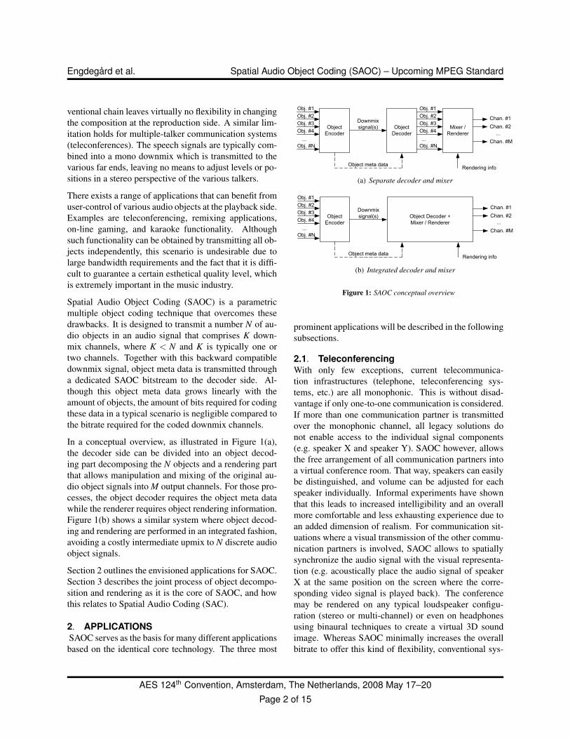
In a conceptual overview, as illustrated in Figure 1(a),the decoder side can be divided into an object decod-ing part decomposing the N objects and a rendering partthat allows manipulation and mixing of the original au-dio object signals into M output channels. For those pro-cesses, the object decoder requires the object meta datawhile the renderer requires object rendering information.Figure 1(b) shows a similar system where object decod-ing and rendering are performed in an integrated fashion,avoiding a costly intermediate upmix to N discrete audioobject signals.
Section 2 outlines the envisioned applications for SAOC.Section 3 describes the joint process of object decompo-sition and rendering as it is the core of SAOC, and howthis relates to Spatial Audio Coding (SAC).
2. APPLICATIONSSAOC serves as the basis for many different applicationsbased on the identical core technology. The three most
Object
Encoder
Downmix
signal(s) Object
Decoder
Obj. #1
Obj. #2
Obj. #3
Obj. #4
Obj. #N
...
Mixer /
Renderer
Chan. #1
Chan. #2
Chan. #M
...
Obj. #1
Obj. #2
Obj. #3
Obj. #4
Obj. #N
...
Object meta dataRendering info
(a) Separate decoder and mixer
Object
Encoder
Downmix
signal(s) Object Decoder +
Mixer / Renderer
Chan. #1
Chan. #2
Chan. #M
...
Obj. #1
Obj. #2
Obj. #3
Obj. #4
Obj. #N
...
Object meta dataRendering info
(b) Integrated decoder and mixer
Figure 1: SAOC conceptual overview
prominent applications will be described in the followingsubsections.
2.1. TeleconferencingWith only few exceptions, current telecommunica-tion infrastructures (telephone, teleconferencing sys-tems, etc.) are all monophonic. This is without disad-vantage if only one-to-one communication is considered.If more than one communication partner is transmittedover the monophonic channel, all legacy solutions donot enable access to the individual signal components(e.g. speaker X and speaker Y). SAOC however, allowsthe free arrangement of all communication partners intoa virtual conference room. That way, speakers can easilybe distinguished, and volume can be adjusted for eachspeaker individually. Informal experiments have shownthat this leads to increased intelligibility and an overallmore comfortable and less exhausting experience due toan added dimension of realism. For communication sit-uations where a visual transmission of the other commu-nication partners is involved, SAOC allows to spatiallysynchronize the audio signal with the visual representa-tion (e.g. acoustically place the audio signal of speakerX at the same position on the screen where the corre-sponding video signal is played back). The conferencemay be rendered on any typical loudspeaker configu-ration (stereo or multi-channel) or even on headphonesusing binaural techniques to create a virtual 3D soundimage. Whereas SAOC minimally increases the overallbitrate to offer this kind of flexibility, conventional sys-
AES 124th Convention, Amsterdam, The Netherlands, 2008 May 17–20Page 2 of 15
Engdegard et al. Spatial Audio Object Coding (SAOC) – Upcoming MPEG Standard
tems would require multiple transport channel capacity.Thus, SAOC allows for cost-effective implementation ofenhanced voice services. The SAOC side information isconveyed in a hidden, backward compatible way, allow-ing legacy terminals to decode the full communicationsignal without the additional SAOC functionality.
A different way of teleconferencing is the “voice chat”application in Massively Multiplayer Online gaming(MMO) or other social-oriented virtual worlds. In suchcontexts, there is typically already an IP based communi-cation framework available. In addition, the heart of thecommunication protocol between the players is their vir-tual coordinates used in the common game world. Thismakes it highly suitable to use SAOC as a spatial com-munication system. As the coordinates from other play-ers get combined with the user’s orientation, the nec-essary SAOC matrix parameters can easily be derived,and hence the voices of the players get rendered and re-alistically positioned in space. Inherently, such a sys-tem would support any playback configuration includinge.g. binaural, 5.1 or any other popular game audio setup.
2.2. Backwards Compatible Interactive Re-mixingThe SAOC technology is also perfectly suited for in-teractive re-mix applications. This means that mono orstereo content can be provided in arbitrary formats to theconsumer along with SAOC data describing the objectspresent in the mix. The user is now able to create his orher own remix of the music, or the sounds in the mix.SAOC allows managing the audio objects similarly tothat of a multi-track mixing desk such as: Adjusting therelative level, changing the spatial position and using ef-fects. In this way one can e.g.,
• Suppress / attenuate certain instruments for playingalong (karaoke type of applications)
• Modify the original track to reflect the user’s prefer-ence (e.g. “more drums and less strings” for a danceparty; “less drums and more vocals” for relax mu-sic). In case of many different objects it is also pos-sible to group and modify certain instrument classessimultaneously (e.g. the brass or percussions sectionin an orchestra).
• Choose between different vocal tracks (“femalelead vocal versus male lead vocal”)
For online music distribution, another interesting appli-cation is an upgrade service for existing customers of
music content. Similarly as MPEG Surround [1] mayoffer an upgrade option for the added value of multi-channel sound in a backwards compatible way, SAOCmay offer object modification features. A commercialservice for example, provides two types of downloads,the core content perfect for conventional listening, andan additional (small size) download, upgrading the corecontent with SAOC side information to enable a karaoketype of application.
In the context of broadcasting or movie playback SAOCallows the same flexibility as described above. In a typ-ical scenario the audio material comprises backgroundmusic or ambient sounds in combination with a dialog,narration or voice-over. Here, the user can for examplechange the level of the dialog with respect to the back-ground music and thereby increase the intelligibility ofthe dialog or voice-over. This is especially interestingfor users with hearing impairments or in case of play-back in an environment with a fairly high backgroundnoise level. As the use of mobile media such as DVB-H is emerging, the same content (i.e. the same audiomix) may be broadcast to the living room and to a mo-bile receiver in an urban noisy environment. This issue istypically addressed by such an SAOC enhancement ap-plication.
2.3. Gaming / Rich MediaFor rich media content, SAOC can be used exploitingits high compression efficiency and computationally effi-cient rendering. The applications of rich media are man-ifold as they span a wide scope ranging from interactiveaudio/visual interfaces to computer games. Typical ex-amples of such applications and platforms include Flashor Java based rich media platforms or mobile gaming ingeneral. On those platforms, the audio rendering capabil-ities are often kept on a simplistic level in order to limitcomplexity or data size. A legacy decoding/renderingsystem that handles many separate audio object streamsgets increasingly complex with a growing number of au-dio objects as every object needs its individual decoderinstance. Using SAOC technology, the complexity de-pends less on the number of objects since they are han-dled parametrically. The complexity of SAOC is es-sentially defined by the number of downmix and outputchannels, which is independent of the number of control-lable audio objects.
One of the main aspects of game audio is the interactiverendering of audio objects. Here SAOC can serve severalfunctions. Background music in games is often applied
AES 124th Convention, Amsterdam, The Netherlands, 2008 May 17–20Page 3 of 15
Engdegard et al. Spatial Audio Object Coding (SAOC) – Upcoming MPEG Standard
as interactive music, which is since long an importantconcept in gaming technology. The efficient representa-tion of object controllable (interactive) music that SAOCoffers results in small audio data size and low compu-tational complexity when the music is decoded and ren-dered. The handling of environmental sounds can alsobenefit from SAOC in a similar way, as they often areimplemented as short loops in order to save memory.
3. SAOC ARCHITECTURESpatial audio coding technology (such as MPEG Sur-
round as standardized in ISO/MPEG) [2, 1] recentlyopened up possibilities for a new paradigm of user-controllable manipulation. The resulting Spatial AudioObject Coding (SAOC) work item provides a wealth ofrendering flexibility based on transmission of a conven-tional mono or stereo downmix, extended with paramet-ric audio object side information that enables the de-sired flexibility. In January 2007, Moving Picture Ex-perts Group (MPEG) issued a Call for Proposals (CfP)for an SAOC system. After evaluation of the responsessix months later, a reference model zero (RM0) was cho-sen. Interestingly, the RM0 system re-uses MPEG Sur-round (MPS) as rendering engine using transcoding andeffects extensions. At the receiver side, an SAOC bit-stream containing the parametric audio object descrip-tion is transcoded into an MPS bitstream containing theparametric audio channel description. Another impor-tant input to this transcoder is the rendering matrix, de-scribing the (level) mapping from the audio objects tothe playback channels. This transcoder functionality iscomparable to an audio mixing console with the objectsignals at the inputs. The system also facilitates the in-tegration of insert- and sum-effects. Furthermore, theSAOC system provides a broad range of playback config-urations (inherited from MPEG Surround) including 7.1,5.1, binaural stereo and plain stereo. The various objectscan have a mono, stereo or a multi-channel format (so-called Multi-channel Background Objects, or MBOs).
3.1. Hybrid QMFAn essential part of the spatial audio technologies,
MPEG Surround as well as SAOC, are the Quadra-ture Mirror Filter (QMF) banks [3] which serve astime/frequency transform and are required to enable thefrequency selective processing. The QMF bank has nearalias-free behavior even when altering the gains of neigh-boring subbands excessively, which is a fundamental re-quirement for these systems.
The same QMF is also the native filterbank in SpectralBand Replication (SBR) [4, 5] and Parametric Stereo(PS) [6, 7]. SBR and PS are the vital enhancement toolsin the MPEG-4 HE-AAC (V2) codec, and by combin-ing SAOC with SBR one can further improve low bitrateperformance. Furthermore, all three cascaded post pro-cesses, SBR – SAOC – MPS can be done consecutivelyin the QMF domain, enwrapped by only one analysis andsynthesis stage, and hence allowing significant complex-ity savings. The SAOC-to-MPS transcoding becomesstraightforward and without quality loss as matching fil-ter banks are used.
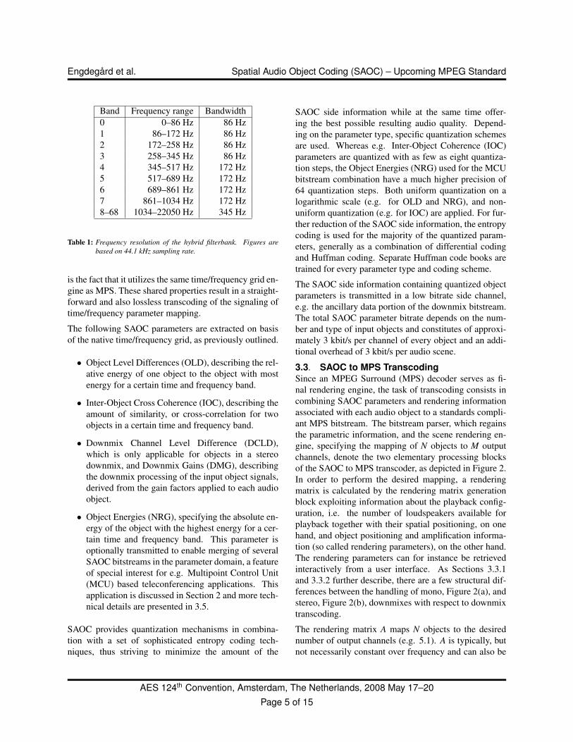
The 64 channel QMF bank offers linearly spaced fre-quency bands, hence the effective bandwidth for a sam-pling rate of 44.1 kHz is approximately 345 Hz per fre-quency band. At the lowest frequencies this resolution isfar lower than proposed bandwidth scales that take audi-tory perception into account, e.g. the Equivalent Rectan-gular Bandwidth (ERB) scale [8]. This motivates the in-troduction of a hybrid filterbank structure for use in para-metric channel extension methods [7], comprising addi-tional subband filtering for the lower QMF bands. Thecomplete hybrid filterbank achieves a good approxima-tion of the ERB scale with effective bandwidths of ap-proximately 86 Hz for the lowest bands up to the inher-ent 345 Hz for the upper bands. In Table 1, the frequencydivision of the hybrid filterbank is shown.
In order to reduce the amount of parameter data, it makessense to keep the frequency resolution for the upperrange lower than the native QMF bandwidth. Still fol-lowing the approximated ERB scale, the QMF bandshigher up in frequency are therefore grouped and aver-aged accordingly. This combined structure of frequencybands forms a 28 band base resolution, but can easily bescaled down to subsets by grouping neighboring bands.These bands are referred to as parameter bands.
3.2. SAOC ParametersAs taught in Section 3.1, the hybrid QMF bank is used
for enabling frequency selective processing of all param-eters. Each data frame of the SAOC bitstream containsone or more sets of parameters for each parameter band,where every set corresponds to a certain block of samplesin time. As in MPEG Surround the frequency resolutioncan be made dynamic by changing the number of param-eter bands to be coded. Also, the update rate can be madeadaptive, constituting a flexibly defined time/frequencygrid. An important feature of the SAOC parametrization
AES 124th Convention, Amsterdam, The Netherlands, 2008 May 17–20Page 4 of 15
Engdegard et al. Spatial Audio Object Coding (SAOC) – Upcoming MPEG Standard
Band Frequency range Bandwidth0 0–86 Hz 86 Hz1 86–172 Hz 86 Hz2 172–258 Hz 86 Hz3 258–345 Hz 86 Hz4 345–517 Hz 172 Hz5 517–689 Hz 172 Hz6 689–861 Hz 172 Hz7 861–1034 Hz 172 Hz8–68 1034–22050 Hz 345 Hz
Table 1: Frequency resolution of the hybrid filterbank. Figures arebased on 44.1 kHz sampling rate.
is the fact that it utilizes the same time/frequency grid en-gine as MPS. These shared properties result in a straight-forward and also lossless transcoding of the signaling oftime/frequency parameter mapping.
The following SAOC parameters are extracted on basisof the native time/frequency grid, as previously outlined.
• Object Level Differences (OLD), describing the rel-ative energy of one object to the object with mostenergy for a certain time and frequency band.
• Inter-Object Cross Coherence (IOC), describing theamount of similarity, or cross-correlation for twoobjects in a certain time and frequency band.
• Downmix Channel Level Difference (DCLD),which is only applicable for objects in a stereodownmix, and Downmix Gains (DMG), describingthe downmix processing of the input object signals,derived from the gain factors applied to each audioobject.
• Object Energies (NRG), specifying the absolute en-ergy of the object with the highest energy for a cer-tain time and frequency band. This parameter isoptionally transmitted to enable merging of severalSAOC bitstreams in the parameter domain, a featureof special interest for e.g. Multipoint Control Unit(MCU) based teleconferencing applications. Thisapplication is discussed in Section 2 and more tech-nical details are presented in 3.5.
SAOC provides quantization mechanisms in combina-tion with a set of sophisticated entropy coding tech-niques, thus striving to minimize the amount of the
SAOC side information while at the same time offer-ing the best possible resulting audio quality. Depend-ing on the parameter type, specific quantization schemesare used. Whereas e.g. Inter-Object Coherence (IOC)parameters are quantized with as few as eight quantiza-tion steps, the Object Energies (NRG) used for the MCUbitstream combination have a much higher precision of64 quantization steps. Both uniform quantization on alogarithmic scale (e.g. for OLD and NRG), and non-uniform quantization (e.g. for IOC) are applied. For fur-ther reduction of the SAOC side information, the entropycoding is used for the majority of the quantized param-eters, generally as a combination of differential codingand Huffman coding. Separate Huffman code books aretrained for every parameter type and coding scheme.
The SAOC side information containing quantized objectparameters is transmitted in a low bitrate side channel,e.g. the ancillary data portion of the downmix bitstream.The total SAOC parameter bitrate depends on the num-ber and type of input objects and constitutes of approxi-mately 3 kbit/s per channel of every object and an addi-tional overhead of 3 kbit/s per audio scene.
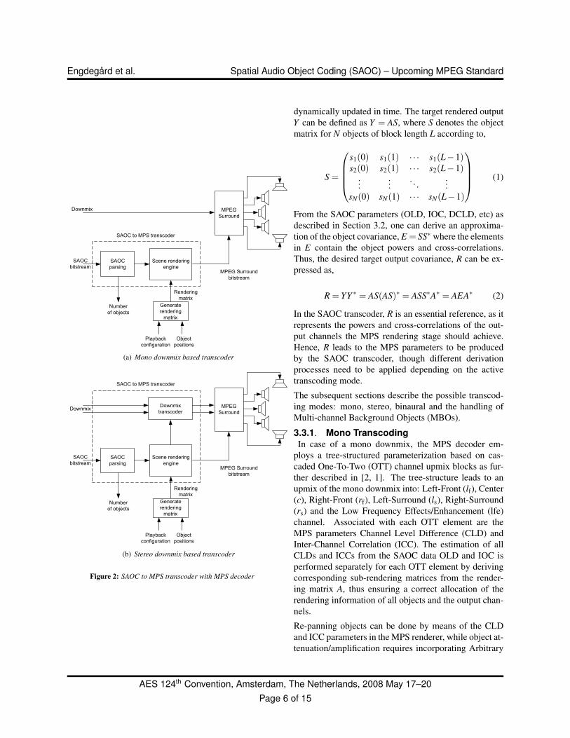
3.3. SAOC to MPS TranscodingSince an MPEG Surround (MPS) decoder serves as fi-nal rendering engine, the task of transcoding consists incombining SAOC parameters and rendering informationassociated with each audio object to a standards compli-ant MPS bitstream. The bitstream parser, which regainsthe parametric information, and the scene rendering en-gine, specifying the mapping of N objects to M outputchannels, denote the two elementary processing blocksof the SAOC to MPS transcoder, as depicted in Figure 2.In order to perform the desired mapping, a renderingmatrix is calculated by the rendering matrix generationblock exploiting information about the playback config-uration, i.e. the number of loudspeakers available forplayback together with their spatial positioning, on onehand, and object positioning and amplification informa-tion (so called rendering parameters), on the other hand.The rendering parameters can for instance be retrievedinteractively from a user interface. As Sections 3.3.1and 3.3.2 further describe, there are a few structural dif-ferences between the handling of mono, Figure 2(a), andstereo, Figure 2(b), downmixes with respect to downmixtranscoding.
The rendering matrix A maps N objects to the desirednumber of output channels (e.g. 5.1). A is typically, butnot necessarily constant over frequency and can also be
AES 124th Convention, Amsterdam, The Netherlands, 2008 May 17–20Page 5 of 15
Engdegard et al. Spatial Audio Object Coding (SAOC) – Upcoming MPEG Standard
MPEG
Surround
Downmix
Scene rendering
engine
SAOC
bitstreamMPEG Surround
bitstream
Playback
configuration
Rendering
matrix
Generate
rendering
matrix
Object
positions
SAOC
parsing
SAOC to MPS transcoder
Number
of objects
(a) Mono downmix based transcoder
MPEG
SurroundDownmix
Scene rendering
engine
SAOC
bitstreamMPEG Surround
bitstream
Playback
configuration
Rendering
matrix
Generate
rendering
matrix
Object
positions
SAOC
parsing
SAOC to MPS transcoder
Number
of objects
Downmix
transcoder
(b) Stereo downmix based transcoder
Figure 2: SAOC to MPS transcoder with MPS decoder
dynamically updated in time. The target rendered outputY can be defined as Y = AS, where S denotes the objectmatrix for N objects of block length L according to,
S =
s1(0) s1(1) · · · s1(L−1)s2(0) s2(1) · · · s2(L−1)
......
. . ....
sN(0) sN(1) · · · sN(L−1)
(1)
From the SAOC parameters (OLD, IOC, DCLD, etc) asdescribed in Section 3.2, one can derive an approxima-tion of the object covariance, E = SS∗ where the elementsin E contain the object powers and cross-correlations.Thus, the desired target output covariance, R can be ex-pressed as,
R = YY ∗ = AS(AS)∗ = ASS∗A∗ = AEA∗ (2)
In the SAOC transcoder, R is an essential reference, as itrepresents the powers and cross-correlations of the out-put channels the MPS rendering stage should achieve.Hence, R leads to the MPS parameters to be producedby the SAOC transcoder, though different derivationprocesses need to be applied depending on the activetranscoding mode.
The subsequent sections describe the possible transcod-ing modes: mono, stereo, binaural and the handling ofMulti-channel Background Objects (MBOs).
3.3.1. Mono TranscodingIn case of a mono downmix, the MPS decoder em-
ploys a tree-structured parameterization based on cas-caded One-To-Two (OTT) channel upmix blocks as fur-ther described in [2, 1]. The tree-structure leads to anupmix of the mono downmix into: Left-Front (lf), Center(c), Right-Front (rf), Left-Surround (ls), Right-Surround(rs) and the Low Frequency Effects/Enhancement (lfe)channel. Associated with each OTT element are theMPS parameters Channel Level Difference (CLD) andInter-Channel Correlation (ICC). The estimation of allCLDs and ICCs from the SAOC data OLD and IOC isperformed separately for each OTT element by derivingcorresponding sub-rendering matrices from the render-ing matrix A, thus ensuring a correct allocation of therendering information of all objects and the output chan-nels.
Re-panning objects can be done by means of the CLDand ICC parameters in the MPS renderer, while object at-tenuation/amplification requires incorporating Arbitrary
AES 124th Convention, Amsterdam, The Netherlands, 2008 May 17–20Page 6 of 15
Engdegard et al. Spatial Audio Object Coding (SAOC) – Upcoming MPEG Standard
Downmix Gains (ADGs) for a “virtual” modification ofthe downmix signal energy. ADG is a set of parameterspart of the MPS bitstream that specifies gain modifica-tion. They are defined for each time/frequency tile thatalso is used by the other parameters. The computationof the ADGs is based on the rendering matrix and theSAOC parameters OLD and DMG.
Considering the elements of the target covariance ma-trix R, extracting the MPS parameters (CLD, ICC, ADG)for the mono downmix case is trivial. The diagonal ele-ments rii representing the object powers, easily translateinto the objects’ absolute powers and channel distribu-tion, ADGs and CLDs. Furthermore, the off-diagonalelements ri j (i 6= j) translate into the ICC parameters cor-responding to the channel pair i and j.
3.3.2. Stereo TranscodingIn the stereo downmix case, the Two-To-Three (TTT)
channel upmix stage of MPS needs special considera-tions. The TTT process can be seen as a first order pre-dictor of the center downmix, where the center downmixcontains the center and LFE channel. In MPS, the Chan-nel Prediction Coefficients (CPCs), along with an ac-companying cross-correlation parameter describing theprediction loss, complete the mapping from the inputstereo downmix to the three channel set of a combinedleft downmix (lf + ls), a combined right downmix (rf +rs)and a combined center downmix (c+ lfe), thus represent-ing a left, right and center branch.
In an application where a part of the spectrum is codedwithout preserving phase information such as SpectralBand Replication (SBR) [4, 5], this frequency region canbe upmixed substituting the CPC based scheme with anupmix based on CLD parameters which is more robustagainst inter-channel phase distortion.
Even though MPEG Surround is an almost fully genericrendering engine, two issues need to be addressed by spe-cial techniques: Firstly, since MPEG Surround performsan energy preserving upmix process it is not straightfor-ward to apply the desired object gain values. However,the Arbitrary Downmix Gain (ADG) tool offers an ele-gant solution to this as outlined in Section 3.3.1. As thetranscoder converts object parameters to channel param-eters, the object gain values can be integrated into theADGs. It can be noted that by the method of transcodingthe object level parameters to the ADGs, the downmixsignal can remain untouched by the transcoder and di-rectly conveyed to the MPEG Surround decoder.
While this solution is adequate for the case where SAOCoperates in a mono downmix based configuration asshown in Figure 2(a), the stereo downmix based config-uration points to another issue. MPEG Surround, whenoperating in stereo downmix mode, expects the downmix(L0,R0) to be fixed and time invariant according to:
L0 = lf + αlb + βc (3)R0 = rf + αrb + βc (4)
where α and β are the constant downmix coefficientsusually set to α = β = 1/
√2. This basic downmix is
referred to as the ITU downmix [9]. Even though theADG tool has the freedom to alter the object gains, thereare no means to move objects between the left and rightbranches in the upmix tree. As an example, an objectthat is solely present in L0 can never be rendered to theright front or surround channel by MPS. To overcomethis limitation a stereo processor is converting the SAOCdownmix, (L0,R0) to a new modified downmix, (L′0,R
′0)
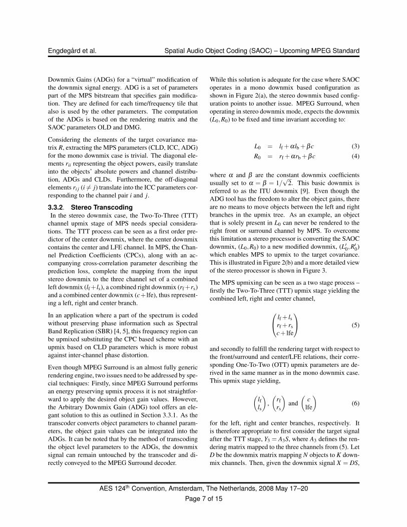
which enables MPS to upmix to the target covariance.This is illustrated in Figure 2(b) and a more detailed viewof the stereo processor is shown in Figure 3.
The MPS upmixing can be seen as a two stage process –firstly the Two-To-Three (TTT) upmix stage yielding thecombined left, right and center channel,
lf + lsrf + rsc + lfe
(5)
and secondly to fulfill the rendering target with respect tothe front/surround and center/LFE relations, their corre-sponding One-To-Two (OTT) upmix parameters are de-rived in the same manner as in the mono downmix case.This upmix stage yielding,
(lfls
),(
rfrs
)and
(c
lfe
)(6)
for the left, right and center branches, respectively. Itis therefore appropriate to first consider the target signalafter the TTT stage, Y3 = A3S, where A3 defines the ren-dering matrix mapped to the three channels from (5). LetD be the downmix matrix mapping N objects to K down-mix channels. Then, given the downmix signal X = DS,
AES 124th Convention, Amsterdam, The Netherlands, 2008 May 17–20Page 7 of 15
Engdegard et al. Spatial Audio Object Coding (SAOC) – Upcoming MPEG Standard
the prediction matrix C can approximate the target ren-dering:
CX ≈ Y3 (7)CDS ≈ A3S (8)
and hence C can be obtained by the least squares solutionand using the relation E = SS∗,
C ≈ A3ED∗(DED∗)−1 (9)
If A3 would be restricted to what is achievable with thenative TTT upmix function of MPS, then C would equalits corresponding TTT prediction matrix, CTTT, which in-cludes the parameters that need to be conveyed to theMPS decoder. However, for the general case the predic-tion matrix needs to be factorized into,
C = CTTTC2 (10)
where C2 is a downmix modifier, part of the stereo pro-cessor.
As shown in Figure 3, C2 is applied in the SAOC stereoprocessor while the CTTT matrix is sent to the MPS de-coder. C2 can be seen as the mixing matrix that assuresthe objects to be correctly positioned in a left-right per-spective. An example that clearly illustrates the impor-tance of the stereo processor is the case of a music/vocaldecomposition where vocals are mixed into L0 and thebackground music (without vocals) is mixed into R0.This mix which is, for direct listening slightly awkward,can be suitable for a karaoke application or any appli-cation where full separation of a certain audio object iscrucial. Here, a typical choice of C2 would be:
C2 =(
0.707 σL0.707 σR
)(11)
resulting in the vocals being positioned in (phantom)center and the background music would become up-mixed in a parametric stereo fashion using its left andright gain factors, derived from the corresponding CLDparameters (here denoted ∆L),
σ2L =
10∆L/10
1 + 10∆L/10 (12)
σ2R = 1−σ
2L (13)
However, upmixing with C2 does not necessarily lead tothe correct inter-channel cross-correlation of the back-ground music. For that reason, a signal from a decor-relator needs to be mixed into the output. The bottombranch in Figure 3 contains the creation and addition ofthe decorrelated signal through the pre-mix matrix Q,the decorrelation process h(n) and the post-mix matrixP. Here, Q and P are calculated to make the covariancematrix of the final output match the target covariance,(AEA∗), yielding a better match of the off-diagonal el-ements, i.e., the cross-correlations. The function of thedecorrelator is to output a signal orthogonal to the inputwith a similarly perceived character, spectral envelopeand subjective quality. The design of the decorrelationprocess, h(n), is technically related to artificial reverber-ators, but also includes special concerns due to the dy-namic mixing among other things, as discussed in [10].The stereo processor in the SAOC transcoder reuses thedecorrelator specified in MPS for efficient integration.
h(n)
C2
L0
R0
Q P
+
+
L'0
R'0
CTTT
lf + l
s
rf + r
s
c + lfe
SAOC stereo processor MPEG Surround decoder
Figure 3: Stereo downmix pre-processor
3.3.3. Binaural TranscodingHeadphones as reproduction device have gained signifi-cant interest during the last decade. Mobility and socialconstraints in most cases dictate headphones as a repro-duction device on mobile players. If conventional stereomaterial that was produced for loudspeaker playback isreproduced over headphones, the audio content is per-ceived inside the head [11, 12] due to the absence of theeffect of the acoustical pathway associated with a certainsound source position.
An approach that is often pursued to resolve the lackof ’out-of-head’ localization is to simulate a virtualloudspeaker setup over headphones by means of Head-
AES 124th Convention, Amsterdam, The Netherlands, 2008 May 17–20Page 8 of 15
Engdegard et al. Spatial Audio Object Coding (SAOC) – Upcoming MPEG Standard
Related Transfer Functions (HRTFs) [13, 14]. This ap-proach seems however suboptimal since it inherits alldrawbacks of loudspeaker systems having a limited num-ber of speakers and hence does not fully benefit from thefull 3D positioning freedom that in principle exists whenusing headphones [15].
One of the challenges for 3D sound reproduction onheadphones is the subject dependency of HRTFs [16, 17,18, 19]. It has been shown that incorporation of headmovement relaxes the requirements of using individual-ized HRTFs [20, 21, 22, 23]. Furthermore, especially inmobile devices, the large storage requirements for HRTFdatabases are undesirable [24].
To allow full flexibility in terms of HRTF databasespatial resolution and individualization, the SAOCtranscoder provides a parametric HRTF database inter-face rather than predefined HRTFs. This allows the im-plementer or end user to adapt the HRTF characteristicsas well as their spatial sampling according to the applica-tion at hand. The parametric approach ensures minimumstorage requirements for HRTFs given their compact rep-resentation [25]. The spatial positions for which HRTFsare available in the HRTF database can be freely selected,while SAOC objects can be mapped to any (combinationof) HRTFs present in that database. In accordance withthe method to map sound sources to channels for loud-speaker reproduction by means of a rendering matrix, the3D binaural mode employs the same concept to map ob-jects to HRTFs in the database. This method also allowsthe incorporation of head tracking by dynamically updat-ing the render matrix according to head movements.
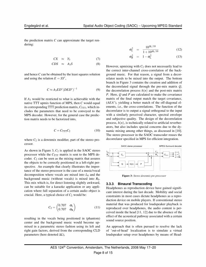
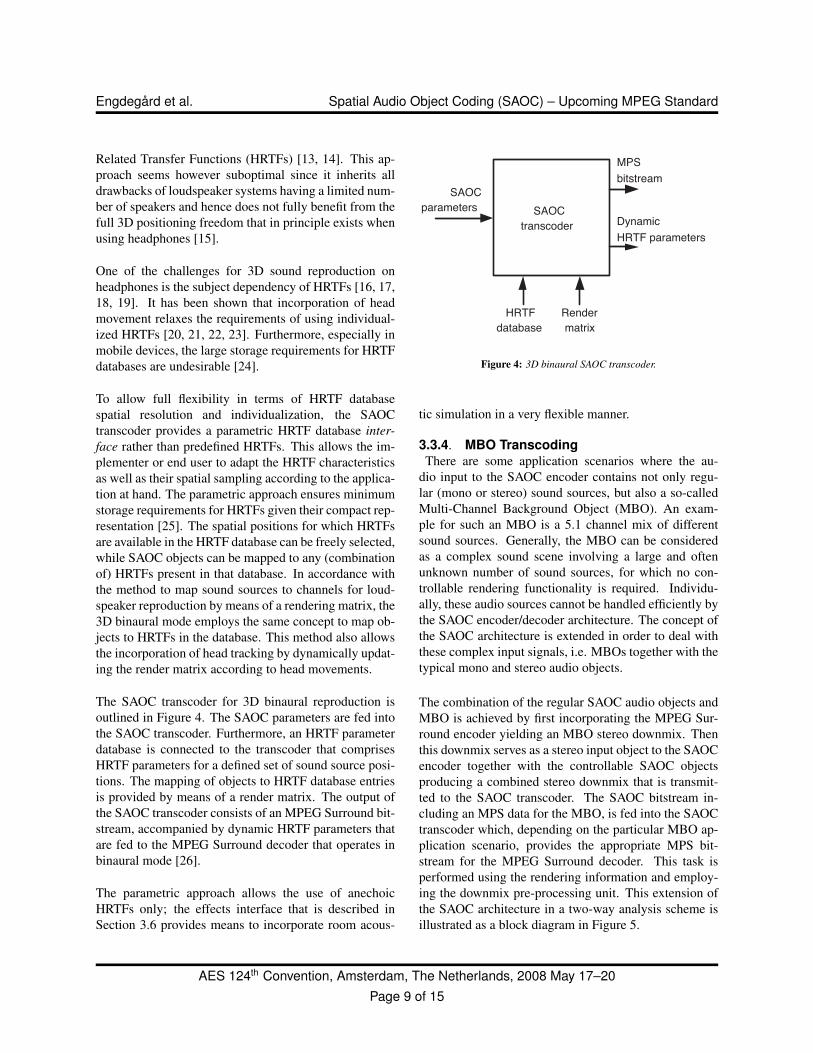
The SAOC transcoder for 3D binaural reproduction isoutlined in Figure 4. The SAOC parameters are fed intothe SAOC transcoder. Furthermore, an HRTF parameterdatabase is connected to the transcoder that comprisesHRTF parameters for a defined set of sound source posi-tions. The mapping of objects to HRTF database entriesis provided by means of a render matrix. The output ofthe SAOC transcoder consists of an MPEG Surround bit-stream, accompanied by dynamic HRTF parameters thatare fed to the MPEG Surround decoder that operates inbinaural mode [26].
The parametric approach allows the use of anechoicHRTFs only; the effects interface that is described inSection 3.6 provides means to incorporate room acous-
SAOC transcoder
SAOC parameters
HRTF database
Render matrix
MPS bitstream
Dynamic HRTF parameters
Figure 4: 3D binaural SAOC transcoder.
tic simulation in a very flexible manner.
3.3.4. MBO TranscodingThere are some application scenarios where the au-
dio input to the SAOC encoder contains not only regu-lar (mono or stereo) sound sources, but also a so-calledMulti-Channel Background Object (MBO). An exam-ple for such an MBO is a 5.1 channel mix of differentsound sources. Generally, the MBO can be consideredas a complex sound scene involving a large and oftenunknown number of sound sources, for which no con-trollable rendering functionality is required. Individu-ally, these audio sources cannot be handled efficiently bythe SAOC encoder/decoder architecture. The concept ofthe SAOC architecture is extended in order to deal withthese complex input signals, i.e. MBOs together with thetypical mono and stereo audio objects.
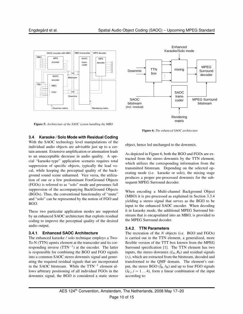
The combination of the regular SAOC audio objects andMBO is achieved by first incorporating the MPEG Sur-round encoder yielding an MBO stereo downmix. Thenthis downmix serves as a stereo input object to the SAOCencoder together with the controllable SAOC objectsproducing a combined stereo downmix that is transmit-ted to the SAOC transcoder. The SAOC bitstream in-cluding an MPS data for the MBO, is fed into the SAOCtranscoder which, depending on the particular MBO ap-plication scenario, provides the appropriate MPS bit-stream for the MPEG Surround decoder. This task isperformed using the rendering information and employ-ing the downmix pre-processing unit. This extension ofthe SAOC architecture in a two-way analysis scheme isillustrated as a block diagram in Figure 5.
AES 124th Convention, Amsterdam, The Netherlands, 2008 May 17–20Page 9 of 15
Engdegard et al. Spatial Audio Object Coding (SAOC) – Upcoming MPEG Standard
MPS decoder
MBOMPS
decoder
OBJ
SAOC
trans-coder
MBO transcoder
Rendering matrix
MPS
encoder
SAOC
encoder
MBO
FGO
Downmix
Bitstream
Downmix matrix
SAOC encoder with MBO
Figure 5: Architecture of the SAOC system handling the MBO
3.4. Karaoke / Solo Mode with Residual CodingWith the SAOC technology level manipulations of theindividual audio objects are advisable just up to a cer-tain amount. Extensive amplification or attenuation leadsto an unacceptable decrease in audio quality. A spe-cial “karaoke-type” application scenario requires totalsuppression of specific objects, typically the lead vo-cal, while keeping the perceptual quality of the back-ground sound scene unharmed. Vice versa, the utiliza-tion of one or a few predominant ForeGround Objects(FGOs) is referred to as “solo” mode and presumes fullsuppression of the accompanying BackGround Objects(BGOs). Thus, the conventional functionality of “mute”and “solo” can be represented by the notion of FGO andBGO.
These two particular application modes are supportedby an enhanced SAOC architecture that exploits residualcoding to improve the perceptual quality of the desiredaudio output.
3.4.1. Enhanced SAOC ArchitectureThe enhanced karaoke / solo technique employs a Two-To-N (TTN) upmix element at the transcoder and its cor-responding inverse (TTN−1) at the encoder. The latteris responsible for combining the BGO and FGO signalsinto a common SAOC stereo downmix signal and gener-ating the required residual signals that are incorporatedin the SAOC bitstream. While the TTN−1 element al-lows arbitrary positioning of all individual FGOs in thedownmix signal, the BGO is considered a static stereo
TTN box
mixing MPEG
Surround decoder
SAOC trans-coder
Downmix
SAOC bitstream
(incl. residual)
Renderingmatrix
Enhanced Karaoke/Solo mode
MPEG Surroundbitstream
Figure 6: The enhanced SAOC architecture
object, hence led unchanged to the downmix.
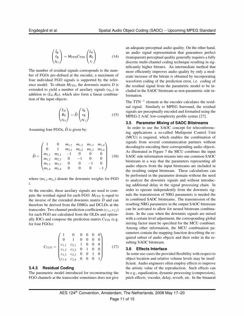
As depicted in Figure 6, both the BGO and FGOs are ex-tracted from the stereo downmix by the TTN element,which utilizes the corresponding information from thetransmitted bitstream. Depending on the selected op-erating mode (i.e. karaoke or solo), the mixing stageproduces a proper pre-processed downmix for the sub-sequent MPEG Surround decoder.
When encoding a Multi-channel Background Object(MBO) it is pre-processed as explained in Section 3.3.4yielding a stereo signal that serves as the BGO to beinput to the enhanced SAOC encoder. When decodingit in karaoke mode, the additional MPEG Surround bit-stream that is encapsulated into an MBO, is provided tothe MPEG Surround decoder.
3.4.2. TTN ParametersThe recreation of the N objects (i.e. BGO and FGOs)is carried out in the TTN element, a generalized, moreflexible version of the TTT box known from the MPEGSurround specification [1]. The TTN element has twoinputs, the stereo downmix (L0,R0) and residual signals(ri), which are extracted from the bitstream, decoded andtransformed to the QMF domain. The element’s out-put, the stereo BGO (lB, rB) and up to four FGO signals(sF,i, i = 1 . . .4), form a linear combination of the inputaccording to:
AES 124th Convention, Amsterdam, The Netherlands, 2008 May 17–20Page 10 of 15
Engdegard et al. Spatial Audio Object Coding (SAOC) – Upcoming MPEG Standard
lBrBsF,i
= MTTNCTTN
L0R0ri
(14)
The number of residual signals corresponds to the num-ber of FGOs pre-defined at the encoder, a maximum offour individual FGO signals is supported by the refer-ence model. To obtain MTTN, the downmix matrix D isextended to yield a number of auxilary signals (s0,i) inaddition to (L0,R0), which also form a linear combina-tion of the input objects:
L0R0s0,i
= D
lBrBsF,i
(15)
Assuming four FGOs, D is given by:
D =
1 0 m1,1 m1,2 m1,3 m1,40 1 m2,1 m2,2 m2,3 m2,4
m1,1 m2,1 −1 0 0 0m1,2 m2,2 0 −1 0 0m1,3 m2,3 0 0 −1 0m1,4 m2,4 0 0 0 −1
(16)
where (m1,i,m2,i) denote the downmix weights for FGOi.
At the encoder, these auxilary signals are used to com-pute the residual signal for each FGO. MTTN is equal tothe inverse of the extended downmix matrix D and cantherefore be derived from the DMGs and DCLDs at thetranscoder. Two channel prediction coefficients (c1,i,c2,i)for each FGO are calculated from the OLDs and option-ally IOCs and compose the prediction matrix CTTN (e.g.for four FGOs):
CT T N =
1 0 0 0 0 00 1 0 0 0 0
c1,1 c2,1 1 0 0 0c1,2 c2,2 0 1 0 0c1,3 c2,3 0 0 1 0c1,4 c2,4 0 0 0 1
(17)
3.4.3. Residual CodingThe parametric model introduced for reconstructing theFGO channels at the transcoder sometimes does not give
an adequate perceptual audio quality. On the other hand,an audio signal representation that guarantees perfect(transparent) perceptual quality generally requires a fullydiscrete multi-channel coding technique resulting in sig-nificantly higher bitrates. An intermediate method thatmore efficiently improves audio quality by only a mod-erate increase of the bitrate is obtained by incorporatingwaveform coding of the prediction error, i.e. coding ofthe residual signal from the parametric model to be in-cluded in the SAOC bitstream as non-parametric side in-formation.
The TTN−1 element at the encoder calculates the resid-ual signal. Similarly to MPEG Surround, the residualsignals are perceptually encoded and formatted using theMPEG-2 AAC low-complexity profile syntax [27].
3.5. Parameter Mixing of SAOC BitstreamsIn order to use the SAOC concept for teleconferenc-
ing applications a so-called Multipoint Control Unit(MCU) is required, which enables the combination ofsignals from several communication partners withoutdecoding/re-encoding their corresponding audio objects.As illustrated in Figure 7 the MCU combines the inputSAOC side information streams into one common SAOCbitstream in a way that the parameters representing allaudio objects from the input bitstreams are included inthe resulting output bitstream. These calculations canbe performed in the parameter domain without the needto analyze the downmix signals and without introduc-ing additional delay in the signal processing chain. Inorder to operate independently from the downmix sig-nals the transmission of NRG parameters is needed thein combined SAOC bitstreams. The transmission of theresulting NRG parameters in the output SAOC bitstreamcan be activated to allow for nested bitstream combina-tions. In the case when the downmix signals are mixedwith a certain level adjustment, the corresponding globalmixing factor must be specified for the MCU combiner.Among other information, the MCU combination pa-rameters contain the mapping function describing the re-quired subset of audio objects and their order in the re-sulting SAOC bitstream.
3.6. Effects InterfaceIn some use-cases the provided flexibility with respect toobject location and relative volume levels may be insuf-ficient. Audio engineers often employ effects to improvethe artistic value of the reproduction. Such effects canbe e.g., equalization, dynamic processing (compression),pitch effects, vocoder, delay, reverb, etc. In the binaural
AES 124th Convention, Amsterdam, The Netherlands, 2008 May 17–20Page 11 of 15
Engdegard et al. Spatial Audio Object Coding (SAOC) – Upcoming MPEG Standard
MCU parameters
MCU
combiner
downmix B
downmix A
bitstream A
bitstream B
combined downmix
combined bitstream
Figure 7: Outline of the MCU combiner
mode, the spatialization performance may benefit fromadditional reverberation as a complement to the anechoicbehavior of the parameterized HRTFs.
In audio processing two types of effects processing canbe discerned as shown in Figure 8. The first type, inserteffects, is applied serially to the signal chain. Whereasthe second effect type, send effects, creates a new parallelbus that can be fed by the mix of several signals. At alater stage the send effect bus (after effects processing)can be mixed together with other signals (or the mainbus). Hence, using the same concept as in traditionalmixing applications.
Insert effect
Send effect
Figure 8: Two types of effects processing.
In order to provide the receiving end with the means toapply a wide range of effects in a way similar to mix-ing consoles, an effects interface is provided that givesaccess to the objects in the SAOC stream for both typesof effect processing. Hence, SAOC provides handles toimplement effects processing in the system but does notprovide the effects itself.
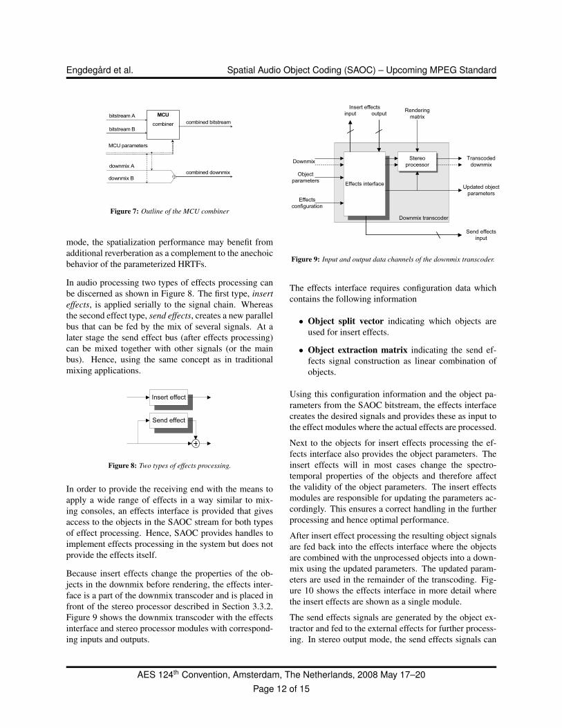
Because insert effects change the properties of the ob-jects in the downmix before rendering, the effects inter-face is a part of the downmix transcoder and is placed infront of the stereo processor described in Section 3.3.2.Figure 9 shows the downmix transcoder with the effectsinterface and stereo processor modules with correspond-ing inputs and outputs.
Downmix transcoder
Effects interface
Stereo processor
Send effects input
Downmix Transcoded downmix
Object parameters
Updated object parameters
Effects configuration
input output Rendering matrix
Insert effects
Figure 9: Input and output data channels of the downmix transcoder.
The effects interface requires configuration data whichcontains the following information
• Object split vector indicating which objects areused for insert effects.
• Object extraction matrix indicating the send ef-fects signal construction as linear combination ofobjects.
Using this configuration information and the object pa-rameters from the SAOC bitstream, the effects interfacecreates the desired signals and provides these as input tothe effect modules where the actual effects are processed.
Next to the objects for insert effects processing the ef-fects interface also provides the object parameters. Theinsert effects will in most cases change the spectro-temporal properties of the objects and therefore affectthe validity of the object parameters. The insert effectsmodules are responsible for updating the parameters ac-cordingly. This ensures a correct handling in the furtherprocessing and hence optimal performance.
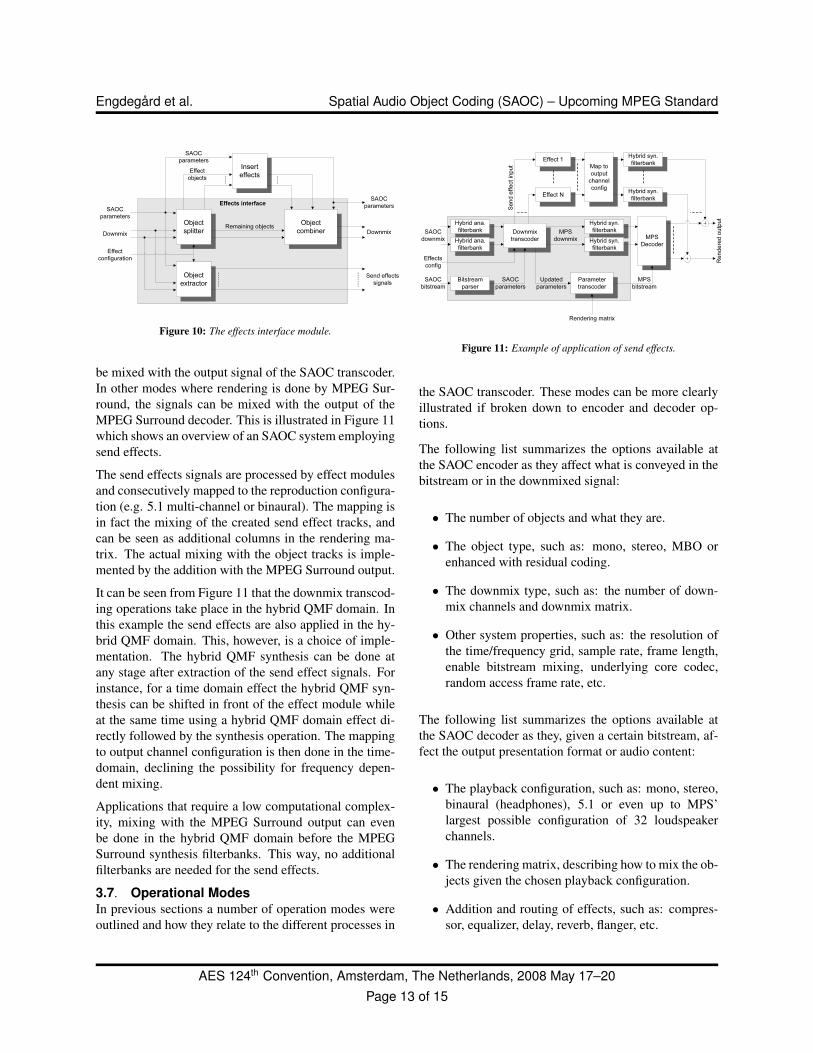
After insert effect processing the resulting object signalsare fed back into the effects interface where the objectsare combined with the unprocessed objects into a down-mix using the updated parameters. The updated param-eters are used in the remainder of the transcoding. Fig-ure 10 shows the effects interface in more detail wherethe insert effects are shown as a single module.
The send effects signals are generated by the object ex-tractor and fed to the external effects for further process-ing. In stereo output mode, the send effects signals can
AES 124th Convention, Amsterdam, The Netherlands, 2008 May 17–20Page 12 of 15
Engdegard et al. Spatial Audio Object Coding (SAOC) – Upcoming MPEG Standard
Effects interface
Objectsplitter
Object combiner
Insert effects
Downmix
SAOC parameters
SAOC parameters
Downmix
Objectextractor
Send effects signals
Remaining objects
Effect configuration
Effect objects
SAOC parameters
Figure 10: The effects interface module.
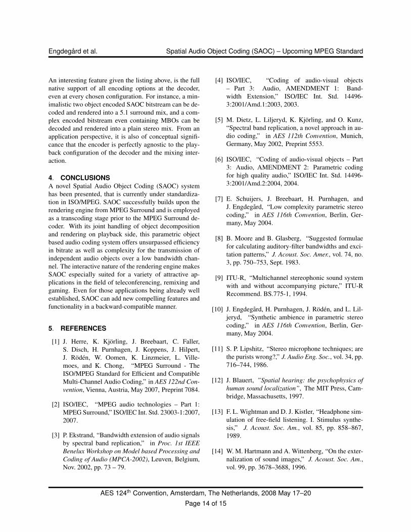
be mixed with the output signal of the SAOC transcoder.In other modes where rendering is done by MPEG Sur-round, the signals can be mixed with the output of theMPEG Surround decoder. This is illustrated in Figure 11which shows an overview of an SAOC system employingsend effects.
The send effects signals are processed by effect modulesand consecutively mapped to the reproduction configura-tion (e.g. 5.1 multi-channel or binaural). The mapping isin fact the mixing of the created send effect tracks, andcan be seen as additional columns in the rendering ma-trix. The actual mixing with the object tracks is imple-mented by the addition with the MPEG Surround output.
It can be seen from Figure 11 that the downmix transcod-ing operations take place in the hybrid QMF domain. Inthis example the send effects are also applied in the hy-brid QMF domain. This, however, is a choice of imple-mentation. The hybrid QMF synthesis can be done atany stage after extraction of the send effect signals. Forinstance, for a time domain effect the hybrid QMF syn-thesis can be shifted in front of the effect module whileat the same time using a hybrid QMF domain effect di-rectly followed by the synthesis operation. The mappingto output channel configuration is then done in the time-domain, declining the possibility for frequency depen-dent mixing.
Applications that require a low computational complex-ity, mixing with the MPEG Surround output can evenbe done in the hybrid QMF domain before the MPEGSurround synthesis filterbanks. This way, no additionalfilterbanks are needed for the send effects.
3.7. Operational ModesIn previous sections a number of operation modes wereoutlined and how they relate to the different processes in
Downmix transcoder
Effect 1
Effect N
MPS Decoder
Map to output channel config
Parameter transcoder
SAOC downmix
MPS downmix
SAOC bitstream
MPS bitstream
Rend
ered o
utput
Rendering matrix
Send
effec
t inpu
t
Hybrid ana. filterbank
Hybrid syn. filterbankHybrid syn. filterbank
Hybrid syn. filterbank
Hybrid syn. filterbank
Hybrid ana. filterbank
Effects config
Bitstream parser
SAOC parameters
Updated parameters
Figure 11: Example of application of send effects.
the SAOC transcoder. These modes can be more clearlyillustrated if broken down to encoder and decoder op-tions.
The following list summarizes the options available atthe SAOC encoder as they affect what is conveyed in thebitstream or in the downmixed signal:
• The number of objects and what they are.
• The object type, such as: mono, stereo, MBO orenhanced with residual coding.
• The downmix type, such as: the number of down-mix channels and downmix matrix.
• Other system properties, such as: the resolution ofthe time/frequency grid, sample rate, frame length,enable bitstream mixing, underlying core codec,random access frame rate, etc.
The following list summarizes the options available atthe SAOC decoder as they, given a certain bitstream, af-fect the output presentation format or audio content:
• The playback configuration, such as: mono, stereo,binaural (headphones), 5.1 or even up to MPS’largest possible configuration of 32 loudspeakerchannels.
• The rendering matrix, describing how to mix the ob-jects given the chosen playback configuration.
• Addition and routing of effects, such as: compres-sor, equalizer, delay, reverb, flanger, etc.
AES 124th Convention, Amsterdam, The Netherlands, 2008 May 17–20Page 13 of 15
Engdegard et al. Spatial Audio Object Coding (SAOC) – Upcoming MPEG Standard
An interesting feature given the listing above, is the fullnative support of all encoding options at the decoder,even at every chosen configuration. For instance, a min-imalistic two object encoded SAOC bitstream can be de-coded and rendered into a 5.1 surround mix, and a com-plex encoded bitstream even containing MBOs can bedecoded and rendered into a plain stereo mix. From anapplication perspective, it is also of conceptual signifi-cance that the encoder is perfectly agnostic to the play-back configuration of the decoder and the mixing inter-action.
4. CONCLUSIONSA novel Spatial Audio Object Coding (SAOC) systemhas been presented, that is currently under standardiza-tion in ISO/MPEG. SAOC successfully builds upon therendering engine from MPEG Surround and is employedas a transcoding stage prior to the MPEG Surround de-coder. With its joint handling of object decompositionand rendering on playback side, this parametric objectbased audio coding system offers unsurpassed efficiencyin bitrate as well as complexity for the transmission ofindependent audio objects over a low bandwidth chan-nel. The interactive nature of the rendering engine makesSAOC especially suited for a variety of attractive ap-plications in the field of teleconferencing, remixing andgaming. Even for those applications being already wellestablished, SAOC can add new compelling features andfunctionality in a backward-compatible manner.
5. REFERENCES
[1] J. Herre, K. Kjorling, J. Breebaart, C. Faller,S. Disch, H. Purnhagen, J. Koppens, J. Hilpert,J. Roden, W. Oomen, K. Linzmeier, L. Ville-moes, and K. Chong, “MPEG Surround - TheISO/MPEG Standard for Efficient and CompatibleMulti-Channel Audio Coding,” in AES 122nd Con-vention, Vienna, Austria, May 2007, Preprint 7084.
[2] ISO/IEC, “MPEG audio technologies – Part 1:MPEG Surround,” ISO/IEC Int. Std. 23003-1:2007,2007.
[3] P. Ekstrand, “Bandwidth extension of audio signalsby spectral band replication,” in Proc. 1st IEEEBenelux Workshop on Model based Processing andCoding of Audio (MPCA-2002), Leuven, Belgium,Nov. 2002, pp. 73 – 79.
[4] ISO/IEC, “Coding of audio-visual objects– Part 3: Audio, AMENDMENT 1: Band-width Extension,” ISO/IEC Int. Std. 14496-3:2001/Amd.1:2003, 2003.
[5] M. Dietz, L. Liljeryd, K. Kjorling, and O. Kunz,“Spectral band replication, a novel approach in au-dio coding,” in AES 112th Convention, Munich,Germany, May 2002, Preprint 5553.
[6] ISO/IEC, “Coding of audio-visual objects – Part3: Audio, AMENDMENT 2: Parametric codingfor high quality audio,” ISO/IEC Int. Std. 14496-3:2001/Amd.2:2004, 2004.
[7] E. Schuijers, J. Breebaart, H. Purnhagen, andJ. Engdegard, “Low complexity parametric stereocoding,” in AES 116th Convention, Berlin, Ger-many, May 2004.
[8] B. Moore and B. Glasberg, “Suggested formulaefor calculating auditory-filter bandwidths and exci-tation patterns,” J. Acoust. Soc. Amer., vol. 74, no.3, pp. 750–753, Sept. 1983.
[9] ITU-R, “Multichannel stereophonic sound systemwith and without accompanying picture,” ITU-RRecommend. BS.775-1, 1994.
[10] J. Engdegard, H. Purnhagen, J. Roden, and L. Lil-jeryd, “Synthetic ambience in parametric stereocoding,” in AES 116th Convention, Berlin, Ger-many, May 2004.
[11] S. P. Lipshitz, “Stereo microphone techniques; arethe purists wrong?,” J. Audio Eng. Soc., vol. 34, pp.716–744, 1986.
[12] J. Blauert, ”Spatial hearing: the psychophysics ofhuman sound localization”, The MIT Press, Cam-bridge, Massachusetts, 1997.
[13] F. L. Wightman and D. J. Kistler, “Headphone sim-ulation of free-field listening. I. Stimulus synthe-sis,” J. Acoust. Soc. Am., vol. 85, pp. 858–867,1989.
[14] W. M. Hartmann and A. Wittenberg, “On the exter-nalization of sound images,” J. Acoust. Soc. Am.,vol. 99, pp. 3678–3688, 1996.
AES 124th Convention, Amsterdam, The Netherlands, 2008 May 17–20Page 14 of 15
Engdegard et al. Spatial Audio Object Coding (SAOC) – Upcoming MPEG Standard
[15] J. Breebaart and E. Schuijers, “Why phantoms needto materialize on headphones,” IEEE Trans. On Au-dio, Speech and Language processing, p. Submit-ted, 2008.
[16] E. M. Wenzel, M. Arruda, D. J. Kistler, and F. L.Wightman, “Localization using nonindividualizedhead-related transfer functions,” J. Acoust. Soc.Am., vol. 94, pp. 111–123, 1993.
[17] A. Bronkhorst, “Localization of real and virtualsound sources,” J. Acoust. Soc. Am., vol. 98, pp.2542–2553, 1995.
[18] H. Møller, M. F. Sørensen, C. B. jensen, andD. Hammershøi, “Binaural technique: Do we needindividual recordings?,” J. Audio Eng. Soc., vol. 44,pp. 451–469, 1996.
[19] H. Møller, D. Hammershøi, C. B. Jensen, and M. F.Sørensen, “Evaluation of artifical heads in listen-ing tests,” J. Audio Eng. Soc., vol. 47, pp. 83–100,1999.
[20] F. L. Wightman and D. J. Kistler, “Resolution offront-back ambiguity in spatial hearing by listenerand source movement,” J. Acoust. Soc. Am., vol.105, pp. 2841–2853, 1999.
[21] D. R. Begault, E. M. Wenzel, and M. R. Anderson,“Direct comparison of the impact of head track-ing, reverberation, and individualized head-relatedtransfer functions on the spatial perception of a vir-tual speech source,” J. Audio Engineering Society,vol. 49, pp. 904–916, 2001.
[22] P. J. Minnaar, S. K. Olesen, F. Christensen, andH. Møller, “The importance of head movementsfor binaural room synthesis,” in Proc. ICAD, Es-poo, Finland, July 2001.
[23] P. Mackensen, Head movements, an additional cuein localization, Ph.D. thesis, Technische Universi-taet Berlin, Berlin, 2004.
[24] D. R. Begault, “Challenges to the successful im-plementation of 3-D sound,” J. Audio EngineeringSociety, vol. 39, 1991.
[25] J. Breebaart and C. Faller, ”Spatial audio pro-cessing: MPEG Surround and other applications”,John Wiley & Sons, Chichester, 2007.
[26] J. Breebaart, L. Villemoes, and K. Kjorling, “Bin-aural rendering in MPEG Surround,” EURASIP J.on Applied Signal Processing, vol. Accepted, 2008.
[27] M. Bosi, K. Brandenburg, S. Quackenbush,L. Fielder, K. Akagiri, H. Fuchs, M. Dietz, J. Herre,G. Davidson, and Oikawa, “ISO/IEC MPEG-2 Ad-vanced Audio Coding,” in J. Audio Eng. Soc., Oct.1997, Vol. 45, No. 10, pp. 789-814.
AES 124th Convention, Amsterdam, The Netherlands, 2008 May 17–20Page 15 of 15