Embed Size (px)
Citation preview
Audio Engineering Society
Convention PaperPresented at the 129th Convention
2010 November 4–7 San Francisco, CA, USA
The papers at this Convention have been selected on the basis of a submitted abstract and extended precis that havebeen peer reviewed by at least two qualified anonymous reviewers. This convention paper has been reproduced fromthe author’s advance manuscript, without editing, corrections, or consideration by the Review Board. The AES takesno responsibility for the contents. Additional papers may be obtained by sending request and remittance to Audio
Engineering Society, 60 East 42nd Street, New York, New York 10165-2520, USA; also see www.aes.org. All rightsreserved. Reproduction of this paper, or any portion thereof, is not permitted without direct permission from theJournal of the Audio Engineering Society.
Dynamic Motion of the CorrugatedRibbon in a Ribbon Microphone
Daniel Moses Schlessinger1, Jonathan S. Abel2
1Sennheiser DSP Research Laboratory, Palo Alto, CA, 94306 USA
2CCRMA, Department of Music, Stanford University, Stanford, CA, 94305 USA
Correspondence should be addressed to Daniel Schlessinger ([email protected])
ABSTRACTRibbon microphones are known for their warm sonics, owing in part to the unique ribbon motion inducedby the sound field. Here the motion of the corrugated ribbon element in a sound field is considered, anda physical model of the ribbon motion is presented. The model separately computes propagating torsionaldisturbances and coupled transverse and longitudinal disturbances. Each propagation mode is implementedas a mass-spring model where a mass is identified with a ribbon corrugation fold. The model is parameterizedusing ribbon material and geometric properties. Laser vibrometer measurements are presented, revealingstiffness in the transverse and longitudinal propagation, and showing close agreement between measured andmodeled ribbon motion.
1. INTRODUCTION
Ribbon microphones were among the first micro-phones developed [1], and are still sought after to-day. The unique sonics of ribbon microphones gaveus classic vocal recordings from the 1950’s, and manystill consider them to be an indispensable part of anyfull microphone locker [2]. Ribbon mics are oftendescribed as having a “warmth” or “smoothness,”which likely results from a combination of the fre-quency response and transducer nonlinearities.
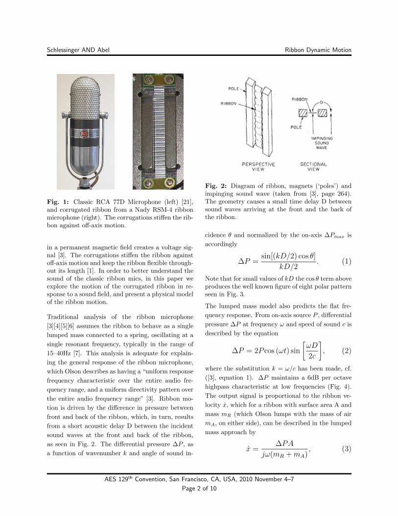
Designed by Harry Olson for RCA in the 1930s,early ribbon microphones such as the RCA 77 se-ries (Fig. 1) featured an aluminum ribbon havingan elongated rectangular design incorporating foldsor corrugations oriented perpendicular to the ribbonaxis [3]. This corrugated ribbon design can also befound in the classic Coles 4038 and the RCA44A.
The mechanism of the ribbon microphone is straight-forward: a thin metal filament is set in motion byincident sound waves, and the velocity of the ribbon
8215
Schlessinger AND Abel Ribbon Dynamic Motion
Fig. 1: Classic RCA 77D Microphone (left) [21],and corrugated ribbon from a Nady RSM-4 ribbonmicrophone (right). The corrugations stiffen the rib-bon against off-axis motion.
in a permanent magnetic field creates a voltage sig-nal [3]. The corrugations stiffen the ribbon againstoff-axis motion and keep the ribbon flexible through-out its length [1]. In order to better understand thesound of the classic ribbon mics, in this paper weexplore the motion of the corrugated ribbon in re-sponse to a sound field, and present a physical modelof the ribbon motion.
Traditional analysis of the ribbon microphone
[3][4][5][6] assumes the ribbon to behave as a single
lumped mass connected to a spring, oscillating at a
single resonant frequency, typically in the range of
15–40Hz [7]. This analysis is adequate for explain-
ing the general response of the ribbon microphone,
which Olson describes as having a “uniform response
frequency characteristic over the entire audio fre-
quency range, and a uniform directivity pattern over
the entire audio frequency range” [3]. Ribbon mo-
tion is driven by the difference in pressure between
front and back of the ribbon, which, in turn, results
from a short acoustic delay D between the incident
sound waves at the front and back of the ribbon,
as seen in Fig. 2. The differential pressure ∆P , as
a function of wavenumber k and angle of sound in-
Fig. 2: Diagram of ribbon, magnets (‘poles’) andimpinging sound wave (taken from [3], page 264).The geometry causes a small time delay D betweensound waves arriving at the front and the back ofthe ribbon.
cidence θ and normalized by the on-axis ∆Pmax is
accordingly
∆P =sin[(kD/2) cos θ]
kD/2. (1)
Note that for small values of kD the cos θ term aboveproduces the well known figure of eight polar patternseen in Fig. 3.
The lumped mass model also predicts the flat fre-
quency response. From on-axis source P , differential
pressure ∆P at frequency ω and speed of sound c is
described by the equation
∆P = 2P cos (ωt) sin
[ωD
2c
], (2)
where the substitution k = ω/c has been made, cf.
([3], equation 1). ∆P maintains a 6dB per octave
highpass characteristic at low frequencies (Fig. 4).
The output signal is proportional to the ribbon ve-
locity x, which for a ribbon with surface area A and
mass mR (which Olson lumps with the mass of air
mA, on either side), can be described in the lumped
mass approach by
x =∆PA
jω(mR +mA), (3)
AES 129th Convention, San Francisco, CA, USA, 2010 November 4–7
Page 2 of 10
Schlessinger AND Abel Ribbon Dynamic Motion
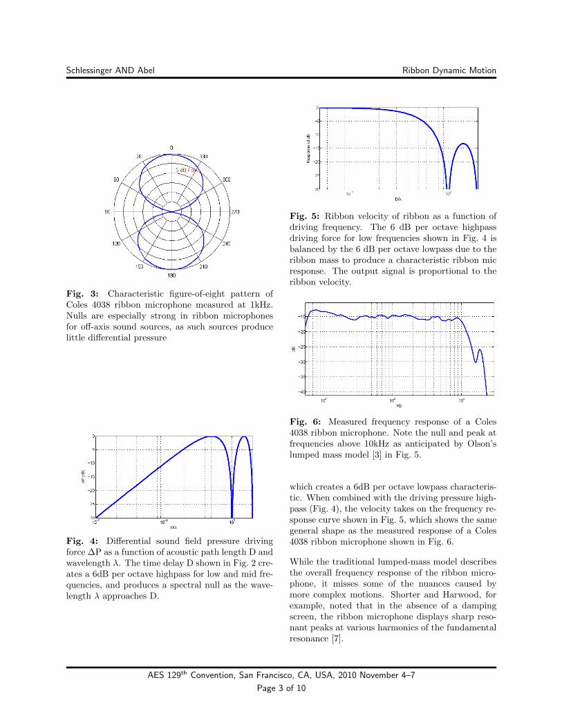
Fig. 3: Characteristic figure-of-eight pattern ofColes 4038 ribbon microphone measured at 1kHz.Nulls are especially strong in ribbon microphonesfor off-axis sound sources, as such sources producelittle differential pressure
Fig. 4: Differential sound field pressure drivingforce ∆P as a function of acoustic path length D andwavelength λ. The time delay D shown in Fig. 2 cre-ates a 6dB per octave highpass for low and mid fre-quencies, and produces a spectral null as the wave-length λ approaches D.
Fig. 5: Ribbon velocity of ribbon as a function ofdriving frequency. The 6 dB per octave highpassdriving force for low frequencies shown in Fig. 4 isbalanced by the 6 dB per octave lowpass due to theribbon mass to produce a characteristic ribbon micresponse. The output signal is proportional to theribbon velocity.
Fig. 6: Measured frequency response of a Coles4038 ribbon microphone. Note the null and peak atfrequencies above 10kHz as anticipated by Olson’slumped mass model [3] in Fig. 5.
which creates a 6dB per octave lowpass characteris-tic. When combined with the driving pressure high-pass (Fig. 4), the velocity takes on the frequency re-sponse curve shown in Fig. 5, which shows the samegeneral shape as the measured response of a Coles4038 ribbon microphone shown in Fig. 6.
While the traditional lumped-mass model describesthe overall frequency response of the ribbon micro-phone, it misses some of the nuances caused bymore complex motions. Shorter and Harwood, forexample, noted that in the absence of a dampingscreen, the ribbon microphone displays sharp reso-nant peaks at various harmonics of the fundamentalresonance [7].
AES 129th Convention, San Francisco, CA, USA, 2010 November 4–7
Page 3 of 10
Schlessinger AND Abel Ribbon Dynamic Motion
Physical models of microphones have been devel-oped in the past. Olson created models of manytypes of microphones, using analog circuit equiva-lents of many of the acoustic and mechanical com-ponents of microphones [4]. Leach[12] and Wells[13]use SPICE to implement circuit equivalents of mi-crophones. Roger Grinnip has recently created athorough finite-element model of a condenser mi-crophone, including in-depth behavior of the mem-brane, very accurately describes the microphone fre-quency response [8].
Bank and Hawksford [9][10], also employing finite el-ement methods, presented a model of a ribbon loud-speaker which was able to show harmonic resonantcharacteristics of the ribbon motor.
Julian David [11] has recently built upon the workof Richard Werner [5], describing the way that thetransformer and preamplifier actually alters the me-chanical behavior of the ribbon in a ribbon micro-phone, although still a lumped mass is used to de-scribe the basic mechanics of the ribbon.
In this paper we examine the ribbon motion in amore nuanced way. In Section 2, we consider themotion of each fold of the corrugated ribbon, andthe various degrees of freedom available to it. InSection 3, we present a physical model to describethe shape of the ribbon as it evolves over time. InSection 4, we verify the results of the model throughlaser vibrometer measurements, and make adjust-ments to the model to account for behavior foundin the measurements, specifically by incorporating astiffness term.
2. RIBBON MOTION
2.1. Ribbon Vibrational Modes
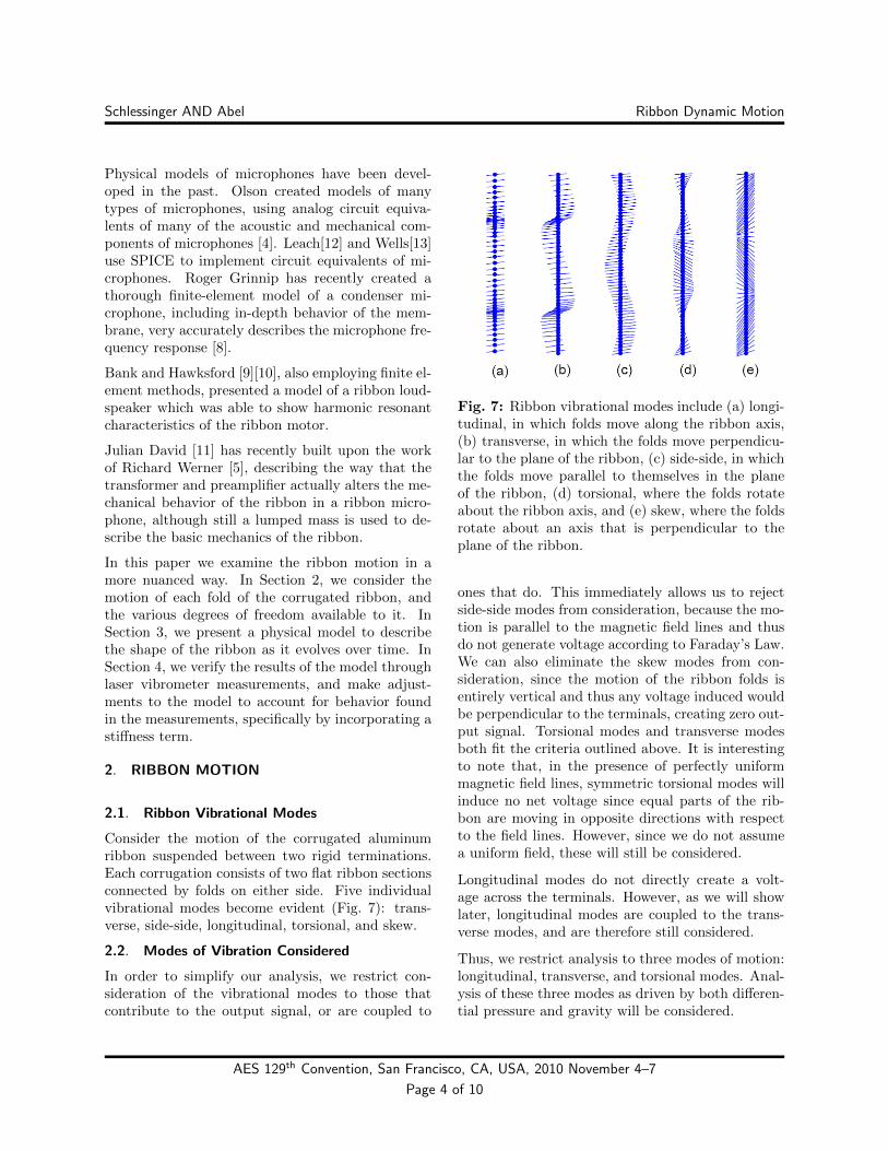
Consider the motion of the corrugated aluminumribbon suspended between two rigid terminations.Each corrugation consists of two flat ribbon sectionsconnected by folds on either side. Five individualvibrational modes become evident (Fig. 7): trans-verse, side-side, longitudinal, torsional, and skew.
2.2. Modes of Vibration Considered
In order to simplify our analysis, we restrict con-sideration of the vibrational modes to those thatcontribute to the output signal, or are coupled to
Fig. 7: Ribbon vibrational modes include (a) longi-tudinal, in which folds move along the ribbon axis,(b) transverse, in which the folds move perpendicu-lar to the plane of the ribbon, (c) side-side, in whichthe folds move parallel to themselves in the planeof the ribbon, (d) torsional, where the folds rotateabout the ribbon axis, and (e) skew, where the foldsrotate about an axis that is perpendicular to theplane of the ribbon.
ones that do. This immediately allows us to rejectside-side modes from consideration, because the mo-tion is parallel to the magnetic field lines and thusdo not generate voltage according to Faraday’s Law.We can also eliminate the skew modes from con-sideration, since the motion of the ribbon folds isentirely vertical and thus any voltage induced wouldbe perpendicular to the terminals, creating zero out-put signal. Torsional modes and transverse modesboth fit the criteria outlined above. It is interestingto note that, in the presence of perfectly uniformmagnetic field lines, symmetric torsional modes willinduce no net voltage since equal parts of the rib-bon are moving in opposite directions with respectto the field lines. However, since we do not assumea uniform field, these will still be considered.
Longitudinal modes do not directly create a volt-age across the terminals. However, as we will showlater, longitudinal modes are coupled to the trans-verse modes, and are therefore still considered.
Thus, we restrict analysis to three modes of motion:longitudinal, transverse, and torsional modes. Anal-ysis of these three modes as driven by both differen-tial pressure and gravity will be considered.
AES 129th Convention, San Francisco, CA, USA, 2010 November 4–7
Page 4 of 10
Schlessinger AND Abel Ribbon Dynamic Motion
3. RIBBON DYNAMICS MODEL
There are a few well known approaches for model-ing the motion of thin sheets of metal. One approachapplies a finite element methods, such as Bilbao, Ar-cas, and Chaigne used to model plate reverb [14][15].In their work, a discrete point of excitation was usedand the vibrations over time calculated at any pointon the membrane. This would also be similar to theribbon loudspeaker work by Bank and Hawksford[9],where the ribbon was modeled using a matrix oftiny mass-spring sheets, with the partial differen-tial equations discretized. However, we would haveto add spatial variations to account for the increasedhorizontal stiffness, nonuniform vertical propagationspeed (due to contoured corrugations), and set theside and top boundaries according to stiff and openterminations.
The approach that we have chosen offers an intu-itive interpretation of the pertinent parameters suchas the catenary ribbon shape due to gravity and thenominal corrugation distance. We separately con-sider the torsional mode and the coupled transverseand longitudinal modes, and present a mass-springmodel for each. In this way we hope to gain physicalinsight into the motion and output of the ribbon asit changes over time in a magnetic field.
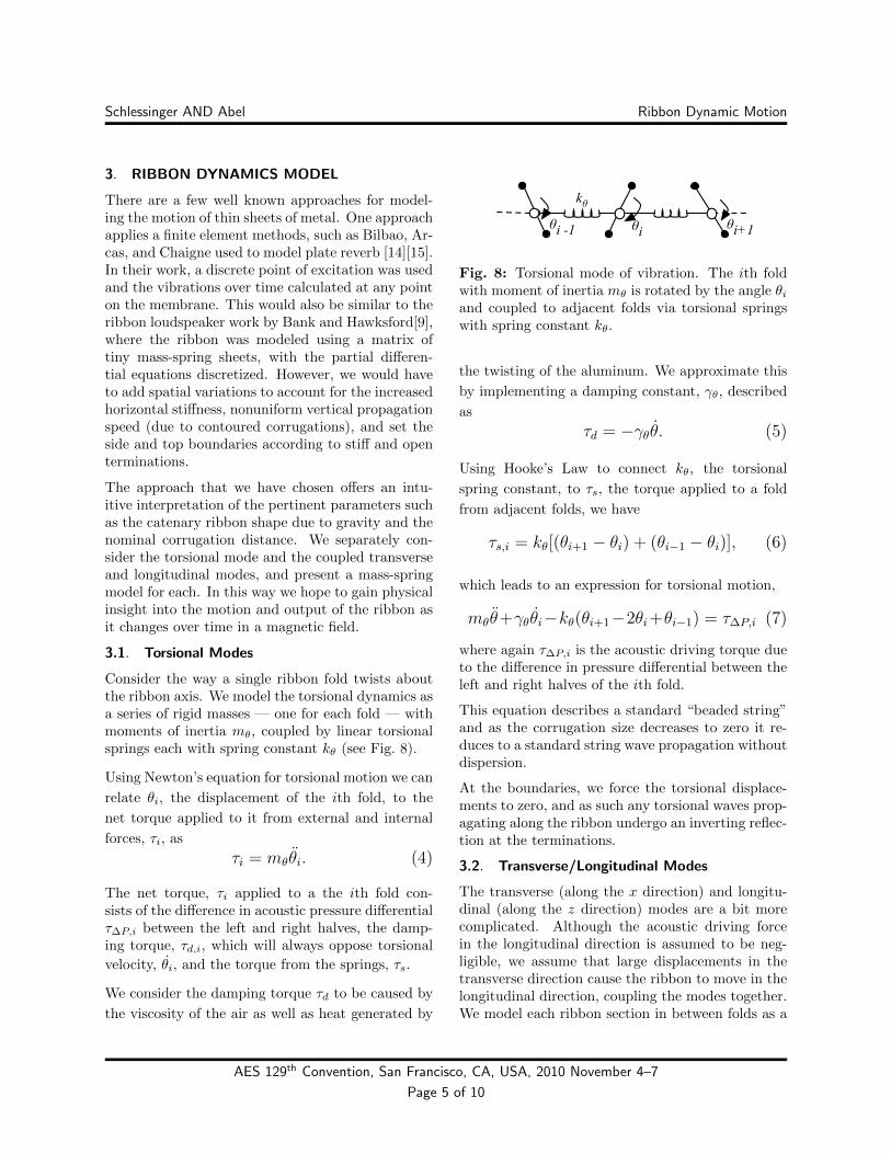
3.1. Torsional Modes
Consider the way a single ribbon fold twists aboutthe ribbon axis. We model the torsional dynamics asa series of rigid masses — one for each fold — withmoments of inertia mθ, coupled by linear torsionalsprings each with spring constant kθ (see Fig. 8).
Using Newton’s equation for torsional motion we can
relate θi, the displacement of the ith fold, to the
net torque applied to it from external and internal
forces, τi, as
τi = mθθi. (4)
The net torque, τi applied to a the ith fold con-sists of the difference in acoustic pressure differentialτ∆P,i between the left and right halves, the damp-ing torque, τd,i, which will always oppose torsional
velocity, θi, and the torque from the springs, τs.
We consider the damping torque τd to be caused by
the viscosity of the air as well as heat generated by
θi θi+1θi -1
kθ
Fig. 8: Torsional mode of vibration. The ith foldwith moment of inertia mθ is rotated by the angle θiand coupled to adjacent folds via torsional springswith spring constant kθ.
the twisting of the aluminum. We approximate this
by implementing a damping constant, γθ, described
as
τd = −γθθ. (5)
Using Hooke’s Law to connect kθ, the torsional
spring constant, to τs, the torque applied to a fold
from adjacent folds, we have
τs,i = kθ[(θi+1 − θi) + (θi−1 − θi)], (6)
which leads to an expression for torsional motion,
mθθ+γθθi−kθ(θi+1−2θi+θi−1) = τ∆P,i (7)
where again τ∆P,i is the acoustic driving torque dueto the difference in pressure differential between theleft and right halves of the ith fold.
This equation describes a standard “beaded string”and as the corrugation size decreases to zero it re-duces to a standard string wave propagation withoutdispersion.
At the boundaries, we force the torsional displace-ments to zero, and as such any torsional waves prop-agating along the ribbon undergo an inverting reflec-tion at the terminations.
3.2. Transverse/Longitudinal Modes
The transverse (along the x direction) and longitu-dinal (along the z direction) modes are a bit morecomplicated. Although the acoustic driving forcein the longitudinal direction is assumed to be neg-ligible, we assume that large displacements in thetransverse direction cause the ribbon to move in thelongitudinal direction, coupling the modes together.We model each ribbon section in between folds as a
AES 129th Convention, San Francisco, CA, USA, 2010 November 4–7
Page 5 of 10
Schlessinger AND Abel Ribbon Dynamic Motion
ξi-1
kξ
ξi+1
ξi = [xi, zi]Tx
z
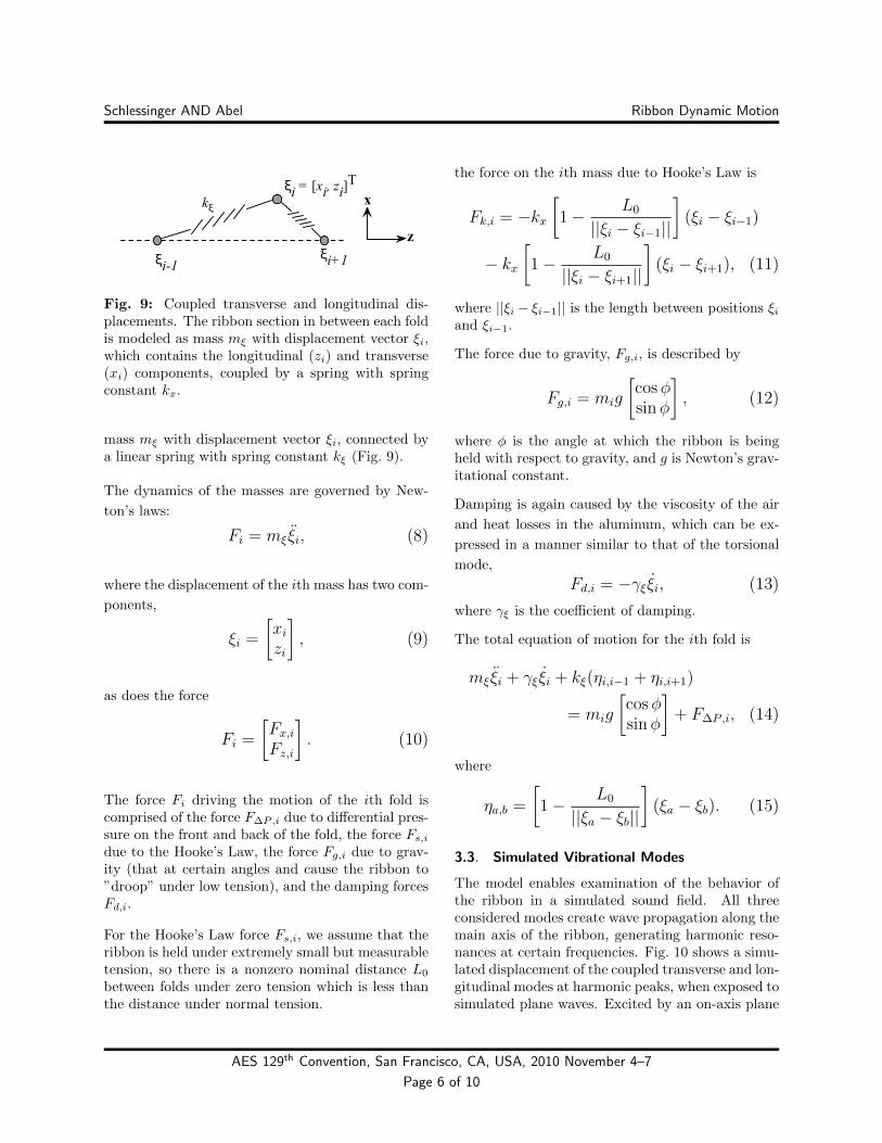
Fig. 9: Coupled transverse and longitudinal dis-placements. The ribbon section in between each foldis modeled as mass mξ with displacement vector ξi,which contains the longitudinal (zi) and transverse(xi) components, coupled by a spring with springconstant kx.
mass mξ with displacement vector ξi, connected bya linear spring with spring constant kξ (Fig. 9).
The dynamics of the masses are governed by New-
ton’s laws:
Fi = mξ ξi, (8)
where the displacement of the ith mass has two com-
ponents,
ξi =
[xizi
], (9)
as does the force
Fi =
[Fx,iFz,i
]. (10)
The force Fi driving the motion of the ith fold iscomprised of the force F∆P,i due to differential pres-sure on the front and back of the fold, the force Fs,idue to the Hooke’s Law, the force Fg,i due to grav-ity (that at certain angles and cause the ribbon to”droop” under low tension), and the damping forcesFd,i.
For the Hooke’s Law force Fs,i, we assume that theribbon is held under extremely small but measurabletension, so there is a nonzero nominal distance L0
between folds under zero tension which is less thanthe distance under normal tension.
the force on the ith mass due to Hooke’s Law is
Fk,i = −kx[1− L0
||ξi − ξi−1||
](ξi − ξi−1)
− kx[1− L0
||ξi − ξi+1||
](ξi − ξi+1), (11)
where ||ξi − ξi−1|| is the length between positions ξiand ξi−1.
The force due to gravity, Fg,i, is described by
Fg,i = mig
[cosφsinφ
], (12)
where φ is the angle at which the ribbon is beingheld with respect to gravity, and g is Newton’s grav-itational constant.
Damping is again caused by the viscosity of the air
and heat losses in the aluminum, which can be ex-
pressed in a manner similar to that of the torsional
mode,
Fd,i = −γξ ξi, (13)
where γξ is the coefficient of damping.
The total equation of motion for the ith fold is
mξ ξi + γξ ξi + kξ(ηi,i−1 + ηi,i+1)
= mig
[cosφsinφ
]+ F∆P ,i, (14)
where
ηa,b =
[1− L0
||ξa − ξb||
](ξa − ξb). (15)
3.3. Simulated Vibrational Modes
The model enables examination of the behavior ofthe ribbon in a simulated sound field. All threeconsidered modes create wave propagation along themain axis of the ribbon, generating harmonic reso-nances at certain frequencies. Fig. 10 shows a simu-lated displacement of the coupled transverse and lon-gitudinal modes at harmonic peaks, when exposed tosimulated plane waves. Excited by an on-axis plane
AES 129th Convention, San Francisco, CA, USA, 2010 November 4–7
Page 6 of 10
Schlessinger AND Abel Ribbon Dynamic Motion
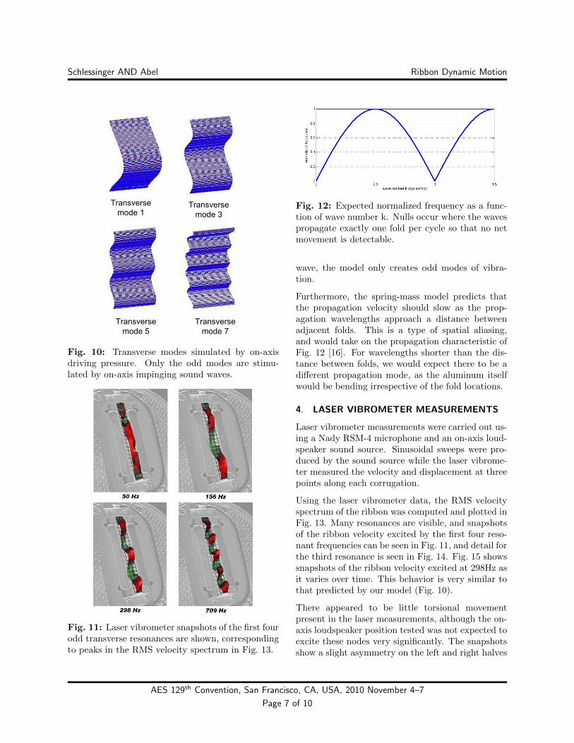
Fig. 10: Transverse modes simulated by on-axisdriving pressure. Only the odd modes are stimu-lated by on-axis impinging sound waves.
Fig. 11: Laser vibrometer snapshots of the first fourodd transverse resonances are shown, correspondingto peaks in the RMS velocity spectrum in Fig. 13.
Fig. 12: Expected normalized frequency as a func-tion of wave number k. Nulls occur where the wavespropagate exactly one fold per cycle so that no netmovement is detectable.
wave, the model only creates odd modes of vibra-tion.
Furthermore, the spring-mass model predicts thatthe propagation velocity should slow as the prop-agation wavelengths approach a distance betweenadjacent folds. This is a type of spatial aliasing,and would take on the propagation characteristic ofFig. 12 [16]. For wavelengths shorter than the dis-tance between folds, we would expect there to be adifferent propagation mode, as the aluminum itselfwould be bending irrespective of the fold locations.
4. LASER VIBROMETER MEASUREMENTS
Laser vibrometer measurements were carried out us-ing a Nady RSM-4 microphone and an on-axis loud-speaker sound source. Sinusoidal sweeps were pro-duced by the sound source while the laser vibrome-ter measured the velocity and displacement at threepoints along each corrugation.
Using the laser vibrometer data, the RMS velocityspectrum of the ribbon was computed and plotted inFig. 13. Many resonances are visible, and snapshotsof the ribbon velocity excited by the first four reso-nant frequencies can be seen in Fig. 11, and detail forthe third resonance is seen in Fig. 14. Fig. 15 showssnapshots of the ribbon velocity excited at 298Hz asit varies over time. This behavior is very similar tothat predicted by our model (Fig. 10).
There appeared to be little torsional movementpresent in the laser measurements, although the on-axis loudspeaker position tested was not expected toexcite these nodes very significantly. The snapshotsshow a slight asymmetry on the left and right halves
AES 129th Convention, San Francisco, CA, USA, 2010 November 4–7
Page 7 of 10
Schlessinger AND Abel Ribbon Dynamic Motion
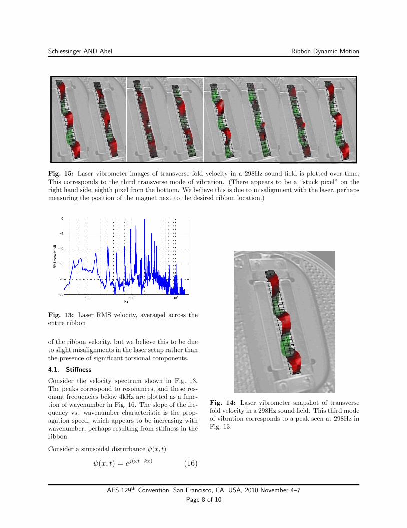
Fig. 15: Laser vibrometer images of transverse fold velocity in a 298Hz sound field is plotted over time.This corresponds to the third transverse mode of vibration. (There appears to be a “stuck pixel” on theright hand side, eighth pixel from the bottom. We believe this is due to misalignment with the laser, perhapsmeasuring the position of the magnet next to the desired ribbon location.)
Fig. 13: Laser RMS velocity, averaged across theentire ribbon
of the ribbon velocity, but we believe this to be dueto slight misalignments in the laser setup rather thanthe presence of significant torsional components.
4.1. Stiffness
Consider the velocity spectrum shown in Fig. 13.The peaks correspond to resonances, and these res-onant frequencies below 4kHz are plotted as a func-tion of wavenumber in Fig. 16. The slope of the fre-quency vs. wavenumber characteristic is the prop-agation speed, which appears to be increasing withwavenumber, perhaps resulting from stiffness in theribbon.
Consider a sinusoidal disturbance ψ(x, t)
ψ(x, t) = ej(ωt−kx) (16)
Fig. 14: Laser vibrometer snapshot of transversefold velocity in a 298Hz sound field. This third modeof vibration corresponds to a peak seen at 298Hz inFig. 13.
AES 129th Convention, San Francisco, CA, USA, 2010 November 4–7
Page 8 of 10
Schlessinger AND Abel Ribbon Dynamic Motion
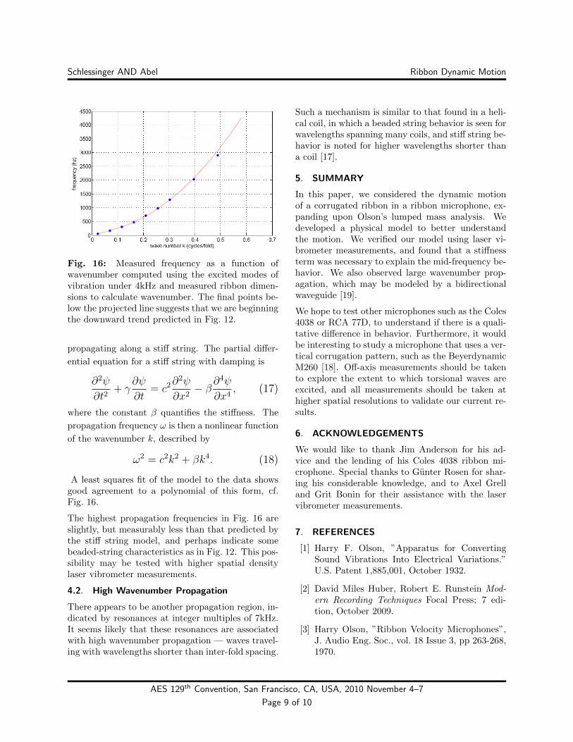
Fig. 16: Measured frequency as a function ofwavenumber computed using the excited modes ofvibration under 4kHz and measured ribbon dimen-sions to calculate wavenumber. The final points be-low the projected line suggests that we are beginningthe downward trend predicted in Fig. 12.
propagating along a stiff string. The partial differ-
ential equation for a stiff string with damping is
∂2ψ
∂t2+ γ
∂ψ
∂t= c2∂
2ψ
∂x2− β∂
4ψ
∂x4, (17)
where the constant β quantifies the stiffness. The
propagation frequency ω is then a nonlinear function
of the wavenumber k, described by
ω2 = c2k2 + βk4. (18)
A least squares fit of the model to the data showsgood agreement to a polynomial of this form, cf.Fig. 16.
The highest propagation frequencies in Fig. 16 areslightly, but measurably less than that predicted bythe stiff string model, and perhaps indicate somebeaded-string characteristics as in Fig. 12. This pos-sibility may be tested with higher spatial densitylaser vibrometer measurements.
4.2. High Wavenumber Propagation
There appears to be another propagation region, in-dicated by resonances at integer multiples of 7kHz.It seems likely that these resonances are associatedwith high wavenumber propagation — waves travel-ing with wavelengths shorter than inter-fold spacing.
Such a mechanism is similar to that found in a heli-cal coil, in which a beaded string behavior is seen forwavelengths spanning many coils, and stiff string be-havior is noted for higher wavelengths shorter thana coil [17].
5. SUMMARY
In this paper, we considered the dynamic motionof a corrugated ribbon in a ribbon microphone, ex-panding upon Olson’s lumped mass analysis. Wedeveloped a physical model to better understandthe motion. We verified our model using laser vi-brometer measurements, and found that a stiffnessterm was necessary to explain the mid-frequency be-havior. We also observed large wavenumber prop-agation, which may be modeled by a bidirectionalwaveguide [19].
We hope to test other microphones such as the Coles4038 or RCA 77D, to understand if there is a quali-tative difference in behavior. Furthermore, it wouldbe interesting to study a microphone that uses a ver-tical corrugation pattern, such as the BeyerdynamicM260 [18]. Off-axis measurements should be takento explore the extent to which torsional waves areexcited, and all measurements should be taken athigher spatial resolutions to validate our current re-sults.
6. ACKNOWLEDGEMENTS
We would like to thank Jim Anderson for his ad-vice and the lending of his Coles 4038 ribbon mi-crophone. Special thanks to Gunter Rosen for shar-ing his considerable knowledge, and to Axel Grelland Grit Bonin for their assistance with the laservibrometer measurements.
7. REFERENCES
[1] Harry F. Olson, ”Apparatus for ConvertingSound Vibrations Into Electrical Variations.”U.S. Patent 1,885,001, October 1932.
[2] David Miles Huber, Robert E. Runstein Mod-ern Recording Techniques Focal Press; 7 edi-tion, October 2009.
[3] Harry Olson, ”Ribbon Velocity Microphones”,J. Audio Eng. Soc., vol. 18 Issue 3, pp 263-268,1970.
AES 129th Convention, San Francisco, CA, USA, 2010 November 4–7
Page 9 of 10
Schlessinger AND Abel Ribbon Dynamic Motion
[4] Harry Olson, Applied Acoustics 2nd Ed., MaplePress Company, York, PA, 1934.
[5] Richard E. Werner, “On Electrical Loading ofMicrophones”, J. Audio Eng. Soc., Vol 3 Issue4, pp 194-197, 1955.
[6] L. L. Beranek, Acoustics Acoustical Society ofAmerica, Woodbury, NY, 1996.
[7] D.E.L. Shorter, H. D. Harwood, The Design ofa Ribbon Type Pressure-Gradient MicrophoneFor Broadcast Transmission, Research Dept.,BBC Engineering Division, 1955
[8] Roger S. Grinnip III, “Advanced Simulation ofa Condenser Microphone Capsule”, presentedat the 117th AES Convention, San Francisco,CA, 2004 Oct. 28-31.
[9] G. Bank, M.O.J. Hawksford, “Advances inComputer Modeling of Ribbon Loudspeakers”,presented at the 96th AES Convention, Ams-terdam, The Netherlands, 1994.
[10] G. Bank, M.O.J. Hawksford, “Comparisons be-tween the Measured and Computed Perfor-mance of Ribbon Loudspeakers”, presented atthe 100th AES Convention, Copenhagen, Den-mark, 1996.
[11] Julian David, “Analysis of the interaction be-tween ribbon motor, transformer, and pream-plifier and its application in ribbon microphonedesign”, presented at the 128th AES Conven-tion, London, UK 2010 May 22-25
[12] W. Marshall Leach, Jr., “Computer-AidedElectroacoustic Design with Spice”, J. AudioEng. Soc., Vol 39, No. 7/8, 1991 July/August
[13] Collin Wells, “Modeling Electret CondenserMicrophones in SPICE”, http://www.en-genius.net/site/zones/audiovideoZONE/technicalnotes/avt 030110, accessed Aug. 25th, 2010
[14] Stefan Bilbao, “A Digital Plate ReverberationAlgorithm”, J. Audio Eng. Soc., Vol. 55, No. 3,March 2007.
[15] A. Bilbao, K. Arcas, and A. Chaigne,“A Phys-ical Model for Plate Reverberation,” proceed-ings from the IEEE Int. Conference on Acous-tics, Speech and Signal Processing, vol. 5, pp.165-168, May 2006.
[16] Thomas D. Rossing, Neville H. Fletcher, Prin-ciples of Vibration and Sound, 2nd Ed.,Springer-Verlag, New York, 2004.
[17] L. Della Pietra and S. della Valle, On thedynamic behaviour of axially excited helicalsprings, Meccanica Volume 17, Number 1, 31-43, 1982.
[18] Michael Gayford, Microphone EngineeringHandbook, Focal Press, 1994
[19] J.O. Smith, Physical Audio Signal Process-ing http://ccrma.stanford.edu/ jos/pasp/, on-line book, accessed August 2010.
[20] Philip M. Morse and K. Uno Ingard, TheoreticalAcoustics, Princeton University Press, Prince-ton, NJ, 1968.
[21] Photo courtesy of Big “D” Broadcast exchangehttp://www.bigdmc.com/
AES 129th Convention, San Francisco, CA, USA, 2010 November 4–7
Page 10 of 10