Embed Size (px)
Citation preview

Audio Engineering Society
Convention Paper Presented at the 121st Convention
2006 October 5–8 San Francisco, CA, USA
This convention paper has been reproduced from the author's advance manuscript, without editing, corrections, or consideration by the Review Board. The AES takes no responsibility for the contents. Additional papers may be obtained by sending request and remittance to Audio Engineering Society, 60 East 42nd Street, New York, New York 10165-2520, USA; also see www.aes.org. All rights reserved. Reproduction of this paper, or any portion thereof, is not permitted without direct permission from the Journal of the Audio Engineering Society.
Frequency Domain Artificial Reverberation using Spectral Magnitude Decay
Earl Vickers1, Jian-Lung (Larry) Wu2, Praveen Gobichettipalayam Krishnan3, and Ravirala Narayana Karthik Sadanandam4
1 The Sound Guy, Inc., Seaside, CA 93955, USA [email protected]
2 Stanford Center for Computer Research in Music and Acoustics, Stanford, CA 94305, USA [email protected]
3 University of Missouri, Rolla, MO 65409, USA [email protected]
4 University of Missouri, Rolla, MO 65409, USA [email protected]
ABSTRACT
A novel method of producing artificial reverberation in the frequency domain, using spectral magnitude decay, is presented. The method involves accumulating the magnitudes of the short-time Fourier transform, based on the desired decay time as a function of frequency. Compared to time domain methods such as feedback delay networks, the current method requires less memory and provides independent control of the reverb energy and decay time in each frequency bin. Compared to convolution reverbs, the current approach offers flexible parametric control over the decay spectra and a computational cost that is independent of decay time.
1. INTRODUCTION
This paper presents a method for producing artificial late reverberation in the frequency domain using spectral magnitude decay. This method offers a different set of tradeoffs compared to previous reverberation methods such as time domain feedback loops and convolution reverbs.
Late reverberation refers to the diffuse portion of the room response (typically starting around 100 ms.), characterized by a very large number of echoes and an intensity that is relatively independent of the position within the room [1]. Late reverberation lends itself to a statistical description.
AES

Vickers et al Frequency Domain Artificial Reverberation
AES 121st Convention, San Francisco, CA, USA, 2006 October 5–8
Page 2 of 15
Time domain reverb algorithms, such as feedback delay networks [2], simulate late reverberation at a low computational cost while providing independent control over a number of perceptually relevant parameters. The reverb decay envelope can be made frequency dependent; however, due to the expense of placing multi-band equalizers in each feedback path, usually only two or three bands of decay time control are provided.
Convolution reverbs, typically implemented in the frequency domain, convolve a source signal with a desired impulse response. Convolution produces an excellent simulation of the acoustics of a particular physical space, but it lacks some of the flexibility of the time domain algorithms; also, the computational cost is greater, especially for long decay times.
The current approach is inspired partly by the observation that frequency domain time-scaling based on the phase vocoder often suffers from an unwanted “phasiness,” reverberation, or “loss of presence” [3]. Given that we are trying to produce reverberation, this side effect of the phase vocoder might prove to be an advantage, or at least not a liability. Our approach is also inspired by Moorer’s observation that “the responses in the finest concert halls sounded remarkably similar to white noise with an exponential amplitude envelope” [4].
Our algorithm, performed in the short-time Fourier transform (STFT) domain, attenuates and accumulates the spectral magnitudes, which are combined with a computed phase signal. This method yields an impulse response with a smooth, exponentially decaying envelope and independent control over room energy and decay time at each frequency.
The current method requires less memory than feedback delay networks, and, unlike convolution reverbs, it can produce extremely long reverb decay times at no additional computational cost.
We will discuss reverberation in the context of a number of related topics: time-scaling, time-freezing, magnitude accumulation and phase coherence. We will also discuss possible directions for future research.
2. THE STFT AND THE PHASE VOCODER
Given that we wish to extend the temporal evolution of a signal while retaining independent control over its
spectral content, our basic tool will be the phase vocoder [5], which allows a signal to be analyzed into a time-frequency grid, optionally modified in various ways, and resynthesized, as shown in Figure 1.
Figure 1: Phase Vocoder.
The phase vocoder can be efficiently implemented using the STFT [6]. An overview of two complementary views of the phase vocoder, the filter bank interpretation and the Fourier transform interpretation, are given in [7]. Some practical implementation details are provided in [8] and [9].
A common application of the phase vocoder is to implement time-scaling while preserving the pitch and spectra. To review, this is done as follows [10]:
1. Compute the STFT of the input signal.
X ta
u,!k( ) = h n( )x ta
u + n( )e" j!k nn="#
#
$ , where
x is the input signal, X is the input’s STFT representation,
h n( ) is the analysis window,

Vickers et al Frequency Domain Artificial Reverberation
AES 121st Convention, San Francisco, CA, USA, 2006 October 5–8
Page 3 of 15
!k
=2!k
N is the center frequency of the kth vocoder
channel (or bin), N is the size of the discrete Fourier transform, Ra
is the analysis hop size in samples, u is a set of successive integers starting at 0, and
ta
u= uR
a is the time of the uth analysis frame.
2. For each channel k and analysis time-instant ta
u ,
(a) Obtain the phase !k(ta
u)=!X(t
a
u,"
k) ,
(b) Calculate the heterodyned phase increment
!"
k
u= !
k(ta
u)#!
k(ta
u#1)#R
a$
k
(c) Take its principal determination (between !± ), denoted by u
kp!" , which can be regarded as the amount of frequency deviation from
k! ,
(d) Estimate the instantaneous frequency, u
kp
a
k
u
akR
t !"+#= 1)($̂ ,
(e) Set the phase of the time-stretched STFT at synthesis time uRt
s
u
s= , where
sR is the
synthesis hop size, according to the phase-propagation formula,
)(ˆ),(),( 1 u
aksk
u
sk
u
stRtYtY !+"#="# $ ,
(f) Set the magnitude ),(),(k
u
ak
u
stXtY !=! ,
(g) Obtain the output signal by overlap-adding the IDFTs of the synthesis frames ),(
k
u
stY ! , as
follows:
y(n)= w n! t
s
u( )u=!"
"
# yun! t
s
u( ) , where
yu (n)=
1
NY
k=0
N!1
" tsu,#k( )e j#k n
3. TIME-FREEZE, TIME-SCALING, LOOPING AND REVERBERATION
“In Babylonian mythology there are hints of a specially constructed room in one of the ziggurats where whispers stayed forever.” [11]
Our language suggests that there is something about reverberation that echoes, resonates and reverberates deep within the human psyche. One motivation for the current research is to find ways to produce long or infinite reverberant decays [12] that sound extremely smooth, as if the original sound were “frozen in mid-air.”
To begin with, we will consider modifying techniques used for time-scaling, time-freezing, and the creation of perceptually smooth loops for extending the sustain portion of musical notes, as used in sampling keyboards and software programs [13].
3.1. Time-Freeze
If we temporarily ignore certain time domain effects of reverberation, such as the diffusion of individual echoes, the spectral effects of reverberation are similar to what might be achieved by ‘freezing’ each STFT input frame and imposing a frequency-dependent decay on the spectral magnitudes.
Time-freezing, or infinite time-scaling, involves extending the magnitude spectrum of an STFT frame indefinitely while propagating the phases based on instantaneous frequency estimates. A number of papers have described phase-vocoder-based time-scaling [7, 14] and various improvements intended to reduce the aforementioned phasiness artifacts [10, 15]. Some techniques for freezing time are mentioned in [15] and [16], including the idea of alternating between input hops of +1 and -1 samples in consecutive frames.
A simple time-freeze algorithm is shown in Figure 2.

Vickers et al Frequency Domain Artificial Reverberation
AES 121st Convention, San Francisco, CA, USA, 2006 October 5–8
Page 4 of 15
Figure 2: Time-Freeze algorithm.
Immediately prior to freezing the sound, we capture the phase deltas for each frequency channel k ,
!!k t f( ) = !k t f( )"!k t f"1( ) , where t f denotes the
time of the frame immediately preceding the time freeze.
Then, at each time tu
, we apply a frequency-dependent
gain,
!
g "k( ) , to the magnitudes:
Y tu ,!k( ) = g !k( ) Y tu"1,!k( ) ,
increment the phases:
!Y tu ,"k( ) =!Y tu#1,"k( )+$!k t f( ) ,
and convert the magnitude-phase representation back into a rectangular representation:
Y t
u,!
k( ) = Y t
u,!
k( ) ei"Y tu ,!k( )
Then we perform inverse Fourier transforms and overlap-add as before. The resulting time-frozen signal has a frequency-dependent decay time (which can be infinite if the feedback gains are initialized to unity).
The output sounds smooth and ‘frozen.’ However, the result is perceived as artificial and mechanical, largely because the phase increment is exactly the same from one frame to the next, without the frequency modulations typical of musical sounds, and with none of the random phase fluctuations expected from true reverberation. The output from unvoiced or other noise-like signals can sound especially unnatural because coherent periodicities are imposed upon the entire duration of the time-freeze, resulting in ‘tonal noise.’
3.2. Ongoing Parallel Time-Freeze
The above process simulates the application of a reverb-like decay to a single audio frame. To apply this effect to an ongoing audio signal, one might imagine the following procedure: begin a new time-freeze process in parallel for each successive input frame (applying a frequency-dependent decay to the spectral magnitudes), and sum the time-aligned outputs. (See Figure 3.) The resulting structure is somewhat analogous in form to a multi-tapped delay line, i.e., the canonical reverb structure.
Vickers et al Frequency Domain Artificial Reverberation
AES 121st Convention, San Francisco, CA, USA, 2006 October 5–8
Page 5 of 15
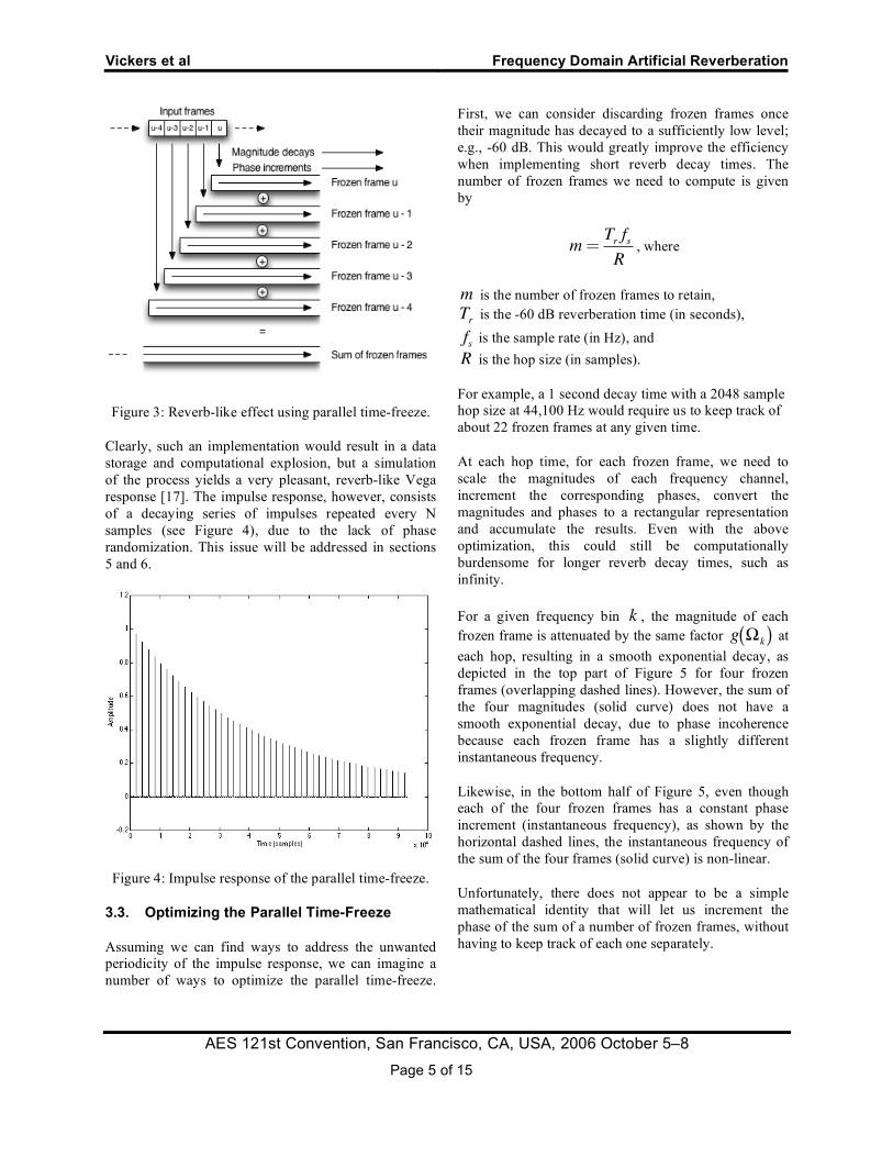
Figure 3: Reverb-like effect using parallel time-freeze.
Clearly, such an implementation would result in a data storage and computational explosion, but a simulation of the process yields a very pleasant, reverb-like Vega response [17]. The impulse response, however, consists of a decaying series of impulses repeated every N samples (see Figure 4), due to the lack of phase randomization. This issue will be addressed in sections 5 and 6.
Figure 4: Impulse response of the parallel time-freeze.
3.3. Optimizing the Parallel Time-Freeze
Assuming we can find ways to address the unwanted periodicity of the impulse response, we can imagine a number of ways to optimize the parallel time-freeze.
First, we can consider discarding frozen frames once their magnitude has decayed to a sufficiently low level; e.g., -60 dB. This would greatly improve the efficiency when implementing short reverb decay times. The number of frozen frames we need to compute is given by
m =Tr fs
R, where
m is the number of frozen frames to retain, Tr
is the -60 dB reverberation time (in seconds), fs is the sample rate (in Hz), and R is the hop size (in samples).
For example, a 1 second decay time with a 2048 sample hop size at 44,100 Hz would require us to keep track of about 22 frozen frames at any given time.
At each hop time, for each frozen frame, we need to scale the magnitudes of each frequency channel, increment the corresponding phases, convert the magnitudes and phases to a rectangular representation and accumulate the results. Even with the above optimization, this could still be computationally burdensome for longer reverb decay times, such as infinity.
For a given frequency bin k , the magnitude of each frozen frame is attenuated by the same factor
!
g "k( ) at each hop, resulting in a smooth exponential decay, as depicted in the top part of Figure 5 for four frozen frames (overlapping dashed lines). However, the sum of the four magnitudes (solid curve) does not have a smooth exponential decay, due to phase incoherence because each frozen frame has a slightly different instantaneous frequency.
Likewise, in the bottom half of Figure 5, even though each of the four frozen frames has a constant phase increment (instantaneous frequency), as shown by the horizontal dashed lines, the instantaneous frequency of the sum of the four frames (solid curve) is non-linear.
Unfortunately, there does not appear to be a simple mathematical identity that will let us increment the phase of the sum of a number of frozen frames, without having to keep track of each one separately.

Vickers et al Frequency Domain Artificial Reverberation
AES 121st Convention, San Francisco, CA, USA, 2006 October 5–8
Page 6 of 15
Figure 5: Magnitude (top) and instantaneous frequency (bottom) of frequency bin 13 for four adjacent frozen frames (dashed lines) and the sum of the four frozen
frames (curved solid lines). Note that the instantaneous frequency values tend to become extreme when the
corresponding magnitudes reach minima.
However, the idea of applying magnitude attenuation and phase increments to each frozen frame independently is an artificial construct to begin with, so it may be no more arbitrary to apply them to the sum of the frozen frames, if we can find a way to calculate a suitable phase increment (possibly based on a magnitude-weighted average of the instantaneous frequencies of the individual frozen frames). Alternatively, we may be able to consolidate groups of frames having similar instantaneous frequencies.
More work needs to be done in this area. In the meantime, we may be able to approximate our running time-freeze (or, perhaps, just the evolution of the older frames) using a recursive implementation.
4. RECURSIVE SPECTRAL MAGNITUDE DECAY
Just as time domain late reverberators typically use infinite impulse response (IIR) feedback loops instead of brute force finite impulse response (FIR) convolution, we would like to find a more efficient, recursive method of spectral decay. Instead of starting a separate time-freeze process beginning with each new frame of input data, it would be more efficient, though perhaps not identical in result, to perform a single leaky
accumulation of the spectral magnitudes of the incoming frames.
The desired structure can be viewed as a frequency domain analogue of Moorer’s improved comb filter (Figure 6), which had a frequency-dependent gain in the feedback loop [4] and was a precursor of the feedback delay network (FDN) reverberator [2].
Figure 6: Comb filter with frequency-dependent feedback gain (after Moorer, 1979).
Figure 7: Spectral Magnitude Decay with frequency-dependent feedback gain.

Vickers et al Frequency Domain Artificial Reverberation
AES 121st Convention, San Francisco, CA, USA, 2006 October 5–8
Page 7 of 15
Our recursive Spectral Magnitude Decay algorithm is shown in Figure 7. (Note the similarity to the structure of the comb filter.) At each hop time (or frame), a Fourier transform is calculated over the windowed input signal, resulting in an STFT representation [10, 18],
X tu ,!k( ) = h n( )x tu + n( )e" j!k n
n="#
#
$ .
The Fourier transform is added to a feedback Fourier transform; the sum is delayed by one frame and its magnitude is attenuated as a function of the desired frequency-dependent decay time. The attenuated magnitude is combined with an artificial phase signal to produce the feedback Fourier transform. The delayed sum STFT, Y t
u,!
k( ) , is converted back to the time
domain, windowed and overlap-added to produce the output, as shown previously.
At each frame, the accumulated magnitude in each frequency bin is given by the equation:
Y tu ,!k( ) = X tu"1,!k( ) + Y tu"1,!k( ) #g !k( )
To determine the g !k( ) attenuation values, we begin by specifying
!
Tr("
k) , the reverberation time (in
seconds) required for the sound pressure to decay 60 dB at each frequency
!
k. Assuming the decay rate is
linear in dB, the rate at which the sound pressure decays during one STFT hop should equal the rate implied by
!
Tr("
k) , as follows:
20 log10 g(!k )( )R / fs
="60
Tr !k( ) .
Therefore, the attenuation for the kth bin is given by
g !k( ) =10
"3R
Tr !k( ) fs
[1, 2].
If we want the reverb’s impulse response to have an exponential decay, the individual windowed STFT frames should overlap-add to produce a smoothly decaying exponential. Summing a series of overlapping
Hanning windows, given sufficient overlap and applying an additional gain factor of g to each successive window, yields a close (though not perfect) approximation of an exponential decay, as shown in Figure 8. (Dividing the resulting decay by a true decaying exponential reveals a slight ripple, which appears to be insignificant for an overlap of R= N / 4 .)
Figure 8: Smooth quasi-exponential decay (top curve) produced by overlap-adding scaled Hanning windows
(lower curves).
The ‘fade-in’ time at the beginning of the impulse response might be a desirable feature, to enable a smooth cross-fading between early reflections and late reverb, but the fade-in time and fixed window length could be problems when attempting to produce very short reverb decay times. In such cases, we may want to use shorter windows, FFT lengths and hop sizes.
An Energy Decay Curve (EDC) can be obtained by integrating the energy remaining in the impulse response after time t:
EDC(t)= h2!( )
t
!
" d! ,
where h t( ) is the room’s impulse response [19, 1]. Figure 9 illustrate the algorithm’s impulse response (using a random phase calculation) and the corresponding EDC.

Vickers et al Frequency Domain Artificial Reverberation
AES 121st Convention, San Francisco, CA, USA, 2006 October 5–8
Page 8 of 15
Figure 9: Spectral Magnitude Decay impulse response, above; and Energy Decay Curve (in dB), below.
A 3D Energy Decay Relief (EDR) of the Spectral Magnitude Decay’s impulse response would reveal different decay rates at different frequencies, due to the frequency-dependent feedback gains.
5. THE PHASE PROBLEM
The Spectral Magnitude Decay method of Section 4 requires the generation of an artificial phase signal to be combined with the accumulated magnitude response. The phase generation is somewhat more complicated than for the traditional phase vocoder, as used in time-stretching or pitch-shifting, because the reverb’s output phase is not a simple function of the input phase, due to the feedback loop. For example, we can’t simply mimic the phase of the input signal, because the input may have gone silent while the reverberant decay continues. We will characterize the desired phase signal and explore some phase generation methods.
5.1. Desired Phase Signal Characteristics
The desired phase signal has a number of, possibly ill-defined, properties:
5.1.1. Impulse response resembles decaying noise
In the time domain, the reverb’s impulse response should resemble noise with an exponential decay envelope. The impulse response should not be overly sparse or obviously repetitive; for example, it should not consist of a single impulse repeated every N samples. If possible, there should be parametric control over the echo density.
5.1.2. Sub-channel frequency resolution
Ideally, the phase increments from one frame to the next should provide additional frequency resolution beyond that given by the center frequencies of the spectral bins. For example, we would prefer the reverb from a piano note to be at the same pitch as the original note (even though, owing to modal peculiarities, certain real rooms are said to exhibit the contrary behavior). If our phase algorithm fails this test, we may be forced to use excessively long FFT sizes in an attempt to provide sufficient frequency resolution.
5.1.3. Frequency weighting according to signal history
We would like the instantaneous frequency information, as supplied by the phase deltas, to be based on the input signal’s entire recent past, not just the last couple of input frames. This could be problematic considering that, given a long reverb decay time, each frequency bin may be accumulating data from many seconds’ worth of fundamental frequencies, harmonics, frequency sweeps, vibrato, splatter from adjacent bins, notes of questionable pitch, transients, noise, and who knows what.
The phase vocoder’s assumption of one partial per frequency bin may not be overly restrictive when applied to a simple input signal, but it could prove troublesome in the case of a reverb, where each STFT bin is soaking up the past like a sponge. (On the other hand, the traditional phase vocoder does not fall apart and refuse to process audio to which reverb has already been applied; it sets an example by making the best of a difficult situation.)
If the decaying remains of several different partials are all competing for representation within a single STFT bin, greater representation should be afforded to those partials having greater magnitude and longer duration,

Vickers et al Frequency Domain Artificial Reverberation
AES 121st Convention, San Francisco, CA, USA, 2006 October 5–8
Page 9 of 15
with more recent contributions being weighted more heavily, in accordance with that bin’s decay rate. Ideally this weighting should happen as if by magic, with no ugly ad hoc procedures.
5.1.4. No unwanted periodicities
The response to sustained input signals such as musical notes should not have obvious STFT-related periodicities, either at the hop period or at the FFT size N.
5.1.5. Control of phase coherence and roughness
At times we may desire an artificially smooth effect like of the time-freeze. However, if we want a natural sounding reverb, the phase evolution should avoid being too “rigid,” “mechanical,” or unnaturally smooth. Therefore, it may be useful to have parametric control over the amount of phase coherence vs. phase randomization. Also, the output should not have an unpleasant amount of roughness or excessive beating, as discussed in sections 5.2 and 5.3.
In short, the phases should be such that the reverb sounds “good” for a wide variety of input signals. Many phase generation methods fail to meet one or more of the above criteria.
5.2. Phase Coherence
We will examine two types of phase incoherence as they apply to the current algorithm: horizontal and vertical incoherence.
Horizontal (or interframe) incoherence is caused by unwanted phase changes within a single bin from one STFT frame to the next. This can result if a phase vocoder fails to propagate the phase correctly when performing time scaling.
Vertical (or intraframe) incoherence is a loss of the original phase relationship between adjacent STFT channels. The resulting amplitude modulation (or beating) is said to be a cause of the phase vocoder’s characteristic “reverberant” sound.
As mentioned previously, it is not clear to what extent phase incoherence may be a problem in the case of a reverb.
5.3. Roughness, Beating and Related Unpleasantries
The auditory sensation of roughness is familiar from the sound of an out-of-tune piano, in which rapid beating results from nearby strings whose vibrations go in and out of phase with each other. Many perceptual experiments have been done regarding the auditory sensation of roughness.
Roughness is characterized as a rapid series of brief auditory events, where the time interval is short enough (i.e., less than about 30 ms.) that the events are not perceived as individual events. Auditory roughness is most pronounced when the sound includes spectrally coherent fluctuations, in which case the roughness can be minimized by randomizing the Fourier magnitudes and phases. This type of randomization happens automatically in reverberant environments. Indeed, a reduction in roughness may be one of the perceptual benefits of adding reverberation [20, 21].
High-quality reverb algorithms, and even actual room responses, can still exhibit some flutter, beating, roughness or unevenness, despite high echo and modal densities. Even though reverberation blurs and smoothes transients and complex signals, it makes sine-like signals less smooth, because the lack of phase coherence causes amplitude fluctuations (see Figure 11 in the next section). However, these fluctuations may be too slow to fit the above definition of roughness.
5.4. Reverse-Engineering Reverb
In the wild, reverberation is created by a summation of delayed echoes, a process that can be viewed as a convolution or tapped FIR delay, as shown in Figure 10.
Figure 10: Tapped delay line.
It is typical to examine a reverb in terms of its time domain impulse response, but since we are working in the frequency domain, it might be instructive to

Vickers et al Frequency Domain Artificial Reverberation
AES 121st Convention, San Francisco, CA, USA, 2006 October 5–8
Page 10 of 15
consider how such as system responds to a quasi-sinusoidal input.
The steady-state response of an FIR filter to a sine wave is a sine of the same frequency, with amplitude and phase determined by the gains and delays of the taps. In the real world, however, a sine-like sound would have finite attack and decay times. We would like to understand how these transitions affect the amplitude, instantaneous frequency and phase coherence of the output signal and corresponding STFT.
Figure 11 shows the response of a simulated reverb to a time-limited sine wave. The reverb was simulated by windowing white noise with an exponential decay; the result was convolved with a windowed sinusoid having instantaneous attack and decay. Instead of a smooth response, we see a great deal of amplitude fluctuation (Figure 11, bottom) resulting from phase differences at the convolution output taps. (The result sounds a bit like Morse code.) The amount of fluctuation appears to increase with longer decay times.
Figure 11: (Top) Envelope of windowed sinusoid. (Middle) Envelope of white noise
windowed with an exponential decay. (Bottom) Envelope of the windowed sinusoid
convolved with the exponential decay.
In Figure 12, we take a closer look at this phenomenon. Here, we see the output of the sum of two delay taps in response to a sine wave with instantaneous onset.
Figure 12: (Top) Envelope of the sum of two delay taps in response to a windowed sinusoid.
(Middle) Magnitude of the sinusoid’s center STFT channel (Bin 80) and two adjacent channels.
(Bottom) Phase increment (frequency) of the same three STFT channels.
The top portion of Figure 12 shows the overall output amplitude. When the sine wave’s attack reaches a new delay tap (around the midpoint of the plot), the amplitude of the overall output signal suddenly changes (in this case, drops), reflecting the extent to which the new tap’s output is in phase with the output of the preceding tap(s).
In the middle part of Figure 12, we see the magnitude response of the three STFT channels closest to the frequency of the input sinusoid (all of whom are within the “region of influence” of the spectral peak) [10]. The sudden changes in magnitude caused by the emergence of the signal from the new delay tap are smoothed by our use of a Hanning window.
In the bottom portion of Figure 12, we see the instantaneous frequencies of the same three STFT channels, as measured by the phase difference between adjacent frames. Here, we observe that the instantaneous frequencies, which had settled into a steady state, are suddenly disrupted by the emergence of the new delayed sinusoid. As with the magnitudes, the sudden changes in phase are filtered by the window,
Vickers et al Frequency Domain Artificial Reverberation
AES 121st Convention, San Francisco, CA, USA, 2006 October 5–8
Page 11 of 15
causing short, smooth variations in the instantaneous frequencies of the nearby channels. Once the disruption has passed, all the adjacent channels converge in phase and frequency to match the input sinusoid, thus resuming vertical phase coherence.
The fluctuations in instantaneous frequency are generally too small and brief to be perceived as pitch changes. The main perceptible effect of the tapped delay’s sine response is the fluctuation of the magnitudes. It is unclear to what extent the phase fluctuations are perceived independently from their impact on the output amplitude, but one way or another they appear to be related to the “phasiness” phenomenon.
Each time the attack or decay of a windowed sinusoid reaches a new delay tap, there is a sudden loss of horizontal phase coherence, as well as a brief disturbance of the vertical phase coherence. The time it takes the phases to reach a new equilibrium depends on the attack or decay time as well as the FFT window used.
It has been estimated that a high-quality reverb should have an echo density of as many as 10,000 echoes per second [2]. This implies that the aforementioned phase disturbances should occur at a very high rate relative to typical STFT window and hop sizes. However, looking at the sine response of our simulated reverb in Figure 11, we notice that, due to convolution’s inherent smoothing property, the large amplitude fluctuations happen on a much slower time-scale, on the order of typical STFT frame rates. Any one particular echo will have minimal impact on the overall signal because its ability to affect the output phase is limited by its magnitude in relation to that of the overall signal.
The above observations suggest that we might consider disrupting the phase from time to time, causing a brief loss of phase coherence.
6. PHASE GENERATION METHODS
There are many possible ways of generating the phase signal. We will begin with a deterministic phase propagation method.
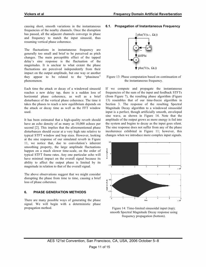
6.1. Propagation of Instantaneous Frequency
Figure 13: Phase computation based on continuation of the instantaneous frequency.
If we compute and propagate the instantaneous frequencies of the sum of the input and feedback STFTs (from Figure 7), the resulting phase algorithm (Figure 13) resembles that of our time-freeze algorithm in Section 3. The response of the resulting Spectral Magnitude Decay algorithm to a windowed sinusoidal input is a perfect, though artificially smooth, enveloped sine wave, as shown in Figure 14. Note that the amplitude of the output grows as more energy is fed into the system and begins to decay as the input goes silent. The sine response does not suffer from any of the phase incoherence exhibited in Figure 11; however, this changes when we introduce more complex input signals.
Figure 14: Time-limited sinusoidal input (top); smooth Spectral Magnitude Decay response using
frequency propagation (bottom).

Vickers et al Frequency Domain Artificial Reverberation
AES 121st Convention, San Francisco, CA, USA, 2006 October 5–8
Page 12 of 15
If we compute the instantaneous frequencies by taking phase differences between two frames that are one sample apart, as recommended in [16] and [22], the impulse response is the same as that of our time-freeze method; i.e., a decaying, N-periodic series of impulses, as shown in Figure 4. However, if we derive
!!
kby
subtracting the phases of frames R samples apart (instead of one sample apart), the impulse response is somewhat less regular, perhaps because the instantaneous frequency is only known modulo 2 ! [22].
Note that our basic Spectral Magnitude Decay algorithm, shown in Figure 7, automatically weights the influence of the phases of the input and feedback signals according to their respective magnitudes. As mentioned in [14] (in the context of phase locking), “In a sum of complex numbers, the summand with the greatest modulus naturally has the strongest effect on the phase of the sum.” Thus, this algorithm should satisfy the desired phase signal characteristics 5.1.2 and 5.1.3.
However, while the time-freeze reverb (Figure 3) has a pleasant quality, the Vega response [17] of our Spectral Magnitude Decay algorithm using instantaneous frequency propagation (Figures 7 and 13) can be somewhat ‘jittery,’ in violation of characteristic 5.1.5. This may be due to corruption of the instantaneous frequency information, because we are deriving a single frequency from the sum of the input and feedback signals in violation of the phase vocoder’s assumption of one partial per frequency channel.
Furthermore, as mentioned, the impulse response is extremely sparse and N-periodic, in violation of characteristic 5.1.1.
6.2. Phase Randomization
The resemblance of room responses to decaying white noise and the natural occurrence of phase randomization in reverberant environments suggest that we consider randomizing the phases.
The phases of each frequency channel k can be modified at each frame by adding a random offset [23]:
!k
stu
( ) = !ktu
( )+Vk ,u"k ,u
,
where
!k tu( ) is the instantaneous phase of the kth frequency
channel at time tu
,
!kstu
( ) is the instantaneous synthesis (output) phase of
the kth frequency channel at time tu
,
!k ,u
is a uniform random variable over [-π,π], and
Vk ,u ! 0,1[ ] .
Thus, when Vk ,u
= 0 for all frequency channels k and all
times tu
, no phase randomization is applied. If Vk ,u
= 1, the phase offsets will be completely random [23].
When the input to our Spectral Magnitude Decay algorithm is an impulse, unvoiced speech or other noise-like signals, phase randomization (or ‘phase dithering’) produces a high-quality response; many musical inputs also yield an acceptable output quality.
Unfortunately, with short STFT windows and pitched or sine-like input signals, phase randomization can produce a “whisperization” effect, because short Fourier transforms have a small number of channels with poor frequency resolution, and the randomized phases can’t help define the instantaneous frequencies [8]. On the other hand, long windows produce long latency times, which can be unacceptable for real-time applications.
In addition, full phase randomization does not allow frequency resolution finer than that of the FFT channel spacing, in violation of characteristic 5.1.2. As a result, we consider combining the instantaneous frequency propagation with partial phase randomization.
6.3. Partial Phase Randomization
By controlling Vk ,u
, we have a great deal of freedom regarding which channels undergo phase randomization, how frequently, and to what degree. As V
k ,u increases
from 0 to 1, the resulting random modulation disrupts the long-term periodicities, increasing the effective bandwidth of each sinusoidal component from a spectral line to a narrowband noise resembling the Fourier transform of the synthesis window [23]. (True reverberation may have a similar broadening effect on input spectral lines.)

Vickers et al Frequency Domain Artificial Reverberation
AES 121st Convention, San Francisco, CA, USA, 2006 October 5–8
Page 13 of 15
Ideally, we would like to preserve and reverberate the pitch information while adding a controlled amount of phase randomization. However, there may be an inherent conflict between requirements 5.1.1 and 5.1.2. To the extent we randomize the phases to diffuse the impulse response, the resulting frequency modulations may tend to blur the sub-bin frequency resolution. Since this presumably occurs in true reverberation as well, this may not be a problem so much as a control opportunity.
We can apply phase randomization either inside or after the feedback loop. Applying randomization inside the loop, as shown in Figure 15, may diffuse the impulse response more efficiently, using a smaller amount of randomization, than if we dither the phases outside the loop. However, adding randomization within the loop may permanently corrupt the sub-bin frequency information.
The optimal placement and depth of phase randomization, as well as which frequency bins it should be applied to and how often, remain subjects for further experimentation. For example, we may want to apply different amounts of phase randomization depending on whether a frequency channel is identified as being in the vicinity of a spectral peak. Also, we may want to apply more phase randomization to higher frequency channels, on the assumption that they don’t serve as coherent harmonics.
6.4. Intermittent Phase Disruption
Along the lines of what we found in Section 5.4 regarding the phase disruption observed when a note onset or offset reached a new delay tap, we might consider temporarily disrupting the phases from time to time, and then allowing phase coherence to resume. One way to do this would be to advance or retard the phases at irregular intervals, by simply scaling all the phases by an integer multiple as is done in integer time-scaling [8, 10]. The resulting temporal hickup would momentarily disrupt the phase coherence.
Figure 15: Spectral Magnitude Decay algorithm, including phase randomization, roomLevel( ! )
and dryMix.
7. RESULTS
7.1. Impulse Response
Given sufficient phase randomization, the impulse response of the Spectral Magnitude Decay algorithm is quite good and resembles decaying noise, with the desired frequency-dependent decay times and no unwanted coloration or metallic effects.
The perceived echo density can be quite high but (especially if the phase randomization is applied at the output) does not necessarily increase over time, unlike in real rooms and other reverb algorithms. Perceptually, the lack of increasing echo density does not appear to be a problem, since late reverb is generally defined to begin at the point where individual reflections become indistinguishable.

Vickers et al Frequency Domain Artificial Reverberation
AES 121st Convention, San Francisco, CA, USA, 2006 October 5–8
Page 14 of 15
7.2. Music Response
Given FFT sizes in the neighborhood of 8192 samples and moderate amounts of phase randomization, the Spectral Magnitude Decay reverb has a reasonably good quality output, though not good as that of convolution or the best time domain FDN reverbs. There can be a slight ‘echoey’ quality to the output, and if the FFT sizes are reduced, the algorithm begins to suffer from ‘whisperization.’
The parallel time-freeze method produces a higher quality output and, given limited phase randomization, is more tolerant of smaller FFT sizes. However, as mentioned previously, there are efficiency issues for longer decay times.
8. REMAINING PROBLEMS AND AREAS FOR FUTURE RESEARCH
We would like to further explore the following areas:
1. When, where, and how often should we apply what amounts of phase randomization?
2. Should we randomize the spectral magnitudes instead of (or in addition to) the phases?
3. How can we control the ‘modal density’ (average number of resonances per Hz) [2] to simulate the coloration of small, highly reflective rooms (e.g., bathrooms)?
4. What is the cause of the ‘echoey’ or ‘jittery’ quality sometimes exhibited by the Spectral Magnitude Decay reverb, and what is the best way to address this problem?
5. Can the Spectral Magnitude Decay reverb be modified to tolerate smaller FFT sizes, to reduce the latency?
6. How can the efficiency of the parallel time-freeze method be improved?
9. CONCLUSIONS
The Spectral Magnitude Decay method enables analysis-based synthesis of late reverberation, with easily controllable decay times as a function of frequency. If desired, multiple output channels could be generated using multiple inverse Fourier transforms with different phase randomization.
The Spectral Magnitude Decay method requires less memory than time domain Feedback Delay Networks, and it gives independent control over the reverb energy and decay time in each frequency channel. Unlike convolution reverbs, the current approach provides simple parametric control over the decay spectra, with a computational cost independent of decay time. This method could be especially promising for systems in which the audio has already been transformed into the frequency domain for other types of processing.
Errata or additional information on this topic may be provided at http://audioeffects.com/smd .
Some of the methods described in this paper may be the subject of a pending patent application.
10. REFERENCES
[1] W. Gardner, “Reverberation Algorithms,” in Applications of Digital Signal Processing to Audio and Acoustics, Kluwer Academic Publishers, Norwell, MA, 1998.
[2] J.-M. Jot and A. Chaigne, “Digital delay networks for designing artificial reverberators,” Proc. 90th Conv. Audio Eng. Soc. (preprint no. 3030), 1991.
[3] J. Laroche and M. Dolson, “Phase-Vocoder: About this phasiness business,” Proc. IEEE Workshop on Applications of Signal Processing to Audio and Acoustics, New Paltz, NY, 1997.
[4] J. Moorer, “About this reverberation business,” Computer Music Journal, 3(2):13-28, 1979.
[5] J. Flanagan and R. Golden, "Phase vocoder," Bell Syst. Tech. J., vol. 45, pp. 1493-1509, 1966 November.

Vickers et al Frequency Domain Artificial Reverberation
AES 121st Convention, San Francisco, CA, USA, 2006 October 5–8
Page 15 of 15
[6] D. Griffin and J. Lim, "Signal estimation from modified short-time fourier transform," IEEE Trans. Acoust., Speech, Signal Processing, vol. ASSP-32, no. 2, pp. 236--243, 1984 April.
[7] M. Dolson, “The phase vocoder: A tutorial,” Computer Music Journal, vol. 10, pp. 14-27, 1986.
[8] D. Arfib, F. Keiler, U. Zölzer, “Time-frequency Processing,” DAFX – Digital Audio Effects, John Wiley & Sons, Ltd., England, 2002.
[9] A. De Götzen, N. Bernardini, D. Arfib, “Traditional (?) Implementations of a Phase-Vocoder: The Tricks of the Trade,” Proceedings of the COST G-6 Conference on Digital Audio Effects (DAFX-00), Verona, Italy, 2000 December 7-9.
[10] J. Laroche and M. Dolson, “Improved Phase Vocoder Time-Scale Modification of Audio,” IEEE Transactions on Speech and Audio Processing, Vol. 7, No. 3, 1999 May.
[11] R. Schafer, The Tuning of the World: The Soundscape, Alfred A. Knopf, New York, 1977.
[12] Silophone web site, http://www.silophone.net/
[13] Infinity DSP Sample Looping Tools manual, Antares Audio Technologies, 2002.
[14] J. Laroche, “Time and pitch scale modification of audio signals,” in Applications of Digital Signal Processing to Audio and Acoustics, Kluwer Academic Publishers, Norwell, MA, 1998.
[15] M. Puckette, “Phase-locked Vocoder,” IEEE ASSP Conference on Applications of Signal Processing to Audio and Acoustics, Mohonk 1995.
[16] R. Sussman and J. Laroche, “Application of the Phase Vocoder to Pitch-Preserving Synchronization of an Audio Stream to an External Clock,” Proc. 1999 IEEE Workshop on Applications of Signal Processing to Audio and Acoustics, New Paltz, NY, 1999 October 17-20.
[17] S. Vega, “Tom’s Diner,” Solitude Standing, A&M Records, 1987.
[18] D. Dorran, E. Coyle, R. Lawlor, "An Efficient Phasiness Reduction Technique for Moderate Audio Time-Scale Modification,” Proceedings of the 7th International Conference on Digital Audio Effects (DAFx ’04), Naples, Italy, 2004 October 5-8.
[19] M. Schroeder, “New method of measuring reverberation time,” J. Acoust. Soc. Am., 37:409–412, 1965.
[20] E. Terhardt, “On the perception of periodic sound fluctuations (roughness),” Acoustica 30, 201-213, 1974.
[21] E. Terhardt, “Auditory roughness,” http://www.mmk.e-technik.tu-muenchen.de/persons/ter/top/roughness.html
[22] J. Brown and M. Puckette, “A high resolution fundamental frequency determination based on phase changes of the Fourier transform,” J. Acoust. Soc. Am., 94(2):662-667, 1993.
[23] M. Macon and M. Clements, “Sinusoidal Modeling and Modification of Unvoiced Speech,” IEEE Transactions on Speech and Audio Processing, pp. 557-560, 1997 November.