Embed Size (px)
Citation preview

Assessment of Mobile Location Technology
Final Report
23rd April 2010
Ofcom


271157 ICM TCS 1 01
19 February 2010
Assessment of Mobile Location Technology
Final Report
23rd April 2010
Ofcom
Mott MacDonald, Sea Containers House, 20 Upper Ground, London SE1 9LZ, United Kingdom
T +44(0) 20 7593 9700 F +44(0) 20 7928 2471 W www.mottmac.com
Riverside House, 2a Southwark Bridge Road, London, SE1 9HA


Assessment of Mobile Location Technology
Mott MacDonald, Sea Containers House, 20 Upper Ground, London SE1 9LZ, United Kingdom
T +44(0) 20 7593 9700 F +44(0) 20 7928 2471 W www.mottmac.com
Revision Date Originator Checker Approver Description
A 19/02/10 P Skeffington, S Vant,
A Whitelaw R Hewlett
B 31/03/10 P Skeffington,
A Whitelaw R Hewlett
C 22/04/10 P Skeffington A Whitelaw R Hewlett
Issue and revision record
This document is issued for the party which commissioned it
and for specific purposes connected with the above-captioned
project only. It should not be relied upon by any other party or
used for any other purpose.
We accept no responsibility for the consequences of this
document being relied upon by any other party, or being used
for any other purpose, or containing any error or omission
which is due to an error or omission in data supplied to us by
other parties
This document contains confidential information and proprietary
intellectual property. It should not be shown to other parties
without consent from us and from the party which
commissioned it.


271157/ICM/TCS/1/01 29 April 2010
Assessment of Mobile Location Technology
Chapter Title Page
Executive Summary i
1. Introduction 1
2. Industry structure and outline architecture for LBS 3
2.1 Industry structure ___________________________________________________________________ 3
2.2 High level architecture _______________________________________________________________ 4
2.3 Review of Positioning Technologies_____________________________________________________ 4
2.3.1 Outdoor positioning methods __________________________________________________________ 5
2.3.2 Indoor methods ____________________________________________________________________ 9
2.3.3 Elevation_________________________________________________________________________ 10
2.4 Wireless access ___________________________________________________________________ 10
2.4.1 Control plane approach _____________________________________________________________ 11
2.4.2 User plane approach _______________________________________________________________ 12
2.5 “Core” data and applications _________________________________________________________ 13
2.6 Niche Applications _________________________________________________________________ 14
2.7 Implications of the architecture for emergency services_____________________________________ 14
3. Emergency Services Requirement 17
3.1 Services Provided by the Call Handling Agents ___________________________________________ 17
3.1.1 The BT EISEC Service______________________________________________________________ 17
3.1.2 The Cable and Wireless Provided ALSEC Service ________________________________________ 21
3.2 Current Usage of the Call Handlers’ Services by Emergency Authorities________________________ 23
3.2.1 Interviews Undertaken ______________________________________________________________ 23
3.2.2 Take-up of Call Handler Services______________________________________________________ 23
3.2.3 Systems Architecture Employed_______________________________________________________ 25
3.2.4 Operational Usage and Benefits_______________________________________________________ 27
3.2.5 Perceived Shortfalls in Current Provision ________________________________________________ 29
3.3 Enhancement of the Provision ________________________________________________________ 29
3.3.1 Ongoing and Planned Enhancements __________________________________________________ 29
3.3.2 Requirements and Benefits __________________________________________________________ 29
3.3.3 Barriers to Enhancement of the Provided Services ________________________________________ 30
4. UK Mobile Operator Deployments 32
4.1 Current support for LBS _____________________________________________________________ 32
4.2 Future roadmaps for commercial location services ________________________________________ 32
4.2.1 Positioning techniques ______________________________________________________________ 33
4.2.2 Handset policies ___________________________________________________________________ 33
4.3 Other operator concerns_____________________________________________________________ 34
5. Mobile Technology and Market Trends 35
5.1 Trends in (commercial) mobile location services __________________________________________ 35
5.1.1 Key growth figures _________________________________________________________________ 35
5.1.2 GPS penetration___________________________________________________________________ 35
5.1.3 Smart phones _____________________________________________________________________ 36
Content
271157/ICM/TCS/1/01 29 April 2010
Assessment of Mobile Location Technology
5.1.4 Network sharing ___________________________________________________________________ 37
5.2 4G (LTE & WiMAX) ________________________________________________________________ 37
5.3 Femto cell________________________________________________________________________ 37
5.4 Satellite and location based services ___________________________________________________ 38
5.5 VoIP over mobile __________________________________________________________________ 40
5.6 Changes at device level _____________________________________________________________ 40
5.7 Location Based Applications _________________________________________________________ 40
6. Regulation and Standards 41
6.1 Current relevant regulation___________________________________________________________ 41
6.1.1 US regulation _____________________________________________________________________ 41
6.1.2 Anticipated changes to US regulations__________________________________________________ 42
6.1.3 Japanese regulations _______________________________________________________________ 43
6.1.4 Korean Regulations ________________________________________________________________ 43
6.1.5 EU directives _____________________________________________________________________ 44
6.1.6 Privacy issues ____________________________________________________________________ 44
6.2 Standards________________________________________________________________________ 45
6.3 Network related standards ___________________________________________________________ 45
6.3.1 GSM / UMTS / CDMA_______________________________________________________________ 45
6.3.2 WiMAX __________________________________________________________________________ 46
6.4 Other relevant standards ____________________________________________________________ 46
6.4.1 Mobile Location Protocol ____________________________________________________________ 46
6.4.2 CDMA Standards for location ________________________________________________________ 46
6.4.3 Timeline for emerging standards ______________________________________________________ 47
7. Analysis 48
7.1 Feasibility review __________________________________________________________________ 48
7.2 Option 1: Hybrid A-GPS with U-TDOA as fallback for 2G and 3G networks______________________ 49
7.2.1 Hybrid requiring A-GPS with UTDOA as fallback __________________________________________ 49
7.2.2 Estimated capital and operational costs _________________________________________________ 49
7.2.3 Benefits and drawbacks _____________________________________________________________ 50
7.3 Option 2: Hybrid A-GPS with OTDOA fallback for an LTE Network ____________________________ 50
7.3.1 Estimated capital and operational costs _________________________________________________ 51
7.3.2 Benefits and drawbacks _____________________________________________________________ 52
8. Recommendations 53
Appendices 54
Appendix A. USA ____________________________________________________________________________ 55
Appendix B. Japan ___________________________________________________________________________ 56
Appendix C. South Korea ______________________________________________________________________ 57
Appendix D. Summary of Positioning Technologies __________________________________________________ 58
Appendix E. Technology suppliers’ views__________________________________________________________ 60
Appendix F. Bibliography ______________________________________________________________________ 62
Appendix G. Glossary _________________________________________________________________________ 64
Appendix H. Supplier list_______________________________________________________________________ 68

271157/ICM/TCS/1/01 29 April 2010
i
Assessment of Mobile Location Technology
The purpose of this report is to address the five principal objectives set out by Ofcom in
their Invitation To Quote ref MC/021. These objectives are:
• To provide a technical description of the existing end to end architecture for the
delivery of location information to the emergency services;
• To provide an overview of technology that is currently available for providing
enhanced location information for mobile networks;
• To assess the likely market and technological developments during the course of
the next five years that will impact on the provision and quality of location
information;
• To compare the options and describe the relative advantages and disadvantages;
and
• To make recommendations for enhancing the accuracy and reliability of location
information.
The emergency services were consulted as part of this study in order to determine the
user requirement for location information for emergency calls that emanate from mobile
users. Whilst most organisations expressed a desire to obtain more accurate information
no metrics could be obtained to quantify the benefit. Further to this, it was identified that
the take-up of existing location based services was not universal. In the case of the BT
EISEC service, 74% of the 126 police, fire and ambulance organisations in the UK had
elected to use the information leaving 33 organisations that had not. From this it is
reasonable to conclude that the requirement for enhanced location information is not
universal, and is not currently a high priority for most organisations.
Our discussions with the mobile network operators have determined that the location
information that they currently provide is generally the longitude and latitude of the base
station and an estimate of the cell radius. In some instances timing advance was also
used to further refine the accuracy. Both the operators and the network equipment
providers indicated that the costs required to provide a significantly greater level of
accuracy were significant and would be of the order of £10’s of millions of pounds for the
capital costs alone.
Given that the requirement for enhanced location information does not have a high
priority within the emergency organisations consulted, and that the costs of implementing
a higher accuracy system would be high it has not been possible to demonstrate a clear
Executive Summary

271157/ICM/TCS/1/01 29 April 2010
ii
Assessment of Mobile Location Technology
cost-benefit justification for significantly modifying the existing regulatory arrangements.
It should be noted that both the USA and Japan justified their changes purely on public
safety and not on a direct cost-benefit case.
This situation should be reviewed at regular intervals, ie annually, in order to assess
whether the user requirement is increasing in priority and also to assess whether the
developing technologies are becoming sufficiently pervasive and affordable.
.

271157/ICM/TCS/1/01 29 April 2010
1
Assessment of Mobile Location Technology
Location based services can be used in four scenarios:
� Commercial
� Internal (use by operator for O&M, coverage etc)
� Emergency (999, 112)
� Lawful intercept [29]
This document is concerned with how emergency services can be supported by provision of better location
information. It does this by examining the needs of the emergency services and progress made in
commercial services, and in emergency services, largely in the USA, and how this may support emergency
services. In this study we are not concerned with internal use (by mobile operators) of location information.
Nor are we considering the requirements for lawful intercept.
In the UK an increasing proportion of emergency calls originate from mobile phones. This presents the
problem of locating the caller, particularly in cases where the caller may be incapacitated, confused, or in
unfamiliar territory and unable to tell the emergency services where they are.
Currently mobile operators in the UK are required to pass location information to emergency services, but
no constraints are placed on the accuracy of this location information. As a result, network based methods
are used which provide some guidance, but in some cases can be misleading.
In recent years there have been significant developments in mobile handsets and network positioning
technologies. These have been driven by a combination of regulation, particularly the FCC in the USA, and
also commercial development of Location Based Services (LBS) led by Japan and Korea. These
developments present an opportunity to improve the handset location information made available to the
emergency services. Given that these developments are continuing to advance, the question is when and
how to take up these opportunities to best effect.
In response to this situation, this project aims to:
� Understand how mobile technological developments may effect improvements in the quality of location
information provided via mobile networks
� Assess what technologies are available today and over the next 5 years
� Review what will be the features, accuracy and reliability of these technologies and what will be their
associated costs (opex and capex implications to mobile operators in particular)
� How will the operations of the emergency services be impacted by these developments
� Establish how other markets have tackled this problem
From the desk research and early interviews we quickly established that the USA was the key driving force
and still the most advanced in the area of mobile caller location accuracy, We carried out in depth
interviews with a number of players in the USA and collated and analysed data for Japan and Korea,
largely to understand if there were any significant differences in policy and implementation.
The structure of this report is as follows:
1. Introduction

271157/ICM/TCS/1/01 29 April 2010
2
Assessment of Mobile Location Technology
� Section 2 – Industry structure and outline architecture for LBS
� Section 3 – Emergency service requirements
� Section 4 – UK mobile operator deployments
� Section 5 – Mobile technology and market trends
� Section 6 – Regulation and standards
� Section 7 – Analysis and review of options, including cost aspects
� Section 8 – Recommendations

271157/ICM/TCS/1/01 29 April 2010
3
Assessment of Mobile Location Technology
The opportunity to provide good quality location information from mobile handsets has arisen partly from
the development of Location Based Services (LBS) which have grown very rapidly over the last 10 years.
This review therefore considers trends in the mobile and LBS market place and tries to determine how
these might support, or possibly constrain, the ability of operators to provide more accurate information.
2.1 Industry structure
The industry value chain in Figure 2.1 below categorises the types of players potentially involved in the
provision of mobile LBS.
Figure 2.1: Industry Value Chain for LBS
Satelliteoperator
Mobile operator
Mobile operator
Mobile operator
Mobile operator
Mobile operator
MVNO
Spatialinformation
bases
Routingnavigation
Geo-coding,Directory
Geo-content
Applications
Applications
Applications
Reseller
Devic
es/h
andse
ts
Source: MM created
Satellite operators add value by providing free to air signals1 which can be received by any receiver with
sufficient visibility and used to calculate an accurate position. Positioning data can also be provided through
a network based method by wireless operators. Increasingly, both techniques are used in a hybrid solution
to obtain better accuracy more reliably. Mobile network operators have adopted standards that support the
pass through of the location information to applications which support value add activities, for example
locating the nearest pizza bar.
Providing mobile LBS is a hugely complex task and in the early days was hampered by both a lack of
standards and a lack of equipment and systems supporting those standards. For example, a standard
format to enable exchange of geographic information between applications and networks using Geographic
Information Systems (GIS), such as exchange of billing information and billing models, was not available. A
range of “core” data and services encompassing GIS and billing are needed to enable a multitude of niche
applications to be integrated cost effectively into a complex end-end system. For instance GIS suppliers
have worked to standardise interfaces and common (or enabler) applications that are needed by many
niche applications. This has allowed mobile operators to support a wide range of application providers in a
relatively cost effective way. In many cases the device manufacturer may be selling the application (e.g.
iPhone applications of Apple). The enabling data and services may be provided by a wireless operator in a
_________________________
1 Note that paid for services will be available in Galileo that offer even greater location accuracy
2. Industry structure and outline architecture for LBS

271157/ICM/TCS/1/01 29 April 2010
4
Assessment of Mobile Location Technology
vertically integrated business model or as is currently the most common case by a 3rd
party service
provider.
In Figure 2.1 a wireless operator may provide the systems to support the “core” data and applications, but
this could equally well be done by a third party. Applications can similarly be provided independently,
providing customers with much more choice. In recognition of this Korea and Japan have introduced laws
to protect the privacy of individuals’ location information, both in real time and historically.
2.2 High level architecture
Location based services are considered using a conceptual outline architecture in four parts as shown in
Figure 2.2. Interoperability across the various domains is essential and getting this wrong can be costly and
time consuming and will make the difference between and successful and unsuccessful business.
Service interoperability requirements should be assured on all levels of the system architecture. The LBS
should be interoperable with several types of terminals (e.g., PDAs, GSM, 3G, LTE handsets) and
positioning infrastructures (e.g., indoor, GPS). The platform should be able to handle different coordinate
reference systems (e.g., WGS-84 and local systems) in order be able to utilize geographic data available in
existing GIS databases.
Figure 2.2: High level architecture of LBS
PositioningWireless access
“Core” dataand
applications
Nicheapplications
Source: MM Created
Sections 2.3 to 2.6 consider the evolution of the LBS from a technical perspective and how these
developments could support emergency positional information. The structure is based on Figure 2.2.
2.3 Review of Positioning Technologies
Ofcom has already commissioned a document that provides good detailed information on positioning
techniques, we have therefore provided summary information here [33]. Accuracies of the different
techniques can be highly variable according to scenario and circumstances. From a number of sources we
determined that the following range of location accuracies and Time To First Fix (TTFF) by positioning
technology is a good representation of the current status of these technologies.

271157/ICM/TCS/1/01 29 April 2010
5
Assessment of Mobile Location Technology
Figure 2.3: Overview of location performance assessment (approximate)
Location error (m)
Time from start up (s)
Cell ID200m
100m
10m
5m
5s0s 10s 15s 20s 25s 30s 60s
TDOA / AoA / EOTD
WiFi
Femtocell
A-GPS GPS
FutureA-GPS
In addition to accuracy and time to fix, a third important attribute of positioning technologies from an
emergency services perspective is the reliability with which the accuracy is specified, sometimes referred to
in the literature as yield. A high yield or reliability is a reflection of how often (statistically) an accurate
location can be achieved. This is becoming a more important factor for consideration as the FCC has
sought to enforce compliance. All positioning technologies have their strengths and weaknesses.
There are different combinations of positioning technology currently used for LBS:
� The network based, which takes advantage of the terrestrial networks to determine position
� The device based methods which take advantage of satellite (currently GPS) based technology
� Network based but with handset assist
� Handset based but with network assist
The calculations required to determine position whether by use of satellites or terrestrial networks are
intensive. Moving the calculations from the handset to the network supports minimising cost and complexity
of the handset.
2.3.1 Outdoor positioning methods
The selection of positioning techniques needs to be based on an optimum trade off between accuracy,
TTFF and reliability against the cost to implement. The impact on the mobile network operators’ capital and

271157/ICM/TCS/1/01 29 April 2010
6
Assessment of Mobile Location Technology
operational costs also needs to be considered because many of the solutions require substantial network
based implementation work and are thus expensive.
Handset based solutions tend to be easier but may incur the operator in extra costs due to the need to
encourage handset churn. A standalone GPS solution will give a longer time to first fix (TTFF) and is
therefore deemed unacceptable for emergency services.
2.3.1.1 Cell of Origin / Cell-ID
Many LBS applications establish the location of the user by simply identifying which base station (or sector)
the user is currently connected to – a technique known as Cell-ID. This basic form of location tracking is
supported by all GSM handsets.
The accuracy of this approach is generally commensurate with cell size or more specifically sector size,
though the use of directional antennas can increase location accuracy. The cell size varies with the
population density, being very small for dense urban areas and much larger for remote rural areas. The
smallest size may be between 200 metres and 1 kilometre whilst in the remote rural areas a cell may be
35-100 km (www.gsmworld.com). There can be occasional problems where a handset has been
associated with a neighbouring cell rather than the cell it is physically in.
Cell-ID can be handset based and hence require no extra network infrastructure and so is cheapest to
implement. Cell-ID can also be implemented as a network based solution.
This is often augmented with Timing Advance in the case of 2G networks and RTT in 3G networks to
reduce the positional uncertainty.
2.3.1.2 Round Trip Time (RTT)
This approach measures the start time between a downlink and its corresponding uplink, and compares
against a propagation model. This is network based with no handset changes required. It is standardised in
3GPP TS 25.215.
2.3.1.3 Uplink Time Difference of Arrival (U-TDOA)
This uses the time it takes for a signal to travel from the mobile device to the base station that it is
connected to and other nearby base stations. There is cost of location measurement units (LMUs). This
needs at least three monitoring base stations for 2D positioning and four for 3D. The base stations
measure the” time of arrival” of data from the handset, noting the time difference and combining it with
absolute time readings using GPS time provided by receivers also at the base stations.
U-TDOA supports legacy handsets; it is a network based approach requiring monitoring equipment to be
installed at virtually all of the base stations. For W-CDMA expensive time stamping needs to be
implemented. This is potentially the most expensive form of location technique for operators to implement.
2.3.1.4 Enhanced Observed Time Difference of Arrival (EOTD)
Devices with this capability measure the time difference between themselves and neighbouring
synchronized base stations, requiring the location of the base stations to be known. Accuracy to within 100
to 300 metres is achievable.

271157/ICM/TCS/1/01 29 April 2010
7
Assessment of Mobile Location Technology
This can be implemented as a handset based or a network based technique. Generally EOTD is
implemented as a handset based technique and is therefore less used than the TDOA method where the
calculation is done at the base station.
2.3.1.5 Angle of Arrival
This technique measures the phase differences at different parts of the antenna array in each base station
in order to determine the angle at which the signal arrived. The angles at which a signal arrives at two base
stations are thus triangulated to determine the location of the user. Accuracy may be affected in urban
areas due to multipath from reflections on buildings.
This technique needs only two base stations to determine position but requires expensive adaptive
antennas at base stations and is therefore very expensive for the network operators to implement.
2.3.1.6 GPS / GNSS
A more advanced and accurate location technology is GPS (Global Position System), which is generically a
Global Navigation Satellite System (GNSS) along with others including GLONASS and the emerging
European Galileo system. GPS satellites transmit time signals with associated almanac, ephemeris and
system health information. A receiver in a mobile device under “open sky” which can receive three or more
satellite signals can use the time signals to range the satellites and thus determine its own location. In this
way, a device equipped with a suitable chip can pinpoint its location to within 10 to 100 metres.
Limitations for standalone GPS are as follows:
� Time To First Fix (TTFF) – without assistance (see A-GPS), a receiver must locate its first satellite with
outdated almanac and ephemeris information and then update this directly from the low data rate GPS
signals to speed acquisition of the others. This can be a slow process taking over a minute.
� Though in L-Band, GPS signals are transmitted with comparatively low power from an altitude of about
20,000km and so their penetration of buildings is very limited.
� In urban areas, under trees or other cases of limited sky visibility, the positional accuracy can be limited
by multipath or visibility of only a small number of satellites.
Increasingly mobile handsets now come GPS positioning enabled. Until about 10 years ago issues of
antenna size and power consumption and battery capacity meant that it was very difficult to incorporate
GPS into user handsets. These issues have now been largely solved through chipset integration.
2.3.1.7 A-GPS
Assisted GPS (A-GPS) systems provide additional data to GPS equipped handsets through the network to
assist with the acquisition of satellites and the position calculations. When first introduced just over a
decade ago, largely in response to the US FCC 1996 regulation on emergency location, this service helped
to offset the considerable drain on handset processor power and battery. This essentially enabled
handsets to use GPS because processors and batteries were then major limitations.
Although these problems are much less significant now, the technique is still very valuable because it
provides for a much faster initial position, helps to offset problems of signal multipath and improves indoor
performance because the calculation can be done with only two satellites visible. The technique is still
effective in reducing power consumption, even though this is less of an issue now. For example SiRF’s

271157/ICM/TCS/1/01 29 April 2010
8
Assessment of Mobile Location Technology
newest chip uses 1% of the power of previous generations raising the prospect of continuous operation of
GPS handsets.
A-GPS provides the following benefits:
� Improve Time To First Fix (TTFF) – A-GPS uses the network to transmit updates to the satellite
ephemeris to tell the handset where to look for the satellites when it is switched on. The handset can
acquire this information from the satellite signals directly because these transmit both almanac and
ephemeris, but it takes time to assemble the whole ephemeris and so initially only the less accurate
almanac data are available. This means that the initial fix when the phone is switched on is outdated
and so acquisition and the initial position calculation take longer.
� Support to position calculations – Rather than have all the position calculations done at the handset, the
Assistance server can receive partial position information from the handset, complete the calculation
and send back the results.
� Correction information – In some cases, the cell tower can provide a differential correction which can
then be transmitted to the handset to improve the calculation accuracy, or used in the base station
position calculation which is then sent to the handset. Differential corrections compare the calculated
position to the surveyed location of the receiver and hence provide an empirical correction for transient
ionospheric conditions affecting accuracy.
The way that A-GPS works in a particular case is a function of both the chip in the handset and its
configuration and the operator’s policy and implementation.
For the purpose of this study, the interesting issues about A-GPS are as follows:
� It speeds up TTFF and improves accuracy
� It improves resistance to multipath and can increase indoor availability, but the extent of indoor
penetration and performance need to be clarified for a range of conditions
� The network traffic needed to operate A-GPS can be separated from voice traffic
� A-GPS can be implemented such that, by the time the call is put through to the call handling agent a
good position calculation has been achieved. In cases where the A-GPS server is performing the
calculation, it will have an accurate position for each handset within which it is interacting
� The use of A-GPS can incur data charges and it is often possible to disable it. Consequently some
owners may disable the system, particularly when roaming
� A-GPS may be hybridised with Cell-ID location because Cell-ID often works best in the dense urban
areas where A-GPS is poor
This is a network based but handset assisted technique. A-GPS can support 67% accuracy within 10 m in
“open sky” conditions.
2.3.1.8 Differential GPS
As mentioned under A-GPS, differential GPS provides a means to improve accuracy by comparing the
GPS position calculation with the receiver location, a precisely known location. The technique was initially
used to provide correction services for a range of applications in the period prior to 2000 when Selective
Availability, the intentional degradation of the GPS position, was withdrawn. At that time, the service was
provided by companies such as Racal Survey, who deployed about 80 reference receivers globally and
transmitted networked corrections via Inmarsat links. These services are still provided, and by networking

271157/ICM/TCS/1/01 29 April 2010
9
Assessment of Mobile Location Technology
the corrections from the reference stations, it is possible to achieve centimetric accuracy over large areas
for applications such as oil and gas extraction.
In addition to the commercial services, there have also been a number of public service implementations of
differential GPS. An early version of this was the transmission of corrections from individual reference
stations at marine beacons, the radio equivalents of lighthouses. These signals were used by groups such
as farmers to improve accuracies for precision farming.
More recently, a widespread differential service which is made freely available to the public has emerged
from the requirements of aviation users for an accuracy and integrity service. Generically these are known
as SBAS (Space Based Augmentation Systems). In Europe this is the EGNOS (European Geostationary
Navigation Overlay Service) system whose signals can provide correction so that up to 1.5 m accuracy can
be obtained. This again uses a network of reference station to provide area corrections which are then
relayed using Inmarsat and the Artemis data relay satellite.
EGNOS corrections, and the additional GPS like signals which are also transmitted directly from the two
Inmarsat satellites and Artemis, are used by a number of standalone GPS handheld receivers, such as
those produced by Garmin. Even if the use of EGNOS corrections in handsets is limited, it would certainly
be a possible alternative to providing local differential corrections directly from the base stations.
2.3.1.9 Skyhook
Skyhook’s XPS system (this is a particular company’s implementation) uses positioning data from WiFi
access points, Cell-ID and GPS satellites to obtain accurate position information. It was initially developed
to support the WiFi enabled iPhone and makes use of the SUPL standard. (It now supports applications on
Blackberry, Android and Mac OS X). As well as the algorithm and raw positioning data, it relies on an
accurate database of Cell-IDs and WiFi access points. This is done and re-done at intervals using drive
tests for which subscribers may also input data to the WiFi database. Skyhook’s accuracy compares well
with that of GPS and outperforms GPS on availability and speed (Table 2.1). As WiFi points in particular
may move from time to time the accuracy depends on the refresh rate, ie frequency of drive tests.
Table 2.1: Skyhook’s relative performance
XPS GPS A-GPS
Accuracy 10 meters 10 meters 30 meters
Availability 99.8% 80.0%t 95%
Time-To-First-Fix 1 sec 65 sec 30 sec
Source: http://www.skyhookwireless.com/howitworks/performance.php
2.3.2 Indoor methods
GPS is currently not suitable for indoors positioning, though it can work indoors when some sky visibility is
available, such as through a window. Even with A-GPS inputs however, it cannot be guaranteed to work
indoors. To overcome this, cell augmentation techniques can be used as part of a hybrid solution. For large
buildings, tower blocks, offices and shopping centres, this could be linked to the layout of the building, so
that a caller’s location may be mapped onto this. Some fire and rescue services in UK do have access to
building layouts [24].

271157/ICM/TCS/1/01 29 April 2010
10
Assessment of Mobile Location Technology
Nokia recently trialled an indoor positioning service [28] which uses WLAN in indoor environments to locate
the caller’s position.
There are techniques specifically developed for indoor areas and based on short distance signal
transmission [16] suitable specifically for location-based services in indoor environments like large
buildings, shopping centres, etc., where satellite and mobile network positioning methods are not so
effective or sufficiently precise. Local positioning methods include positioning methods where wireless local
area networks (WLAN), Bluetooth technology, Radio Frequency identification (RFID) or Infrared (IrDA)
technology (Active Badges etc.) are utilised. A number of systems/technologies have been proposed for
the underlying supporting platforms. An extensive survey of similar platforms can be found in [30].
2.3.3 Elevation
None of the positioning systems gives a good indication of elevation. GPS is currently accurate to 100-
200m in altitude. In the future Galileo will improve this to 10-20m accuracy levels. Some larger buildings in
the USA are being fitted with beacon networks (in ceilings in order to be able to determine on which floor
an emergency caller is).
2.4 Wireless access
Wireless standards are complex and not necessarily globally interoperable. GSM (a TDMA based
approach) was widely deployed in Europe, whilst CDMA was deployed in North America and Asia but these
two were not interoperable. For 3G networks, W-CDMA (in Europe) is not interoperable with FOMA (in
Japan). For 4G both WiMAX and LTE are both global standards, but implementations are expected to vary
in spectrum and modulation techniques etc.
The different positioning methods deliver positioning information in differing formats. To get information
about the position of the handset to the location based applications requires the information to transit from
the handset, across the terrestrial wireless network into the core network and then to the applications. The
wireless network may need to support several or any one of the positioning methods. Converters, known as
gateways are provided to translate and re-format the information appropriately. Over the last 10 years
much effort has gone into standardising interfaces and the development of gateways.
Each wireless standard requires a specific implementation of these gateways as illustrated in Figure 2.4.
Note: All of these standards can operate in more than one spectrum band, and the availability of multi-band
phones will determine the extent to which roamers from overseas can access UK networks and hence
emergency services. It is assumed that a user whose handset does not support the local spectrum bands,
is aware that they have no mobile service whatsoever and hence will not be able to use the handset for
emergency calls. (This is very different from the case where a user has a phone that supports the
appropriate bands but is pre-paid and out of credit or is out of coverage of his/her own mobile operator’s
network).
In wireless access networks there are two ways of collect and forward the positioning data:
� control plane
� user plane (also referred to as SUPL)

271157/ICM/TCS/1/01 29 April 2010
11
Assessment of Mobile Location Technology
The control plane is voice centric, and has the advantage that it can be used by users with no data
subscription. The user plane is an IP based approach whereby the handset directly invokes services with
trusted location applications. This effectively uses a standard bearer channel and needs minimal interaction
with the mobile operator’s (private) signalling network, and so is easier to implement.
2.4.1 Control plane approach
The control plane approach is reliable, secure, is voice centric and supports legacy terminals (e.g. 2G). It
can be deployed to users who do not necessarily have a data services subscription with their operator.
This, however, can require signalling system ie SS7 upgrades. Modification of the control plane (ie
signalling network elements and protocols) is a costly and complex business for the mobile operator. To
implement this involves the use of gateways between the wireless access network, the core mobile
operators systems and the applications.
Figure 2.4: Example of control plane use in various wireless networks for LBS
Mobile Network (GSM)
MobileNetwork (W-CDMA)
MobileNetwork (CDMA)
SMLC
SAS
GMLC
MLP
MPC
Mobile operatorBilling systems
Mobile operatorauthentication
MPP
MLP
Mobile operatorBilling systems
Mobile operatorauthentication
MLP
Source: MM Created
The function of the SMLC (Serving Mobile Location Centre) is to schedule and co-ordinate resources to
determine the position of the handset. The GMLC (Gateway Mobile Location Centre) controls delivery of
the position data, user authorisation, billing and other functions.
From Figure 2.4 above it is clear that whilst the use of the SMLC/GMLC provides a solution which is simple
in concept. What is less clear from the diagram is that its implementation has considerable expense and
complexity. This due to the number of interfaces which need to be developed, integrated and tested. A
mobile operator may have a mix of technologies, eg GSM and UMTS 3G/W-CDMA in Europe, some North
American operators have CDMA and GSM, necessitating the purchase of more than one gateway type,
and so this upgrade becomes a multi-system, multi-vendor integration problem, which will be slow and
expensive. The standards are complete for both the GSM and the W-CDMA cases. However each vendor

271157/ICM/TCS/1/01 29 April 2010
12
Assessment of Mobile Location Technology
always has freedom to implement the standards with or without optional features. As most mobile operators
choose more than one vendor in the network layer, there will always be some additional development or
potentially upgrades prior to integration of say a GMLC. See standards section for details of location
protocols which must be supported.
Once installed the SMLC/GMLC can support a number of positioning methods, for example, Cell-ID, Cell-
ID/RTT, A-GPS,CGI/TA, E-CGI, and CGI. Typically each type of positioning would have different software
and this would need to be enabled and paid for by the operator.
2.4.2 User plane approach
The user plane approach was developed to minimise the interaction with signalling networks. It therefore
obviates the need for all of the location systems to be integrated into the various wireless technologies and
hence reduces the scope of the operator’s integration problem. The handset communicates directly with
the SUPL server and must support SUPL, hence legacy handsets are not supported, and user must have a
data services subscription.
The Open Mobile Alliance (OMA) was created to bring open standards, platform independence and global
interoperability to LBS. The SUPL standard acknowledges A-GPS as the most accurate positioning
techniques available today and uses this, enabling lower power consumption and enhancing the sensitivity
of GPS receivers. This standard also allows new business models where an applications provider can use
the location based information provided directly from the handset to its location based server, without the
involvement of the mobile operator (except use of a standard bearer to carry the information).
The Open Mobile Alliance has defined a Mobile Location Based Architecture which is currently at v1.2.
Within this architecture interfaces are defined to support roamers. Support for roamers in mobile networks
abroad is complex, and to enable support for identifying the location of a roamer is similarly complex. This
supports both commercial and emergency location reporting and enables operators to offer users an opt-
out for commercial LBS whilst maintaining a default opt-in for emergency service location. Figure 2.5 below
indicates a number of interfaces defined within the OMA to support LBS for roamers.
Figure 2.5: OMA support for location based services for Roamers
MLSClient
(handset)
Requesting location server
Homelocation server
Visitedlocation server
Location PrivacyChecker
Privacy Checking Protocol
Le Lr Lr
Roaming Location Protocol
RLP RLP
LidLpp
Source: Open Mobile Alliance
271157/ICM/TCS/1/01 29 April 2010
13
Assessment of Mobile Location Technology
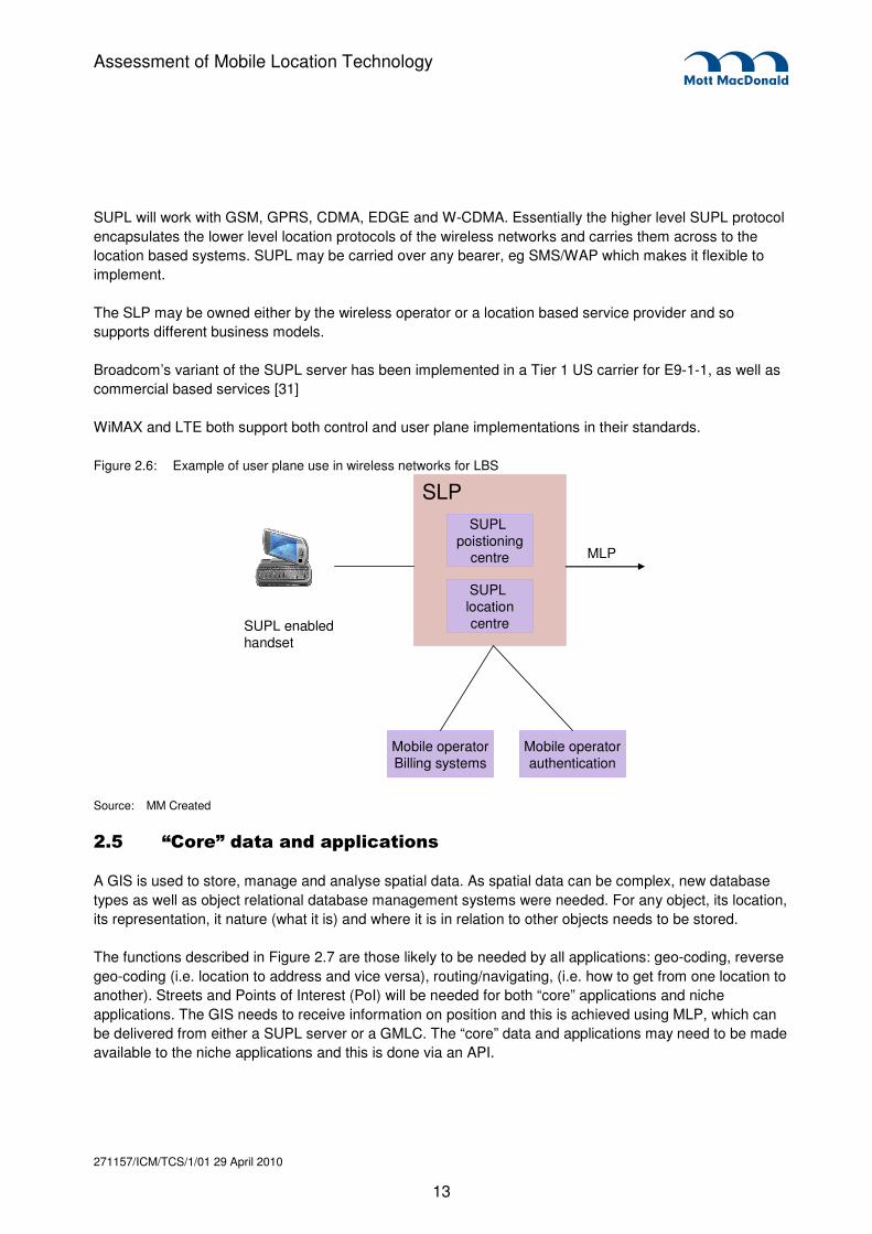
SUPL will work with GSM, GPRS, CDMA, EDGE and W-CDMA. Essentially the higher level SUPL protocol
encapsulates the lower level location protocols of the wireless networks and carries them across to the
location based systems. SUPL may be carried over any bearer, eg SMS/WAP which makes it flexible to
implement.
The SLP may be owned either by the wireless operator or a location based service provider and so
supports different business models.
Broadcom’s variant of the SUPL server has been implemented in a Tier 1 US carrier for E9-1-1, as well as
commercial based services [31]
WiMAX and LTE both support both control and user plane implementations in their standards.
Figure 2.6: Example of user plane use in wireless networks for LBS
Mobile operatorBilling systems
Mobile operatorauthentication
SUPL locationcentre
SUPL poistioning
centre
SLP
SUPL enabledhandset
MLP
Source: MM Created
2.5 “Core” data and applications
A GIS is used to store, manage and analyse spatial data. As spatial data can be complex, new database
types as well as object relational database management systems were needed. For any object, its location,
its representation, it nature (what it is) and where it is in relation to other objects needs to be stored.
The functions described in Figure 2.7 are those likely to be needed by all applications: geo-coding, reverse
geo-coding (i.e. location to address and vice versa), routing/navigating, (i.e. how to get from one location to
another). Streets and Points of Interest (PoI) will be needed for both “core” applications and niche
applications. The GIS needs to receive information on position and this is achieved using MLP, which can
be delivered from either a SUPL server or a GMLC. The “core” data and applications may need to be made
available to the niche applications and this is done via an API.

271157/ICM/TCS/1/01 29 April 2010
14
Assessment of Mobile Location Technology
Figure 2.7: GIS and other “core” applications
MLP
GMLC or MPC
Spatialdatabasegateway
PoI, streets, dynamic content
Geo-coding,proximity,
routing
API
SUPLserver
2.6 Niche Applications
Figure 2.8 shows the application architecture for niche applications, this must support authorisation, opt-in
and billing for the application and may be different from that offered by the mobile operator, ie. Not related
to network usage, but to the value of the information.
Figure 2.8: Niche applications for mobile location based services
API
Coreapplications
Content&
applications
PoI, streets, dynamic content
Billing, authentication, authorisation,
discovery
http://www.scangis.org/scangis2003/papers/27.pdf
2.7 Implications of the architecture for emergency services
The architectures which have emerged suggest different approaches to supply the emergency services
with location information. We outline three approaches for consideration.
� A minimal change architecture
� A GIS with automapping of location information for every Emergency Authority/PSAP
� A single GIS shared amongst services and possibly geographic regions
Minimal change
This architecture assume that the additional location accuracy is provided but with minimal changes to any
of the emergency services. This is the lowest investment case, performs the minimum function of getting
the information to the PSAP in the required timescales.

271157/ICM/TCS/1/01 29 April 2010
15
Assessment of Mobile Location Technology
Figure 2.9 illustrates this approach; the current interface would be adapted to provide the additional fields
required to convey confidence measures etc.
This would be the quickest and arguably the cheapest approach, however, it does not support more flexible
organisation structure within the emergency services, nor would it contribute to any cross services
collaboration, or back-up.
Figure 2.9: Minimal change approach
Mobile OperatorMobile
Operator
FixedOperator
FixedOperator
CAACAA
PSAP
Locationdatabase
Static directory of names, phone numbers, addresses
Dynamic location of mobiles ….
Voice
Location related data
ISDN Lines
ISDN or FR
Call to firstresponder
PSAPPSAP
Source: MM Created
We assume that the operator provides the increased accuracy information in the same format.
Ensure all PSAPs use a GIS
Figure 2.10 illustrates the same case as Figure 2.9 but by ensuring that each PSAP has a GIS. The
location information is automatically mapped to the GIS. An ability to send turn-by-turn navigation to first
responders ensures that there is less scope for misinterpreting the confidence levels of the location data
and could speed the response of the emergency services. Each PSAP has its own GIS and navigation
application. This requires standardisation of GIS to ensure that all PSAPs (or at least neighbouring ones
and cross services PSAPs in the same geography can interoperate in case of a disaster). If in the future
PSAPs need to hold building layouts of large building complexes, these too should be standardised.

271157/ICM/TCS/1/01 29 April 2010
16
Assessment of Mobile Location Technology
Figure 2.10: All PSAPs use a GIS
Mobile OperatorMobile
Operator
FixedOperator
FixedOperator
CHACHA
PSAPcall centre
LocationdatabaseLocationdatabase
ASP
PSAPcontroller
GIS
Call to firstresponder
Location related dataASP
ISDN Lines
ISDN or FR or Ethernet
Source: MM Created
Centralised GIS
Location information is “pushed” to the GIS, so that all PSAPs share access to one system (web access).
They can then all “pull” the same location information. PSAPs have their own turn-turn navigation
application. There is potential for savings by having a single GIS for all services. Note that application
service providers could provide location information.
Figure 2.11: Centralised shared GIS
Mobile OperatorMobile
Operator
FixedOperator
FixedOperator
CHACHA
PSAPcall centre
LocationdatabaseLocationdatabase
ASP
PSAPcontroller
GIS
Call to firstresponder
Voice
Location related dataApplication
Service Provider
Shared GIS
ISDN Lines
ISDN or FR or Ethernet
Ethernet
Source: MM Created

271157/ICM/TCS/1/01 29 April 2010
17
Assessment of Mobile Location Technology
3.1 Services Provided by the Call Handling Agents
Under General Condition 4 of the operator’s license, the network operator has an obligation to provide
access to the emergency numbers (999 and 112) and to provide location information for the callers. In
order to fulfil this obligation, the network operators contract with a Call Handling Agent (CHA) to provide
Emergency Call Handling Functions. Although there are four call handling agents in the UK, the majority of
calls to the emergency numbers (112 or 999) in the UK are handled by BT and C&W.
As part of this project we have reviewed provision by BT and C&W.
In addition to being able to make the Calling Line Identity (CLI) and associated location information
available verbally, the two 999 Call Handling Agents have implemented technology such that they make
this information available on a server which can be queried by emergency services’ control room systems.
In the case of calls from mobile telephones as well as from landlines, information about the location of the
caller is made available in this way.
3.1.1 The BT EISEC Service
BT handles the emergency calls from mobile telephones for Vodafone, Orange, O2, 3G UK Ltd, Mapesbury
and T-Mobile (for Telematics calls only). BT provide the EISEC service to the Emergency Authorities which
enables the electronic transfer of the callers CLI to the Emergency Authorities, and allows access to an
EISEC-DB in order that the Emergency Authority can obtain address information relating to the origin of
emergency calls. The EISEC service is available to emergency authorities receiving calls using
appropriately configured primary or basic rate ISDN lines. BT publishes a Suppliers’ Information Note (SIN
278) to provide information about the EISEC service including detail of requirements for interfacing
between an emergency authority’s control room equipment and the EISEC-DB.
3. Emergency Services Requirement

271157/ICM/TCS/1/01 29 April 2010
18
Assessment of Mobile Location Technology
An overview of the call handling process and use of the BT EISEC service is illustrated in Figure 3.1:below.
Figure 3.2: Overview of BT call handling service
Source: MM created
As illustrated above, the call from the mobile subscriber is initially routed to the BT call handling operator.
At this point the caller is asked which service they require and the BT operator accesses the ESDB system
to determine the correct Emergency Authority based on the caller’s request and the basic zone information
obtained from the mobile operator via the call signalling. BT state that they onward connect 60% of
emergency calls received.
The service to the Emergency Authority is delivered in 2 phases :
• Phase 1 is delivery of the call with basic CLI and zone information included as part of the signalling
of the ISDN call; and
• Phase 2 is the ability for the Emergency Authority to Access the BT EISEC database to collect the
relevant caller and location information.
Retrieval of information from the mobile network operator
The BT EISEC database is populated by data received from the relevant mobile network operator at the
time of a 999/112 call. The information relating to a specific 999/112 call is available to Emergency
Authorities via the EISEC interface for approximately thirty minutes after the call is made, however the call
taker can request the information verbally from the operator within an hour, even if the Emergency
Authority is not an EISEC user.

271157/ICM/TCS/1/01 29 April 2010
19
Assessment of Mobile Location Technology
The information provision by the mobile operators is the same for all networks and follows a standard
(ETSI) format. Two documents define this interface between the MLO Location server and the BT EISEC
DB. NICC Specification ND1013:2002/11 is based on the interface defined by the Location Inter-operability
Forum (LIF). It identifies sections within the LIF TS 101 v3.0.0 specification, clarifies which options are
applicable to a UK emergency location information service and details an optional PNO-ISC MLP extension
- "Emergency Location Information Interface". In addition, ETSI “TS 102 164 V2.0.0 (2006-xx) -
Telecommunications and Internet converged Services and Protocols for Advanced Networking (TISPAN);
Emergency Location Protocols” endorses and defines a profile of the OMA specification OMA-TS-MLP-
V3_2-20051124-C that are applicable to the emergency location information services.
There are no noticeable differences between mobile operators in terms of speed of availability of the
location information – although there may be differences in whether the location reported is from the time of
the original call or from the time the lookup is performed. BT also stated that all the mobile operators
reliably provide the required location information. BT could not comment on the accuracy, although they did
undertake a study some years ago that came to the conclusion that the average cell radius returned was in
the region of 2 Km and felt that the maximum cell radius was likely to be about 30 Km.
Obtaining the Location information from the EISEC database server
As stated above, once a call has been forwarded by the BT Operator to an Emergency Authority, the
Authority can access the BT EISEC database during a period of thirty minutes to obtain the relevant caller
information.
The EISEC Client uses the TCP/IP protocol to provide reliable transport, and for an Emergency Authority
system to access the EISEC Client it must first initiate a successful TCP/IP connection. Following this the
transactions between the Emergency Authority and the BT EISEC Server use a set of defined Protocol
Data Units (PDU).
Following successful logon to the EISEC client gateway, the Emergency Authority can access the location
query data that has been transferred automatically to the EISEC-DB access area of the client machines as
the 999/112 call is processed by the BT Operator. Thus Emergency Authorities only have access to data
for customers who have made a recent 999/112 call, with this data persisting for a period of only 30
minutes.
Service levels
There are no specific service levels in place for the EISEC service provision although there is the
Emergency Services Code of Practice which specifies that BT, as a Call handling agent, must answer 95%
of 999/112 calls within 5 seconds.
As the emergency services contract with BT wholesale for provision of their services, there is also an
applicable contract schedule (225) however these do not really contain detailed service levels. The
overriding requirement is compliance with General Condition 4 supported by the ETSI standard for
obtaining the information from the mobile operators.
BT do however try to minimise failures by providing redundancy in the form of providing more than one
EISEC Client system location gateway for the Emergency Authorities to use. An Emergency Authority can
thus increase resiliency by simultaneously connecting to one or more EISEC client, although a second
connection to the same EISEC client gateway will cause the termination of the first connection.

271157/ICM/TCS/1/01 29 April 2010
20
Assessment of Mobile Location Technology
BT also seek to maximise availability of the data by recommending that the mobile operators have two
servers, which most do. This differs from mandated provisions in the United States.
Support for greater levels of location accuracy
BT’s work to enhance the EISEC service to allow location information to be passed for emergency calls
from mobile phones started more than 7 years ago. The enhancement that was introduced in September
2003 and SIN 278 was up-issued to version 1.3 to support this. The actual protocol remained largely
unchanged from previous versions except that a query for a mobile phone call could return location
information.
The specification contains fields within the prescribed PDU message structures so that future enhancement
of the location information being provided can be supported. These include altitude, speed, direction and
address fields. The inclusion of these should encourage the emergency service system providers to future
proof their developments in light of information that may be made available in the future, however
improvements in accuracy are dependent on information coming from the mobile operators and to date
those improvements have not happened.
BT has considered other options for enhancement of the accuracy of the provided location information
independent of the mobile operators. Consideration was given to a smart phone application that would
follow the telematics approach to give location information by data to accompany an emergency call. BT
also trialled an LMU (Location Measuring Unit) system placing a unit on every 3rd mast site within a trial
area. These gathered information on mobiles within range so that a better location fix could be calculated
using a method similar to eOTD. This was technically successful but was not progressed as, although the
cost of each unit was very cheap, rolling out across the UK mast sites would require considerable
investment.
Changes that would be required to support greater location accuracy
Although there are already extra fields described in the BT information for their EISEC service, it would still
be necessary to enhance the interface in a limited way to prescribe a second query should be undertaken
after a short delay if, for example, the mobile operators could provide an improved second fix of a mobile’s
location at the slightly later time. The emergency services would have to perform a similar enhancement to
their control room systems to support this enhancement.
In addition the interfaces are currently based on older technologies (PDUs over TCP/IP) and although it is
not required, a move to an XML based platform in the future could be desirable.
BT also commented that even support for VoIP or SMS would not necessarily entail changes to their
EISEC service as these are already being supported to some degree at the moment. The key challenge to
providing greater location accuracy is getting the information from the network operators.
It was noted that delivery of calls over ISDN is required. Although there is no date for retirement of ISDN as
yet, the effect of the rollout of the next generation network from BT may make ISDN obsolete in the longer
term.

271157/ICM/TCS/1/01 29 April 2010
21
Assessment of Mobile Location Technology
3.1.2 The Cable and Wireless Provided ALSEC Service
Cable and Wireless provide the emergency call handling for T-Mobile, which includes the following who all
use T-mobile’s network services:
� Virgin Media
� CPW
� Opal Telecom
� Matrix and
� IKEA
An overview of the call handling process and use of the Cable and Wireless ALSEC service is illustrated in Figure 3.3:
below:
Figure 3.4: Overview of the Cable and Wireless Call Handling Service
Source: MM created
As illustrated above, callers who dial 999 or 112 from a network which has elected to use Cable and
Wireless as the emergency call handler, are initially routed through to Operators at one of the Cable &
Wireless call centres. The Operator routes the call to the most appropriate local emergency authority based
on questioning the caller about which service they require (Fire, Police, Ambulance or Coastguard) and the
location of the caller.
Cable and Wireless have also implemented a ‘Silent Call’ Solution which enables the accidental calls,
which are particularly prolific from mobile phones, to be screened out at the initial stage. If the Cable and
Wireless Operator cannot make any voice contact with the caller the call is extended to “silent call” solution
which allows the caller to press 5 on the keypad if they are unable to speak, if 5 is not pressed the call is
271157/ICM/TCS/1/01 29 April 2010
22
Assessment of Mobile Location Technology
released. For calls where there is uncertainty after verbal questioning the caller is passed to the relevant
Police control room.
The ALSEC service enables the information concerning the subscriber address details for fixed line calls or
the approximate location of a mobile caller to be made available to the appropriate Emergency Authority on
a secure website. The information is only available for current emergency calls and if location information is
required retrospectively after a period of about an hour following the call, the emergency authority must
apply following the Regulation of Investigatory Powers Act 2000 (RIPA) guidelines.
For Emergency Authorities that do not subscribe to the ALSEC service, subscriber address details for fixed
line calls or the approximate location of a mobile caller can nevertheless be passed verbally when the call
is being forwarded through.
Obtaining the Location information from the ALSEC location server
As shown above access to the ALSEC Web server is only available through secure government
organisation networks. The ALSEC location server is password protected and emergency Authorities are
each provided a username and password when their ALSEC service is provisioned.
In order to facilitate the lookup of the location details via the provided XML interface, the caller’s number
(CLI) is initially passed as additional digits appended to the signalling for the call forwarded to the
Emergency Authority. These digits can be extracted, passed to the call handling system and used for
subsequent queries of the ALSEC location server. If the call has been made from a mobile telephone the
Emergency Authority would expect to obtain the approximate location of the mobile telephone handset
itself at the time of the request. This would take the form of a coordinate position and details for an ellipse
together with a confidence level to describe the assessed certainty that the caller is located within the
described ellipse.
Service levels
Cable and Wireless commented that although there is not any formal SLA associated with the provision of
location information, for about 90% of calls the location information arrives before connection of the call on
to the emergency service is complete. A 3s delay is what is expected, but C&W felt this to be a worst case
rather than a best case.
In order to protect the availability of the live system and to facilitate development of interfaces to the
ALSEC system Cable and Wireless provides a test environment that can be accessed via the Public
internet. Cable and Wireless also deliver the ALSEC solution as a dual redundant architecture to enhance
availability and reliability.
The accuracy of data in the location database is crucial. A number of regular checks are carried out as
routines.
� Daily reports check that cell and post codes are sent correctly to the emergency services.
� Weekly reports capture cells where no post-code information is captured, liaison with T-mobile rectifies
this.
� If calls are routed incorrectly (ie not to right geographic emergency service) there is a process to correct
this.

271157/ICM/TCS/1/01 29 April 2010
23
Assessment of Mobile Location Technology
Impact of changes in location accuracy levels
Cable and Wireless felt that the ALSEC system would be able to support changes in the shape of cells or
the confidence levels that could be associated with improvements in accuracy. If the cell referencing
information is changed however this would necessitate changes to the system.
Other services supported
SMS
Cable and Wireless have implemented support for emergency notification by SMS. Users must pre-register
and can then send a text to “999” service. The text is routed to BT onto a text to talk server. This is then
routed as a call to the emergency services.
When subscribing to the service users are provided terms and conditions and guidance on how to send
emergency SMS texts. The automatic location service from T-Mobile can be used in this instance to
support locating the mobile.
3.2 Current Usage of the Call Handlers’ Services by Emergency Authorities
3.2.1 Interviews Undertaken
During the study attempts were made to obtain feedback and opinions from Police, Fire, Ambulance and
Coastguard users. As a result, information and comment was received which is encapsulated in this
section. Participation from the Ambulance service was sought via multiple routes, however feedback
received indicated the pressure of work was a barrier to involvement.
3.2.2 Take-up of Call Handler Services
Take-up of the enhanced location information services from the call handling agents is still not universal
despite the low barriers to its use. Those Emergency Authorities which have adopted the technology are
listed in Figure 3.5 and Figure 3.6Error! Reference source not found., below.

271157/ICM/TCS/1/01 29 April 2010
24
Assessment of Mobile Location Technology
:
Figure 3.5: Emergency Authority Take up of BT EISEC service as at September 2009
Police Fire Ambulance
Cambridgeshire, Central
Scotland, Cheshire, Cleveland,
Cumbria, Derbyshire, Devon &
Cornwall, Dorset, Dumfries &
Galloway, Durham, Essex, Fife
Grampian, Greater Manchester,
Gwent, Hampshire, Hertfordshire,
Humberside, Kent, Lancashire,
Lincolnshire, Lothian & Borders
Merseyside, Metropolitan,
Norfolk, North Wales, North
Yorkshire, Northamptonshire,
Northern, Northern Ireland,
Nottinghamshire, South
Yorkshire, South Wales,
Staffordshire, Strathclyde,
Suffolk, Surrey, Sussex, Thames
Valley, Tayside, Warwickshire,
West Mercia, West Midlands,
West Yorkshire, Wiltshire
Total – 45 of 52
Avon, Buckinghamshire,
Cheshire, Cleveland, Cornwall,
Cumbria, Devon, Dorset,
Dumfries & Galloway, Durham,
Essex, Grampian, Hampshire,
Hertfordshire, Kent, London,
Lothian & Borders, Merseyside,
Mid & West Wales, Norfolk,
North Wales, North Yorkshire,
Northern Ireland, South Wales,
Staffordshire, Strathclyde,
Suffolk, Surrey, Tayside,
Warwickshire, West Midlands,
West Sussex, West Yorkshire
Total – 33 of 58
East of England, East Midlands,
Great Western, Isle of Wight,
London, Northern Ireland, North
East, North West, Scottish, South
Central, South East Coast,
South West, Staffordshire, Welsh,
West Midlands, Yorkshire
Total – 15 of 16

271157/ICM/TCS/1/01 29 April 2010
25
Assessment of Mobile Location Technology
Figure 3.6: Emergency Authority Take up of Cable and Wireless ALSEC Service as at September 2009
Police Fire Ambulance
Central Scotland, Cheshire,
Derbyshire, Dorset, Durham,
Greater Manchester, Hampshire,
Hertfordshire, Humberside
Lancashire, Merseyside,
Northamptonshire,
Nottinghamshire, Norfolk,
Northern, South Wales,
Staffordshire, Suffolk, Sussex,
Yorkshire, West Midlands
Total – 21 of 52
Cleveland, West Midlands
Total – 2 of 58
Berkshire, Cheshire & Mersey,
Cumbria, East Anglia, East
Midlands, East of England, Great
Western, Greater Manchester,
Hampshire, Lancashire, London,
North East, Oxford, Two Shires,
Welsh, West Midlands,
Yorkshire
(No total is provided as some
Pre-2006 and some Post-2006
Trust area names used.)
3.2.3 Systems Architecture Employed
An interface can be developed for the Emergency Authority call handling system to extract the details and display the information to the operator. Figure 3.7 below illustrates a typical control room layout and information flows.
Figure 3.7: Emergency Services Use of Call Handlers’ location services for Emergency calls

271157/ICM/TCS/1/01 29 April 2010
26
Assessment of Mobile Location Technology
Source: MM created
The above figure illustrates how the location information is obtained from the call handler’s server in
parallel with the ongoing emergency call. The Operator then verifies the automatically obtained caller
information and ensures that the caller and incident locations entered in the Command and Control system
are 100% correct. Some Emergency authorities that subscribe to the automated services only display the
information on the Integrated Communications and Control System (ICCS) operator screen and from there
on entry into the Command and Control (C&C) and GIS systems reverts to a manual entry. In other
Emergency Authorities information is fed automatically into the incident pages in the command and control
system and even into the GIS system. Error! Reference source not found. below shows how the
Emergency Authorities interviewed for this study have developed their main control room systems to
enable the information obtained from the EISEC and/or ALSEC services to be distributed amongst them.

271157/ICM/TCS/1/01 29 April 2010
27
Assessment of Mobile Location Technology
Figure 3.8: Population of control room systems with automatic location data
Service EISEC
?
ALSEC ? Population of
ICCS
Population of
C&C
Population of
GIS
Dyfed Powys Police � � N/A N/A N/A
Metropolitan Police � Planned Automatic Automatic Automatic
West Midlands Police � � Automatic Automatic Automatic
Northamptonshire
Police � � Automatic Automatic Automatic
Greater Manchester
Police � � Automatic Automatic Automatic
Gwent Police � � N/A N/A N/A
Hampshire Fire and
Rescue Service � � Automatic Automatic Automatic
Communities and Local
Government (CLG),
FiReControl Project
� � Automatic Automatic Automatic
Welsh Assembly
Government (Fire) � � Automatic Automatic Manual
Fife Fire and Rescue
Service � � N/A N/A N/A
London Fire Brigade � � Automatic Manual Manual
Maritime and
Coastguard Agency � � Automatic Manual Manual
During our discussions, BT has noted that the way emergency services display the information differs –
there are examples of good practice such as London Ambulance which plot the information on their GIS for
display to their control room operators including the radius of the area but others just display the centre
spot, which is potentially misleading as it may be perceived as implying a level of accuracy which does not
exist.
3.2.4 Operational Usage and Benefits
The location lookup currently results in a cell coverage area being retrieved from the mobile operator. It is
not a triangulated reference to the caller location but rather a map reference for the centre of the coverage
area of the cell. The cell coverage may of course be elliptical or conical in shape so this would be
analogous to the centre of gravity of the defined area. One network (Vodafone) does use Timing Advance

271157/ICM/TCS/1/01 29 April 2010
28
Assessment of Mobile Location Technology
to improve the accuracy of location for users of 2G base sites – the effect of this is to reduce the radius of
the defined area.2
Emergency Authorities reported that they found the information indicated areas with radii of a kilometre or
so in most instances and, although this is not sufficiently accurate to locate a caller with any accuracy, they
felt it was useful as a start point for operators especially when there was little else to go on.
Key drivers for the emergency services are ensuring optimal speed of response and speed of attendance
at the scene of an incident, as well as efficient management of resources.
Accurate information regarding caller location may mean that the call taker can dispatch a resource to the
correct place with optimal speed ensuring that whenever possible victims receive care within the critical first
hour following an incident. This is known as the ‘Golden Hour’ as a victim’s chances are greatly diminished
if emergency care is not delivered within that time.
Despite the limitations in the case of mobile callers, the enhanced location information can be useful to
control rooms to assist in locating the caller and potentially reduce call handling times, especially in cases
where the caller is in unfamiliar surroundings and may just know a road name, eg. ‘High Street’ for
example. In addition, if the location information is used to pre-populate field within the incident page of the
command and control system keying of information can be avoided which again contributes to reduced call
handling times. Where authorities also have integrated mapping systems then further value can be
achieved by passing the location information directly to the mapping system when the call is received. A
marker can then be displayed on the control room operator’s screen on a street map to assist with the
caller dialogue.
Location information is also used to support call challenge initiatives and screen for hoax calls, for example
where a fire in London is reported by a caller whose location is obtained as being somewhere in
Manchester. Hoax calling is a significant problem, reported in particular by Fire Services, and so
intelligence about the actual location of a caller can prove an effective aid in services’ efforts to effectively
manage their resources.
Although the accuracy levels could be improved, the current accuracy would nevertheless be suitable for
use for Pre-alerts. This is where a resource initially mobilised to the general area of the incident whilst the
specific location is being ascertained from the caller.
The Emergency Service code of Practice contains targets for answering calls to the emergency numbers,
as follows :
� the Call handling agents (eg BT, C&W etc) must answer 95% of 999/112 calls within 5 seconds.
� the Police Service aims to answer 999/112 calls within 10 seconds;
� the Ambulance Service is to answer 95% within 5 seconds; and
� the Fire and Rescue Service and Coastguard aim to answer 95% within 10 seconds
Fire services and Police Forces stated they had additional local targets which relate to times for attendance
at the scene of the incident, for example. Emergency Authorities who subscribed to the EISEC and/or
ALSEC services felt they played a significant part in allowing them to meet these targets, given the
_________________________
2 See BT SIN278

271157/ICM/TCS/1/01 29 April 2010
29
Assessment of Mobile Location Technology
propensity for these services to enable a reduction in call handling times and thus contribute to faster
mobilisation of resources to an incident scene.
3.2.5 Perceived Shortfalls in Current Provision
The current provision does not provide levels of accuracy that can be relied upon to actually locate a caller.
The current provision is used more for informing the dialogue between the Emergency control room
operator and the caller, rather than providing information to actually pinpoint an incident for dispatch of
resources. BT stated that they have, however, not received many complaints from the emergency services
themselves about the accuracy of the information provided. This may be in part due to good
communication with Emergency Authorities which correctly sets their expectations for the service.
Using the information supplied by EISEC or ALSEC at present, callers cannot be located within large
buildings such as shopping centres and office blocks with the Emergency Authority operator being reliant of
the caller being sufficiently familiar with their surroundings to provide details of their location.
One particular shortfall is that location information is not made available for mobile users who are roaming.
This is a particular concern as subscribers from overseas may struggle to describe where they are if they
require emergency assistance as they are likely to be in unfamiliar surroundings and may have problems
expressing themselves in English too.
BT feel that one of the biggest improvements for emergency services call handling and response would be
to provide better location information however not all PSAPs have taken up the EISEC system even though
it has been available (for fixed lines) since 1998 and evidence has demonstrated it can improve call
handling times by between 30 seconds and 2 minutes. Barriers to take up should be low as BT does not
charge for the information and control room system suppliers widely have the necessary modifications in
place as they have implemented at other customers.
3.3 Enhancement of the Provision
3.3.1 Ongoing and Planned Enhancements
3.3.1.1 Support for 999 for VoIP users
From 8 September 2008 revisions to General Condition 4 came into force which mean that VoIP providers
who enable their users to make calls to the PSTN must provide the ability to make "999" and "112"
emergency calls. The network operator must also provide Caller Location Information for calls to the
emergency call numbers where the VoIP service is being used at a predominantly fixed location.
3.3.2 Requirements and Benefits
3.3.2.1 Other types of information required by emergency services
Emergency Authorities expressed a requirement for GPS equivalent accuracy for every mobile caller’s
location. The Metropolitan Police stated that this was because there are some calls such as abandoned
calls that are extremely time critical.

271157/ICM/TCS/1/01 29 April 2010
30
Assessment of Mobile Location Technology
Emergency Authorities also indicated that being able to locate a casualty within a large building would be
very useful. Although the Fire Services do collect risk data for buildings under their obligations as part of
Fire Services Statute 2004 section 7, part 2, paragraph D for high risk premises, these are not in a pre-
determined common format that can be used with a system of co-ordinates. These building plans are
however often shared amongst the first responders.
Increased regionalisation of the services means that previous dependence on local knowledge of the
control room staff can no longer be guaranteed. This means that the staff answering the emergency calls
will increasingly need electronic location information to assist them when locating an incident or caller.
In the future the emergency services may require live video, PowerPoint or similar graphic displays
accessible via mobile devices as well as in fixed locations eg PSAPs.
Some Emergency Authorities felt they could C&C and control forms and GIS displays. Some Fire Service
respondents also noted it would be useful to populate their GIS with the location of callers awaiting answer
rather than on answer as this would pick up trends and help to identify high volumes of calls relating to a
single incident. This would mean control room staff could possibly prioritise other single calls outside of the
area which are unlikely to relate to the same incident.
Emergency Authorities are increasingly employing data terminals within mobile resources and location
information for the caller and incident could additionally be automatically sent for display on these devices.
Greater Manchester Police and Northamptonshire police both made comment concerning how useful
location information for calls on non-emergency lines as well as 999/112 calls would be.
3.3.3 Barriers to Enhancement of the Provided Services
3.3.3.1 Barriers to enhancement by Service Providers
Overwhelmingly service providers cite the slow and, in some areas, limited take-up of the EISEC and
ALSEC services as reasons why further investment to provide improved information could not be justified.
Some of the suppliers (ie operators) have stated that getting the attention of emergency services can be
difficult. This is due to the fact that responsibility is split over several government departments. Some
suppliers had concerns about whether the training to PSAP personnel was effective, a balance needs to be
achieved between keeping communications simple whilst ensuring that they are effective.3
VoIP Issues
During our interview, Cable and Wireless noted that getting location information from corporate users of
VoIP is likely to become an increasing problem and although solutions exist, organisations are not motivate
to invest in these areas unless compelled to do so.
Cable and Wireless described a solution they had investigated for location of VoIP callers which was from a
North American company called ConneXon. In this solution two servers are used in redundant
configuration, to interrogate the location of routers, switches etc on an organisation’s private IP network.
_________________________
3 See reference xxx which shows the BT training collateral provided for cell-ID based location
271157/ICM/TCS/1/01 29 April 2010
31
Assessment of Mobile Location Technology
The IP address of each device returns a null string or a string containing the location information if it has
been defined. The IP-PBX is data-filled to direct 999 “invites” (ie call set-up equivalents) to the server,
where it is attached to pre-set CLIs. A normal PSTN call is generated with the pre-set CLIs. This is then
handed over to C&W or BT in the normal way. The pre-set CLIs have an address location associated with
them.
Although a technically feasible solution the cost remains a barrier to take-up of this and similar technologies
in the UK. In North America, there is a health and safety obligation which compels the use of such
solutions, but in UK there is not. Implementation would be expensive for end user organisations and there
is no margin for the operators to resell the system. Although possible, remote hosting of servers to provide
facilities to multiple customers is expected to be infeasible due to the anticipated security and privacy
concerns of businesses. However, in essence, the problem with providing location information for VoIP
callers on private IP networks mirrors the problem that has existed for some time for many corporate
organisations where outbound calls provide the CLI of the main switchboard rather than the individual
caller. These exceptions are currently dealt with by operators who obtain verbal information from the callers
as to the location of the incident. It is likely that the volume of such calls will increase as the take-up of VoIP
increases.
3.3.3.2 Barriers to enhancement by Emergency Authorities
It is important to remember that the location being obtained is not actually that of the suspected incident but
rather the location of the caller reporting that incident. This will necessarily reduce opportunities for
automation of the onward transmission of the information between the systems used to track and mobilise
resources as there will always be a requirement for operator intervention and the inherent manual
processes to obtain the location of the actual incident.
Fire and rescue services in England comment that they were unwilling to invest any further money in the
Command and control systems whilst they are preparing to transfer to the nine new FiReControl Regional
Control Centres (RCC). After transfer to RCC, FRS’s legacy control room equipment will become
redundant and any investment now, in the run up to the transfer, is seen as nugatory.
When asked why EISEC and/or ALSEC services were not used, emergency authorities routinely replied
that this was because resources had been prioritised elsewhere to more ‘front line’ tasks. Whilst the
services are meeting their call handling targets using the technologies and intelligence from the caller that
is currently used it is unlikely that services will invest time or money to upgrade systems and modify
processes to take advantage of better information or even make better use of the information already
available.

271157/ICM/TCS/1/01 29 April 2010
32
Assessment of Mobile Location Technology
4.1 Current support for LBS
During our interviews with mobile operators we gathered various information about the state of their
networks and their plans in respect of LBS. Table 4.1 provides an overview of the current status of LBS
offerings by UK mobile network operators.
Table 4.1: Summary of current features supporting LBS in UK mobile networks
Feature Vodafone O2 T-Mobile 3
GPS handset penetration4 %
GSM(2G) Cell-ID + Cell-ID TA
Cell-ID & Cell-ID + TA5
Cell-ID & Cell-ID + TA6
n/a
3G none Cell-ID
LTE none none none Long term plan but no LBS
planned
WiFi none none none
Femto cells none none none none
Dongles/netbooks n/a7 n/a n/a
Indoor X X X
Elevation/Height solution X X X
GMLC in network (2G) √ √ √
A-GPS support off
International roamers No CLI No CLI No CLI No CLI
National (ie LSS roamers) No CLI No CLI No CLI n/a
GIS X X X
Source: interviews with key UK personnel
4.2 Future roadmaps for commercial location services
All mobile operators consulted viewed the LBS market as low growth, none expected that this would be a
key engine for growth and were not anticipating investing in this area.
Table 4.2: Summary of future features supporting LBS in UK mobile networks
Feature Vodafone O2 T-Mobile 3
3G Cell-ID feasible (not installed)
Cell_ID
LTE none none none none
WiFi none none none
Femto cells 2 none No rollout plan No open plan
_________________________
4 Figures were obtained but as these are confidential are not included un the report.
5 For O2 the timing advance feature is not permanently switched on, and takes 15 minutes to switch on
6 The timing advance functionality is only available across the parts of the network implemented using Ericsson equipment
7 No emergency service is currently available from these devices
4. UK Mobile Operator Deployments

271157/ICM/TCS/1/01 29 April 2010
33
Assessment of Mobile Location Technology
Feature Vodafone O2 T-Mobile 3
scenarios for Femto cells
Source: interviews with key UK personnel
Note that emergency service requirements currently only apply to voice services, and most voice is still
carried over 2G networks in the UK.
The mobile operators were not anticipating investing in LBS services, some saw the likes of Google as
much more effective at providing these solutions and favoured a handset based approach using user plane
(SUPL), with little need for the mobile operator to get involved. The TTFF provided by SUPL is deemed
sufficient for commercial applications, however our best practice studies indicated that SUPL was not
currently favoured for emergency services.
In general no operators wished to be forced to provide greater accuracy for 3G services, due to the need to
invest large sums of money. The general preference was to invest in LTE.
4.2.1 Positioning techniques
Currently only limited positioning technologies are installed by the UK mobile networks. It was generally
agreed that a GPS solution would be required to meet the FCC’s accuracy levels.
A-GPS is fully standardised (for 3GPP) but in practice has not been implemented, this would require costly
changes in all mobile UK operator networks.
Control plane implementations would be more costly and more reliable, however, user plane
implementations would be cheaper.
Of the operators considering the roll-out of Femto cells, two scenarios were being considered
� User determined location, address provided on registration and the user must remember to update if
they move the Femto cell
� Ability of Femto cell to “sniff” its location, using radio, IP or via correlation with post-code (if a converged
product is provided ie broadband and Femto cell provided by the same service provider).
The provisioning of location information for 2G was generally available using Cell-ID, however for 3G this is
lacking in the UK. Some operators have not yet made the decision to roll-out LTE and do not anticipate
providing LBS functionality with this, unless compelled to do so. It should be noted that 3 has no 2G
network and that currently a request for greater accuracy of location that required network based
positioning would put them at a disadvantage.
4.2.2 Handset policies
None of the operators we spoke to had any policy to speed the adoption of GPS devices. If a GPS or A-
GPS solution is mandated then the mobile operators see a number of issues with this:
� GPS handset penetration is currently low, being restricted to high end devices
� Average handset replacement cycle is about 3 years in the UK, so we should anticipate at least 5-6
years to move the whole user base to GPS handsets.
� Additional handset cost could reduce ability to use service for lowest end most price sensitive
customers

271157/ICM/TCS/1/01 29 April 2010
34
Assessment of Mobile Location Technology
� Mobile operators can not compel users to choose a GPS handset, nor even compel them to upgrade
their handset
� GPS chips even though power requirements have fallen may still drain the battery actually reducing the
possibility that end user can make any emergency call at all.
MVNOs would also need to be consulted if a handset based approach were necessary (Carphone
Warehouse, Tesco, Virgin etc.) as these organisations influence choice of handset.
4.3 Other operator concerns
Mobile operators were reluctant to disclose the costs of LBS, two operators indicated that anticipated
capital spend was in the low millions (ie 7 figure sum). This was not inconsistent with the cost estimates we
obtained talking to suppliers. Operational costs might be expected to vary depending on the business
model (ie the amount of design and support which is outsourced rather than insourced, and whether the
design effort is capitalised or appears as increased operational cost over the contract period). A figure of
opex £300-450 k pa was suggested in one case.

271157/ICM/TCS/1/01 29 April 2010
35
Assessment of Mobile Location Technology
This section examines the evolution of mobile technologies, the mobile market and how these might
accommodate the location options examined in the previous section.
The following trends suggest that whilst GPS handsets are becoming more available, they still represent
relatively low numbers of the total mobile user base. For the foreseeable future, emergency location
information provided using network based in 2G, networks will have to remain an important part of the
location mix.
Femto cells are very low in numbers at present, though with high growth rates offer the potential to support
positioning indoors more easily. In the USA these are offered with an extended aerial for basement
coverage. It is possible that the FCC will (eventually) group Femto cells as edge devices rather than mobile
devices, so that different standards and positioning techniques will apply. Femto cells in the USA come pre-
fitted with a GPS receiver (not the case in UK)
The deployment of LTE with its smaller cell sizes may make cell based positioning more accurate in urban
areas but in rural areas the commercial pressures will still dictate that the cells are maximum size.
5.1 Trends in (commercial) mobile location services
Worldwide many of the mobile operators already have Location Based Services (LBS) infrastructure.
Initially it was thought that LBS would be mostly for consumers. Bigger more colourful displays support
consumers using handsets as navigation devices. In terms of mapping applications, O2 has Telmap,
whereas Vodafone has Wayfinder. The iPhone supports Co-pilot and many other geo-location applications.
There are now emerging business requirements, many of which are associated with management of field
workforces, asset tracking, fleet management etc. Our discussions with various organisations appear to
characterise the LBS market as a series of niche markets, with each application appealing to a specific
niche. This may explain the problems that the mobile operators in the UK face. Their direct sales approach
is much more suited to mass market than niche market. Some of them have partnered with LBS application
providers, but non are reporting high volumes of traffic and revenue.
5.1.1 Key growth figures
ABI research predicts that LBS will grow by 156% from $1.7 billion in 2008 to $2.6 billion in 2009, and to
$14 billion in 2014. Gartner is in broad agreement with these figures, claiming $12.7 billion by 2013.
Annual. LBS revenues in the USA alone are projected to reach $3.5 billion by 2013 (Frost & Sullivan) [12].
Some high-revenue services such as navigation, fleet management, friend/family finder, mobile social
networking and local search require higher accuracy whilst others require less accuracy. For higher
accuracy GPS solutions are required, whereas lower accuracy (cheaper) solutions are sufficient in other
scenarios.
5.1.2 GPS penetration
GPS penetration across Europe is currently low. (For example, many of Nokia’s current handset models
support GPS but it will be a few years before full mass penetration is achieved). For LBS to proliferate
requires GPS handsets as demonstrated in the Japanese and Korean markets:
5. Mobile Technology and Market Trends

271157/ICM/TCS/1/01 29 April 2010
36
Assessment of Mobile Location Technology
� Japanese customers of NTT Docomo can use location based services in Japan and will be able to use
the same service abroad (based on Motorola MALS, which enables overseas roaming via SUPL, but
also allows the use of GMLC based, low latency, high availability location, this is an A-GPS system).
NTT Docomo has launched its “ i-concier” service which uses location based information to target users
with a range of services. MALS allows this to be extended to its roaming customers. NTT Docomo treats
security of its users’ personal data with a high priority.
� In Japan and Korea widespread use of GPS has preceded changes to the emergency services mobile
location requirement. A larger revenue share to service providers in Japan and Korea encouraged
competition in the location based services LBS area.
Application stores such as Apple’s iPhone and (to a much lesser extent) Google’s Android will support the
drive for a wholesale mobile market, which encourages application and content providers to proliferate.
Alternative positioning technologies such as WiFi and Cell-ID allow 3rd
party application developers access
to low accuracy positioning information at low cost. Google maps, Nokia Maps and Android offer this
information for free. The result is that chip manufacturers are integrating A-GPS and Skyhook (WiFi) onto a
single chip. This will inevitably increase the take-up of location based services [10].
Market research [21] predicts that GPS phones will account for 37% of all shipments (535 million) by 2012.
The number of users of mobile location services accessed via GPS phones is also expected to grow
strongly. The report predicts that by 2012 the worldwide user base of the most popular location-enabled
services, navigation and mobile social networking, will reach 150 and 127 million respectively. This is still
rather low if we look at the following numbers for worldwide mobile use (by technology).
Table 5.2: Penetration of mobile use worldwide
Mobile standard Number of users worldwide (millions)
Q2 2009
GSM 3,450
W-CDMA 255
W-CDMA HSPA 133
CDMA200 300
CDMA EV-DO 118
CDMA EV-DO rev A 12
Source: GSM Association
GPS is also more likely to be used in safety applications such as the avoidance of pedestrian and vehicular
collisions [22], such as the one trialled by Nissan and Docomo in early 2009. GPS is now available in GSM
& 3G handsets, but it should be noted that the increase in WiFi, LTE and WiMAX may lead to a
requirement for this functionality in more devices.
5.1.3 Smart phones
The increasing uptake of smart phones is likely to result in more phones with both 3G, WiFi and GPS on a
single device. This will force suppliers to support LBS across a range of wireless technologies. IDC Dec
2008 projected smart phone growth of 24% against overall handheld growth of 8%.

271157/ICM/TCS/1/01 29 April 2010
37
Assessment of Mobile Location Technology
� Vodafone has announced a deal with TeleAtlas to enable LBS for routing and mapping applications for
Vodafone subscribers around the world. This will amongst other things support its key new M2M
programme. This is part of the Vodafone strategy to increase its share of the market globally by
providing this service across other mobile networks [7].
� Orange has procured systems and software (with Signalsoft) to enhance its LBS capabilities [8][9].
5.1.4 Network sharing
Network sharing is expected to continue, with operators seeking to share costs wherever new cell sites are
required and perhaps to put some cell sites out of service. The sharing of LBS infrastructure is a possibility
and would keep costs at a minimum for the mobile operators. There is also the possibility that a managed
service is provided by another party. This will support driving down both capex and opex for the mobile
operators. This could free up both funds and more importantly management expertise in the mobile
operators to focus on higher value add solutions such as LBS.
5.2 4G (LTE & WiMAX)
Most mobile operators have announced plans to roll-out 4G and in some cases trials have started. It should
be anticipated that 4G will happen in the next 5 year period. Indeed, Informa expects a handful of cautious
early forays from the likes of Verizon and NTT Docomo towards the end of the year (2010).
It has been anticipated that LTE commercial launches in GSM-only markets could slip back to 2013-2014
as HSPA+ comes into the market.
There have so far not been mass deployments of LTE networks, and whilst some WiMAX networks have
started to rollout in the UK, these are not mass deployments. LTE rollouts have begun in Japan and the
USA and are starting in Europe.
For example O2 carried out trials in December 2009 of LTE in Slough, O2 was chosen by parent company
Telefonica to be one of six different providers in six countries (Spain, UK, Germany, Czech Republic, Brazil
and Argentina) to take part in trials of its 'up to' 340Mbps next generation Long Term Evolution ( LTE )
based Mobile Broadband technology.
The case for early LTE in the USA is being driven by end-user demand for enriched quality of experience
and new market opportunities (M2M, rural zone, M-advertising, and the availability of 700MHz spectrum).
LTE devices are available with both user (SUPL) and control plane location, for business application (e.g.
Fleet tracking) [18].
The 4G standards are not yet complete, but 4G standard-setters agree that 4G location information will
have to be accurate to within tens of metres and work seamlessly across dense urban, urban, suburban,
rural, and indoor environments. This will be necessary to meet the future demands of extremely content-
rich LBS and other applications as well as mobile navigation [15].
5.3 Femto cell
Femto cell use in the USA is already advanced, whilst within the UK mobile operators are expected to
increase, their deployment, driven in part by the mobile operators’ needs to make better use of spectrum.

271157/ICM/TCS/1/01 29 April 2010
38
Assessment of Mobile Location Technology
� Femto cells are smaller and hence the same spectrum can be re-used at more frequent geographical
intervals (smaller cell sizes).
� Smart phones use 8 times the signalling power of a laptop and with the increased penetration of smart
phones mobile operators might be expected to offload the traffic at soonest point onto a fixed network
(i.e. DSL line in homes/office).
Demand is expected to be driven up also due to poor in-home coverage of the mobile networks Figure 5.1
shows the predicted growth of Femto cells.
Vodafone had a trial launch in June 2009 and this has been stepped up with a more high profile marketing
launch 19th January 2010 (Sure Signal), which coincided with the launch of Vodafone’s iPhone product
(Smart phone).
Figure 5.1: Global UMTS femtocell shipments, 2008-2011
Source: iDATE
5.4 Satellite and location based services
Back in 1999, the European Union decided to set up a global satellite navigation system (GNSS), known as
Galileo, for civil and commercial use. In early 2010 the European Commission awarded the contracts for
Galileo’s first satellites, launchers and support services. In 2011 the European system will finalize its
validation phase. As a result, the initial service provision of Europe’s satellite navigation system could start
as early as 2014. Changes are in process to accept Assisted-GNSS-GP as a 3GPP standard. The chips
required in handsets will be slightly different to those GPS chips already being integrated into UMTS
handsets, this may slow the adoption of this technology by the mobile operators. In Japan QZSS will
support enhanced GPS, this will enable better coverage in built up areas and in mountainous areas, where
GPS performance is not so good.
GPS
The US Department of Transportation; Global Positioning System (GPS) Civil Monitoring Performance
Monitoring Specification; DOT-VNTSC-FAA-09-08; April 30, 2009.gives the locational accuracies as
follows:
For Single-Frequency C/A-Code on L1 (1575.42 MHz):

271157/ICM/TCS/1/01 29 April 2010
39
Assessment of Mobile Location Technology
� 7.8 m for 95% of the time Global Average URE (user range error) during Normal Operations over all
ages of data.
� This improves to 6.0 m 95% of the time Global Average URE during Normal Operations (at Zero AOD)
taking only most recent data into account.
� 12.8 m for 95% of the time Global Average URE during Normal Operations at Any AOD
These average out at about 10m.
The above figures refer to the basic L1 code signal. Current GPS satellite updates have also started to
transmit a second open service signal on 1227.6 MHz which is known as L2. The L2 signal is stronger
than the L1 allowing for lower power consumption in reception and easier integration into smaller mobile
devices. Using L2 should bring the accuracy down towards 5m, particularly if both frequencies are used
and compared to reduce ionospheric effects. Beyond this, GPS III will add an L5 frequency which should
provide additional accuracy gain as well as better indoor performance. This is a safety of life signal for
civilian use which is 3dB more powerful than L1 and L2 and is on 1176.45 MHz. The progression from L1
to L1/L2 and eventually L1/L2/L5 will lead to much improved accuracy and reliability, particularly when
Galileo improvements are also adopted in parallel,
Galileo
At present there are only two Galileo test satellites in orbit. As the constellation builds however, satellite
positioning services will be much improved over today’s GPS service, not least because the open services
from both systems are compatible. A contract was recently placed for the construction of the first 14 full
operational Galileo satellites for launch between 2012 ad 2014. The following services will be available.
� The Open Service (OS) will be free for anyone to access. The OS signals will be broadcast in two
bands, at 1164–1214 MHz and at 1563–1591 MHz. Receivers will achieve an accuracy of <4 m
horizontally and <8 m vertically if they use both OS bands. Receivers that use only a single band will still
achieve <15 m horizontally and <35 m vertically, comparable to what the civilian GPS C/A service
provides today. It is expected that most future mass market receivers, such as automotive navigation
systems, will process both the GPS C/A and the Galileo OS signals, for maximum coverage.
� The encrypted Commercial Service (CS) will be available for a fee and will offer an accuracy of better
than 1 m. The CS can also be complemented by ground stations to bring the accuracy down to less
than 10 cm. This signal will be broadcast in three frequency bands, the two used for the OS signals, as
well as at 1260–1300 MHz.
� The encrypted Public Regulated Service (PRS) and Safety of Life Service (SoL) will both provide an
accuracy comparable to the Open Service. Their main aim is robustness against jamming and the
reliable detection of problems within 10 seconds. They will be targeted at security authorities (police,
military, etc.) and safety-critical transport applications (air-traffic control, automated aircraft landing,
etc.), respectively.
The Galileo Supervisory Authority has funded the Gawain project to develop a combined GPS / Galileo /
UMTS receiver. It is not clear how advanced this is and whether or not it has been taken up by any
commercial providers.. Work on commercially available dual system receivers is already well underway
and, for example, U-Blox for example have already developed a commercial GNSS chip which is ‘Galileo
ready’,
Assisted-Galileo is in the process of consideration in the 3GPP standards and is likely to be very similar in
implementation to the GPS equivalent.

271157/ICM/TCS/1/01 29 April 2010
40
Assessment of Mobile Location Technology
5.5 VoIP over mobile
VoIP is expected to become ever more popular and due to the inherent location independence of the
application, the problem of position determination will become more pressing. An IETF standards
framework and some normative work has already started for fixed VoIP, but it is unclear how this will apply
to mobile VoIP. It will be necessary to estimate future VoIP growth and consider the impact. Some
countries, from a regulatory and emergency services perspective, have drawn a distinction between VoIP
which originates on a PSTN and VoIP which is basically computer to computer and treatment can be
defined differently for each scenario.
LTE will only support voice over IP.
5.6 Changes at device level
Informa forecasts that volume sales of smart phones are to grow by 33.5% year on year in 2009 and by
36% in 2010 to account for 27% of the total number of handsets sold in 2010.
Global Sales of GPS GSM/W-CDMA handsets were 28m in 2007, 78m in 2008 and are predicted to reach
770m in 2014 [25].
Smart phones, with their ability to download applications and access content more easily, will drive LBS.
Test facilities already exist to allow the testing of UMTS A-GPS devices [17].
5.7 Location Based Applications
Signalsoft
This company provides a solution which supports E9-1-1 as well as commercial based services:
Openwave
This company supports basic LBS using Cell-ID and advanced LBS making use of A-GPS. Both make use
of mobile location protocol (MLP). It supports position determination across a range of cellular technologies
such as CDMA, GSM/UMTS, iDEN, WiMAX, and Long Term Evolution (LTE) [11].
TeleAtlas
TeleAtlas are a provider of GIS for LBS. Their view was that because in the USA all operators were given
freedom to implement whichever technology they wanted this slowed things down considerably and
added expense. The location information was provided to different quality levels which meant that for
commercial LBS eg navigation it was not possible in the USA for a navigation application on one device to
work the same on different networks. In Europe interoperability has stimulated wireless access. Having
more than two standards is detrimental to the development of the eco-system.

271157/ICM/TCS/1/01 29 April 2010
41
Assessment of Mobile Location Technology
6.1 Current relevant regulation
Commercial mobile location services have been launched in several countries. The United States is
pursuing a government-driven policy to mandate mobile carriers to provide high-accuracy location
coverage.
6.1.1 US regulation
US laws underpinning emergency services are as follows:
� The Wireless Communications and Public Safety Act of 1999 (P.L. 106-81), often referred to as the 9-1-
1 Act.
� The Ensuring Needed Help Arrives Near Callers Employing 9-1-1 Act of 2004 (P.L. 108-494), also titled
the ENHANCE 9-1-1 Act of 2004.
� The New and Emerging Technologies 9-1-1 Improvement Act of 2008 (P.L. 110-283), also titled the
NET 9-1-1 Improvement Act of 2008.
The FCC’s Wireless E 9-1-1 Rules
As part of its efforts to improve public safety, the Federal Communications Commission (FCC) has adopted
rules aimed at improving the reliability of wireless 9-1-1 services and the accuracy of the location
information transmitted with a wireless 9-1-1 call. Such improvements enable emergency response
personnel to provide assistance to 9-1-1 callers much more quickly.
The FCC’s wireless 9-1-1 rules apply to all wireless licensees, broadband Personal Communications
Service (PCS) licensees, and certain Specialized Mobile Radio (SMR) licensees. Here are the specific
requirements:
In October 1994, the Federal Communications Commission (FCC) issued FCC 94-102, with the order
published in July 1996. The original order required:
� By 1st October, 1997: Basic 9-1-1 rules require wireless service providers to:
− Transmit all 9-1-1 calls to a Public Safety Answering Point (PSAP), regardless of whether the caller
subscribes to the provider’s service or not.
� By 1st April, 1998: Phase I Enhanced 9-1-1 (E9-1-1) rules require wireless service providers to:
− Within six months of a valid request by a PSAP, provide the PSAP with the telephone number of the
originator of a wireless 9-1-1 call and the location of the cell site or base station transmitting the call.
� By 1st October, 2001: Phase II E9-1-1 rules require wireless service providers to:
− Within six months of a valid request by a PSAP, provide more precise location information to PSAPs;
specifically, the latitude and longitude of the caller. This information must be accurate to within 50 to
300 meters depending on the type of technology used.
− Handset based position determination equipment (PDE): 50 meters 67% of the time, 150 meters
95% of the time
− Network based PDE: 100 meters 67% of the time, 300 meters 95% of the time
� By September 11, 2012, provide even more precise location information, specifically, information
accurate to the closest PSAP. The FCC established a five year phase-in period for this requirement to
allow wireless service providers more time to develop this capability. Wireless service providers must
6. Regulation and Standards

271157/ICM/TCS/1/01 29 April 2010
42
Assessment of Mobile Location Technology
report to the FCC annually on their progress in supplying this more accurate location information for
PSAPs with Phase II E9-1-1 capability.
Compliance
Wireless service providers may comply with certain FCC E9-1-1 rules by ensuring that 95% of their
customers’ handsets are E9-1-1-capable (also referred to as location-capable). The FCC’s rules permit
providers to choose how they will meet this requirement. Some providers may provide incentives to
encourage customers without location-capable phones to obtain new, location-capable phones. For
example, they may offer location-capable handsets at a discount. Some providers may choose to prevent
reactivation of older handsets that don’t have E9-1-1 capability, or may adopt various other measures.
If a provider declines to reactivate a handset that is not location-capable, the FCC requires the provider to
still deliver a 9-1-1 call from that handset to the appropriate PSAP.
In North America, the major wireless network operators began investing in wireless location technologies in
the late 1990s to meet regulatory guidelines for handling emergency services 9-1-1 calls. At that time,
network operators debated the advantages of two location technologies: Network-based solutions that
could deliver ubiquitous location to all subscribers in the 125-250 metre accuracy range and; Handset
solutions that could provide sub-fifty metre accuracy for A-GPS equipped mobile devices.
The regulatory agencies left network operators to choose their technical location solutions independently.
GSM operators AT&T and T-Mobile chose network solutions. CDMA operators Sprint, Verizon, and Alltel
chose A-GPS handset-based solutions, based on Qualcomm's gpsOne Control Plane technology. Nextel,
the packet data iDEN operator, deployed a standards-based GSM network location capability along with
GPS-capable handsets.
In the USA some spectrum in the 700 MHz band has been given over for public safety networks’ use.
Broadband was deemed essential for sending mugshots of criminals and for stills of major incidents
FCC on other emergency services
In April, the FCC approved authority–citizen text alerts for cases of terrorist attack, earthquake, hurricane,
tornadoes [20]. T-Mobile, AT&T, Sprint Nextel, and Verizon are all likely to opt in.
IP based voice services providers must, as of July 23, 2008 provide 9-1-1 and E9-1-1 services. In addition
the FCC must collect information on the collection and distribution of fees associated with 9-1-1 and E 9-1-
1.
FCC has allocated 50Mhz on the 4.9 GHz band for emergency services on 802.11 (video, stills etc.) though
this is thought to be for authority to authority calls
6.1.2 Anticipated changes to US regulations
As part of this study it has not been possible to speak directly with the FCC, however, interviews with those
involved in the industry in the USA have allowed us to put the following list of anticipated changes together:

271157/ICM/TCS/1/01 29 April 2010
43
Assessment of Mobile Location Technology
Currently the FCC regulation is bifurcated, ie the location accuracy requirements are different depending on
the technology used. This is expected to change in the next 2 years. So that all location must be accurate
to 50 m 67% and 150 m 95% of the time.
The FCC did not initially specify the area over which the location accuracy should be measured and
carriers have chosen areas as large as a whole state. The FCC is expected to rule in the next few months
so that the geographic zone for measuring the accuracy is limited to a county.
It is also anticipated that a certain amount of the measurements must be for “in-building” calls, recognising
that more and more people are using their mobile as their only phone. This will make hybrid solutions
more important.
Currently VoIP users are required to register their emergency response location and to update this if it
changes. FCC is expected to open a rule making docket for dynamic VoIP location in 3Q or 4Q 2010.
6.1.3 Japanese regulations
Since 2007 all 3G phones sold in Japan have been equipped with GPS. Location-based services and
mobile commerce are more developed in Japan than in either the U.S. or Europe.
The MIC has a policy to support Japan’s drive for ubiquitous networks and doing more “On-line”, with the
objective of positioning Japan as an exporter of advanced applications.
The Ministry of Posts and Telecommunications issued "Guidelines on the Protection of Personal Data in
Telecommunications Business" in 1998, establishing a clear standard for consent to use of location
information. That is, a "telecommunications carrier shall not disclose the location information (the
information indicating the location of the party in possession of a mobile terminal) to another except when
the data subject gives consent."
In May 2003, the Diet (Japanese parliament) passed a package of bills known collectively as the Personal
Data Protection Law. Among other things, this law codifies the requirement for informed opt-in consent
established in the 1998 Guidelines.
Clear legal and regulatory standards re-assure consumers that they have some control over their location
information in non-emergency situations and has allowed the market in location-based services to develop
rapidly [23].
In Japan the time for emergency service to reach a caller dropped by 1.5 minutes due to the increase in
emergency calls from mobile phones. This was what initially prompted the MIC to act.
The Telecommunications Council (advises the Japanese government) published a report on emergency
location (30 June 2004) recommending that 15-m positional accuracy, in “open sky” conditions for
emergency location information and must be provided within 15 seconds [24]. This is not a mandatory
requirement, but a target.
6.1.4 Korean Regulations
Between 27th January 2005 and 29 February 2008, The Koreans introduced and amended laws to protect
the privacy of users with respect to location based information services [26] and [27]. These are fairly

271157/ICM/TCS/1/01 29 April 2010
44
Assessment of Mobile Location Technology
comprehensive assuring protection of minors and provider appropriate controls over information service
providers. (See Korean case study for more details)
It is clear that privacy is a huge concern especially for minors, if they are to broadcast their location it would
make it easier for them to be stalked.
Similarly celebrities could have their iPhones hacked and this again could lead to unpleasant incidents.
6.1.5 EU directives
To help emergency services find victims of emergencies who may not be able to speak or do not know
where they are exactly, the EU law requires Member States to ensure that telephone operators, both fixed
and mobile, make available to emergency services information about the location of the caller to 112. The
availability of caller location information can potentially increase the speed and efficiency of emergency
services' response to an accident. In the case of a fixed 112 call, the emergency services should normally
receive the address where the telephone concerned is registered. As far as mobile 112 calls are
concerned, the normally available caller location just points to the mobile network cell (antenna), from
which the 112 call originates. Accordingly, the accuracy of this information depends on the coverage area
of the network cell, which is generally smaller in densely populated urban areas than in rural areas. The
regulations do not compell operators to provide location information to any particular accuracy just what is
“technically feasible”.
In 2003 the Commission recommended that caller location information should be 'pushed' to emergency
services automatically with every 112 call rather than 'pulled' - specifically requested by emergency
services - for individual calls (IP/03/1122). Caller location information for 112 calls is currently pushed in 6
Member States for fixed calls (Bulgaria, Denmark, the Netherlands, Portugal, Romania and Sweden), and
in 7 for mobile calls (Bulgaria, Cyprus, Czech Republic, Denmark, Luxembourg, Portugal and Romania). In
countries where caller location information is only provided when 'pulled' by emergency services, Member
States reported on the time needed to provide caller location when requested, which varied from near
instantaneous to delays ranging from several minutes to four hours in some countries.
Caller location of 112 mobile calls is not yet available in several countries. Italy, Lithuania and the
Netherlands have been subject to EU infringement proceedings on this matter ( IP/07/1785, IP/08/519,
IP/08/358).
New safety regulations will soon force emergency services to be installed in any new car; for instance,
“eCall” (from 2010), a project from the European Commission that intends to bring rapid assistance to cars
involved in an accident in any country of the European Union. This system will directly establish an
emergency voice call connection with the relevant Public Service Answering Point (PSAP), and will send
crucial information such as time and location of the accident, and a description of the vehicle involved. This
will ultimately provide additional information to the rescue team (maps, data on how to cut the car open to
safely remove victims…) The PSAP will need to correlate this with any “999” voice call coming in via the
call handling agents. [34]
6.1.6 Privacy issues
The Japanese and Korean legislation has set the standard in this area, in particular by ensuring that a
telecommunications carrier or location services provider must not disclose the location information to
another party except when the data subject explicitly gives their consent.

271157/ICM/TCS/1/01 29 April 2010
45
Assessment of Mobile Location Technology
6.2 Standards
Location based services require interoperability between technology components. Such as:
� Content & Applications,
� Gateways & Middleware,
� Network Equipment,
� Service Providers,
� End-user Devices.
Seamless minimal cost integration of these into a reliable LBS requires open standards for data exchange
and application interfaces.
It is the development of standards and solutions to meet this need which has delayed the mass deployment
of LBS. With the development of open standards in both GIS and wireless, location based services are now
feasible.
The Open Mobile Alliance (OMA) and Open GIS Consortium (OGC) are the main bodies governing LBS
standards. The list of relevant standards and Figure 6.1 and 6.2 show where they fit in a generic end-end
solution for LBS.
6.3 Network related standards
6.3.1 GSM / UMTS / CDMA
The 3GPP standardises the following positioning methods:
� Cell-ID
� Observed Time Difference of Arrival (U-TDOA)
� A-GPS (wireless assisted GPS) GPS can be network assisted by any of the network positioning
methods.
Figure 6.1: Control plane protocols used for GSM/UMTS/CDMA
Mobile Network
(GSM & GPRS)
MobileNetwork (UMTS)
MobileNetwork (CDMA)
RRLP Radio Resource LCS Protocol
RRC Radio Resource Control
T525.331
T5-44-051
IS-801A

271157/ICM/TCS/1/01 29 April 2010
46
Assessment of Mobile Location Technology
6.3.2 WiMAX
WiMAX is relatively new and most deployed WiMAX networks are nomadic rather than mobile. The
mechanisms exist in the reference model and will be supported in release 1.5 of the WiMAX standard
Figure 6.2. indicates the standards which are applicable for LBS in WiMAX.
Figure 6.2: Support for SUPL in WiMAX
Locationserver
WiMAXnetwork
SUPL on R2 (or on IETF HELD)
Figure 6.3: Support for LBS in roaming WiMAX environments
WiMAXNetwork 1
WiMAXNetwork 2
SUPL on R3
6.4 Other relevant standards
6.4.1 Mobile Location Protocol
The Mobile Location Protocol (MLP) is an application-level protocol for querying the position of mobile
stations independent of underlying network technology (eg works for GSM, CDMA etc). The MLP defines a
common interface that facilitates exchange of location information between the LBS application and
location servers in wireless network (SMLC/GMLC).
An emergency location immediate service is available, which is distinct from the standard service, an
emergency location report service. The location server contains the information determining which
applications the report shall be sent to.
6.4.2 CDMA Standards for location
The TIA (Telecommunications Industry Association) Ad Hoc emergency services (AHES) committee
developed a standard which would eventually become a joint standard for US ANSI-41 and GSM
deployments of WES - the J-STD-036. The J-STD-036 standard defines the messaging required to support
information transfer to identify and locate wireless emergency services callers. The J-STD-036 ultimately
evolved to incorporate a Mobile Positioning Centre (MPC) that would provide the location manager middle-
ware function for WES as well as commercial based LBS. Additional Wireless Intelligent Network (WIN)
standards are evolving to provide additional capabilities in support of the MPC and commercial LBS.

271157/ICM/TCS/1/01 29 April 2010
47
Assessment of Mobile Location Technology
6.4.3 Timeline for emerging standards
The location related standards for LTE are still under discussion, both RF fingerprinting and OTDOA are in
process of standardisation.

271157/ICM/TCS/1/01 29 April 2010
48
Assessment of Mobile Location Technology
Our analysis shows that to achieve the FCC levels of locational accuracy is achievable, but will require a
combination of approaches if all scenarios are to fall within the mandate:
� Rural
� Suburban
� Urban
� Dense urban
� Indoor
In certain scenarios, eg dense urban environments and indoors there are no single tried and tested
solutions which work to the levels of accuracy and reliability required. A hybrid must be used. There are
two basic approaches that Ofcom could take at this time:
� Mandate the accuracy levels
� Mandate the range of technologies
In the short term asking for FCC levels of locational accuracy means that a hybrid of technology must be
used. A-GPS must be used as a primary with a back-up or secondary solution. In places where GPS
cannot reach consistently, in some urban situations and indoors, would require using a network based
technique such as U-TDOA, OTDOA or RF fingerprinting to augment the location provided by A-GPS. If
elevation is required then a beacon network may be the only suitable solution.
A further complication is the number of technologies in wireless networks. Most UK operators are handling
voice on the 2G network and this is where they have deployed their network-based location technologies
(ie Cell-ID) to date. As next generation technologies advance it may become necessary to support voice
and hence the emergency services on 3G and LTE network. Further if we think forward and allow
consumers to make “999 calls” as emails, skype messages etc then the positional technologies clearly
must operate over these networks and potentially others such as WiMAX and WiFi. In the longer term
there may be other technologies that provide greater accuracy in a greater number of places.
The analysis has shown that a hybrid approach must be taken in order to meet the accuracy required and
to ensure that this is universal. To minimise capital expenditure any mandate on accuracy levels similar to
FCCs should be made before LTE networks are procured and rolled out. LTE RF planning will be effected
as both OTDOA and RF fingerprinting place constraints on the site planning for optimum results. This will
incur additional RF planning effort but is likely to be more cost effective than subsequently moving cells.
Given the range of positional technologies and the rate of change of technology, Ofcom should avoid
mandating a technology. Ofcom should mandate accuracy levels and reliability. Ofcom should agree with
the emergency services the level of accuracy and bear in mind the need (in the not too distant future) for
location information from other nomadic services. Ofcom must also make a decision on determination of
compliance to accuracy levels. In the USA it has so far not been mandated that measurement is over a
restricted geography or that measurements must include mobile calls from within buildings.
7.1 Feasibility review
In this section we model the costs for one UK mobile operator to upgrade its network to support emergency
services location.
7. Analysis

271157/ICM/TCS/1/01 29 April 2010
49
Assessment of Mobile Location Technology
All solutions found that meet FCC requirements need A-GPS. We assume that all handsets therefore need
to be upgraded to support GPS. We assume that this is achieved through a rolling upgrade over a period of
say 4-6 years, and so only the incremental costs of the GPS handsets are considered here. In the case
where it may be possible; to provide the GPS upgrade via a SIM swap we have assumed that the base
cost of a SIM in large volumes is £3.50.
7.2 Option 1: Hybrid A-GPS with U-TDOA as fallback for 2G and 3G networks
Assumptions for 2G/3G: The appropriate hybrid for emergency is A-GPS/U-TDOA. A-GPS is used as the
primary location method with fall back to U-TDOA wherever A-GPS fails. We assume that the UK has
11,000 distinct base station sites.
7.2.1 Hybrid requiring A-GPS with UTDOA as fallback
Figure 7.1: Diagram indicating additional equipment required for GSM network
LMU
LMU
LMU
LMU GMLCMSC
BSC SMLC
BTS/node B
BTS/node B
BTS/node B
BTS/node B
HLR
Source: MM generated
U-TDOA requires the network operator to deploy Location Measuring Units (LMUs) at each base station
and an SMLC and GMLC combination for 2G and a stand alone SMLC (SAS) are required.
In addition GPS handsets or GPS SIMs are required. For the cost illustration below we assume that the
LMUS are the same for 2G and 3G.
7.2.2 Estimated capital and operational costs
U-TDOA works well for GSM and W-CDMA solutions, however at a cost of a “$few K per cell site”, this is
prohibitively expensive for a whole network. The U-TDOA devices are very sophisticated carrying out
measurements in extremely short (microsecond) time intervals.
If in a dense area it may be possible to share LMUs so that not every cell site needs one. If U-TDOA is
used as a back-up it could in theory just be deployed in areas where A-GPS is expected to fail, ie dense
urban and indoor environment.
An LMU can in theory be shared by more than one operator, so that the cost in theory could be shared by
all mobile operators in the UK, we do not illustrate these sharing savings of savings by providing U-TDOA
only in dense urban areas.

271157/ICM/TCS/1/01 29 April 2010
50
Assessment of Mobile Location Technology
Table 7.1: Estimated capex and opex
Hybrid A-GPS & UTDOA on 2G/3G min max
incremental cost per base station £3,000.00 £4,000.00
(LMU & synchronisastion)
number of base stations per operator 3000 11000
incremental capex at enodeB £9.00 m £44.00 m
SAS £0.50 m £0.80 m
incremental LBS capex £9.50 m £44.80 m
opex (at 15% of capex) £1.43 m £6.72 m
GPS handsets (incremental costs) £6.50
A-GPS SIM (incremental cost) £3.50
Average handsets per mobile operator (millions) 12
Number of non GPS handsets (millions) 9.6
incremental costs for GPS handsets £62.40 m
incremental costs for GPS SIMs £33.60 m
Source: prices from multiple sources
7.2.3 Benefits and drawbacks
This meets the FCC’s requirements for outdoor both for rural and urban. U-TDOA is the most expensive
implementation. This technology is developed for GSM and W-CDMA, but not all manufacturers were
successful with W-CDMA implementation. Third party equipment should work with equipment currently
deployed in the UK. Also as networks are migrating to or are expected to migrate to LTE networks there is
a question to be asked as to whether the investment in the W-CDMA networks is worthwhile, given its
expense and in some cases less than satisfactory performance.
7.3 Option 2: Hybrid A-GPS with OTDOA fallback for an LTE Network
Assumptions for LTE: The appropriate hybrid for emergency is A-GPS/OTDOA. A-GPS is used as the
primary location method with fall back to OTDOA wherever A-GPS fails. Fig 7.2 indicates the additional
equipment needed to support OTDOA for LTE networks.

271157/ICM/TCS/1/01 29 April 2010
51
Assessment of Mobile Location Technology
Figure 7.2: Diagram indicating additional equipment required for LTE network
E-SMLC
GGSN
S SAEGW
HSS
LMU
LMU
LMU
LMUeNodeB
eNodeB
eNodeB
eNodeB
MME PCRF
User plane
Control plane
PDNGW
LTEdevice
Source: MM generated
Note that the evolved – SMLC (E-SMLC) is different for LTE than the SMLC/GMLC for GSM and the
Standalone SMLC (SAS) for W-CDMA networks.
7.3.1 Estimated capital and operational costs
As LTE has not been rolled out yet there is the opportunity to roll the equipment out with the network thus
saving some costs.
We assume that the mobile operator will choose to upgrade handsets or SIMs in order that all users can be
GPS capable. We assume that the number of sites per operator may increase from 11,000 to 15,000 due
to LTE and that all of these sites need to have the LMUs and synchronisation equipment.

271157/ICM/TCS/1/01 29 April 2010
52
Assessment of Mobile Location Technology
Table 7.2: Estimated capex and opex
Hybrid A-GPS & OTDOA on LTE min max
incremental cost per base station £2,500.00 £4,000.00
(LMU & synchronisastion)
number of base stations per operator 11000 15000
incremental capex at enodeB £27.50 m £60.00 m
evolved SMLC £0.50 m £0.80 m
incremental LBS capex £28.00 m £60.80 m
opex (at 15% of capex) £4.20 m £9.12 m
GPS handsets (incremental costs) £6.50
A-GPS SIM (incremental cost) £3.50
Average handsets per mobile operator (millions) 12
Number of non GPS handsets (millions) 9.6
incremental costs for GPS handsets £62.40 m
incremental costs for GPS SIMs £33.60 m
7.3.2 Benefits and drawbacks
If OTDOA works then it will meet the FCC’s requirement, although it is extremely expensive. It is unclear
whether or not OTDOA will be integrated in the hybrid products of suppliers such as Andrew, Trueposition
and Qualcomm.

271157/ICM/TCS/1/01 29 April 2010
53
Assessment of Mobile Location Technology
Given that the requirement for enhanced location information does not have a high priority within the
emergency organisations consulted, and that the costs of implementing a higher accuracy system would be
high there appears to be no clear cost-benefit justification for significantly modifying the existing regulatory
arrangements.
It is therefore recommended that this situation should be reviewed at regular intervals, ie annually, in order
to assess whether the user requirement is increasing in priority and also to assess whether the developing
technologies are becoming sufficiently pervasive and affordable.
8. Recommendations

271157/ICM/TCS/1/01 29 April 2010
54
Assessment of Mobile Location Technology
Appendix A. USA ____________________________________________________________________________ 55
Appendix B. Japan ___________________________________________________________________________ 56
Appendix C. South Korea ______________________________________________________________________ 57
Appendix D. Summary of Positioning Technologies __________________________________________________ 58
Appendix E. Technology suppliers’ views __________________________________________________________ 60
Appendix F. Bibliography ______________________________________________________________________ 62
Appendix G. Glossary _________________________________________________________________________ 64
Appendix H. Supplier list _______________________________________________________________________ 68
Appendices

271157/ICM/TCS/1/01 29 April 2010
55
Assessment of Mobile Location Technology
Appendix A. USA

271157/ICM/TCS/1/01 29 April 2010
56
Assessment of Mobile Location Technology
Appendix B. Japan

271157/ICM/TCS/1/01 29 April 2010
57
Assessment of Mobile Location Technology
Appendix C. South Korea

271157/ICM/TCS/1/01 29 April 2010
58
Assessment of Mobile Location Technology
Approach Accuracy Response time
Availability Market Penetration Operation
How close is the calculated to the actual position?
How quickly is the position info available?
Where does it work? Who can use this technology?
How does it work?
Network based positioning
Cell-ID Poor – 200m to 10K + km depending on base station density
2 – 5s (2.5s normal)
100% when coverage available
Widely deployed in 2001 (in the US?)
Network based so no handset constraints
Uses base station ID as the user location
TA/RTT Improves Cell-ID to 80m-5K km
100% when coverage available
TA available in some UK mobile networks
TDOA (Time Difference of Arrival)
100 – 200m 10s (est) Poor in rural or even some suburban locations - Handset must be within range of 3 or more base stations
Needs network implementation
Supports legacy handsets
Network based
Angle of Arrival
100 – 200m 10s (est) Needs more than 2 base stations within signal range (as TDOA)
Supports legacy handsets
Position info cannot be disabled by user
Base stations have additional equipment that determines the compass direction from which the user's signal is arriving.
Info from each base station sent to the mobile switch where it is used to calc the handset position.
WiFi 100m <10s Dependent on WiFi installations locally
Needs WiFi routers to be at known locations, which only limited numbers are at present.
Triangulation from WiFi router signals
Femtocell 10m or address
2.5s Covers indoor areas Very limited at present.
Same as Cell-ID methods. Femtocell linked to internet at a known location, which can be used as location as with fixed lines at present
Handset based
EOTD (Enhanced Observed Time Difference)
100 – 200m 10s (est) 100% when coverage for suitably equipped base stations.
Handsets much contain EOTD software to process the sych info.
Triangulation, handset based solution
Base station must emit synchronisation bursts
Base stations generally synched using GPS time
Appendix D. Summary of Positioning Technologies

271157/ICM/TCS/1/01 29 April 2010
59
Assessment of Mobile Location Technology
Approach Accuracy Response time
Availability Market Penetration Operation
GPS <10m 30-60s Global coverage, but poor indoor coverage and limited coverage under trees and in some urban canyons
About 20% of phones at present
Hybrids
A-GPS <10m 10-20s Global, and generally very good coverage, but limited indoor coverage when no external visibility.
Majority of GPS phones now use this
Base station provides satellite ephemeris to handset over network to allow faster start, provides calculation support and potentially corrections
D-GPS 1m EGNOS service covers Europe. Handset visibility of GEOs may be limited in urban areas / further North
Limited uptake in handsets at present
Can be relayed as a correction from the base station
GPS and Map Matching
Matches movement track to map shapes – used with road navigation systems very effectively
GPS and Network methods
2.5s for Cell-ID
Complementary in that GPS works least well in areas where base station densities are high. Worst cases probably indoors in rural areas.
Main limitation is GPS / A-GPS availability in handsets
Combined use of GPS with network positioning to counter outage areas such as indoor.

271157/ICM/TCS/1/01 29 April 2010
60
Assessment of Mobile Location Technology
Appendix E. Technology suppliers’ views

271157/ICM/TCS/1/01 29 April 2010
61
Assessment of Mobile Location Technology

271157/ICM/TCS/1/01 29 April 2010
62
Assessment of Mobile Location Technology
(1) Location based services on Mobile in India
http://www.iamai.in/Upload/policy/LBS_Draft_Indicus.pdf
(2) http://www.euro-technology.com/store/location/index.shtml
(3) http://www.mobilein.com/wireless_emergency_services.htm
(4) TeliaSonera creates one interface for LBS developers 21 Nov 2004
http://www.mobilemonday.net/news/teliasonera-creates-one-interface-for-lbs-developers
(5) Telia launches mobile phone alarm connected to SOS Alarm 12/01/2006
http://www.teliasonera.com/press/pressreleases/item.page?prs.itemId=245814
(6) From a fixed to a mobile phone with a GSM adapter 06/13/2008
http://www.teliasonera.com/press/pressreleases/item.page?prs.itemId=361396
(7) Vodafone goes for LBS, M2M and enters Azerbaijan 22/7/2009
http://www.fiercewireless.com/europe/story/vodafone-goes-lbs-m2m-and-enters-azerbaijan/2009-
07-22
(8) Orange's LBS gathers momentum Sept 2001
http://findarticles.com/p/articles/mi_m0IUL/is_9_35/ai_78839773/
(9) http://www.cellular.co.za/news_2001/04282001-signalsoft-patent.htm
(10) Alternative Positioning Technologies the Key to Unlocking the Handset 2/6/2009
http://www.cellular-news.com/story/37796.php
(11) Openwave Introduces New Location Offering for Operators in Emerging Markets 19/5/2009
http://www.cellular-news.com/story/37554.php
(12) High-Accuracy LBS Key to Offsetting Federally Mandated E9-1-1 Costs 1/5/2008
http://www.cellular-news.com/story/30901.php
(13) Sprint Signs XOHM WiMAX LBS partners 29/8/2008
http://www.mobiletechnews.com/info/2008/08/29/122702.html
(14) ROAMING LBS GSM MWC 2009
http://www.nttDocomo.com/about/events/gsmamwc2009/exhibition/learning.html
(15) 4G quietly edges in 27/1/2010 http://news.thewherebusiness.com/content/4g-quietly-edges
(16) http://www.openwave.com/docs/products/location/openwave_lmce_cdma_ds.pdf
(17) Spirent Tests LBS 30/11/2006 http://www.lightreading.com/document.asp?doc_id=111698
(18) LTE Location http://www.commscope.com/andrew/eng/product/geo/ltelocation/index.html
(19) http://news.vzw.com/news/2006/05/pr2006-05-26a.html
(20) INFORMATION COLLECTION MANDATED BY THE NEW AND EMERGING TECHNOLOGIES
IMPROVEMENT ACT OF 2008 OMB Control Number 3060-1122
(21) http://www.researchandmarkets.com/reports/588499/gps_mobile_phones_the_privacy_and_regul
atory.htm
(22) http://www.jetro.org/content/637/limit/1/limitstart/1
(23) http://www.isoc.org/briefings/015/index.shtml
(24) http://www.oti.globalwatchonline.com/online_pdfs/36246MR.pdf
(25) http://social.telematicsupdate.com/files/report_BER40_bi-gps3-ps.pdf
(26) Law on the protection and use of location information (Korea Communications Commission)
(27) Enforcement Decree of the Act on Protection & Utilization of Location Information, etc. Amended
in whole on Feb. 29, 2008. Presidential Decree 20670 (Korea Communications Commission)
(28) http://conversations.nokia.com/2008/09/23/indoor-positioning-coming-to-life/
(29) http://technowizz.wordpress.com/2010/01/12/location-based-services-architectures/f
Appendix F. Bibliography

271157/ICM/TCS/1/01 29 April 2010
63
Assessment of Mobile Location Technology
(30) http://www.scangis.org/scangis2003/papers/27.pdf
(31) http://www.broadcom.com/collateral/fb/SUPL-FB100-R.pdf
(32) http://www.broadcom.com/collateral/wp/SUPL-WP100-R.pdf

271157/ICM/TCS/1/01 29 April 2010
64
Assessment of Mobile Location Technology
2G 2G refers to second generation mobile phone technology, such as GSM. The main differentiator to previous mobile telephone systems, retrospectively dubbed 1G, is that the radio signals that 1G networks use are analogue, while 2G networks are digital.
3G 3G is the third generation of mobile phone technology. It is reflected in the International Telecommunication Union (ITU) Recommendation on International Mobile Telecommunications- 2000 (IMT-2000). 3G technologies enable network operators to offer users a range of advanced services while achieving greater network capacity than 2G through improved spectral efficiency. Services include wide-area wireless voice telephony and broadband wireless data, all in a mobile environment.
3GPP The 3rd Generation Partnership Project (3GPP) prepares, approves and maintains globally applicable technical specifications and technical reports for the evolved 3rd generation and beyond mobile system known as UMTS and LTE/E-UTRA. 3GPP also maintains the technical specifications and technical reports for GSM, including
GPRS and EDGE.
A- GPS Assisted GPS, a system where a combination of GPS and a terrestrial wireless network is used to accurately and quickly position a handset/device
API Application Programming Interface, allows developers to develop a system which can interface to another system, interface is well defined in its semantics, syntax etc
BTS In a cellular system the Base Transceiver Station terminates the
radio interface. Each BTS may consist of a number of TRX
(Transceivers), typically between 1 and 16 in a GSM system.
CDMA Code Division Multiple Access (CDMA) is a multiple access
scheme for digital radio, to send voice, data, and signalling data
between mobile phones and cell sites. CDMA channels are defined
Consultation on the way forward for the future use of the band 872 - 876 MHz paired with 917 - 921 MHz 111 with codes and permit many simultaneous transmitters on the same frequency channel. CDMA is widely deployed in North America and Asia
CHA Call Handling Agent, in UK a Call Handling Agent is used as first stage PSAP, before call is onward routed to 2nd stage PSAP
Cell-ID The identity of a cell, held by the mobile operator, usually defined by the location of the tower and has a coverage which is known to the operator
CEPT European Conference of Postal and Telecommunications
CEPT - was established in 1959. CEPT is the European regional organisation dealing with postal and electronic
communications service issues. CEPT's activities included cooperation on commercial, operational, regulatory and technical
standardisation issues. CEPT currently has 45 members.
www.cept.org
CGI/TA Cell Global Identity and Timing Advance Cell Global Identity (CGI) uses the identity that each cell (coverage area of a base station) to locate the user. It is often complemented with the Timing Advance (TA) information. TA is the measured time between the start of a radio frame and a data burst. This information is already built into the network and the accuracy is good when the cells are small (a few hundred meters). For services where proximity (show me a restaurant in this area) is the desired information, this is a very inexpensive and useful method. It works with all existing terminals, which is a big advantage. The accuracy is dependent on the cell size and varies from 10m (a micro cell in a building) to 500m (in a large outdoors macro cell).
E-CGI Enhanced Cell Global Identity
EC The European Commission. The European Commission embodies and upholds the general interest of the European Union and is the driving force in the Union's institutional system. Its four main roles are to propose legislation to Parliament and the Council, to administer and implement Community policies, to enforce Community law (jointly with the Court of Justice) and to negotiate
international agreements, mainly those relating to trade and
cooperation. http://ec.europa.eu/atwork/index_en.htm
Appendix G. Glossary

271157/ICM/TCS/1/01 29 April 2010
65
Assessment of Mobile Location Technology
ECC Electronic Communications Committee. Created by the CEPT to consider and develop policies on electronic communications activities in CEPT member countries, taking account of European and international legislation and regulations. www.ero.dk.
EGNOS European Geostationary Navigation Overlay Service
E-OTD Enhanced Observed Time Difference
ETSI European Telecommunication Standards Institute. ETSI produces globally-applicable standards for Information and Communications Technologies (ICT), including fixed, mobile, radio, converged, broadcast and internet technologies. ETSI is officially recognized by Consultation on the way forward for the future use of the band 872 - 876 MHz paired with 917 - 921 MHz 112 the European Commission as a European Standards Organization and is an Organizational Partner in 3GPP. http://www.etsi.org/
EU The European Union (EU) is a unique supernational union, made up of twenty-seven member states. It was established as the European Economic Community in 1957 by the Treaty of Rome and has undergone many changes since, most notably in 1992 by the Maastricht Treaty. Since 1957 new accessions have raised the number of member states, and powers have expanded.
EV-DO Evolution-Data Optimized EV-DO is a telecommunications standard (cdma2000 1xEV-DO) for the wireless transmission of data through radio signals, typically for broadband Internet access. It is standardized by 3rd Generation Partnership Project 2 (3GPP2) as part of the cdma2000 family of standards and is part of IMT-2000.
eSMLC Evolved SMLC (proposed for use in LTE networks)
FCC Federal Communications Commission (regulatory body of US telecommunications)
FDD Frequency Division Duplex (FDD) is a means of providing duplex (bidirectional) communications in wireless networks, FDD makes use of separate frequencies for uplink and downlink channels. FDD is used with both analogue and digital wireless technologies, including cordless telephony and cellular i.e. GSM and UMTS900.
FOMA NTT Docomo's 3G FOMA service, deployed in the 2 GHz frequency band, uses packet data transfer speeds ranging from 64 kbps to 384 kbps to support a broad variety of applications that include Internet access, e-mail, file transfers, remote log-in and Internet phone applications. In addition, ISDN-type services functioning on a streamed basis effectively employ nx64 kbps channels to support applications such as telephony, video-conferencing and Group 4 faxing. Further, high-quality voice services at up to 12.2 kbps are also available. This is based on ATM technology
GIS Geographic Information System
GMLC Gateway Mobile Location Centre allows a GSM or 3G wireless network to provide positioning information to a core network, applications, billing and provisioning systems. Needs an SMLC to complete the function
GNSS Global Navigation Satellite System
GPS Global Positioning System. It is a specific GNSS as will be Galileo
GPRS GPRS (General Packet Radio Service) is a mobile connectivity solution based on Internet Protocols that supports a wide range of enterprise and consumer applications. With throughput rates of up to 40 Kbit/s, it has a similar access speed to dial-up modems. Further data rate increases have been achieved with the introduction of EDGE (Enhanced Data rates for Global Evolution). http://www.gsmworld.com/technology/gprs/index.shtml
GSM Global System for Mobile communications (GSM) is the second generation digital cellular telecommunication system implemented in the UK and many other countries across the globe. http://www.gsmworld.com/technology/gsm.shtml
HSPA High Speed Packet Access (HSPA) is a collection of mobile telephony protocols that extend and improve the performance of the (Universal Mobile Telecommunications System) radio access network. Consultation on the way forward for the future use of the band 872 - 876 MHz paired with 917 - 921 MHz 113 Hz The hertz (symbol: Hz) is the SI (International System of Units) unit of frequency. Its base unit is cycle/s or s-1 (also called inverse seconds, reciprocal seconds). One hertz simply means one per second (typically that which is being counted is a complete cycle); 100 Hz means one hundred per second, and so on.
iDEN US standard for mobile network (analogue)
IMT-2000 International Mobile Telecommunications-2000 is the global standard for third generation (3G)
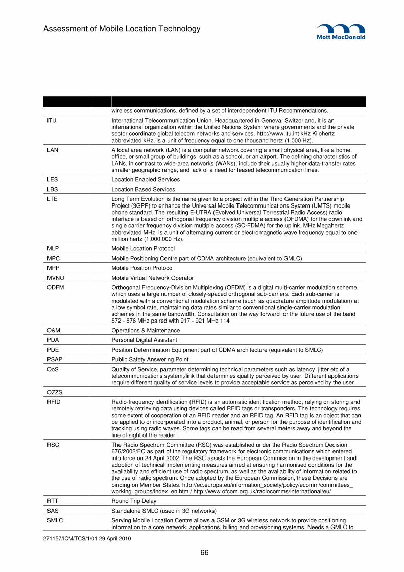
271157/ICM/TCS/1/01 29 April 2010
66
Assessment of Mobile Location Technology
wireless communications, defined by a set of interdependent ITU Recommendations.
ITU International Telecommunication Union. Headquartered in Geneva, Switzerland, it is an international organization within the United Nations System where governments and the private sector coordinate global telecom networks and services. http://www.itu.int kHz Kilohertz abbreviated kHz, is a unit of frequency equal to one thousand hertz (1,000 Hz).
LAN A local area network (LAN) is a computer network covering a small physical area, like a home, office, or small group of buildings, such as a school, or an airport. The defining characteristics of LANs, in contrast to wide-area networks (WANs), include their usually higher data-transfer rates, smaller geographic range, and lack of a need for leased telecommunication lines.
LES Location Enabled Services
LBS Location Based Services
LTE Long Term Evolution is the name given to a project within the Third Generation Partnership Project (3GPP) to enhance the Universal Mobile Telecommunications System (UMTS) mobile phone standard. The resulting E-UTRA (Evolved Universal Terrestrial Radio Access) radio interface is based on orthogonal frequency division multiple access (OFDMA) for the downlink and single carrier frequency division multiple access (SC-FDMA) for the uplink. MHz Megahertz abbreviated MHz, is a unit of alternating current or electromagnetic wave frequency equal to one million hertz (1,000,000 Hz).
MLP Mobile Location Protocol
MPC Mobile Positioning Centre part of CDMA architecture (equivalent to GMLC)
MPP Mobile Position Protocol
MVNO Mobile Virtual Network Operator
ODFM Orthogonal Frequency-Division Multiplexing (OFDM) is a digital multi-carrier modulation scheme, which uses a large number of closely-spaced orthogonal sub-carriers. Each sub-carrier is modulated with a conventional modulation scheme (such as quadrature amplitude modulation) at a low symbol rate, maintaining data rates similar to conventional single-carrier modulation schemes in the same bandwidth. Consultation on the way forward for the future use of the band 872 - 876 MHz paired with 917 - 921 MHz 114
O&M Operations & Maintenance
PDA Personal Digital Assistant
PDE Position Determination Equipment part of CDMA architecture (equivalent to SMLC)
PSAP Public Safety Answering Point
QoS Quality of Service, parameter determining technical parameters such as latency, jitter etc of a telecommunications system,/link that determines quality perceived by user. Different applications require different quality of service levels to provide acceptable service as perceived by the user.
QZZS
RFID Radio-frequency identification (RFID) is an automatic identification method, relying on storing and remotely retrieving data using devices called RFID tags or transponders. The technology requires some extent of cooperation of an RFID reader and an RFID tag. An RFID tag is an object that can be applied to or incorporated into a product, animal, or person for the purpose of identification and tracking using radio waves. Some tags can be read from several meters away and beyond the line of sight of the reader.
RSC The Radio Spectrum Committee (RSC) was established under the Radio Spectrum Decision 676/2002/EC as part of the regulatory framework for electronic communications which entered into force on 24 April 2002. The RSC assists the European Commission in the development and adoption of technical implementing measures aimed at ensuring harmonised conditions for the availability and efficient use of radio spectrum, as well as the availability of information related to the use of radio spectrum. Once adopted by the European Commission, these Decisions are binding on Member States. http://ec.europa.eu/information_society/policy/ecomm/committees_ working_groups/index_en.htm / http://www.ofcom.org.uk/radiocomms/international/eu/
RTT Round Trip Delay
SAS Standalone SMLC (used in 3G networks)
SMLC Serving Mobile Location Centre allows a GSM or 3G wireless network to provide positioning information to a core network, applications, billing and provisioning systems. Needs a GMLC to

271157/ICM/TCS/1/01 29 April 2010
67
Assessment of Mobile Location Technology
complete the function
SLP SUPL Location Platform
SRD A Short Range Device (SRD) is a general term, applied to various radio devices designed to operate over short range and at low power levels. This includes alarms, telemetry and telecommand devices, radio microphones, radio local area networks and anti-theft devices with maximum powers of up to 500 mW at VHF/UHF, as well as certain microwave/Doppler devices with maximum powers of up to 5 W. SRD normally operate on a non-protected, non-interference basis.
SS7 Signalling System 7, system for control in voice networks, essential for set-up and tear down of calls etc.
SUPL Secure user plane location, a standard that defines how location information is passed from the handset to for example a location based server, making use of user plane only, ie not using signalling/control plane
TDD Time Division Duplexing (TDD) refers to a transmission scheme in which a common carrier is shared between the uplink and downlink, the resource being switched in time. Users are allocated one or more timeslots for uplink and downlink transmission. Consultation on the way forward for the future use of the band 872 - 876 MHz paired with 917 - 921 MHz 115
TETRA The Terrestrial Trunked Radio (TETRA) standard (formerly known as Trans European Trunked RAdio) was developed by the European Telecommunications Standards Institute, (ETSI), as a digital alternative to analogue trunked systems. However, TETRA, with its enhanced encryption capability, has developed into a higher tier (Public Safety) product, currently mainly used by Governments, some Airports, emergency services and utilities.
TRX A Transceiver. A device that is capable of both transmission and reception of a signal.
TTFF Time To First Fix
UMTS Universal Mobile Telecommunications System (UMTS) is one of the third-generation (3G) mobile technologies and is included in IMT-2000. UMTS uses a wideband code division multiple access (W-CDMA) radio interface. The designation UMTS900 is used to differentiate UMTS operating the band 880 – 915 MHz and 925 – 960 MHz from UMTS operating in other frequency bands.
VoIP Voice over IP (internet protocol)
WAP Wireless Access Protocol. WAP is an open international standard[1] for application layer network communications in a wireless communication environment. Its main use is to enable access to the Internet (HTTP) from a mobile phone or PDA.
W-CDMA Wideband Code Division Multiple Access used in 3G technology (in Europe)
WGS-84 Standard scheme for defining a geographic location
WiFi A telecommunications technology that provides wireless transmission of data over short distances at low power unlicensed. The technology is based on the IEEE 802.11a,b,g standards
WLAN A local area wireless network in which a mobile user can connect to a local area network (LAN) through a wireless (radio) connection. The IEEE 802.11 group of standards specify the technologies for wireless LANs. 802.11 standards use the Ethernet protocol and CSMA/CA (carrier sense multiple access with collision avoidance) for path sharing and include an encryption method, the Wired Equivalent Privacy algorithm.
WiMAX Worldwide Interoperability for Microwave Access, is a telecommunications technology that provides wireless transmission of data using a variety of transmission modes, from point-to-point links to portable internet access. The technology is based on the IEEE 802.16 standard

271157/ICM/TCS/1/01 29 April 2010
68
Assessment of Mobile Location Technology
The LBS eco-system is well developed with suppliers for all parts of the systems.
Table 8.1: Table showing suppliers
Type of equipment/system Supplier Name Type of equipment/system
Supplier Name
SMLC/GMLC/SAS/MPC SignalSoft GIS ESRI
Openwave t TeleAtlas
Ericsson
Nokia In building layout Autodesk
Autodesk
True position Chipset Qualcomm
Intrade SiRF
SKT Broadcom
Openwave NXP
Andrew Atherost
Motorola
Andrew M2M LBS Siemens
Qualcomm Falcon
Telit
Source: Various, supplier websites etc.
Appendix H. Supplier list