Embed Size (px)
Citation preview
Assessment of Existing Structures in the Absence
of Drawings
Assessment of Existing Structures in the Absence
of Drawings
by
Keith Kesner, Ph.D., P.E., S.E.
2011 ICRI Spring Convention
Houston, Texas
by
Keith Kesner, Ph.D., P.E., S.E.
2011 ICRI Spring Convention
Houston, Texas
MotivationMotivation
• We have a need to evaluate existing structures– Prior to rehabilitation
– Changes in occupancy
– Sustainability compared to new construction
• Drawings are commonly not available– Lost over time
– Changes in ownership
GoalsGoals• As-built drawings
– Existing geometry
– Structure type
• Current conditions– Deterioration
– Variations from original construction
• Material properties
• Clear path forward – Analysis / building codes
IssuesIssues• Structural assessment
– Current conditions
– Member geometry
– Material properties• P = [K] Δ
• Φ Mn = Φ As fy (d-a/2) = Φ 0.85 f’c a b (d-a/2)
• Analysis requirements / limitations
• Building code requirements
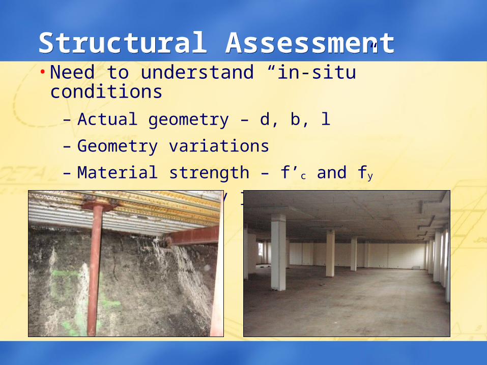
Structural AssessmentStructural Assessment• Need to understand “in-situ” conditions
– Actual geometry – d, b, l
– Geometry variations
– Material strength – f’c and fy
– Deterioration / loss of strength
Typical Conditions to VerifyTypical Conditions to Verify
• Verification / identification of member sizes
• Location and spacing of embedded items
– Mild reinforcing steel, post-tensioning, conduit
– Masonry ties and hardware
• Locating hidden flaws and defects (voids, trapped moisture, poor consolidation, etc.)
• Corrosion damage assessment
• Concrete properties
• Reinforcing steel properties
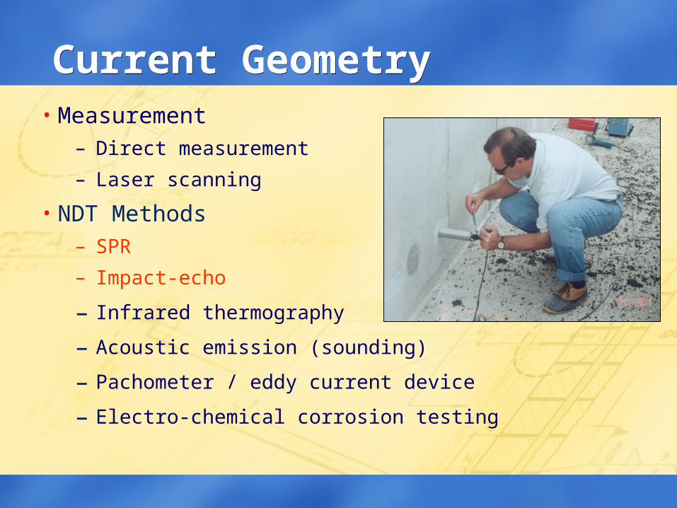
Current GeometryCurrent Geometry• Measurement
– Direct measurement
– Laser scanning
• NDT Methods– SPR
– Impact-echo
– Infrared thermography
– Acoustic emission (sounding)
– Pachometer / eddy current device
– Electro-chemical corrosion testing
NDT AdvantagesNDT Advantages• Access to hidden items – “see through walls”
• Better investigations with NDT
• Rapid accumulation of data
• Generally less expensive than destructive testing
• Minimize interruption of building services
• Evaluation and quality assurance
NDT DisadvantagesNDT Disadvantages
• More than one test method may be required
• Environmental conditions may effect or distort results
• Construction details & building components may effect results
• Some conditions cannot be determined with a reasonable degree of accuracy without destructive testing
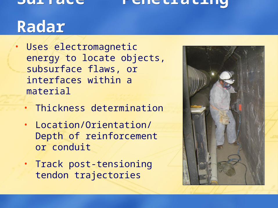
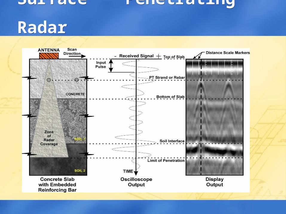
• Uses electromagnetic energy to locate objects, subsurface flaws, or interfaces within a material
• Thickness determination
• Location/Orientation/Depth of reinforcement or conduit
• Track post-tensioning tendon trajectories
Surface Penetrating RadarSurface Penetrating Radar
Surface Penetrating RadarSurface Penetrating Radar
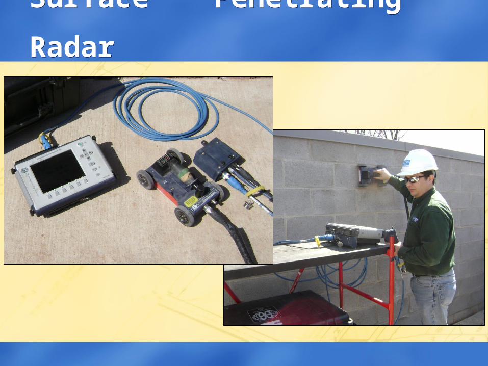
Surface Penetrating RadarSurface Penetrating Radar
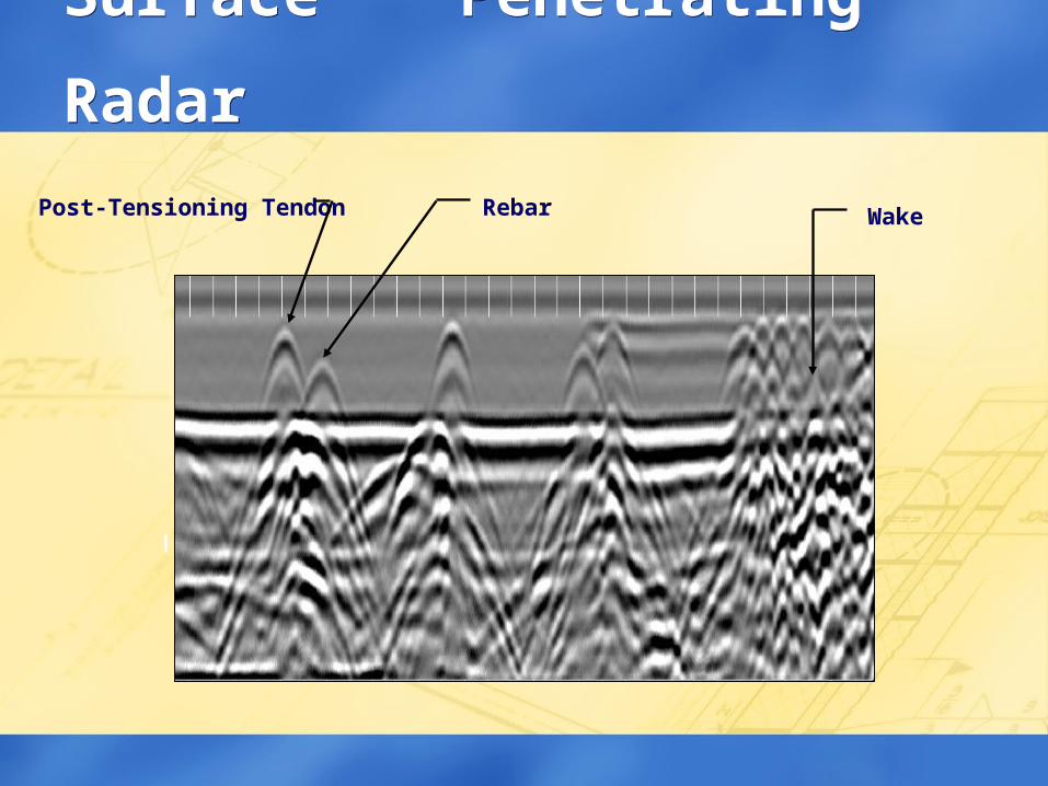
Post-Tensioning Tendon Rebar Wake
Surface Penetrating RadarSurface Penetrating Radar
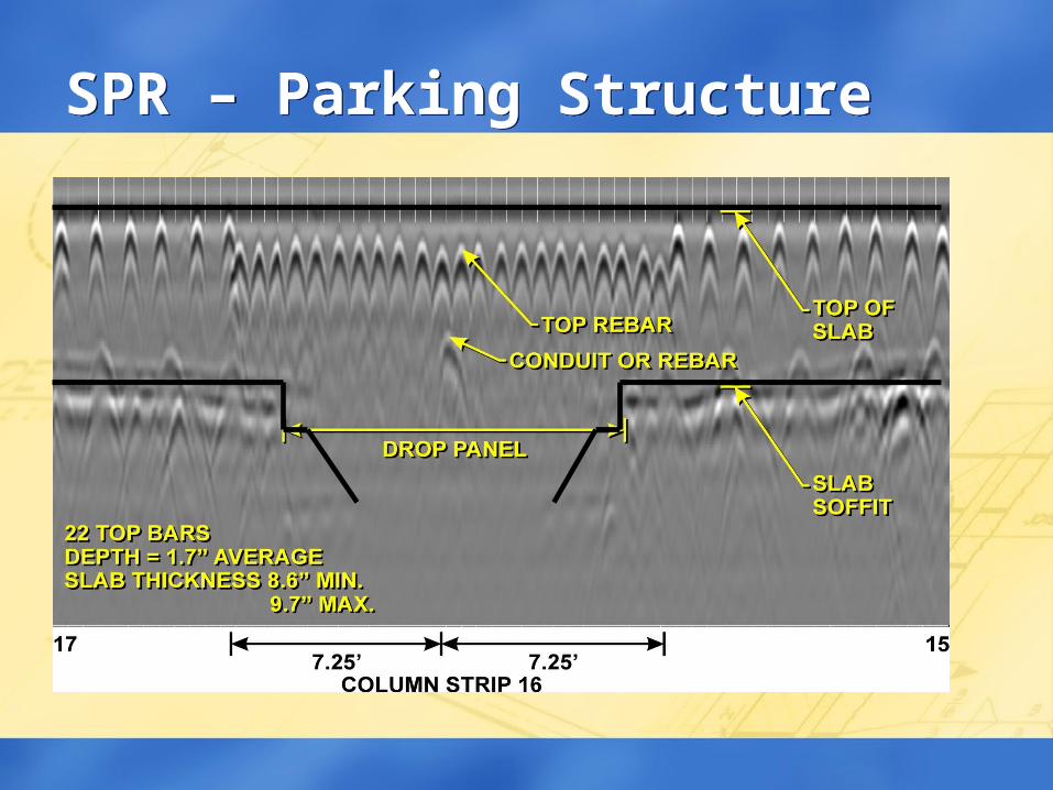
SPR – Parking StructureSPR – Parking Structure
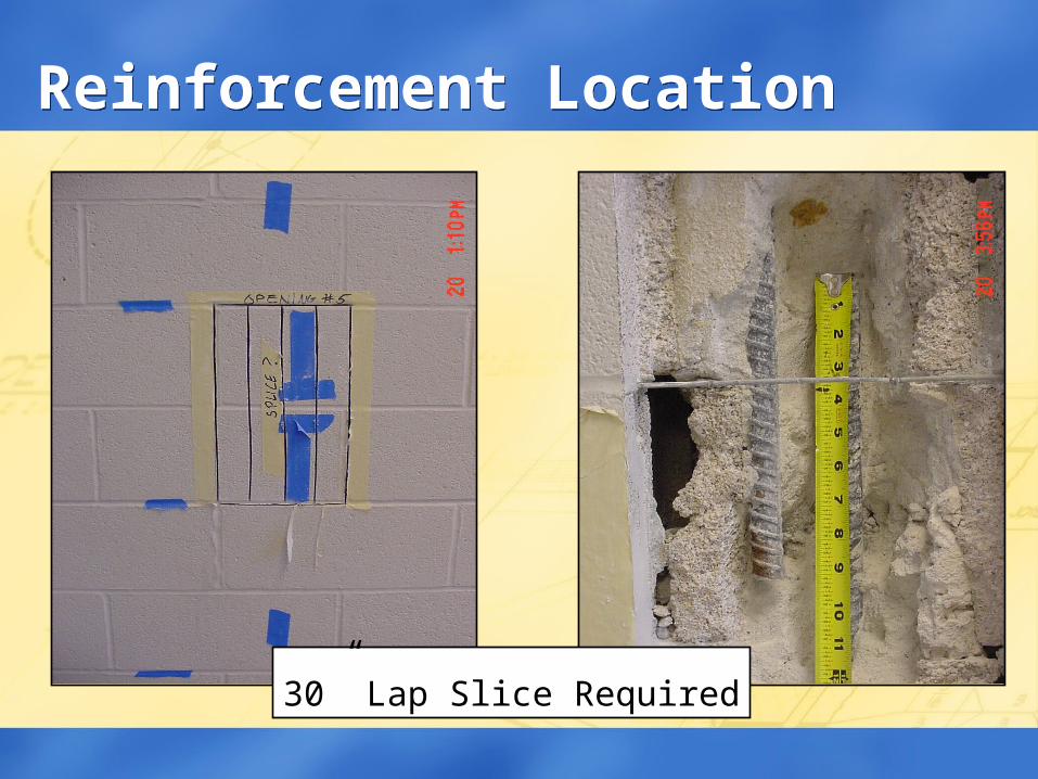
30” Lap Slice Required
Reinforcement LocationReinforcement Location
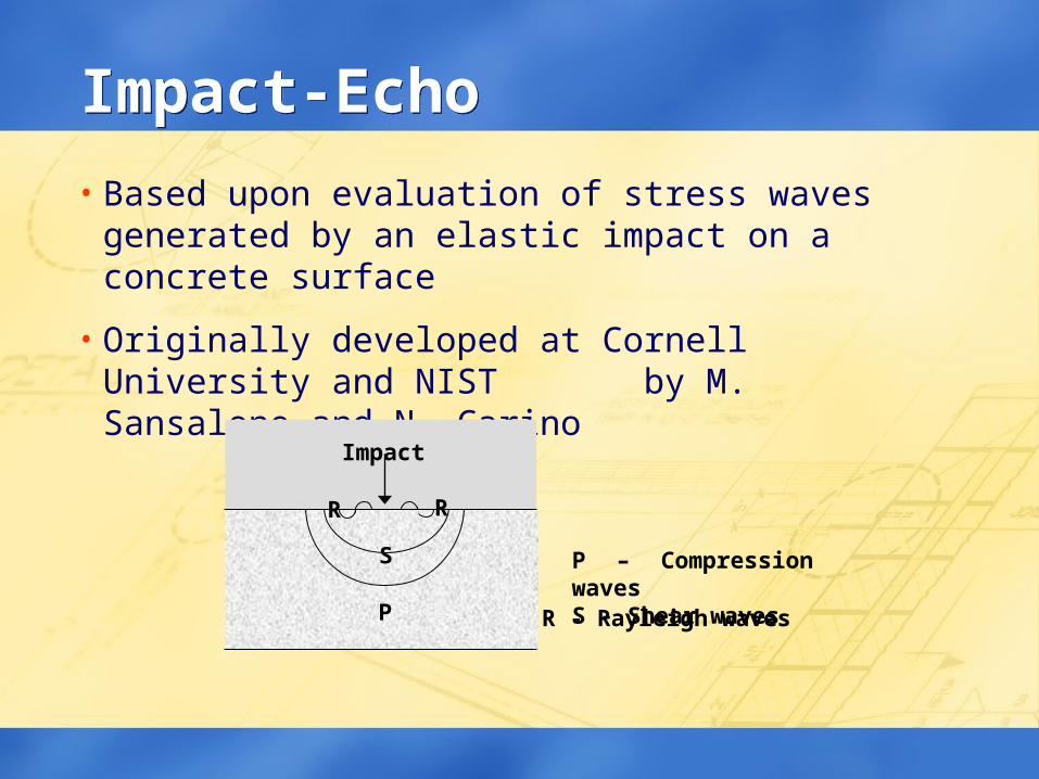
Impact-EchoImpact-Echo
• Based upon evaluation of stress waves generated by an elastic impact on a concrete surface
• Originally developed at Cornell University and NIST by M. Sansalone and N. Carino
P
S P – Compression wavesS - Shear wavesR - Rayleigh waves
RR
Impact
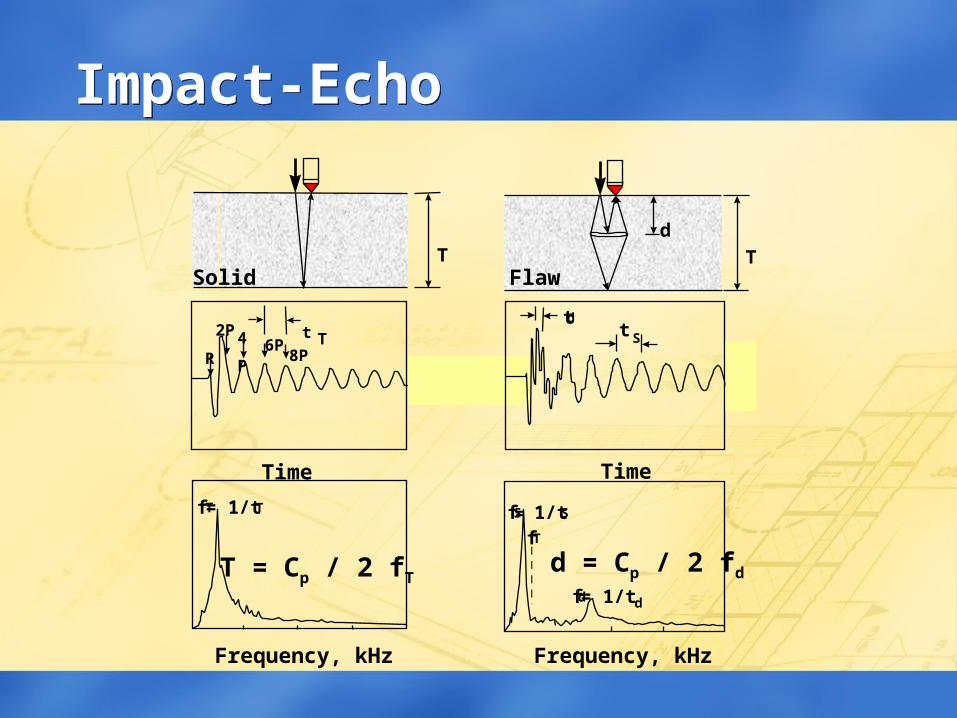
Impact-EchoImpact-Echo
= 1/t
T
Time
Frequency, kHz
fT T
t TR
2P 4P 6P8P
T = Cp / 2 fT
Solid
d
Frequency, kHz
Time
tdt
S
fS = 1/t S
fT
fd = 1/t d
T
d = Cp / 2 fd
Flaw
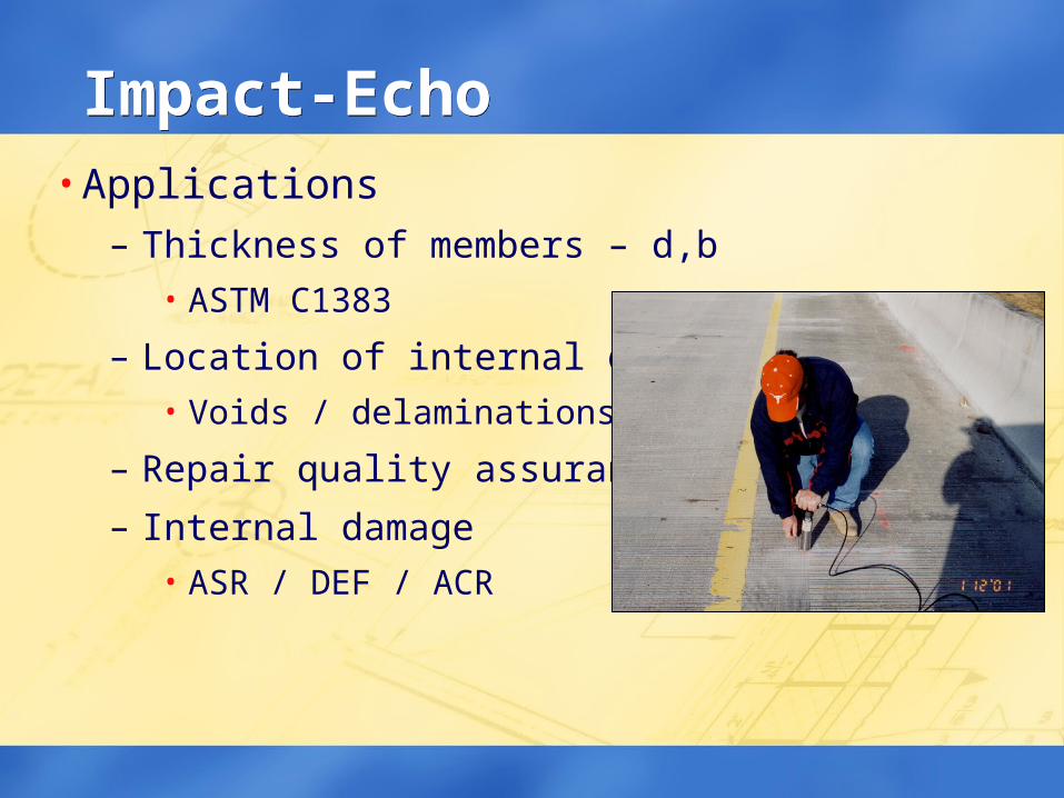
Impact-EchoImpact-Echo• Applications
– Thickness of members – d,b• ASTM C1383
– Location of internal defects• Voids / delaminations
– Repair quality assurance
– Internal damage• ASR / DEF / ACR
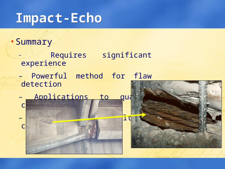
Impact-EchoImpact-Echo
• Summary– Requires significant experience
– Powerful method for flaw detection
– Applications to quality control
– Verification of results is critical
IssuesIssues• Structural assessment
– Current conditions
– Member geometry
– Material properties
• Analysis requirements / limitations
• Building code requirements
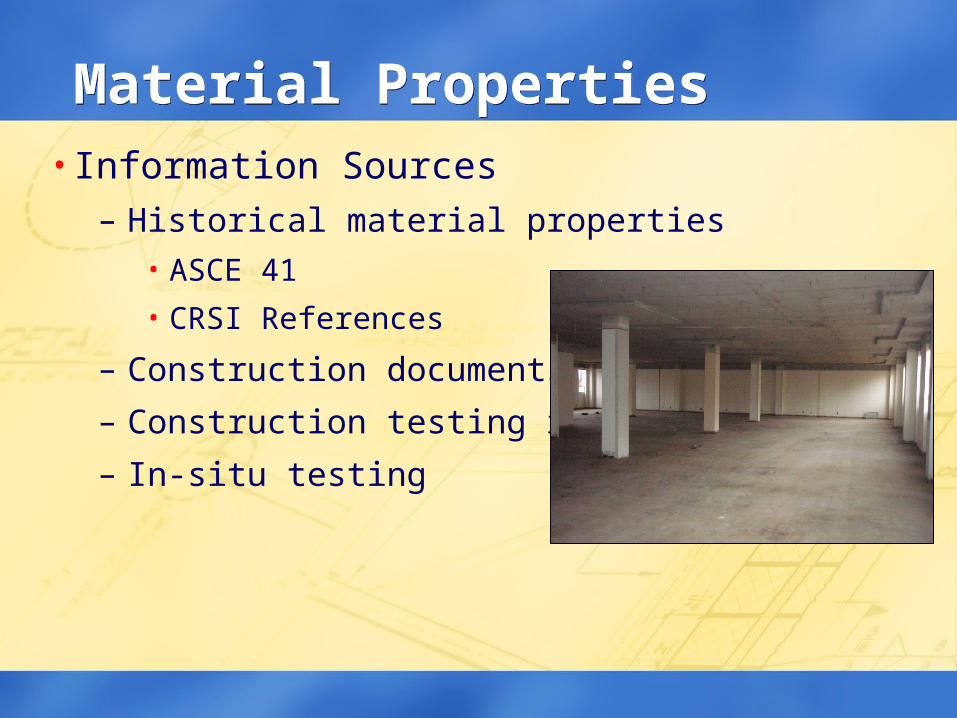
Material PropertiesMaterial Properties• Information Sources
– Historical material properties • ASCE 41
• CRSI References
– Construction documents
– Construction testing records
– In-situ testing
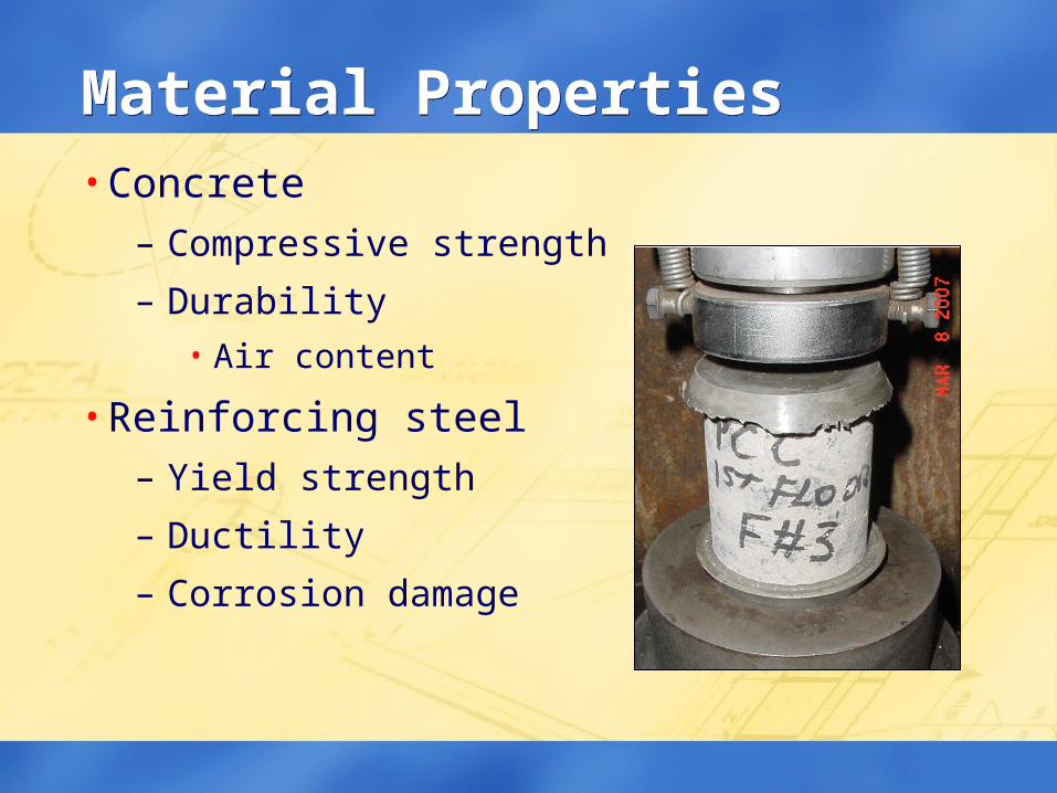
Material PropertiesMaterial Properties• Concrete
– Compressive strength
– Durability• Air content
• Reinforcing steel– Yield strength
– Ductility
– Corrosion damage
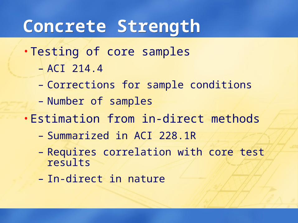
Concrete StrengthConcrete Strength• Testing of core samples
– ACI 214.4
– Corrections for sample conditions
– Number of samples
• Estimation from in-direct methods– Summarized in ACI 228.1R
– Requires correlation with core test results
– In-direct in nature
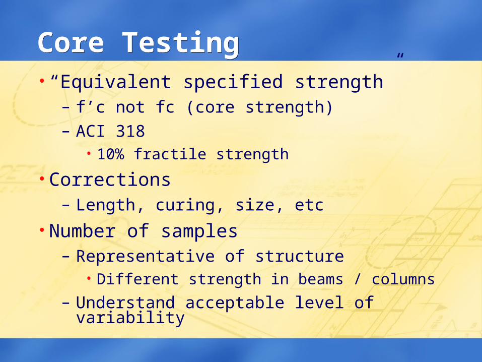
Core TestingCore Testing• “Equivalent specified strength”
– f’c not fc (core strength) – ACI 318
• 10% fractile strength
• Corrections– Length, curing, size, etc
• Number of samples– Representative of structure
• Different strength in beams / columns
– Understand acceptable level of variability
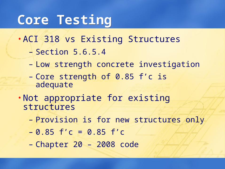
Core TestingCore Testing• ACI 318 vs Existing Structures
– Section 5.6.5.4
– Low strength concrete investigation
– Core strength of 0.85 f’c is adequate
• Not appropriate for existing structures– Provision is for new structures only
– 0.85 f’c = 0.85 f’c
– Chapter 20 – 2008 code
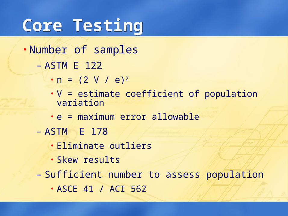
Core TestingCore Testing• Number of samples
– ASTM E 122• n = (2 V / e)2
• V = estimate coefficient of population variation
• e = maximum error allowable
– ASTM E 178• Eliminate outliers
• Skew results
– Sufficient number to assess population• ASCE 41 / ACI 562
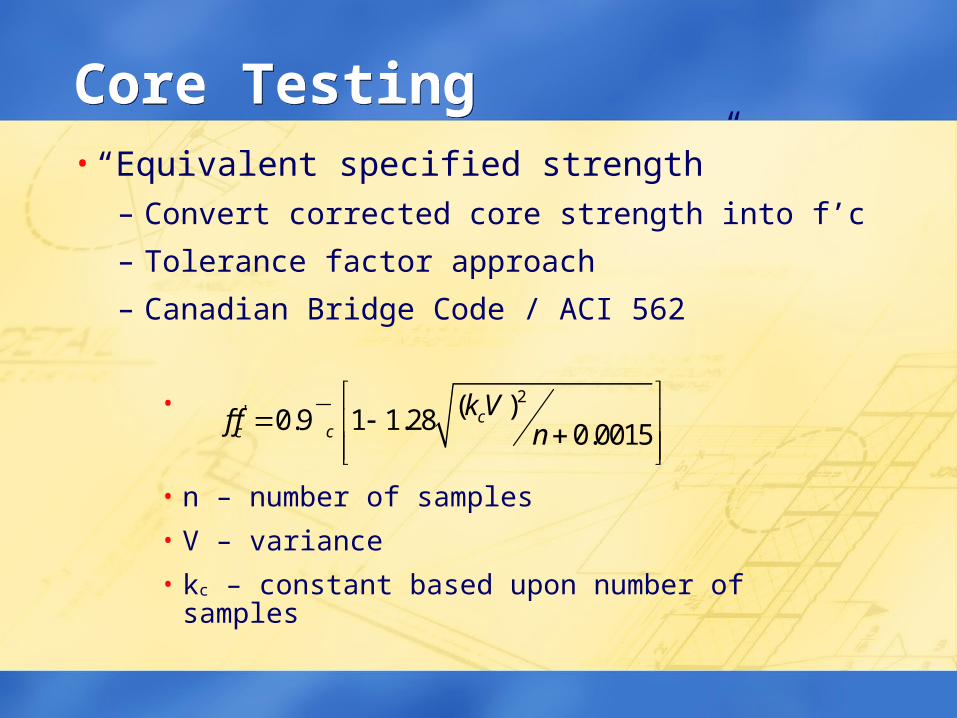
Core TestingCore Testing• “Equivalent specified strength”
– Convert corrected core strength into f’c
– Tolerance factor approach
– Canadian Bridge Code / ACI 562
•
• n – number of samples
• V – variance
• kc – constant based upon number of samples
2' ( )0.9 1 1.28 0.0015
cc c
k Vf f n
Estimation of Concrete StrengthEstimation of Concrete Strength• ACI 228.1
• Test methods – require correlation with cores– Probe / Pin penetration – ASTM C 803
– Pull out tests – ASTM C 900
– Pulse velocity – ASTM C 597
– Rebound hammer – ASTM C 805
• Faster than core testing– More samples can be tested
– Identify low strength areas
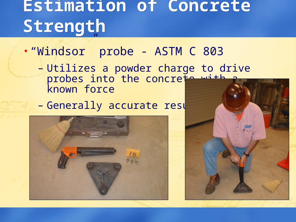
Estimation of Concrete StrengthEstimation of Concrete Strength• “Windsor” probe - ASTM C 803
– Utilizes a powder charge to drive probes into the concrete with a known force
– Generally accurate results
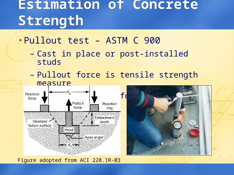
Estimation of Concrete StrengthEstimation of Concrete Strength• Pullout test – ASTM C 900
– Cast in place or post-installed studs
– Pullout force is tensile strength measure
– Common in UK for form stripping
Figure adopted from ACI 228.1R-03
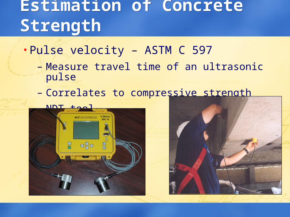
Estimation of Concrete StrengthEstimation of Concrete Strength• Pulse velocity – ASTM C 597
– Measure travel time of an ultrasonic pulse
– Correlates to compressive strength
– NDT tool
Estimation of Concrete StrengthEstimation of Concrete Strength
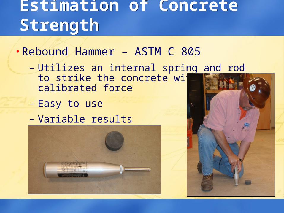
• Rebound Hammer – ASTM C 805– Utilizes an internal spring and rod to strike the
concrete with a calibrated force
– Easy to use
– Variable results
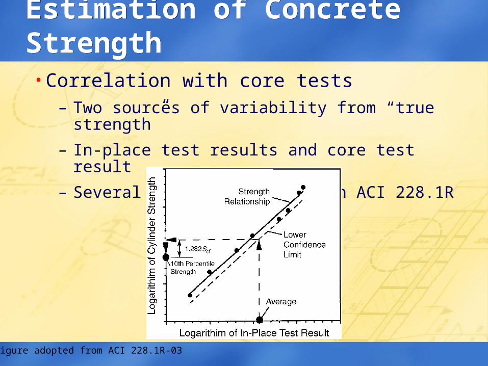
Estimation of Concrete StrengthEstimation of Concrete Strength• Correlation with core tests
– Two sources of variability from “true strength”
– In-place test results and core test result
– Several methods presented in ACI 228.1R
Figure adopted from ACI 228.1R-03
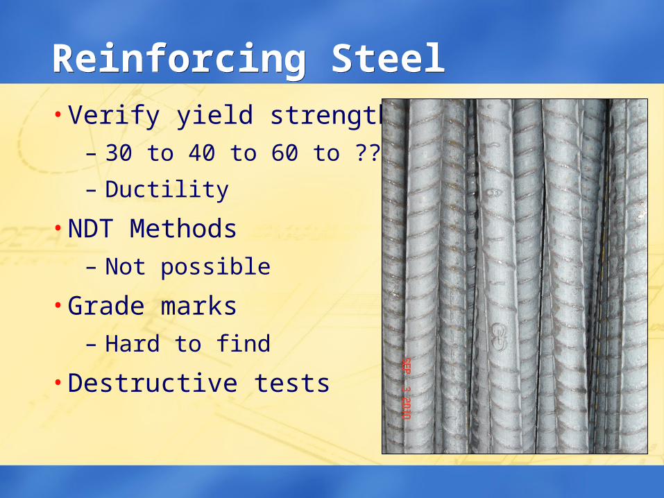
Reinforcing SteelReinforcing Steel• Verify yield strength
– 30 to 40 to 60 to ??ksi
– Ductility
• NDT Methods– Not possible
• Grade marks– Hard to find
• Destructive tests
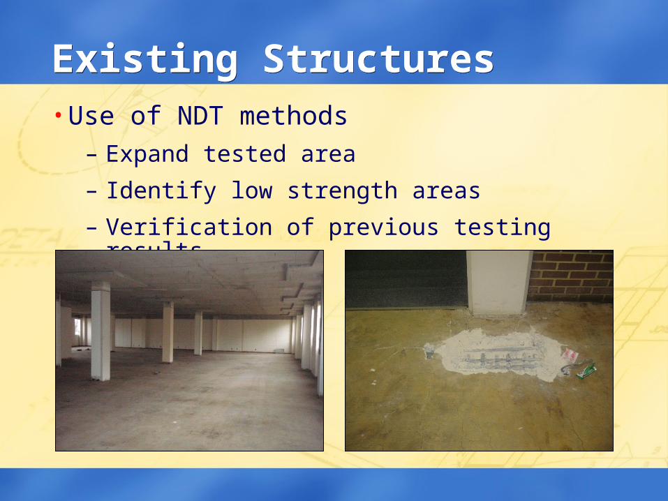
Existing StructuresExisting Structures• Use of NDT methods
– Expand tested area
– Identify low strength areas
– Verification of previous testing results
IssuesIssues• Structural Assessment
– Current conditions
– Member geometry
– Material properties
• Analysis Requirements / Limitations
• Building Code Requirements
Analysis IssuesAnalysis Issues• Capacity of Existing Structure
– Account for in-situ conditions
– Account for actual material properties
– Account for construction process
• Design for “future” loads
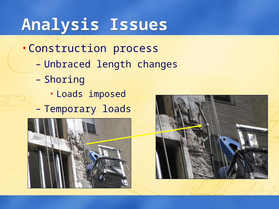
Analysis IssuesAnalysis Issues• Construction process
– Unbraced length changes
– Shoring• Loads imposed
– Temporary loads
Load TestingLoad Testing• Valid method to assess existing structures
• Supplement analysis results
• ACI 437– Load magnitude
– Duration
– Standard in development
Building Code IssuesBuilding Code Issues• Project specific assessment
• When do current code requirements have to be satisfied?
– Grandfather clause?
– Seismic requirements?
– Energy codes?
• IBC Codes– Chapter 34 – Existing Structures
– 5% rule
ACI 562ACI 562• Concrete repair code
– Under development
– Expect completion in 2012
– Parallel to ACI 318 for repair
– Adopt into IEBC or IBC
• Code requirements not guidelines– Evaluation
– Repair design
– Quality control
SummarySummary• Existing structures commonly encountered
– Lack of design / construction documents
– Need to preserve / protect these structures
• Assessment – Numerous methods exist
– Generally project specific
• Analysis / Codes– More involved than new structures

Thank YouThank You
QUESTIONS?