Embed Size (px)
Citation preview

Build v2.11
Side-Mount
Version
Note: Prior to assembly, be sure to remove all printing pads from
the printed parts and also be sure to sort through and organize all
of your hardware before assembly – this will help ensure you are
using the proper length screws in the proper locations!
Assembly Instructions

Side-Mount Version - Uses identical Hot-End Sub-Assemblies as Rear-Mount Version
- Moves Nozzle Closer to X-Axis Rails (Increasing Compatibility
with Various i3 Frames such as the P3 Steel)

1
Remove 4x designed-in print support ribs from 2.1-FM-extruderbase.stl
2.1-FM-extruderbase.stl
2 Attach 3X JST 2W Male connectors to the extruder base using 2.1-FM-conncover-base.stl and 2x #2-32 x 3/8” Self Tapping Screws
2.1-FM-conncover-base.stl
#2-32 x 3/8 screw
#2-32 x 3/8 screw
Note: Be sure 3x Male Connectors are aligned to notches in both extruderbase and connector cover
Note: Do not over-tighten self-tapping screws. They work perfectly fine if they are just nice and snug.

2x #2-32 x 3/8 screws
Finish attaching connector cover to the extruder base with 2x #2-32 x 3/8” Self Tapping Screws.
Proper Connector Orientation
3

4 Press-fit 625zz Radial Bearing until flush with print-bed surface on extruderbase
625zz Radial Bearing Extruder Base Print-bed Surface
5
Press-fit 4mm OD PTFE Tubing into filament access hole.
PTFE Tubing 4.0-O.D. 2.0-I.D.
Note: You may need to slowly run a ~4.0mm drill-bit through hole to clean it up before press-fitting tube in place. If you over-drill the hole, try gluing the PTFE tubing in place or re-printing the extruder base.
Note: Pressing the PTFE tubing too far into the extruder housing, may cause it to interfere with the drive gear or idler bearing. If this happens, simply trim the excess PTFE tubing with a razor blade.
Note: To keep the bearing true, it is best to use a flat surface and set the bearing down on it. Simply press the extruder base down over the bearing until it hits the flat surface - ensuring that the bearing does not tilt as it goes into the bearing holder hole.

Attach 2.1-FM-gearprotector.stl using 2x #2-32 x 3/8” and 1x #2-32 x 5/16” Self Tapping Screws
#2-32 x 5/16 screw
2.1-FM-gearprotector.stl
#2-32 x 3/8 screw
#2-32 x 3/8 screw
6
7
NEMA-14 Stepper Motor
3x M3 PTFE Washer
3x PTFE Tubing 5mm OD, 3mm ID, 9.25 Length
3x 1/8” Blind Rivet
Washer
3x M3x16 Machine
Screw
Note: PTFE tubing, washers and NEMA-14 gasket (shown in the red highlighted portion of Fig1.1 to the left) provide an excellent thermal insulator between the NEMA-14 stepper motor and the plastic extruder assembly mount (PTFE washers are rated at 500 degrees Celsius).
Fig. 1.1
Install NEMA-14 stepper motor exactly as shown. Note: NEMA-14 wires should exit the motor at the bottom toward the print bed.
Note: orient wires toward print bed
NEMA-14 Gasket
Note: There is no need to install the NEMA-14 motor tightly yet, leave it a tad loose for gear-gear adjustment later

8 Loosely install Toranado 19T Motor Pinion
onto NEMA-14 stepper motor shaft Note: Do not yet fully tighten gear to shaft. Access hole can be used later for fine tuning the gear position before tightening.
9 Install 2.1-FM-idlertensioner.stl
using 2x M3x30 machine screw, 2x Springs and 2x M3 nyloc nuts
2x M3x30 Machine
Screw 2x Springs
2.1-FM-idlertensioner.stl
2x M3 Nyloc Nut

10 Install 2.1-FM-40mmduct.stl to 2.1-FM-lowercover.stl using 2x #2-32 x 3/8 Self Tapping Screws
#2-32 x 3/8 screw
#2-32 x 3/8 screw 2.1-FM-lowercover.stl
2.1-FM-40mmduct.stl
11 Attach lower cover assembly using 1x
#2-32 x 3/8” and 1x #2-32 x 5/16” Self Tapping Screw
#2-32 x 3/8 screw
#2-32 x 5/16 screw
Lower Cover Assembly Note: BL Touch Users will print and use 2.1-FM-lowercover-bltouch.stl
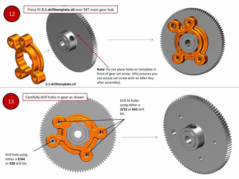
12 Press-fit 2.1-drilltemplate.stl over 94T main gear hub
13 Carefully drill holes in gear as shown
Drill 3x holes using either a 3/32 or #42 drill bit.
Drill hole using either a 9/64 or #28 drill bit.
Note: Do not place holes on template in front of gear set screw (this ensures you can access set screw with an Allen Key after assembly). 2.1-drilltemplate.stl

14 Install 50mm shaft onto drive gear
and tighten set screw
5mm Dia. Shaft – 50mm
length Note: Shaft should be flush with outer face of gear.
15
Attach 2.1-FM-gearcover.stl using 3x #2-32 x 5/16” Self Tapping
Screws
#2-32 x 5/16 screw
#2-32 x 5/16 screw
#2-32 x 5/16 screw
2.1-FM-gearcover.stl

16
Install 2x M3 Nuts into captive nut clots as shown.
2x M3 Nuts

17 Install 94T Main Gear Assembly and
MK7 Drive Gear Note: Loosely tighten Mk7 Drive gear, final adjustment and tightening will be made at final extruder assembly.
MK7 Drive Gear

17a *Other Possible Gear Configurations for v2.1
Version 1.0 Acetal (Delrin) Gearset Version 1.1 Aluminum Gearset
Print and use 1.0-spacer.stl Use a Stainless Steel M5 Washer
(*Rear-Mount Version Shown)

18 Press-Fit MR685ZZ Radial Bearing
into 2.1-FM-bearingholder.stl
Note: To keep the bearing true, it is best to use a flat surface and set the bearing down on it. Simply press the bearing holder down over the bearing until it hits the flat surface - ensuring that the bearing does not tilt as it goes into the bearing holder hole.
19
Install Bearing Holder Assembly
20
Install 2.1-washer-M5.stl and 5mm Shaft Collar and tighten set screw.
2.1-FM-bearingholder.stl
2.1-washer-M5.stl
5mm Shaft Collar
Note: Tightly hold entire extruder gear-set together onto extruder when tightening shaft collar set screw.
Option: If you don’t have the 5mm shaft collar, you can print 2.1-shaftcollar.stl and mount it to the shaft w/ an M3x3mm set screw.
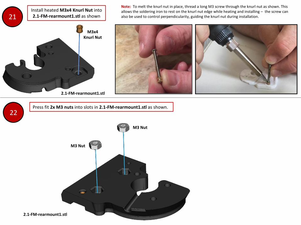
Note: To melt the knurl nut in place, thread a long M3 screw through the knurl nut as shown. This allows the soldering iron to rest on the knurl nut edge while heating and installing – the screw can also be used to control perpendicularity, guiding the knurl nut during installation. 21
Install heated M3x4 Knurl Nut into 2.1-FM-rearmount1.stl as shown
22 Press fit 2x M3 nuts into slots in 2.1-FM-rearmount1.stl as shown.
2.1-FM-rearmount1.stl
M3 Nut
M3x4 Knurl Nut
2.1-FM-rearmount1.stl
M3 Nut

23 Loosely Install Rear Mount Assembly and 2.1-FM-rearmount2.stl using 2x #4-20 x 3/4”, 1x #4-20 x 5/8” and 1x #2-32 x 5/16 Self Tapping Screws.
Note: Do not yet fully-tighten self-tapping screws – leave them slightly loose to allow cover adjustment in next step. Be sure screws are used in proper places to avoid damage to PTFE tubing
2.1-FM-rearmount2.stl
Rear Mount Assembly
#4-20 x 3/4” Self Tap Screw
#4-20 x 3/4” Self Tap Screw
#4-20 x 5/8” Self Tap Screw
#2-32 x 5/16 screw

24 Insert 2.1-FM-idlerholder.stl into extruder and fasten it in
place with a M3x40mm screw.
2.1-FM-idlerholder.stl
Note: Fastening the M3x40mm screw in place before tightening the decoration cover helps align system for hot-end installation and removal.
M3x40 Screw
25
Fully tighten Rear Mount Assembly onto extruder by fully tightening self tapping screws from Step #23. After fully-tightening cover, remove M3x40mm screw and 2.1-FM-idlerholder.stl
Fully-tighten 4x screws

26
Install 40x40x15mm Delta Bed Cooling Fan 2.1-FM-40mmfancover.stl with 4x #4-20 x
3/4” Self Tapping Screws
4x #4-20 x 3/4” Self Tap Screws
40x40x15mm Delta AFB0412SHB cooling fan
27 Adjust gear-gear positioning by adjusting motor position and
tightening 3x M3x16 motor mount bolts.
3x M3x16 motor mount bolts
Note: The goal in this step is to adjust
the motor and ensure the gap between
gears is suitable. Once the motor is fully
tightened, there should be EVER SO
SLIGHT of gap between the two gears
and they should rotate freely without
binding. If this is not done properly,
bound gears could cause the extruder
motor to bind up and miss steps.
Adjust motor position
Note: After your first long print, you
should slightly re-tighten your motor
mount bolts after the motor has set in
place.
2.1-FM-40mmfancover.stl

28 Install 2.1-FM-smallgearcover.stl with 2x #2-32 x 5/16 self tapping screws
#2-32 x 5/16 self tap screw
#2-32 x 5/16 self tap screw
2.1-FM-smallgearcover.stl
29 Install heated M3x4 Knurl Nut into 2.1-FM-30mmfanmount.stl using
same method as shown in Step #22.
M3x4 Knurl Nut
2.1-FM-30mmfanmount.stl
30 Attach 2.1-FM-30mmfanmount.stl to
2.1-FM-idlerholder.stl using #2-32 x 3/8” Self Tapping Screw.
#2-32 x 3/8 screw
2.1-FM-idlerholder.stl

31
Press-fit assembled E3D-v6 hot-end into
assembly.
Note: The v2.1+ Toranado Extruder accepts genuine E3Dv6 1.75mm Hot-ends, as well as clone versions sold via eBay (clone version with threaded PTFE tube-holder shown).
2x M3 Nuts
E3d-V6 Hot-end Assembly 2.1-FM-30mmvent.stl
32
Install 2x M3 nuts into slots on 2.1-FM-30mmvent.stl
33 Attach 2.1-FM-30mmvent.stl using 2x
M3x30 machine screws and 2x #2-32 x 3/8” Self Tapping Screws
M3x30 screw
M3x30 screw
#2-32 x 3/8 screw
#2-32 x 3/8 screw Note: Tighten these 2x Machine Screws tightly as they are designed to clamp the hot-end in place on the assembly.
Note: Tighten these 2x self-tapping screws snugly, but do not over-tighten - they are in a delicate area on the 30mm vent and you don’t want to crack the plastic!

Note: Be sure to apply even pressure when self-threading machine screws. Do not over-tighten, just seat screw snugly. Idler should move freely but not wobble too much when screw is seated properly.
34 Insert 6255zz radial bearing onto 2.1-FM-idler.stl using 25mm long
5mm diameter shafting.
625zz Radial Bearing
5mm dia. shaft – 25m
length
35
Attach idler assembly using
M3x22 machine screw
2.1-FM-idler.stl
M3x22 Screw
36 Install 30mm cooling fan and 2.1-FM-30mmfancover.stl using
4x #4-20 x ¾” Self-Tapping Screws
4x #4-20 x 3/4 Self-Tapping
Screws
2.1-FM-30mmfancover.stl
30x30x10mm Cooling Fan
Note: Proper 30mm fan wire exit location

37 Insert 3x JST Female Connectors into
hot-end assembly slot locations
3x JST Female Connectors
JST Female Connector
Notch in plastic
captures nub on JST female
connector.
Wires routed in this area
Note: The JST connectors come with cut leads making them perfect for connecting your devices. With the JST connectors in place, begin planning and measuring the lengths for trimming the wires and connecting them to your Thermistor, 30mm Cooling Fan and Heater Cartridge. I recommend soldering the connections and using heat-shrink tubing over the wiring, and then zip-tying them in place in the slot location noted below.
Wire-routing channel
Location for Zip Tie
Recommended: When routing 30mm fan wires to back of assembly, use super-glue or some other adhesive in this area to isolate 30mm fan wires from heater-block.

38
After wiring is routed and connected, install 2.1-FM-conncover-he.stl with 2x #2-32 x 3/8” Self Tapping
Screws
2x #2-32 x 3/8 self-tap screws
39
Align Hot-End Assembly with dovetail slots in
housing and press-fit into place.
Dovetail slots are located on both
extruder housing and hot-end assembly.
2.1-FM-conncover-he.stl

40 Install M3x40 screw and tighten
firmly to extruder housing. 41
Install 1.75mm filament.
Use filament to properly align MK7 drive gear. Fully tighten drive gear to shaft.
42
Close idler, mount your v2.1 Toranado to your
printer… be happy.
MK7 Drive Gear

Optional: BL-Touch
Version

18a Hot-End Removal Instructions
1. Remove filament and open drive gear access.
2. Remove M3x40mm Hot-End Containment Screw
3. Insert same 40mm screw into jack-nut location and use it to unseat hot-end assembly from connection system in back.
4. Remove Hot-End From Extruder.

beautiful.
Standard Side-Mount
Version
Side-Mount Version
with BL-Touch