Embed Size (px)
Citation preview
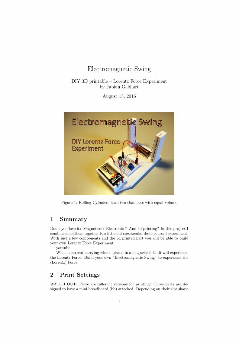
Electromagnetic Swing
DIY 3D printable – Lorentz Force Experimentby Fabian Gebhart
August 15, 2016
Figure 1: Rolling Cylinders have two chambers with equal volume
1 Summary
Don’t you love it? Magnetism? Electronics? And 3d printing? In this project Icombine all of them together to a little but spectacular do-it-yourself experiment.With just a few components and the 3d printed part you will be able to buildyour own Lorentz Force Experiment.
youtubeWhen a current-carrying wire is placed in a magnetic field, it will experience
the Lorentz Force. Build your own “Electromagnetic Swing” to experience the(Lorentz) Force!
2 Print Settings
WATCH OUT: There are different versions for printing! Three parts are de-signed to have a mini breadboard (bb) attached. Depending on their slot shape
1
for the magnet they are called:
1. electromagnetic swing bb rect.stl (with rectangle slot, like seen in video)
2. electromagnetic swing bb circ.stl (with circle slot)
3. electromagnetic swing bb flat.stl (without slot) and there is another part,which comes without any breadboard slot:
4. electromagnetic swing.stl
Printing with ABS worked fine, so all dimensions fit perfectly. Use supportrafts for the magnet spacing on the bottom side.
3 How I Designed This
When I first saw the electromagnetic swing back in my schooldays I was like”wow thats like magic”! So because I didn’t forget about that experiment Idecided to design one on my own. There you go, thats the ”ElectromagneticSwing - DIY Lorentz Force Experiment”.
The given parts are designed using Autodesk Inventor. The design wasconstrained so the battery and the breadboard would fit in the frame nicely.
4 Project: Electromagnetic Swing - DIY LorentzForce Experiment
4.1 Overview & Background:
This project is all about electromagnetism. It is easy to print and build, sostudents are able to complete this project on their own. Depending on thegoal of the lesson you can choose between the version with and the versionwithout the breadboard slot. If you want to present the impact of the Lorentzforce phenomenological, you are fine using the small part without breadboardslot. If you are looking for a nice experiment to show, experience and evencalculate (see below) the Lorentz force, you definitely go for the bigger versionwith breadboard slot.
4.1.1 Objectives:
Students will experience the impact of the electromagnetic Lorentz force. Bybuilding the project on their own they will have a hands-on project to learnabout the construction of an electric circuit, soldering and they will get a un-derstanding for magnetism and electromagnetism.
4.2 Audiences:
Students at the age of 11-16 in physics or science.
4.3 Subjects:
This project is a physics / science project for high school classes.
2

4.4 Skills Learned (Standards):
Students building and interact with this project are going to learn:
• the basic electronical laws
• the physics of magnets
• the physics of electromagnetism
• the construction of an electric circuit
• the characteristics of the Lorentz force
• soldering skills
• Trigonometry
• understanding of the orientation conventions for vectors in three dimen-sions
4.5 Lesson/Activity:
4.5.1 How to build the Electromagnetic Swing
To complete this project you need the following things (see pictures in gallery):For the part without breadboard:
• 3d printed part
• 9V battery
• 2 magnets (preferably 1 strong and 1 small)
• about 2x 30cm of wire
• copper wire about 5cm
For the part with breadboard you have to add:
• 3d printed part (with breadboard slot)
• mini Breadboard (about 34 x 45mm)
• jumper wire
• potentiometer 1k
• LED (1.85-2.5V at about 20mA current)
• resistor (1kOhm)
• plus whatever you want to add
I recommend buying strong neodym magnets, since you’ll get bigger effects.The magnets I’m using are the size 40 x 20 x 5 mm and the ring magnet is 10x 5 mm. But of course you can use just any magnets you have lying around orprefer.
3
4.5.2 Construction
First you have to print the part of your choice. I will show you how to constructthe part with breadboard slot since it also covers the whole construction of theone without breadboard slot.
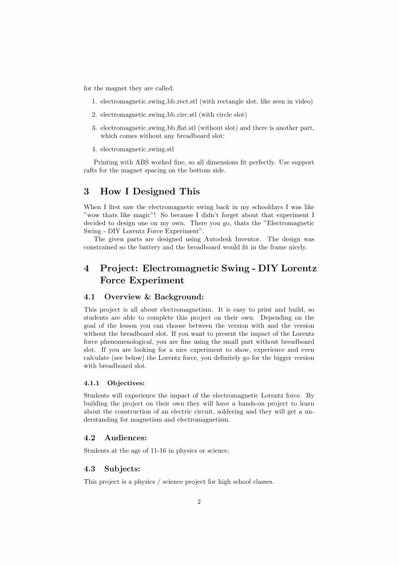
Make sure to safely remove the support raft at the bottom of the part.After placing the magnets on the appropriate positions you have to prepare
the swing. Therefore cut the wire to the wanted length and solder it to thecopper wire.
Thread the wire through the given holes in the 3d printed part and makesure the swing is as close as possible to the magnet, but without touching it.
Now prepare the battery connection. If you don’t have any plugs for the 9Vbattery, you might just safely open an old battery to remove the connection anduse it as a plug for your circuit. Doing so you now can solder the correspondingwires to the plug. Use heat shrink tube and breadboard pins to make user-friendly jacks.
(a) Savely remove the support rafts (b) solder the wire to the copper swing
(c) use heat shrinking tube to get nice jacks (d) thread the wire through the given holes
Figure 2: Preparation of the electromagnetic swing
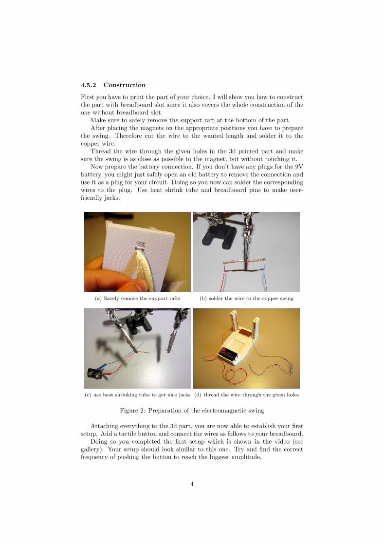
Attaching everything to the 3d part, you are now able to establish your firstsetup. Add a tactile button and connect the wires as follows to your breadboard.
Doing so you completed the first setup which is shown in the video (seegallery). Your setup should look similar to this one. Try and find the correctfrequency of pushing the button to reach the biggest amplitude.
4
(a) circuit 1 (b) circuit 2
(c) setup with one button (d) setup with button, potentiometer andLED
Figure 3: Two options of setting up the circuit
Now take the resistor, led and potentiometer. Connect them as shown inthe following picture in order to get the second setup running.
Once the second setup is established you should take some time to play withit. Smoothly turn the potentiometer to have the swing moved slowly. Yoursetup should now look similar to this one.
Now you know how things are going. If you have more ideas of what wecould add in the circuit – let me know. I would love to hear of people using andimproving the project in order to have a great experiment for the students.
4.5.3 Physics:
Since physics in this project are not just trivial, I want to add some informationabout it. You may see this as guidance to your presentation / lessen using theElectromagnetic Swing.
5
4.5.4 Lorentz Force:
The Lorentz force is the combination of electric and magnetic force. It resultsfrom the interaction between the electromagnetic fields.
According to Maxwells equations of classical electrodynamics a changingelectrical field leads to a magnetic field. Therefore a moving charge q surroundedby a magnetic field will experience a force F, called the Lorentz force:
~FL = q(~v × ~B)
Since we know current I is equals the charge per time
I =q
t
And the velocity is:
~v =~l
t
We get:4
~FL = q(~v × ~B) = I(~l × ~B)
This looks more applicable to our setup. The following calculations are forsure just rough calculations. With the given setup it is not possible to makeexact calculations. We just want to have a rough idea about the dimensions ofthe quantities we are dealing with. If you want to teach this kind of calculationto some students be sure to always have some error estimation afterwards.
So let’s see. Measuring the current carrying through the wire gives me:
I = 0.5A
The length of the copper wire is about:
l = 0.05m
Checking the datasheet of the magnet I’m using gives me:
B = 1.3T
So all together we get a Lorentz force of:
~Fl = 0.5A · (0.05m · 1.3T ) = 0.033 N
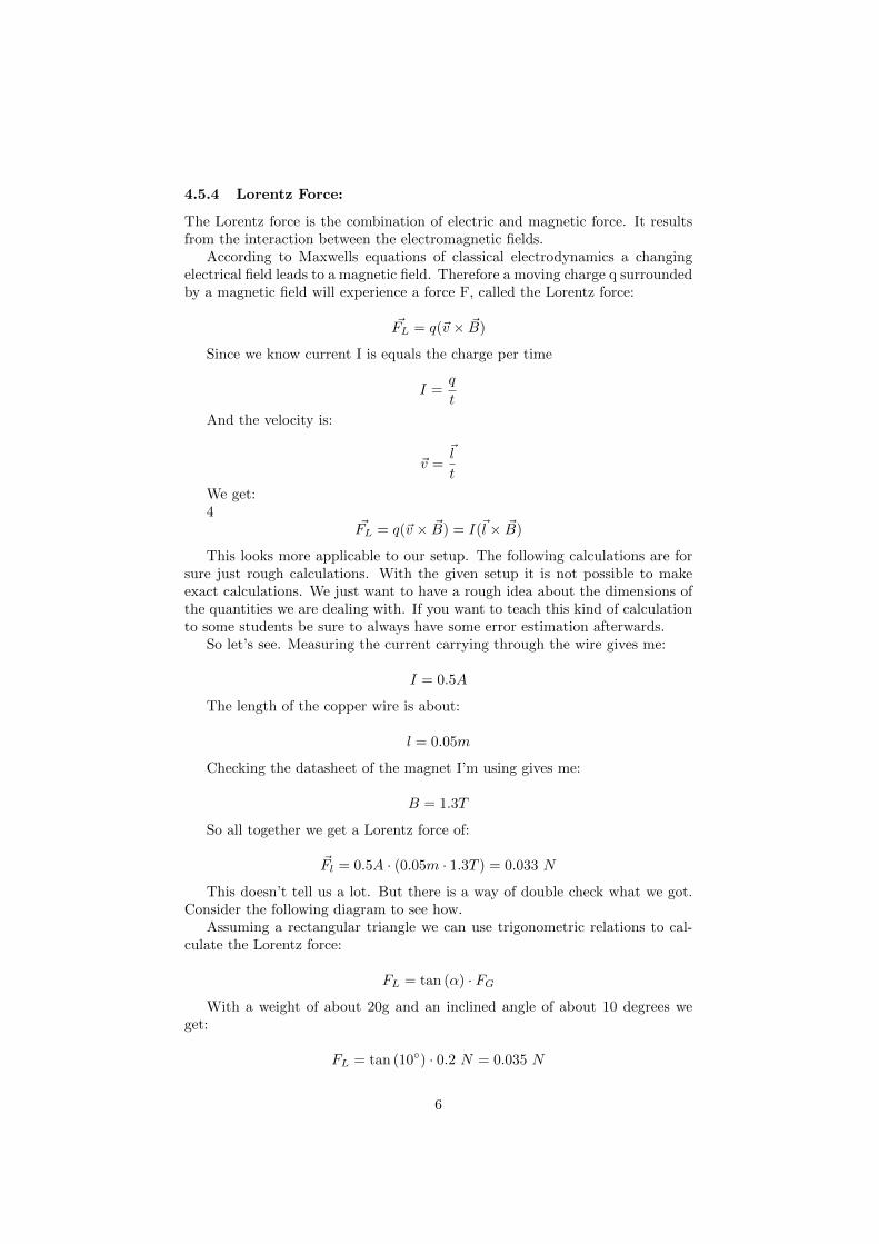
This doesn’t tell us a lot. But there is a way of double check what we got.Consider the following diagram to see how.
Assuming a rectangular triangle we can use trigonometric relations to cal-culate the Lorentz force:
FL = tan (α) · FG
With a weight of about 20g and an inclined angle of about 10 degrees weget:
FL = tan (10◦) · 0.2 N = 0.035 N
6
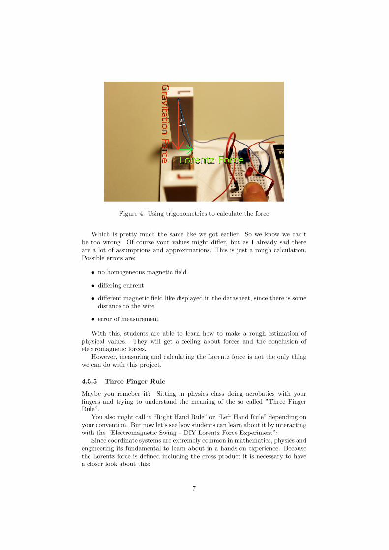
Figure 4: Using trigonometrics to calculate the force
Which is pretty much the same like we got earlier. So we know we can’tbe too wrong. Of course your values might differ, but as I already sad thereare a lot of assumptions and approximations. This is just a rough calculation.Possible errors are:
• no homogeneous magnetic field
• differing current
• different magnetic field like displayed in the datasheet, since there is somedistance to the wire
• error of measurement
With this, students are able to learn how to make a rough estimation ofphysical values. They will get a feeling about forces and the conclusion ofelectromagnetic forces.
However, measuring and calculating the Lorentz force is not the only thingwe can do with this project.
4.5.5 Three Finger Rule
Maybe you remeber it? Sitting in physics class doing acrobatics with yourfingers and trying to understand the meaning of the so called ”Three FingerRule”.
You also might call it “Right Hand Rule” or “Left Hand Rule” depending onyour convention. But now let’s see how students can learn about it by interactingwith the “Electromagnetic Swing – DIY Lorentz Force Experiment”:
Since coordinate systems are extremely common in mathematics, physics andengineering its fundamental to learn about in a hands-on experience. Becausethe Lorentz force is defined including the cross product it is necessary to havea closer look about this:
7
“Given two linearly independent vectors a and b, the cross product, a × b,is a vector that is perpendicular to both a and b and therefore normal to theplane containing them.” (wikipedia)
Therefore the resulting Lorentz force is perpendicular to the direction of thecurrent AND the magnetic field lines. In order to find out about the directionof the Lorentz force we make use of the right-handed coordinates. Using thumb,index and middle finger will help us to figure out the direction of the Lorentzforce.
Consider the following graphic to get an understanding of the “Three FingerRule”:
Figure 5: schematic illustration of the three-finger-rule
As you can see, the choice between whether Left- or Right-hand-rule dependson the direction of the current.
If you are looking for the direction of the electrons flow, which is from minusto plus, you have to take the left hand. Therefore the left hand is used whentalking about the technical current flow, which is from plus to minus.
This is the only thing you should be very cautious about. Since the meaningof the index and middle finger is always the same. So let’s put this straight:
~FL = q · (~v × ~B)
• thumb = points in the direction of the velocity vector v
• index finger = points in the direction of the magnetic field vector B (fromNorth to South)
• middle finger = points in the direction of the cross product F
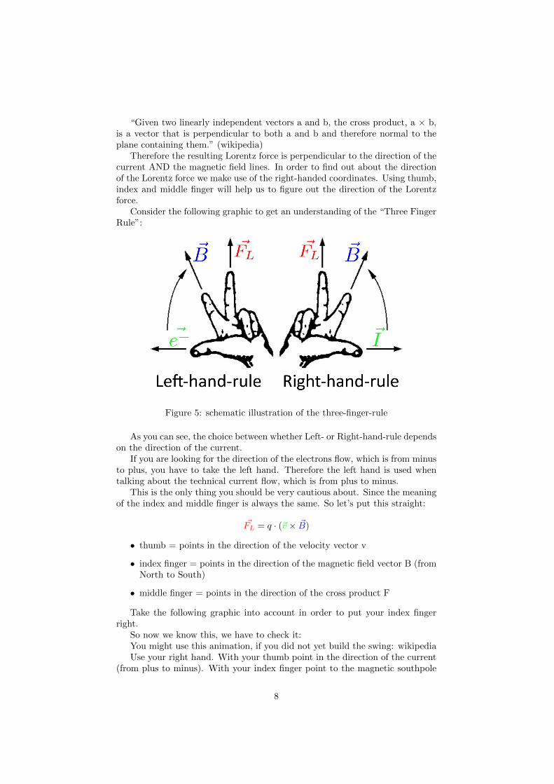
Take the following graphic into account in order to put your index fingerright.
So now we know this, we have to check it:You might use this animation, if you did not yet build the swing: wikipediaUse your right hand. With your thumb point in the direction of the current
(from plus to minus). With your index finger point to the magnetic southpole
8
Figure 6: schematic illustration of the magnetic field lines
(green). The pointing direction of your middle finger now gives you the directionof the Lorentz force. Check it by letting the current flow and observe the move-ment of the Electromagnetic Swing. According to my video (see gallery) youalso can change the polarity of the current or the changing the magnetic polesby simply turning around the magnet (make sure to also change the magnet onthe bottom of the swing, otherwise you will get repulsion).
One nice task for students now is: Where is north and where is south pole?Normally you can’t tell which one is which. Now using this setup and the
three-fingers-rule you are finally able to tell!
4.5.6 Conclusion
I think there are a lot of other things which students can learn with this project.So far, I introduced it some students and they really liked it. I’m looking forwardto improve it and add some more tasks, maybe more electronical stuff for thebreadboard. When I’m done with my university degree I’m for sure will includeit in some physics classes.
4.6 Duration:
So basically teachers have two options:
1. Building the project from scratch together with the students. Includingsoldering, electronic circuit, experimenting, calculating and discussion willlast for about 4 hours of class.
2. Present the finished project: Having one setup and presenting it to theclass. Doing the calculations and the physics and of course some discussionwill last for about 2 hours of class.
4.7 Preparation:
Students should know about:
• the basics of electronics
9

• what vectors are
• optional: either learn trigonometry with this project or know it already
Project material (for the breadboard version):
• 9V battery
• 2 magnets (preferably 1 strong and 1 small)
• about 2x 30cm of wire
• copper wire about 5cm
• mini Breadboard (about 34 x 45mm)
• jumper wire
• potentiometer 1k
• LED (1.85-2.5V at about 20mA current)
• resistor (1kOhm)
Other necessary things:
• wire cutter
• soldering iron
4.8 References:
• most likely every high school physics book will have a section includingthe Lorentz force and the three-finger-rule
• nationalmaglab
• wikipedia
4.9 Rubric & Assessment:
At the end of the project, students should have:
• chosen one suitable 3d part
• printed this part
• set up the circuit
• experienced the effects of the Lorentz force
• an idea about the dimensions of the acting forces
• learned the three-finger-rule
Grading and assessment of the students:
• the overall behavior in this project
10

• did they manage to set up the circuit right?
• did they manage to calculate the Lorentz force (both ways)?
• did they manage to determine the magnetic poles?
Have Fun!
11