Embed Size (px)
Citation preview

ASSEMBLY INSTRUCTIONS
Version 2, Rev B
PCN 061511-1
Top-of-Pole Mount for 12 Modules (TPM12)For Module Types A, B, & C
step-by-step
assembly and installation
A 19-23” 35-44”
B 20-26” 39-50”
C 22-27” 56-63”
ModuleType Width Length
A few words about the product
About these Assembly Instructions
Required Tools
For foundation and pipe size recommendations, on a specific installation pleasecontact us at:
Phone: 800-260-3792
Email: [email protected]
These instructions...
�
�
Are intended to be used by individuals with sufficient technical skills forthe task. Knowledge and use of hand tools, measuring devices and torquevalues is also required.
Include various precautions in the forms of Notes, Cautions, andWarnings. These are to assist in the assembly process and/or to drawattention to the fact that certain assembly steps may be dangerous andcould cause serious personal injury and/or damage to components.Following the step-by-step procedures and these precautions shouldminimize the risk of any personal injury or damage to components whilemaking the installation not only safe but an efficient process.
The TPM12 for module types A, B, & C is designed to mount on 6 inchSCH40/80 galvanized steel pipe (installer supplied).
Pipe size and foundation requirements are based on several factors including thearray surface area, maximum design wind speed, exposure category, soil type,steepest expected tilt angle, and above-ground clearance.
For general foundation and pipe size recommendations, please see our publicationtitled “TPM Pipe and Foundation Recommendations”.
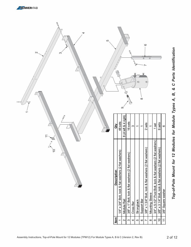
7/16 inch wrench or socket for 1/4 inch module hardware
9/16 inch wrench or socket for 3/8 inch hardware
3/4 inch wrench or socket for 1/2 inch hardware
1-1/8 inch wrench or socket for 3/4 inch Pivot Bolt hardware
Torque wrench
Ratchet wrench
Ratchet extension bar
3 to 6 foot level
Tape Measure
Square
Top-of-Pole Mount for 12 Modules (TPM12) For Module Types A, B, & C
WARNING:Follow theprocedures andprecautions inthese instructionscarefully.
1 of 12Assembly Instructions, Top-of-Pole Mount for 12 Modules (TPM12) For Module Types A, B & C (Version 2, Rev B)
To
p-o
f-P
ole
Mo
un
tfo
r12
Mo
du
les
for
Mo
du
leT
yp
es
A,
B,
&C
Part
sId
en
tifi
cati
on
2 of 12
1
2 3
4
5
67
8
9
10
11
Assembly Instructions, Top-of-Pole Mount for 12 Modules (TPM12) For Module Types A, B & C (Version 2, Rev B)
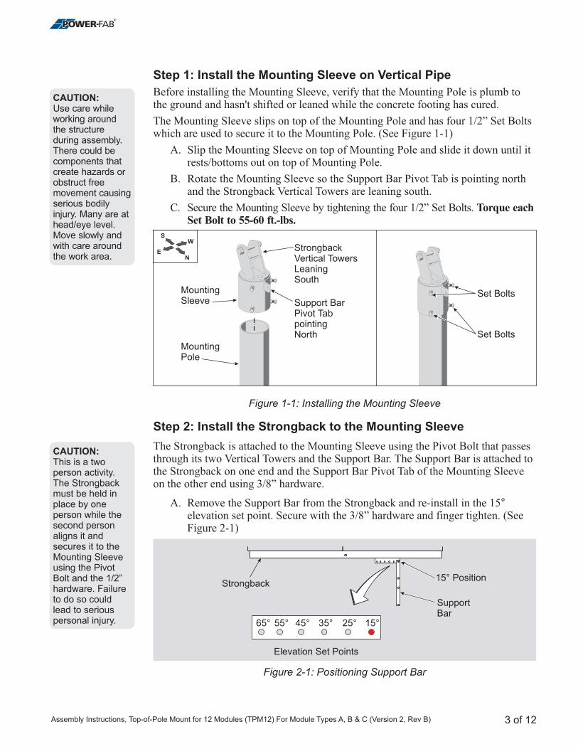
Step 1: Install the Mounting Sleeve on Vertical Pipe
Step 2: Install the Strongback to the Mounting Sleeve
Before installing the Mounting Sleeve, verify that the Mounting Pole is plumb tothe ground and hasn't shifted or leaned while the concrete footing has cured.
The Mounting Sleeve slips on top of the Mounting Pole and has four 1/2” Set Boltswhich are used to secure it to the Mounting Pole. (See Figure 1-1)
A. Slip the Mounting Sleeve on top of Mounting Pole and slide it down until itrests/bottoms out on top of Mounting Pole.
B. Rotate the Mounting Sleeve so the Support Bar Pivot Tab is pointing northand the Strongback Vertical Towers are leaning south.
C. Secure the Mounting Sleeve by tightening the four 1/2” Set Bolts.
The Strongback is attached to the Mounting Sleeve using the Pivot Bolt that passesthrough its two Vertical Towers and the Support Bar. The Support Bar is attached tothe Strongback on one end and the Support Bar Pivot Tab of the Mounting Sleeveon the other end using 3/8” hardware.
A. Remove the Support Bar from the Strongback and re-install in the 15elevation set point. Secure with the hardware and finger tighten. (SeeFigure 2-1)
Torque eachSet Bolt to 55-60 ft.-lbs.
°3/8”
Figure 1-1: Installing the Mounting Sleeve
Figure 2-1: Positioning Support Bar
CAUTION:Use care whileworking aroundthe structureduring assembly.There could becomponents thatcreate hazards orobstruct freemovement causingserious bodilyinjury. Many are athead/eye level.Move slowly andwith care aroundthe work area.
CAUTION:This is a twoperson activity.The Strongbackmust be held inplace by oneperson while thesecond personaligns it andsecures it to theMounting Sleeveusing the PivotBolt and the 1/2”hardware. Failureto do so couldlead to seriouspersonal injury.
3 of 12
Elevation Set Points
Strongback
SupportBar
65° 55° 45° 35° 25° 15°
15° Position
NE
WS
MountingSleeve
StrongbackVertical TowersLeaningSouth
Support BarPivot TabpointingNorth
MountingPole
Set Bolts
Set Bolts
Assembly Instructions, Top-of-Pole Mount for 12 Modules (TPM12) For Module Types A, B & C (Version 2, Rev B)
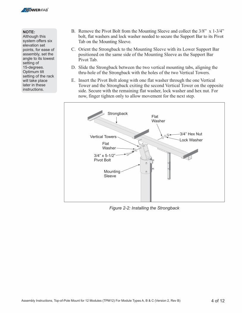
B. Remove the Pivot Bolt from the Mounting Sleeve and collect the x 1-3/4”bolt, flat washers and lock washer needed to secure the Support Bar to its PivotTab on the Mounting Sleeve.
C. Orient the Strongback to the Mounting Sleeve with its Lower Support Barpositioned on the same side of the Mounting Sleeve as the Support BarPivot Tab.
D. Slide the Strongback between the two vertical mounting tabs, aligning thethru-hole of the Strongback with the holes of the two Vertical Towers.
E. Insert the Pivot Bolt along with one flat washer through the one VerticalTower and the Strongback exiting the second Vertical Tower on the oppositeside. Secure with the remaining flat washer, lock washer and hex nut. Fornow, finger tighten only to allow movement for the next step.
3/8”
Figure 2-2: Installing the Strongback
NOTE:Although thissystem offers sixelevation setpoints, for ease ofassembly, set theangle to its lowestsetting of15-degrees.Optimum tiltsetting of the rackwill take placelater in theseinstructions.
4 of 12
Strongback
Bolt3/4” x 5-1/2”Pivot
FlatWasher
Vertical Towers
FlatWasher
Lock Washer
3/4” Hex Nut
MountingSleeve
Assembly Instructions, Top-of-Pole Mount for 12 Modules (TPM12) For Module Types A, B & C (Version 2, Rev B)
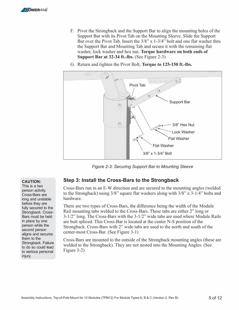
F. Pivot the Strongback and the Support Bar to align the mounting holes of theSupport Bar with its Pivot Tab on the Mounting Sleeve. Slide the SupportBar over the Pivot Tab. Insert the 3/8” x 1-3/4” bolt and one flat washer thruthe Support Bar and Mounting Tab and secure it with the remaining flatwasher, lock washer and hex nut.
(See Figure 2-3)
G. Return and tighten
Cross-Bars run in an E-W direction and are secured to the mounting angles (using 3/8” square flat washers along with 3/8” x 3-1/4” bolts and
hardware.
There are two types of Cross-Bars, the difference being the width of the ModuleRail mounting tabs welded to the Cross-Bars. These tabs are either 2” long or3-1/2” long. The Cross-Bars with the 3-1/2” wide tabs are used where Module Railsare butt spliced. This Cross-Bar is located at the center N-S position of theStrongback. Cross-Bars with 2” wide tabs are used to the north and south of thecenter-most Cross-Bar.
Cross-Bars are mounted to the outside of the Strongback mounting angles (these arewelded to the Strongback). They are not nested into the Mounting Angles. (SeeFigure 3-2)
Torque hardware on both ends ofSupport Bar at 32-34 ft.-lbs.
Torque to 125-150 ft.-lbs.the Pivot Bolt,
weldedto the Strongback)
(See Figure 3-1)
Step 3: Install the Cross-Bars to the Strongback
Figure 2-3: Securing Support Bar to Mounting Sleeve
CAUTION:This is a twoperson activity.Cross-Bars arelong and unstablebefore they arefully secured to theStrongback. Cross-Bars must be heldin place by oneperson while thesecond personaligns and securesthem to theStrongback. Failureto do so could leadto serious personalinjury.
5 of 12
3/8” Boltx 1-3/4”
Flat Washer
Pivot Tab
Flat Washer
Lock Washer
Support Bar
3/8” Hex Nut
Assembly Instructions, Top-of-Pole Mount for 12 Modules (TPM12) For Module Types A, B & C (Version 2, Rev B)
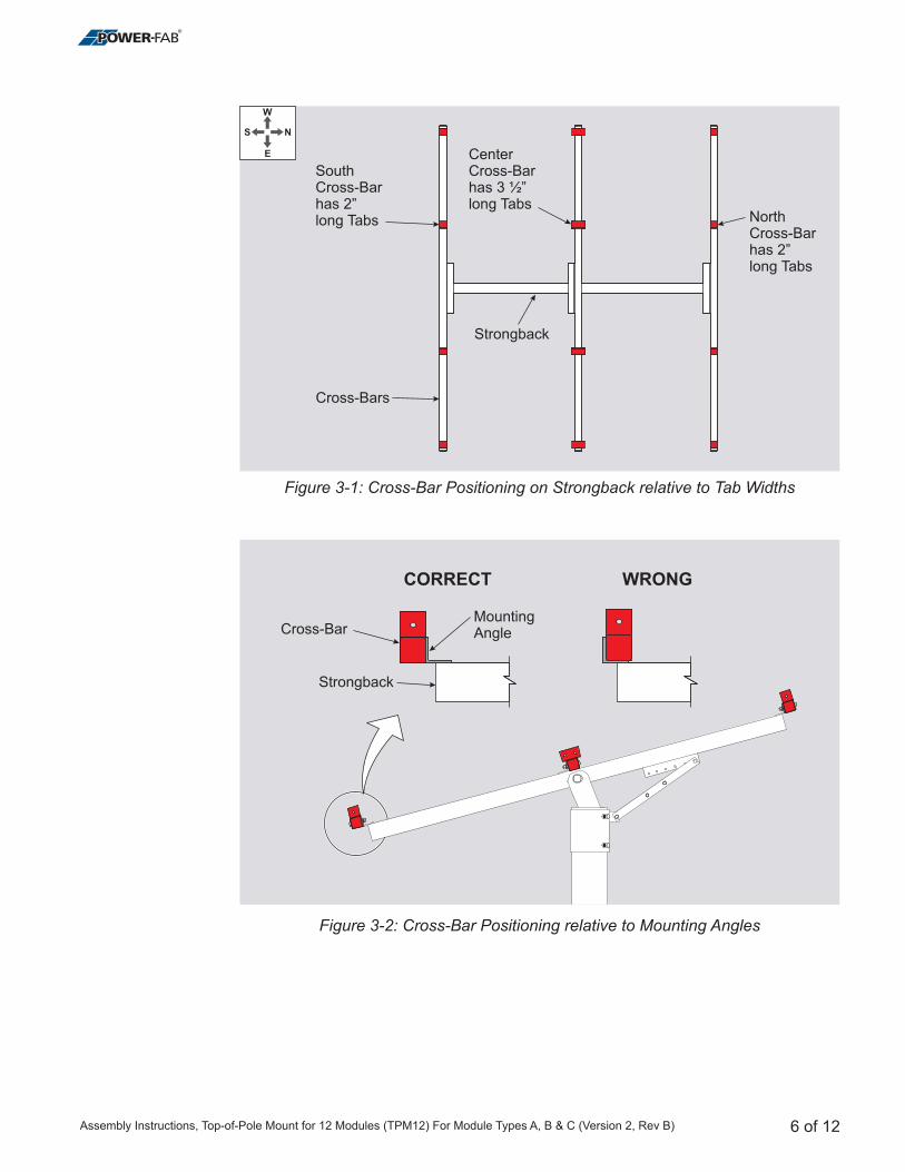
Strongback
Cross-BarMountingAngle
CORRECT WRONG
Figure 3-1: Cross-Bar Positioning on Strongback relative to Tab Widths
Figure 3-2: Cross-Bar Positioning relative to Mounting Angles
N
E
W
S
Strongback
Cross-Bars
CenterCross-Barhas 3 ½”long Tabs
SouthCross-Barhas 2”long Tabs North
Cross-Barhas 2”long Tabs
6 of 12Assembly Instructions, Top-of-Pole Mount for 12 Modules (TPM12) For Module Types A, B & C (Version 2, Rev B)
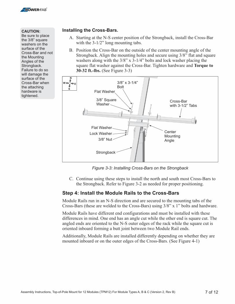
Installing the Cross-Bars.
A. Starting at the N-S center position of the Strongback, install the Cross-Barwith the 3-1/2” long mounting tabs.
B. Position the Cross-Bar on the outside of the center mounting angle of theStrongback. Align the mounting holes and secure using 3/8” flat and squarewashers along with the 3/8” x 3-1/4” bolts and lock washer placing thesquare flat washer against the Cross-Bar. Tighten hardware and
(See Figure 3-3)
C. Continue using these steps to install the north and south most Cross-Bars tothe Strongback. Refer to Figure 3-2 as needed for proper positioning.
Module Rails run in an N-S direction and are secured to the mounting tabs of theCross-Bars (these are welded to the Cross-Bars) using 3/8” x 1” bolts and hardware.
Module Rails have different end configurations and must be installed with thesedifferences in mind. One end has an angle cut while the other end is square cut. Theangled ends are oriented to the N-S outer edges of the rack while the square cut isoriented inboard forming a butt joint between two Module Rail ends.
Additionally, Module Rails are installed differently depending on whether they aremounted inboard or on the outer edges of the Cross-Bars. (See Figure 4-1)
Torque to30-32 ft.-lbs.
Step 4: Install the Module Rails to the Cross-Bars
CAUTION:Be sure to placethe 3/8” squarewashers on thesurface of theCross-Bar and notthe MountingAngles of theStrongback.Failure to do sowill damage thesurface of theCross-Bar whenthe attachinghardware istightened.
Figure 3-3: Installing Cross-Bars on the Strongback
7 of 12
N
EW
S
Strongback
Cross-Barwith 3-1/2” Tabs
CenterMountingAngle
3/8” SquareWasher
Flat Washer
Lock Washer
Flat Washer
3/8” Nut
3/8” x 3-1/4”Bolt
Assembly Instructions, Top-of-Pole Mount for 12 Modules (TPM12) For Module Types A, B & C (Version 2, Rev B)
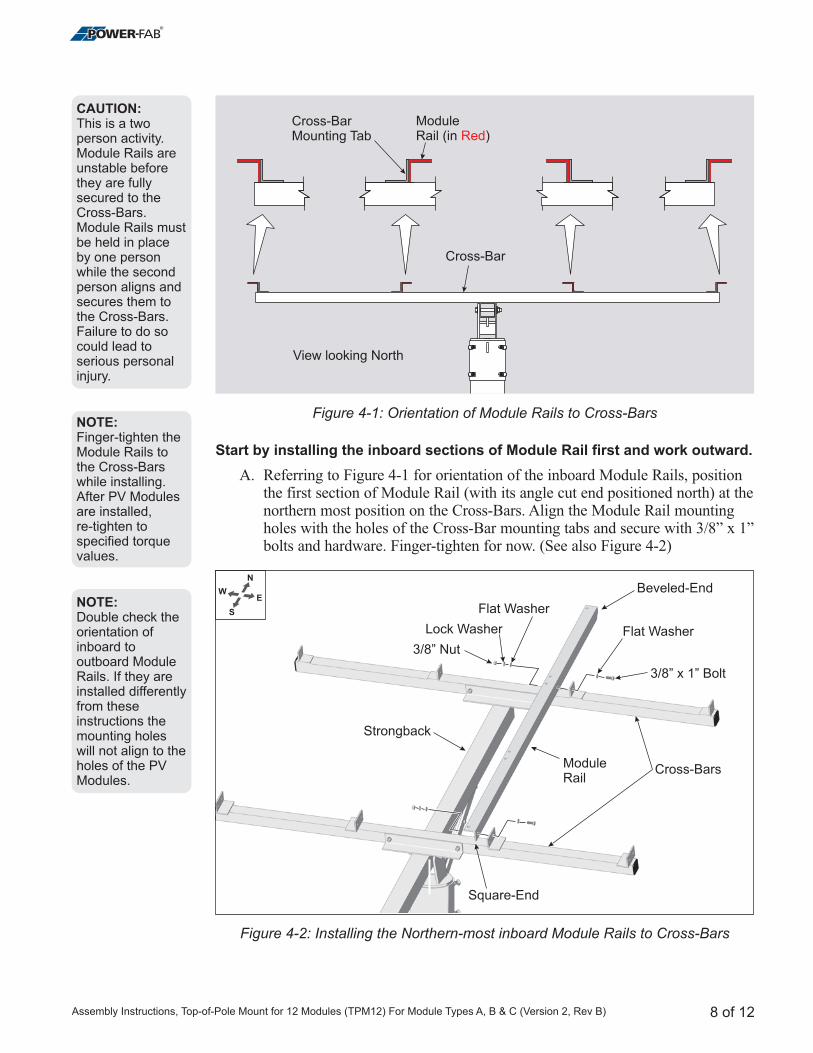
Start by installing the inboard sections of Module Rail first and work outward.
A. Referring to Figure 4-1 for orientation of the inboard Module Rails, positionthe first section of Module Rail (with its angle cut end positioned north) at thenorthern most position on the Cross-Bars. Align the Module Rail mountingholes with the holes of the Cross-Bar mounting tabs and secure with 3/8” x 1”bolts and hardware. Finger-tighten for now. (See also Figure 4-2)
Cross-Bar
ModuleRail (in )Red
View looking North
Cross-BarMounting Tab
Figure 4-1: Orientation of Module Rails to Cross-Bars
Figure 4-2: Installing the Northern-most inboard Module Rails to Cross-Bars
NOTE:Finger-tighten theModule Rails tothe Cross-Barswhile installing.After PV Modulesare installed,re-tighten tospecified torquevalues.
NOTE:Double check theorientation ofinboard tooutboard ModuleRails. If they areinstalled differentlyfrom theseinstructions themounting holeswill not align to theholes of the PVModules.
CAUTION:This is a twoperson activity.Module Rails areunstable beforethey are fullysecured to theCross-Bars.Module Rails mustbe held in placeby one personwhile the secondperson aligns andsecures them tothe Cross-Bars.Failure to do socould lead toserious personalinjury.
8 of 12
ModuleRail
Cross-Bars
Strongback
Beveled-End
Square-End
3/8” x 1” Bolt
Lock Washer
Flat Washer
Flat Washer
3/8” Nut
N
EW
S
Assembly Instructions, Top-of-Pole Mount for 12 Modules (TPM12) For Module Types A, B & C (Version 2, Rev B)
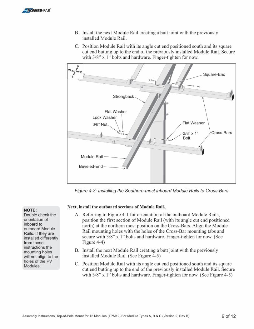
B. Install the next Module Rail creating a butt joint with the previouslyinstalled Module Rail.
C. Position Module Rail with its angle cut end positioned south and its squarecut end butting up to the end of the previously installed Module Rail. Securewith 3/8” x 1” bolts and hardware. Finger-tighten for now.
A. Referring to Figure 4-1 for orientation of the outboard Module Rails,position the first section of Module Rail (with its angle cut end positionednorth) at the northern most position on the Cross-Bars. Align the ModuleRail mounting holes with the holes of the Cross-Bar mounting tabs andsecure with 3/8” x 1” bolts and hardware. Finger-tighten for now. (SeeFigure 4-4)
B. Install the next Module Rail creating a butt joint with the previouslyinstalled Module Rail.
C. Position Module Rail with its angle cut end positioned south and its squarecut end butting up to the end of the previously installed Module Rail. Securewith 3/8” x 1” bolts and hardware. Finger-tighten for now. (See Figure 4-5)
Next, install the outboard sections of Module Rail..
(See Figure 4-5)
Figure 4-3: Installing the Southern-most inboard Module Rails to Cross-Bars
NOTE:Double check theorientation ofinboard tooutboard ModuleRails. If they areinstalled differentlyfrom theseinstructions themounting holeswill not align to theholes of the PVModules.
9 of 12
N
EW
S
Strongback
Module Rail
Cross-Bars
Square-End
Beveled-End
3/8” x 1”Bolt
Lock Washer
Flat Washer
Flat Washer3/8” Nut
Assembly Instructions, Top-of-Pole Mount for 12 Modules (TPM12) For Module Types A, B & C (Version 2, Rev B)

Figure 4-4: Installing the Northern-most outboard Module Rails to Cross-Bars
Figure 4-5: Installing the Southern-most outboard Module Rails to Cross-Bars
10 of 12
N
EW
S
Module Rail
Cross-Bar
Cross-Bar
Square-End
Beveled-End
3/8” x 1”Bolt
Lock Washer
Flat Washer
FlatWasher
3/8” Nut
N
EW
S
Module Rail
Cross-Bar
Cross-Bar
Strongback
Beveled-End
Square-End
3/8” x 1”Bolt
Lock Washer
Flat Washer
FlatWasher
3/8” Nut
Assembly Instructions, Top-of-Pole Mount for 12 Modules (TPM12) For Module Types A, B & C (Version 2, Rev B)
Step 5: Installing PV Modules to Module Rails
Step 6: Now return and tighten mounting hardware.
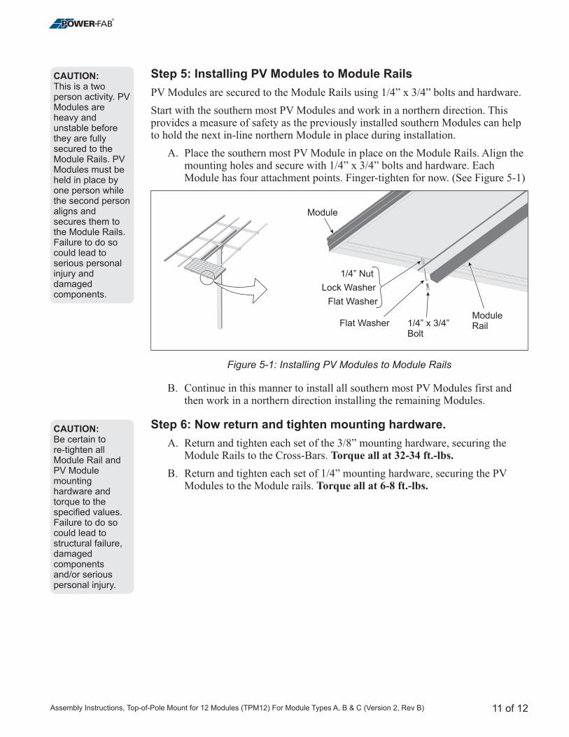
PV Modules are secured to the Module Rails using 1/4” x 3/4” bolts and hardware.
Start with the southern most PV Modules and work in a northern direction. Thisprovides a measure of safety as the previously installed southern Modules can helpto hold the next in-line northern Module in place during installation.
A. Place the southern most PV Module in place on the Module Rails. Align themounting holes and secure with 1/4” x 3/4” bolts and hardware. EachModule has four attachment points. Finger-tighten for now. (See Figure 5-1)
B. Continue in this manner to install all southern most PV Modules first andthen work in a northern direction installing the remaining Modules.
A. Return and tighten each set of the 3/8” mounting hardware, securing theModule Rails to the Cross-Bars.
B. Return and tighten each set of 1/4” mounting hardware, securing the PVModules to the Module rails.
Torque all at 32-34 ft.-lbs.
Torque all at 6-8 ft.-lbs.
CAUTION:This is a twoperson activity. PVModules areheavy andunstable beforethey are fullysecured to theModule Rails. PVModules must beheld in place byone person whilethe second personaligns andsecures them tothe Module Rails.Failure to do socould lead toserious personalinjury anddamagedcomponents.
CAUTION:Be certain tore-tighten allModule Rail andPV Modulemountinghardware andtorque to thespecified values.Failure to do socould lead tostructural failure,damagedcomponentsand/or seriouspersonal injury.
Figure 5-1: Installing PV Modules to Module Rails
11 of 12
1/4” x 3/4”Bolt
Lock Washer
Flat Washer
Flat Washer
1/4” Nut
Module
ModuleRail
Assembly Instructions, Top-of-Pole Mount for 12 Modules (TPM12) For Module Types A, B & C (Version 2, Rev B)

Step 7: Adjust the Tilt Angle of the Rack
To adjust the tilt angle, loosen the Pivot Bolt hardware and removing the SupportArm upper hardware attaching the Support Arm to the Strongback. Use great care inthis procedure as it can be dangerous if the procedure is not done as described anddone with a minimum of two people.
A. While one person holds the south edge of rack, the other loosens the PivotBolt and removes the upper 3/8” hardware attaching the Support Bar to theStrongback. (See Figure 7-1)
B. Tilt the rack to the desired elevation angle (15°, 25°, 35°, 45°, 55°, or 65°)and re-attach the Support Bar to the Strongback placing the 3/8” hardware inthe appropriate hole matching the desired elevation.(See Figure 7-2)
C. Re-Tighten the Pivot Bolt.
Torque to 32-34 ft.-lbs.
Torque to 125-150 ft.-lbs.
CAUTION:Do not attempt toremove the PivotBolt during tiltadjustments!Removal couldlead to seriouspersonal injury ordeath. Adjustmentsare made with thePivot Bolthardware loosenedbut in place.
CAUTION:This is a twoperson activity. Asthe Pivot Bolt isloosened and theSupport Barhardware isremoved, the rackis heavy andunstable. The rackmust be held inplace by oneperson while thesecond personloosens andremoves thehardware and thenre-installs/tightensthe hardware backin place. Failure todo so could leadto seriouspersonal injuryand damagedcomponents.
Figure 7-1: Preparing to Adjust the Tilt Angle
Figure 7-2: Setting the Tilt Angle
12 of 12
LoosenPivot Bolt
RemoveSupport ArmHardware(upper hardware only)
Elevation Set Points
Strongback
SupportBar
65° 55° 45° 35° 25° 15°
Assembly Instructions, Top-of-Pole Mount for 12 Modules (TPM12) For Module Types A, B & C (Version 2, Rev B)

4000-B Vassar Drive NE
Albuquerque, New Mexico 87107
USA
Telephone: 800.260.3792
Fax: 505.889.3548
Web Site: www.DPWSolar.com
E-mail: [email protected]
© 2011 Preformed Line Products
PCN 061511-1
Version 2, Rev B