Embed Size (px)
Citation preview
ASSOCIATED
Federazione delle Associazioni Nazionalidell'Industria Meccanica Varia ed Affine
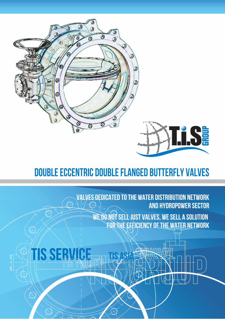
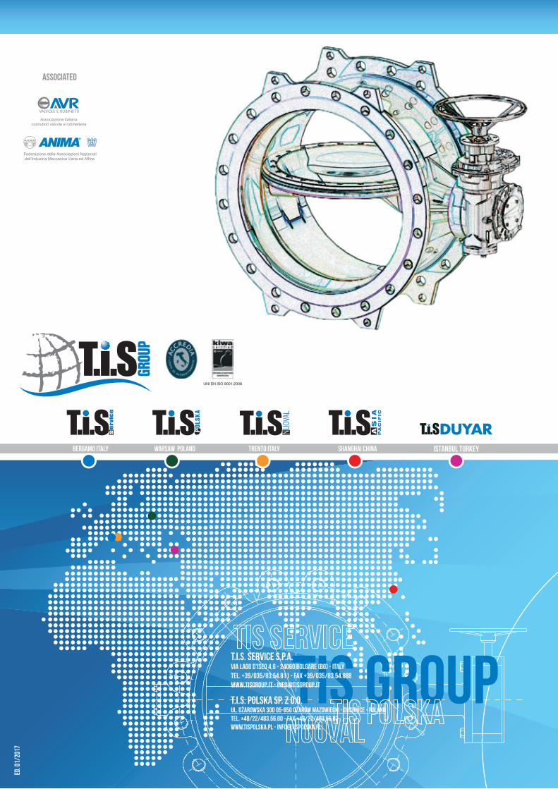
DOUBLE ECCENTRIC DOUBLE FLANGED BUTTERFLY VALVES
TIS GRoupTIS asia
T.I.S. Service S.p.A.Via Lago d’Iseo 4,6 - 24060 Bolgare (BG) - Italy
ED. 0
1/20
17
Tel. +39/035/83.54.811 - Fax +39/035/83.54.888www.TISGROUP.IT - [email protected]
VALVES DEDICATED TO THE WATER DISTRIBUTION NETWORKAND HYDROPOWER SECTOR
WE DO NOT SELL JUST VALVES, WE SELL A SOLUTION FOR THE EFFICIENCY OF THE WATER NETWORK
ISTANBUL TURKEY
T.I.S. SERVICE S.p.A., is a leading international company specializing in the production and sale of equipment for water networks services and for hydroelectric power plants. One of its core products are safety valves.
Thanks to its partners, the company is able to produce a wide range of high technology valves and fittings, both in cast iron and plastic; butterfly valves, gate valves, air release valves, automatic control valves, plunger flow control valves and dismantling joints. These products can be controlled by electric motors or pneumatic actuators.
The T.i.S. system guarantees a complete solution package: from individual equipment sup-plies to engineering consultations on the more complex problems of water systems. The company’s main activities are: supply of hydraulic equipment, automation, hydraulic net-work modelling and model calibration, leak detection, controlled pressure management, energy efficiency, white certificate management.
T.i.S. Service offers customers a personalized service, from the equipment selection stage right through to after-sales support.
All T.i.S. companies are certified ISO 9001. The company has held the prestigious Group certification since 2011.
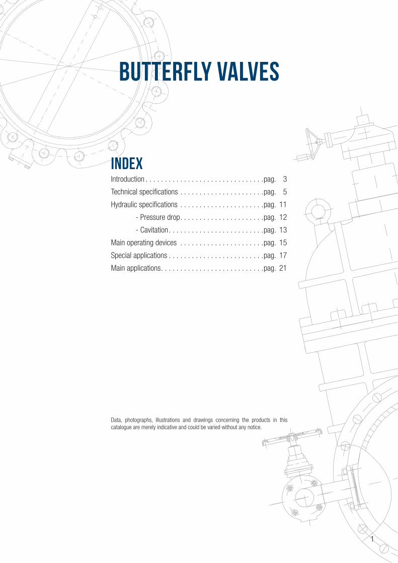
BUTTERFLY VALVES
INDEXIntroduction . . . . . . . . . . . . . . . . . . . . . . . . . . . . . . .pag. 3
Technical specifications . . . . . . . . . . . . . . . . . . . . . .pag. 5
Hydraulic specifications . . . . . . . . . . . . . . . . . . . . . .pag. 11
- Pressure drop . . . . . . . . . . . . . . . . . . . . . .pag. 12
- Cavitation . . . . . . . . . . . . . . . . . . . . . . . . .pag. 13
Main operating devices . . . . . . . . . . . . . . . . . . . . . .pag. 15
Special applications . . . . . . . . . . . . . . . . . . . . . . . . .pag. 17
Main applications . . . . . . . . . . . . . . . . . . . . . . . . . . .pag. 21
Data, photographs, illustrations and drawings concerning the products in this catalogue are merely indicative and could be varied without any notice.
1
INTRODUCTION
INTRODUCTION
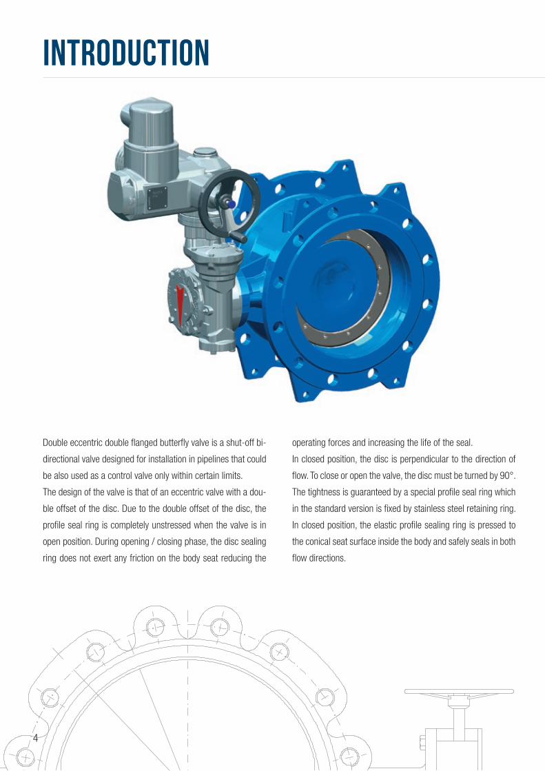
Double eccentric double flanged butterfly valve is a shut-off bi-
directional valve designed for installation in pipelines that could
be also used as a control valve only within certain limits.
The design of the valve is that of an eccentric valve with a dou-
ble offset of the disc. Due to the double offset of the disc, the
profile seal ring is completely unstressed when the valve is in
open position. During opening / closing phase, the disc sealing
ring does not exert any friction on the body seat reducing the
operating forces and increasing the life of the seal.
In closed position, the disc is perpendicular to the direction of
flow. To close or open the valve, the disc must be turned by 90°.
The tightness is guaranteed by a special profile seal ring which
in the standard version is fixed by stainless steel retaining ring.
In closed position, the elastic profile sealing ring is pressed to
the conical seat surface inside the body and safely seals in both
flow directions.
4
TECHNICAL SPECIFICATIONS
TECHNICAL SPECIFICATIONS
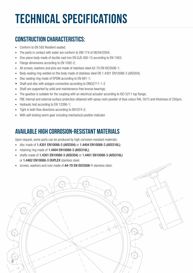
CONSTRUCTION CHARACTERISTICS:• Conform to EN 593 Resilient seated;
• The parts in contact with water are conform to DM 174 of 06/04/2004;
• One-piece body made of ductile cast iron EN GJS 400-15 according to EN 1563;
• Flange dimensions according to EN 1092-2;
• All screws, washers and pins are made of stainless steel A2-70 EN ISO3506-1;
• Body sealing ring welded on the body made of stainless steel EN 1.4301 EN10088-3 (AISI304);
• Disc sealing ring made of EPDM according to EN 681-1;
• Shaft and disc with polygon connection according to DIN32711-1-2
• Shaft are supported by solid and maintenance-free bronze bearings;
• The gearbox is suitable for the coupling with an electrical actuator according to ISO 5211 top flange;
• FBE internal and external surface protection obtained with epoxy resin powder of blue colour RAL 5015 and thickness of 250μm;
• Hydraulic test according to EN 12266-1;
• Tight in both flow directions according to EN1074-2;
• With self-locking worm gear including mechanical position indicator.
AVAILABLE HIGH CORROSION-RESISTANT MATERIALSUpon request, some parts can be produced by high corrosion-resistant materials:
• disc made of 1.4301 EN10088-3 (AISI304) or 1.4404 EN10088-3 (AISI316L); • retaining ring made of 1.4404 EN10088-3 (AISI316L);• shafts made of 1.4301 EN10088-3 (AISI304) or 1.4401 EN10088-3 (AISI316L)
or 1.4462 EN10088-3 DUPLEX stainless steel;
• screws, washers and nuts made of A4-70 EN ISO3506-1 stainless steel;
6

STANDARD VALVE MATERIALS
ITEM DESCRIPTION MATERIAL NOTE
1 BODY DUCTILE IRON EN-GJS 400-15 FBE COATED
2 DISC DUCTILE IRON EN-GJS 400-15 FBE COATED
3 RETAINING RING STAINLESS STEEL AISI304 (EN1.4301)
4 DRIVEN SHAFT STAINLESS STEEL AISI420 (EN1.4028)
5 SHAFT (Free end) STAINLESS STEEL AISI420 (EN1.4028)
6 BEARING BUSH ALUMINUM-BRONZE
7 SEALING BUSH ALUMINUM-BRONZE
8 SEALING BUSH COVER STAINLESS STEEL
9 SEALING BUSH FLANGE STAINLESS STEEL
10 SPACER BUSH STAINLESS STEEL
12 PROFILE SEAL EPDM RUBBER
13 O-RING NBR RUBBER
14 O-RING NBR RUBBER
15 O-RING NBR RUBBER
16 PIN STAINLESS STEEL A2-70
17 GRUB SCREW STAINLESS STEEL A2-70
18 RETAINING RING SCREW STAINLESS STEEL A2-70
19 GRUB SCREW STAINLESS STEEL A2-70
20 COVER SCREW AND WASHER STAINLESS STEEL A2-70
21 PARALLEL KEY STEEL
22 GEAR BOX ACCORDING TO SUPPLIER SPECIFICATION
EYE BOLTS AVAILABLE ON REQUEST
7

PN10DN G K D n-ød b L e1 e2 h w (kg)
200 266 295 340 8-23 20 230 185 308 179 54
250 319 350 395 12-23 22 250 209 332 209 68
300 370 400 445 12-23 24.5 270 240 278 234 103
350 429 460 505 16-23 24.5 290 263 401 262 125
400 480 515 565 16-28 24.5 310 297,5 460 287 178
450 530 565 615 20-28 25.5 330 324,5 522 311 219
500 582 620 670 20-28 26.5 350 348 545 341 263
600 682 725 780 20-31 30 390 422 615 399 373
700 794 840 895 24-31 32.5 430 482 720 458 502
800 901 950 1015 24-34 35 470 541 817 518 729
900 1001 1050 1115 28-34 37.5 510 613 873 568 924
1000 1112 1160 1230 28-37 40 550 675 921 623 1493
1200 1328 1380 1455 32-41 45 630 800 1133 736 2224
1400 1530 1590 1675 36-44 46 710 985 1302 845 2935
1600 1750 1820 1915 40-50 49 790 1115 1427 970 3785
1800 1950 2020 2115 44-50 52 870 1245.5 1714 1070 5356
2000 2150 2230 2325 48-50 55 950 1494.5 1819 1182.5 7168
DIMENSIONS AND WEIGHT
8
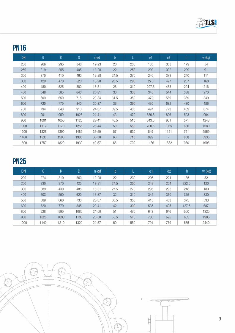
PN16
PN25
DN G K D n-ød b L e1 e2 h w (kg)
200 266 295 340 12-23 20 230 185 308 179 54
250 319 355 405 12-28 22 250 209 332 209 91
300 370 410 460 12-28 24.5 270 240 378 240 111
350 429 470 520 16-28 26.5 290 275 427 267 168
400 480 525 580 16-31 28 310 297,5 485 294 216
450 548 585 640 20-31 30 330 345 544 338 270
500 609 650 715 20-34 31.5 350 372 569 369 349
600 720 770 840 20-37 36 390 430 682 430 486
700 794 840 910 24-37 39.5 430 497 772 469 674
800 901 950 1025 24-41 43 470 580,5 826 523 904
900 1001 1050 1125 28-41 46.5 510 643,5 951 571 1243
1000 1112 1170 1255 28-44 50 550 700,5 1035 636 1580
1200 1328 1390 1485 32-50 57 630 849 1151 751 2569
1400 1530 1590 1985 36-50 60 710 992 - 858 3335
1600 1750 1820 1930 40-57 65 790 1136 1582 980 4905
DN G K D n-ød b L e1 e2 h w (kg)
200 274 310 360 12-28 22 230 206 221 185 82
250 330 370 425 12-31 24.5 250 248 254 222.5 120
300 389 430 485 16-31 27.5 270 295 298 248 180
400 503 550 620 16-37 32 310 345 370 315 330
500 609 660 730 20-37 36.5 350 415 453 375 533
600 720 770 845 20-41 42 390 535 495 427.5 687
800 928 990 1085 24-50 51 470 643 646 550 1325
900 1028 1090 1185 28-50 55.5 510 708 695 605 1985
1000 1140 1210 1320 24-57 60 550 791 779 665 2440
9

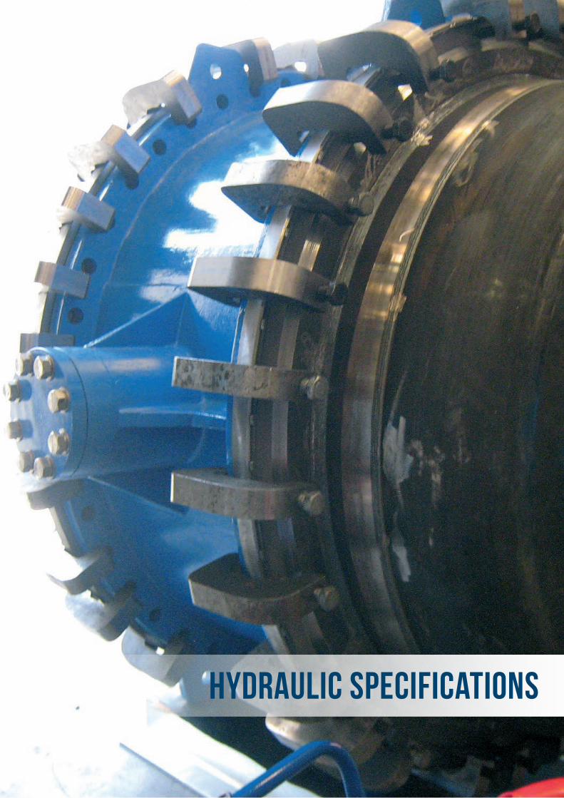
HYDRAULIC SPECIFICATIONS
HYDRAULIC SPECIFICATIONS
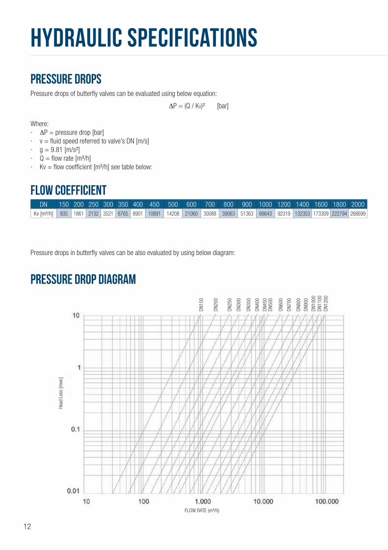
PRESSURE DROPSPressure drops of butterfly valves can be evaluated using below equation:
ΔP = (Q / KV)² [bar]
Where:· ΔP = pressure drop [bar]· v = fluid speed referred to valve’s DN [m/s]· g = 9.81 [m/s²]· Q = flow rate [m³/h]· Kv = flow coefficient [m³/h] see table below:
FLOW COEFFICIENT
PRESSURE DROP DIAGRAM
DN 150 200 250 300 350 400 450 500 600 700 800 900 1000 1200 1400 1600 1800 2000Kv [m³/h] 935 1861 2132 3521 6765 8901 10891 14208 21060 30088 39063 51363 66643 92319 132353 173309 222794 268699
Pressure drops in butterfly valves can be also evaluated by using below diagram:
Head
Les
s [m
wc]
FLOW RATE (m³/h)
DN15
0
DN20
0
DN25
0
DN30
0
DN35
0
DN40
0
DN45
0DN
500
DN60
0
DN70
0
DN80
0
DN90
0
DN10
00DN
1100
DN12
00
12
CAVITATIONButterfly valves are mainly used to shut off the flow. If a butterfly valve is used to control the flow, the operational limits of the maximum flow velocity as well as the cavitation must be observed.
Cavitation number could be evaluated within below equation:
σ = Pout / (ΔP + v²/2g)Where:· ΔP = pressure drop [mhw]· Pout = valve outlet pressure· v = fluid velocity referred to valve’s DN [m/s]· g = 9.81 m/s²
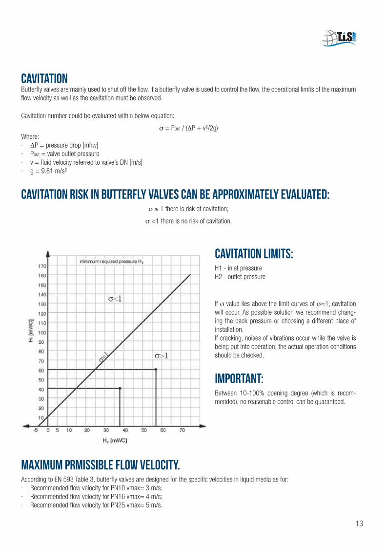
Cavitation risk in butterfly valves can be approximately evaluated:σ ≥ 1 there is risk of cavitation;
σ <1 there is no risk of cavitation.
Cavitation limits:H1 - inlet pressureH2 - outlet pressure
If σ value lies above the limit curves of σ=1, cavitation will occur. As possible solution we recommend chang-ing the back pressure or choosing a different place of installation.If cracking, noises of vibrations occur while the valve is being put into operation; the actual operation conditions should be checked.
IMPORTANT:Between 10-100% opening degree (which is recom-mended), no reasonable control can be guaranteed.
MAXIMUM PRMISSIBLE FLOW VELOCITY.According to EN 593 Table 3, butterfly valves are designed for the specific velocities in liquid media as for:· Recommended flow velocity for PN10 vmax= 3 m/s;· Recommended flow velocity for PN16 vmax= 4 m/s;· Recommended flow velocity for PN25 vmax= 5 m/s.
13

MAIN OPERATING DEVICES

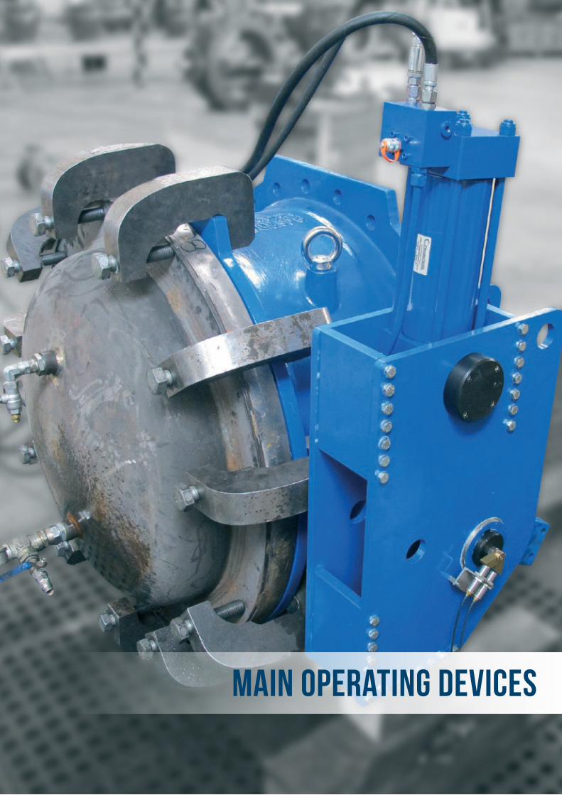
MAIN OPERATING DEVICES
MAINVALVE
ELECTRIC ACTUATORWORM GEAR BOXESAND HAND WHEEL
HYDRAULIC CYLINDER WITHDOUBLE ACTING
HYDRAULIC CYLINDERAND COUNTERWEIGHT
PNEUMATIC ACTUATOR
16
SPECIAL APPLICATIONS
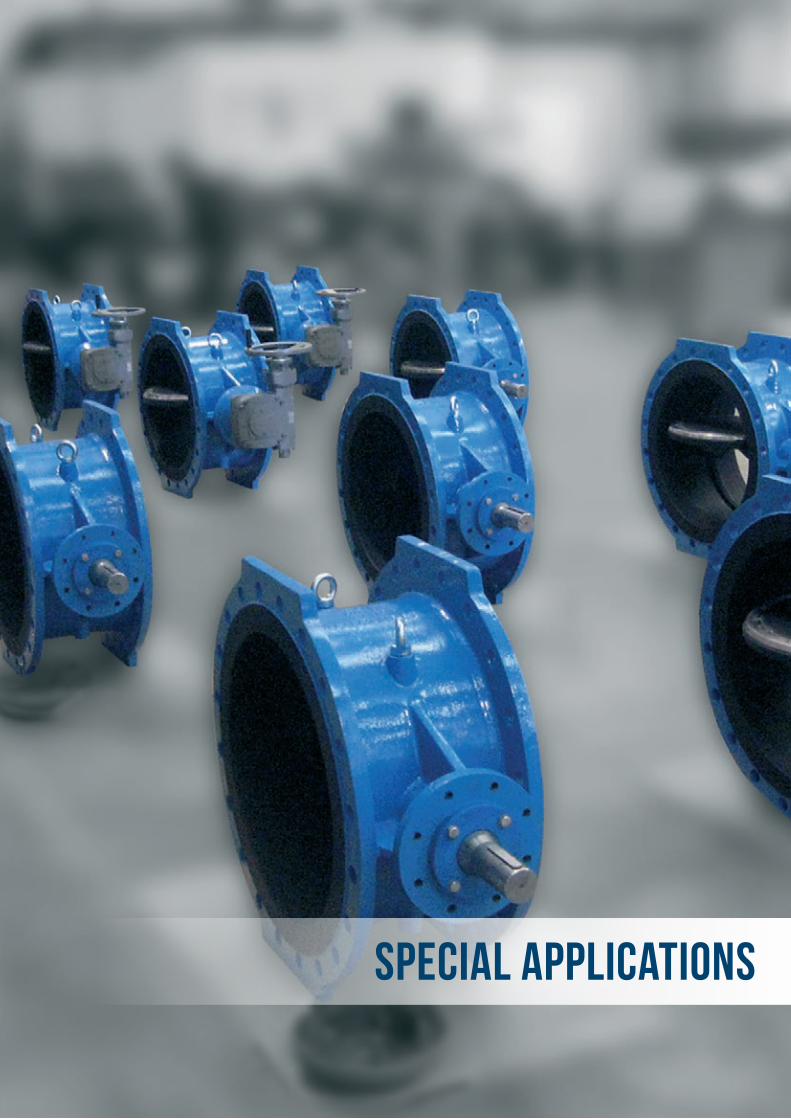
SPECIAL APPLICATIONS
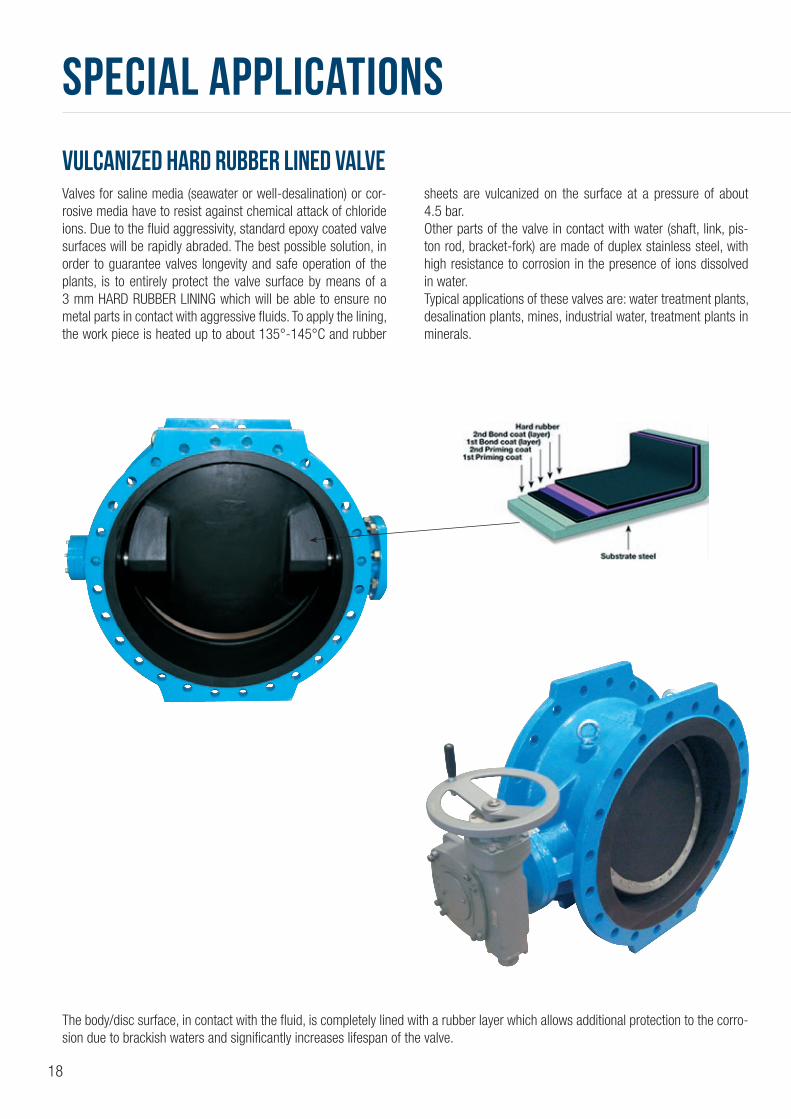
VULCANIZED HARD RUBBER LINED VALVEValves for saline media (seawater or well-desalination) or cor-rosive media have to resist against chemical attack of chloride ions. Due to the fluid aggressivity, standard epoxy coated valve surfaces will be rapidly abraded. The best possible solution, in order to guarantee valves longevity and safe operation of the plants, is to entirely protect the valve surface by means of a 3 mm HARD RUBBER LINING which will be able to ensure no metal parts in contact with aggressive fluids. To apply the lining, the work piece is heated up to about 135°-145°C and rubber
sheets are vulcanized on the surface at a pressure of about 4.5 bar.Other parts of the valve in contact with water (shaft, link, pis-ton rod, bracket-fork) are made of duplex stainless steel, with high resistance to corrosion in the presence of ions dissolved in water.Typical applications of these valves are: water treatment plants, desalination plants, mines, industrial water, treatment plants in minerals.
The body/disc surface, in contact with the fluid, is completely lined with a rubber layer which allows additional protection to the corro-sion due to brackish waters and significantly increases lifespan of the valve.
18
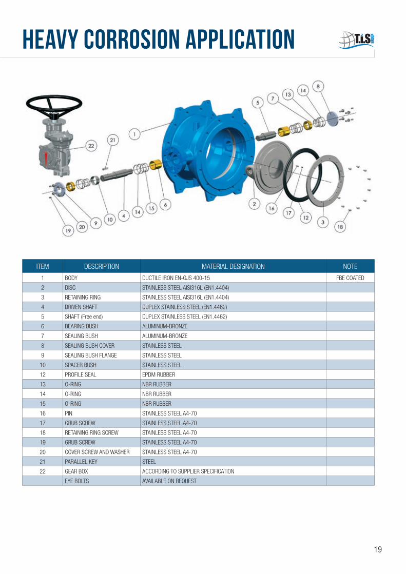
HEAVY CORROSION APPLICATION
ITEM DESCRIPTION MATERIAL DESIGNATION NOTE
1 BODY DUCTILE IRON EN-GJS 400-15 FBE COATED
2 DISC STAINLESS STEEL AISI316L (EN1.4404)
3 RETAINING RING STAINLESS STEEL AISI316L (EN1.4404)
4 DRIVEN SHAFT DUPLEX STAINLESS STEEL (EN1.4462)
5 SHAFT (Free end) DUPLEX STAINLESS STEEL (EN1.4462)
6 BEARING BUSH ALUMINUM-BRONZE
7 SEALING BUSH ALUMINUM-BRONZE
8 SEALING BUSH COVER STAINLESS STEEL
9 SEALING BUSH FLANGE STAINLESS STEEL
10 SPACER BUSH STAINLESS STEEL
12 PROFILE SEAL EPDM RUBBER
13 O-RING NBR RUBBER
14 O-RING NBR RUBBER
15 O-RING NBR RUBBER
16 PIN STAINLESS STEEL A4-70
17 GRUB SCREW STAINLESS STEEL A4-70
18 RETAINING RING SCREW STAINLESS STEEL A4-70
19 GRUB SCREW STAINLESS STEEL A4-70
20 COVER SCREW AND WASHER STAINLESS STEEL A4-70
21 PARALLEL KEY STEEL
22 GEAR BOX ACCORDING TO SUPPLIER SPECIFICATION
EYE BOLTS AVAILABLE ON REQUEST
19

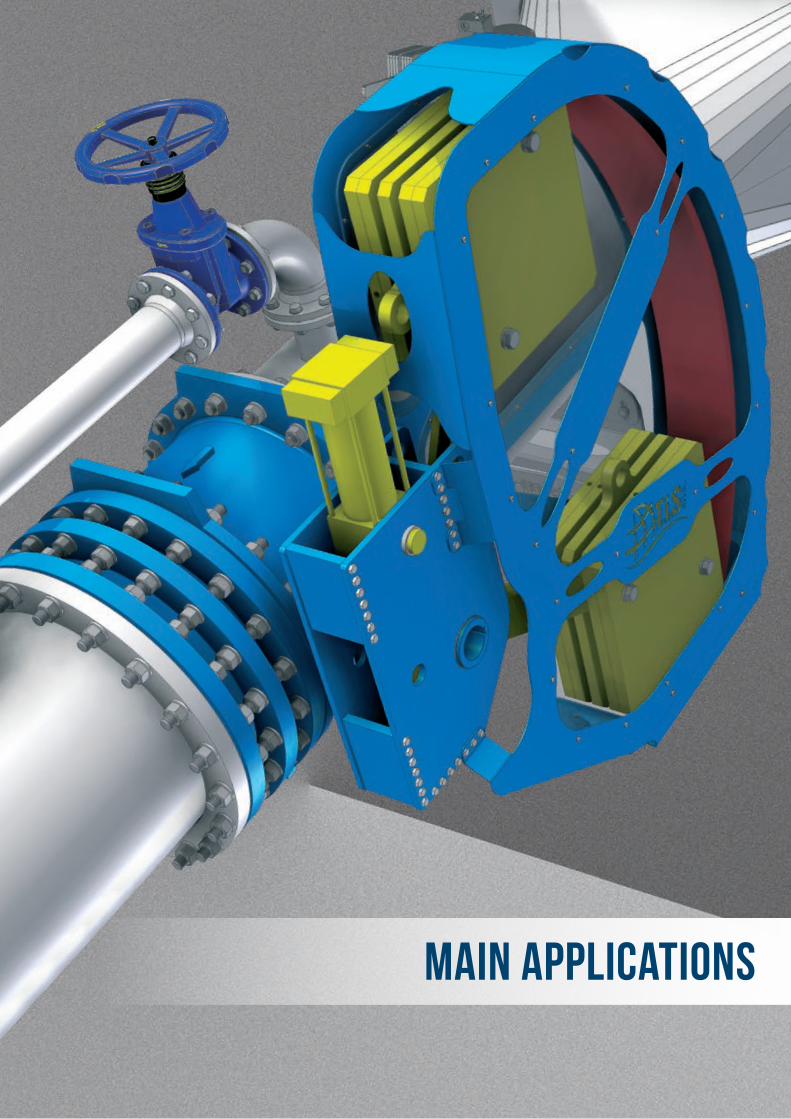
MAIN APPLICATIONS
MAIN APPLICATIONS
SAFETY FUNCTION
SAFETY FUNCTION WITH OVER VELOCITY SENSOR
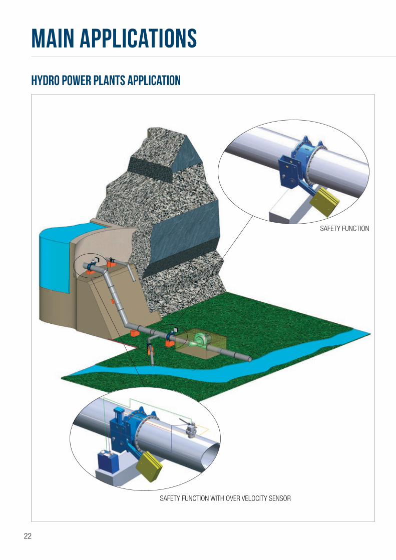
Hydro power plantS application
22
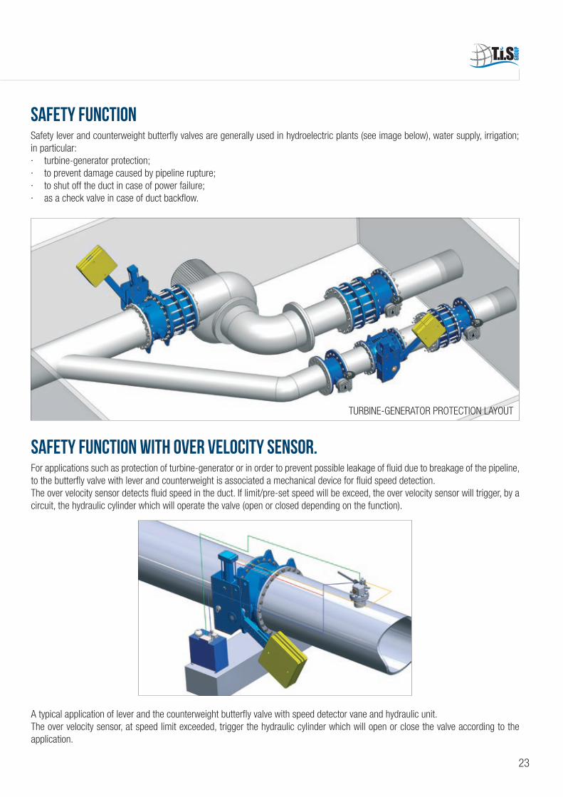
SAFETY Function WITH OVER VELOCITY SENSOR.For applications such as protection of turbine-generator or in order to prevent possible leakage of fluid due to breakage of the pipeline, to the butterfly valve with lever and counterweight is associated a mechanical device for fluid speed detection.The over velocity sensor detects fluid speed in the duct. If limit/pre-set speed will be exceed, the over velocity sensor will trigger, by a circuit, the hydraulic cylinder which will operate the valve (open or closed depending on the function).
A typical application of lever and the counterweight butterfly valve with speed detector vane and hydraulic unit.The over velocity sensor, at speed limit exceeded, trigger the hydraulic cylinder which will open or close the valve according to the application.
SAFETY FUNCTIONSafety lever and counterweight butterfly valves are generally used in hydroelectric plants (see image below), water supply, irrigation; in particular:· turbine-generator protection;· to prevent damage caused by pipeline rupture;· to shut off the duct in case of power failure;· as a check valve in case of duct backflow.
TURBINE-GENERATOR PROTECTION LAYOUT
23
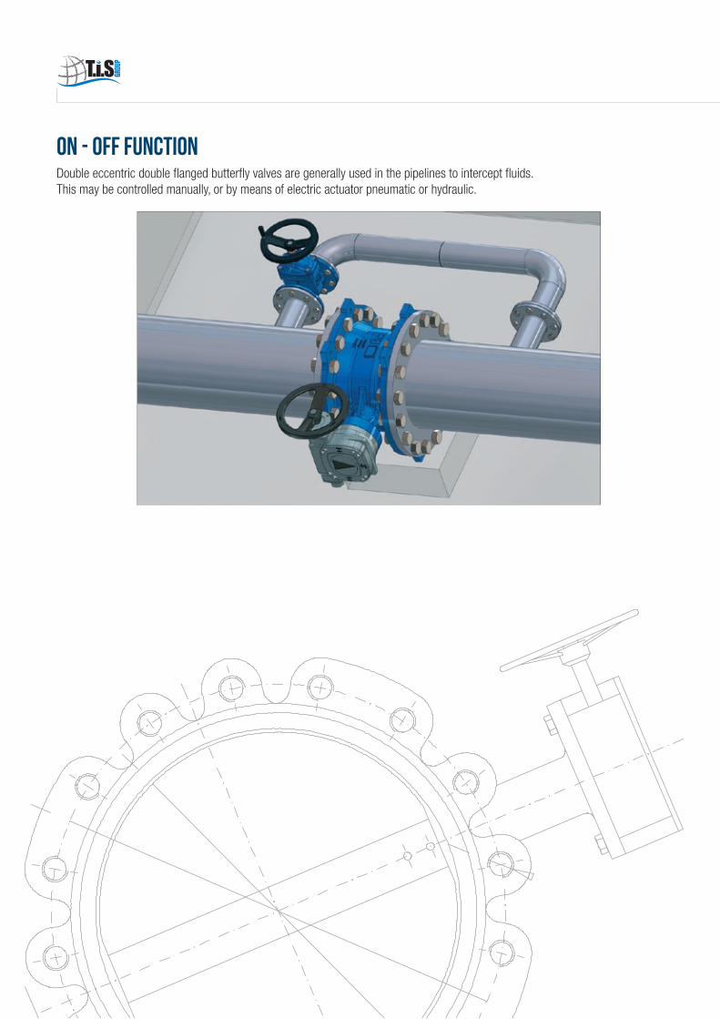
ON - OFF FUNCTIONDouble eccentric double flanged butterfly valves are generally used in the pipelines to intercept fluids.This may be controlled manually, or by means of electric actuator pneumatic or hydraulic.

ASSOCIATED
Federazione delle Associazioni Nazionalidell'Industria Meccanica Varia ed Affine
DOUBLE ECCENTRIC DOUBLE FLANGED BUTTERFLY VALVES
TIS GRoupTIS asia
T.I.S. Service S.p.A.Via Lago d’Iseo 4,6 - 24060 Bolgare (BG) - Italy
ED. 0
1/20
17
Tel. +39/035/83.54.811 - Fax +39/035/83.54.888www.TISGROUP.IT - [email protected]
VALVES DEDICATED TO THE WATER DISTRIBUTION NETWORKAND HYDROPOWER SECTOR
WE DO NOT SELL JUST VALVES, WE SELL A SOLUTION FOR THE EFFICIENCY OF THE WATER NETWORK
ISTANBUL TURKEY
UNI EN ISO 9001:2008