Embed Size (px)
Citation preview
ASE 8 - Engine Performance
Module 9Ignition Systems

AcknowledgementsGeneral Motors, the IAGMASEP Association Board of Directors, and RaytheonProfessional Services, GM's training partner for GM's Service Technical College wish tothank all of the people who contributed to the GM ASEP/BSEP curriculum developmentproject 2002-3. This project would not have been possible without the tireless efforts ofmany people. We acknowledge:
• The IAGMASEP Association members for agreeing to tackle this large project tocreate the curriculum for the GM ASEP/BSEP schools.
• The IAGMASEP Curriculum team for leading the members to a single vision andimplementation.
• Direct contributors within Raytheon Professional Services for their support oftranslating a good idea into reality. Specifically, we thank:
– Chris Mason and Vince Williams, for their leadership, guidance, and support.– Media and Graphics department under Mary McClain and in particular, Cheryl
Squicciarini, Diana Pajewski, Lesley McCowey, Jeremy Pawelek, & NancyDeSantis.
– For their help on the Engine Performance curriculum volume, Subject MatterExperts, John Beggs and Stephen Scrivner, for their wealth of knowledge.
Finally, we wish to recognize the individual instructors and staffs of the GM ASEP/BSEPColleges for their contribution for reformatting existing General Motors training material,adding critical technical content and the sharing of their expertise in the GM product.Separate committees worked on each of the eight curriculum areas. For the work on thisvolume, we thank the members of the Engine Performance committee:
– Jamie Decato, New Hampshire Community Technical College– Lorenza Dickerson, J. Sargeant Reynolds Community College– Marvin Johnson, Brookhaven College– Jeff Rehkopf, Florida Community College at Jacksonville– David Rodriguez, College of Southern Idaho– Paul Tucker, Brookdale Community College– Kelly Smith, University of Alaska– Ray Winiecki, Oklahoma State University - Okmulgee

ContentsModule 9 - Ignition SystemsOverview .......................................................................................................... 4
Primary Circuit ................................................................................................................ 5Triggering ........................................................................................................................ 5Secondary Circuit ............................................................................................................ 5Coil .................................................................................................................................. 5The Principle of Mutual Induction ................................................................................... 6Types of Systems ........................................................................................................... 7Distributor Ignition ........................................................................................................... 7DI Secondary Operation ................................................................................................. 8Spark Plugs ..................................................................................................................... 9Electronic Ignition (EI) ....................................................................................................11EI Secondary Operation................................................................................................ 12Types of Systems ......................................................................................................... 13IC Timing ....................................................................................................................... 15Triggering Devices ........................................................................................................ 15Permanent Magnet (PM) Generator ............................................................................. 16Integrated Direct Ignition (IDI) ....................................................................................... 18Up-Integrated Direct Ignition (UIDI) .............................................................................. 204.0L, 4.6L Direct Ignition System (DIS) ......................................................................... 20Hall Effect Switch .......................................................................................................... 21Computer Controlled Coil Ignition (C31) ....................................................................... 23C31 Crank and Cam Sensors ....................................................................................... 24C31 Type 1 & 2 Fast Start ............................................................................................. 25Crankshaft Sensor Adjustment ..................................................................................... 27Single Shot Sensor Adjustment .................................................................................... 28Ignition Control - 3100/3400.......................................................................................... 293100-3400 3X Reference Low ...................................................................................... 30Camshaft Position (CMP) Sensor ................................................................................. 30Magneto Resistive Sensors .......................................................................................... 32

HVS Distributor Ignition System Overview .................................................................... 34Ignition Control .............................................................................................................. 35Camshaft Retard Offset Adjustment (Truck V8) ............................................................ 38Coil-Near-Plug .............................................................................................................. 39Crankshaft Position Sensor and Reluctor Wheel .......................................................... 39Camshaft Position Sensor ............................................................................................ 40Ignition Coils/Modules ................................................................................................... 40Optical Pick-Up Sensor ................................................................................................. 44Opti-Spark Ignition System ........................................................................................... 45Noteworthy Ignition Information .................................................................................... 47Diagnosing Ignition Systems......................................................................................... 47Coil-On-Plug Ignition System ........................................................................................ 49Spark Plugs ................................................................................................................... 50Powertrain Control Module ........................................................................................... 50Dual Knock Sensors ..................................................................................................... 51Crankshaft Position (CKP) Sensor ................................................................................ 52Camshaft Position (CMP) Sensor ................................................................................. 52

© 2002 General Motors CorporationAll Rights Reserved
ASE 8- EnginePerformance
Module 9 -Ignition Systems
9-5
Student WorkbookOverviewIgnition systems have changed significantly in recent years. They havegone from mechanically driven distributors with breaker points, to anelectronically controlled distributorless system (Figure 8-1). Emissions andfuel economy requirements, together with changing engine designs andpackaging needs, have all contributed to these changes.As a result of the combustion characteristics of today's engines (high swirl/turbulence), and the dilution of the mixture due to EGR gases, the energyrequirements of the ignition system have increased significantly. To meetthese requirements, today's ignition systems are capable of producingvoltages greater than 1 00,000 volts. At the same time, these newersystems require little or no maintenance, as compared to the oldermechanical systems.This section will describe the different types of ignition systems currentlybeing used. It will cover the components and operation of the mostcommonly used GM systems.
While discussing ignition secondary systems, we will use electron flowinstead of conventional current flow. Conventional flow is from positive tonegative; electron flow is from negative to positive.On conventional distributor ignition systems, the center terminal of theplug is always negative. That is, the electrons leave from the centerelectrode and arrive at the outer electrode. The electrons return throughthe block and other circuitry to the source, the secondary coil winding.Consider the secondary winding as a source in itself; the energy does nothave to be common to the 12 volt source at any point to operate properly.All ignition systems are made up of three sections or sub-groups (Figure8-2):• Primary• Triggering• Secondary
Figure 8-1, Typical Ignition System
© 2002 General Motors CorporationAll Rights Reserved
ASE 8- EnginePerformance
Module 9 -Ignition Systems
9-6
Student Workbook
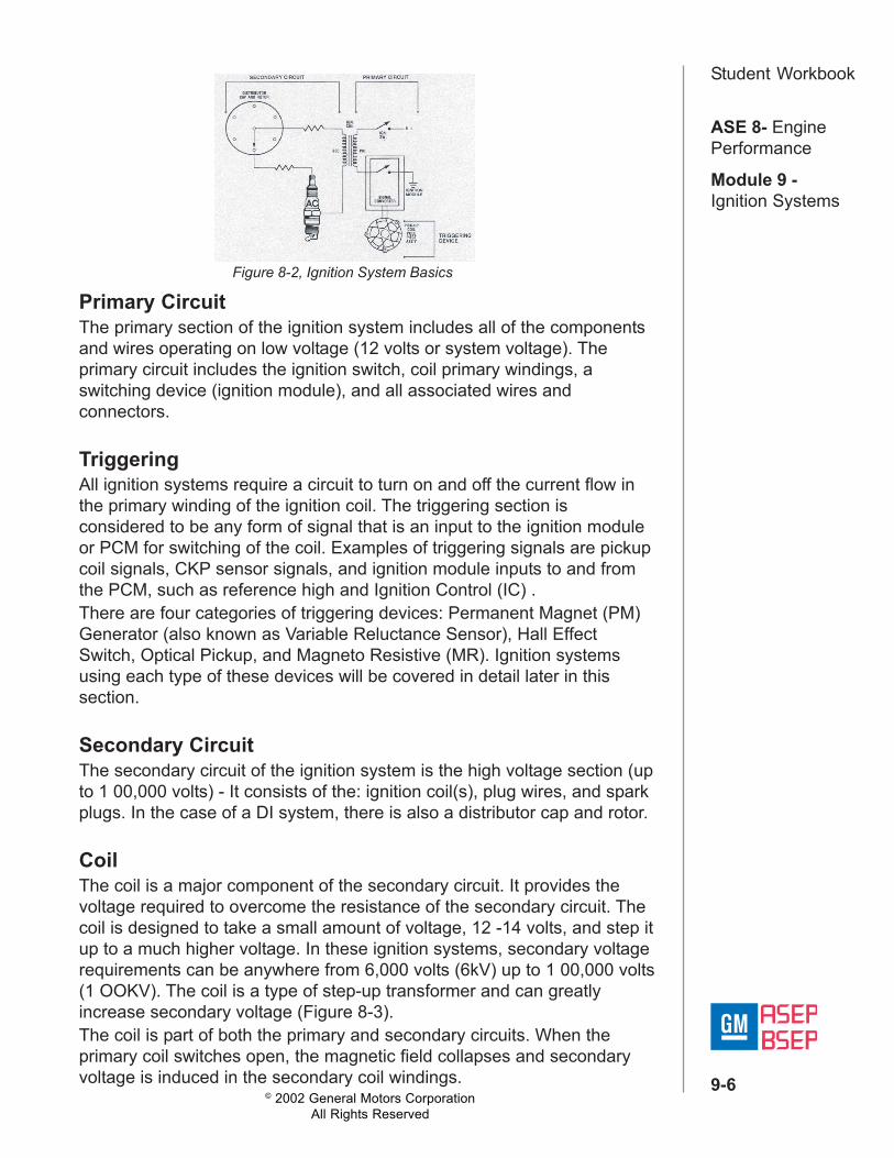
Primary CircuitThe primary section of the ignition system includes all of the componentsand wires operating on low voltage (12 volts or system voltage). Theprimary circuit includes the ignition switch, coil primary windings, aswitching device (ignition module), and all associated wires andconnectors.
TriggeringAll ignition systems require a circuit to turn on and off the current flow inthe primary winding of the ignition coil. The triggering section isconsidered to be any form of signal that is an input to the ignition moduleor PCM for switching of the coil. Examples of triggering signals are pickupcoil signals, CKP sensor signals, and ignition module inputs to and fromthe PCM, such as reference high and Ignition Control (IC) .There are four categories of triggering devices: Permanent Magnet (PM)Generator (also known as Variable Reluctance Sensor), Hall EffectSwitch, Optical Pickup, and Magneto Resistive (MR). Ignition systemsusing each type of these devices will be covered in detail later in thissection.
Secondary CircuitThe secondary circuit of the ignition system is the high voltage section (upto 1 00,000 volts) - It consists of the: ignition coil(s), plug wires, and sparkplugs. In the case of a DI system, there is also a distributor cap and rotor.
CoilThe coil is a major component of the secondary circuit. It provides thevoltage required to overcome the resistance of the secondary circuit. Thecoil is designed to take a small amount of voltage, 12 -14 volts, and step itup to a much higher voltage. In these ignition systems, secondary voltagerequirements can be anywhere from 6,000 volts (6kV) up to 1 00,000 volts(1 OOKV). The coil is a type of step-up transformer and can greatlyincrease secondary voltage (Figure 8-3).The coil is part of both the primary and secondary circuits. When theprimary coil switches open, the magnetic field collapses and secondaryvoltage is induced in the secondary coil windings.
Figure 8-2, Ignition System Basics

© 2002 General Motors CorporationAll Rights Reserved
ASE 8- EnginePerformance
Module 9 -Ignition Systems
9-7
Student WorkbookThe Principle of Mutual InductionA current flow through a primary coil winding produces a magnetic fieldthrough a second coil winding, wound around a common steel core. Whenthe primary coil current is shut off, the magnetic field collapses and currentis "induced" in the secondary windings.
Coil output is affected by three factors. The first is the amount of currentthat can flow through the primary winding. The more current that can flowthen the stronger the magnetic field will be. The second is the number ofturns of wire on the secondary side. The more turns, the higher thevoltage output. The third is the diameter of the wire used. These factorstogether dictate the coils output (Figure 8-4).Several factors limit ignition coil output. When a coil steps up voltage, theamperage is proportionally decreased. If the current flow through the coilprimary winding is low, the current on the secondary side may besignificantly lower. If secondary resistance becomes excessive, there maynot be enough energy to jump the spark plug gap. This could cause amisfire, or possibly damage the coil or ignition module.
Figure 8-3, Basic Induction Principles
Figure 8-4, Cross-Section of Remote Mounted Ignition Coil

© 2002 General Motors CorporationAll Rights Reserved
ASE 8- EnginePerformance
Module 9 -Ignition Systems
9-8
Student WorkbookTypes of SystemsAlthough there are many variationsof ignition systems currently beingused, they all fall into two majorcategories: Distributor Ignition (DI)systems and Electronic Ignition (El)systems.
Distributor IgnitionDistributor Ignition (DI) systems withelectronic controls have been usedon GM engines since the mid-seventies,Since that time, they have beenconstantly refined and improved.Ignition systems have evolved andtoday are highly sophisticatedelectronic systems with fewermoving parts and minimaladjustments. Timing is computer-controlled and better meets thechanging conditions of the engine.The most common form of DI is theHigh Energy Ignition system (HEI).Some advantages of the HEI system are:• The ability to fire EGR diluted mixtures under high swirl/turbulence
conditions• Extended spark plug life• Fewer moving parts with reduced service• The signal for ignition timing can be precisely controlled by the PCM• Coil primary current is controlled electronically by solid-state circuitry
ComponentsThe typical HEI system contains:• Distributor Assembly (Figure 8-5)• Pickup Coil• Ignition Module• Ignition Coil• Cap and Rotor
Figure 8-5, Distributor Assembly
© 2002 General Motors CorporationAll Rights Reserved
ASE 8- EnginePerformance
Module 9 -Ignition Systems
9-9
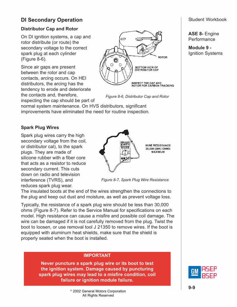
Student WorkbookDI Secondary OperationDistributor Cap and RotorOn DI ignition systems, a cap androtor distribute (or route) thesecondary voltage to the correctspark plug at each cylinder(Figure 8-6).Since air gaps are presentbetween the rotor and capcontacts, arcing occurs. On HEIdistributors, the arcing has thetendency to erode and deterioratethe contacts and, therefore,inspecting the cap should be part ofnormal system maintenance. On HVS distributors, significantimprovements have eliminated the need for routine inspection.
Spark Plug WiresSpark plug wires carry the highsecondary voltage from the coil,or distributor cal), to the sparkplugs. They are made ofsilicone rubber with a fiber corethat acts as a resistor to reducesecondary current. This cutsdown on radio and televisioninterference (TVRS), andreduces spark plug wear.The insulated boots at the end of the wires strengthen the connections tothe plug and keep out dust and moisture, as well as prevent voltage loss.Typically, the resistance of a spark plug wire should be less than 30,000ohms (Figure 8-7). Refer to the Service Manual for specifications on eachmodel. High resistance can cause a misfire and possible coil damage. Thewire can be damaged if it is not carefully removed from the plug. Twist theboot to loosen, or use removal tool J 21350 to remove wires. If the boot isequipped with aluminum heat shields, make sure that the shield isproperly seated when the boot is installed.
IMPORTANTNever puncture a spark plug wire or its boot to testthe ignition system. Damage caused by puncturing
spark plug wires may lead to a misfire condition, coilfailure or ignition module failure.
Figure 8-7, Spark Plug Wire Resistance
Figure 8-6, Distributor Cap and Rotor
© 2002 General Motors CorporationAll Rights Reserved
ASE 8- EnginePerformance
Module 9 -Ignition Systems
9-10
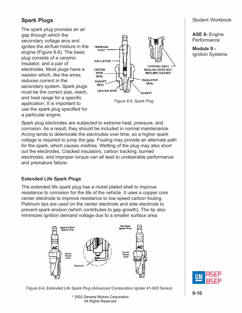
Student WorkbookSpark PlugsThe spark plug provides an airgap through which thesecondary voltage arcs andignites the air/fuel mixture in theengine (Figure 8-8). The basicplug consists of a ceramicinsulator, and a pair ofelectrodes. Most plugs have aresistor which, like the wires,reduces current in thesecondary system. Spark plugsmust be the correct size, reach,and heat range for a specificapplication. It is important touse the spark plug specified fora particular engine.Spark plug electrodes are subjected to extreme heat, pressure, andcorrosion. As a result, they should be included in normal maintenance.Arcing tends to deteriorate the electrodes over time, so a higher sparkvoltage is required to jump the gap. Fouling may provide an alternate pathfor the spark, which causes misfires. Wetting of the plug may also shortout the electrodes. Cracked insulators, carbon tracking, burnedelectrodes, and improper torque can all lead to undesirable performanceand premature failure.
Extended Life Spark PlugsThe extended life spark plug has a nickel plated shell to improveresistance to corrosion for the life of the vehicle. It uses a copper corecenter electrode to improve resistance to low speed carbon fouling.Platinum tips are used on the center electrode and side electrode toprevent spark erosion (which contributes to gap growth). The tip alsominimizes ignition demand voltage due to a smaller surface area.
Figure 8-8, Spark Plug
Figure 8-9, Extended Life Spark Plug (Advanced Composition Igniter 41-900 Series)
© 2002 General Motors CorporationAll Rights Reserved
ASE 8- EnginePerformance
Module 9 -Ignition Systems
9-11
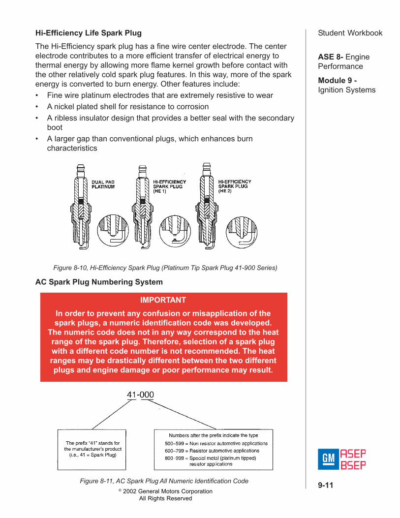
Student WorkbookHi-Efficiency Life Spark PlugThe Hi-Efficiency spark plug has a fine wire center electrode. The centerelectrode contributes to a more efficient transfer of electrical energy tothermal energy by allowing more flame kernel growth before contact withthe other relatively cold spark plug features. In this way, more of the sparkenergy is converted to burn energy. Other features include:• Fine wire platinum electrodes that are extremely resistive to wear• A nickel plated shell for resistance to corrosion• A ribless insulator design that provides a better seal with the secondary
boot• A larger gap than conventional plugs, which enhances burn
characteristics
AC Spark Plug Numbering System
Figure 8-10, Hi-Efficiency Spark Plug (Platinum Tip Spark Plug 41-900 Series)
Figure 8-11, AC Spark Plug All Numeric Identification Code
IMPORTANTIn order to prevent any confusion or misapplication of thespark plugs, a numeric identification code was developed.
The numeric code does not in any way correspond to the heatrange of the spark plug. Therefore, selection of a spark plugwith a different code number is not recommended. The heatranges may be drastically different between the two differentplugs and engine damage or poor performance may result.

© 2002 General Motors CorporationAll Rights Reserved
ASE 8- EnginePerformance
Module 9 -Ignition Systems
9-12
Student WorkbookElectronic Ignition (EI)The Electronic Ignition (EI) system was designed to replace themechanical Distributor Ignition (DI) system. EI eliminates many of themechanical parts of a DI system that could possibly fail.
ComponentsThe components that makeup a typical El system arelisted below (Figure 8-12):• Ignition Module• Ignition Coils• Crankshaft Sensor• Camshaft Sensor (in
some applications)• Interrupter or Reluctor
Advantages• Fewer moving parts• More compact mounting• Remote mounting capability• Elimination of mechanical timing adjustments• Less maintenance• No mechanical load on engine• Increased available coil saturation time (dwell time)• More coil cool down time between firing events
The terms that are used when referring to the Electronic Ignition (EI)System are determined by the actual vehicle application of the system.The EI systems currently used are:• Computer Controlled Coil Ignition (C31)• Direct Ignition System (DIS)• Integrated Direct Ignition (IDI)• Up-integrated Direct Ignition (UIDI)• Coil Per Plug (CPP)
Figure 8-12, EI Components

© 2002 General Motors CorporationAll Rights Reserved
ASE 8- EnginePerformance
Module 9 -Ignition Systems
9-13
Student WorkbookEI Secondary OperationIn an EI System, a spark plug isattached to each end of theignition coil secondary. Each coilof the system fires the plugs intwo companion cylinders (Figure8-13). These are cylinders thatreach Top Dead Center (TDC) atthe same time. The cylinder thatis at TDC on the compressionstroke is referred to as the"event" cylinder while the cylinderat TDC on the exhaust stroke isthe "waste" cylinder. When thecoil discharges, both plugs fire atthe same time to complete theseries circuit.Since the polarities of the ignitionprimary and secondary windingsare fixed, one plug always fires ina forward direction, while theother always fires in reverse(Figure 8-14). This arrangementrequires somewhat more energythan conventional systems. Coildesign, saturation time andprimary current flow on Elsystems are able to produce thenecessary energy to accomplishthis.Since both plugs in companioncylinders fire at the same time, itis not necessary for the module torecognize which cylinder is on which stroke. Because of lower pressure inthe cylinder on the exhaust stroke, its plug requires less voltage toproduce an arc. Therefore, most of the available voltage is used to fire theplug in the cylinder that is on the compression stroke.
Figure 8-13, Companion Cylinders
Figure 8-14, EI Current Flow
CAUTIONNo ignition coil is designed to be run with the secondary
unloaded. However, this is particularly true withdistributorless ignition systems. The high voltage producedby these systems can cause personal injury and/or system
component damage.

© 2002 General Motors CorporationAll Rights Reserved
ASE 8- EnginePerformance
Module 9 -Ignition Systems
9-14
Student WorkbookIMPORTANT
A spark tester that requires 25,000 volts is required toadequately load the secondary portion of the ignition system(ST-1 25, J-26792). Other spark testers may not require 25,000
volts and therefore could lead to misdiagnosis.
Types of SystemsSo far, we have covered two types of ignition systems; Distributor Ignition(DI) systems and Electronic Ignition (EI) systems. These can be furtherbroken down into two sub-categories:• Up-Integrated Systems• Bypass Systems
Up-Integrated SystemsIn an up-integrated ignition system (figure 8-16), all ignition coil timing iscontrolled by the PCM. The triggering signal, from either the crankshaftposition (CKP) sensor or the pickup coil, is a direct input to the PCM. ThePCM processes the triggering signal, along with other inputs, and providesthe ignition control module with an ON/OFF signal. Based on the ON/OFFsignals from the PCM, the ignition control module turns the coils on andoff, providing secondary voltage for the spark plugs to fire.The main function of the ignition control module in an up-integratedsystem is to:• Turn the coils on and off based on IC signals from the PCM Limit
primary current flow (in some applications)In some cases, the ignition control module still receives the CKP signal.The ignition control module, in these cases, is just a processor for theCKP signal. It passes the signal to the PCM, sometimes converting it froman AC signal to a DC signal, but has no control of ignition timing.
Figure 8-16, Up-Integrated System
© 2002 General Motors CorporationAll Rights Reserved
ASE 8- EnginePerformance
Module 9 -Ignition Systems
9-15
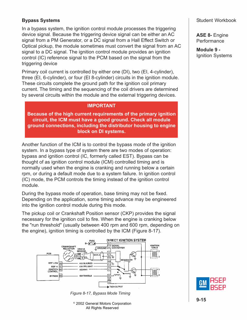
Student WorkbookBypass SystemsIn a bypass system, the ignition control module processes the triggeringdevice signal. Because the triggering device signal can be either an ACsignal from a PM Generator, or a DC signal from a Hall Effect Switch orOptical pickup, the module sometimes must convert the signal from an ACsignal to a DC signal. The ignition control module provides an ignitioncontrol (IC) reference signal to the PCM based on the signal from thetriggering devicePrimary coil current is controlled by either one (DI), two (EI, 4-cylinder),three (EI, 6-cylinder), or four (EI 8-cylinder) circuits in the ignition module.These circuits complete the ground path for the ignition coil primarycurrent. The timing and the sequencing of the coil drivers are determinedby several circuits within the module and the external triggering devices.
Another function of the ICM is to control the bypass mode of the ignitionsystem. In a bypass type of system there are two modes of operation:bypass and ignition control (IC, formerly called EST). Bypass can bethought of as ignition control module (ICM) controlled timing and isnormally used when the engine is cranking and running below a certainrpm, or during a default mode due to a system failure. In ignition control(IC) mode, the PCM controls the timing instead of the ignition controlmodule.During the bypass mode of operation, base timing may not be fixed.Depending on the application, some timing advance may be engineeredinto the ignition control module during this mode.The pickup coil or Crankshaft Position sensor (CKP) provides the signalnecessary for the ignition coil to fire. When the engine is cranking belowthe "run threshold" (usually between 400 rpm and 600 rpm, depending onthe engine), ignition timing is controlled by the ICM (Figure 8-17).
IMPORTANTBecause of the high current requirements of the primary ignition
circuit, the ICM must have a good ground. Check all moduleground connections, including the distributor housing to engine
block on DI systems.
Figure 8-17, Bypass Mode Timing
© 2002 General Motors CorporationAll Rights Reserved
ASE 8- EnginePerformance
Module 9 -Ignition Systems
9-16
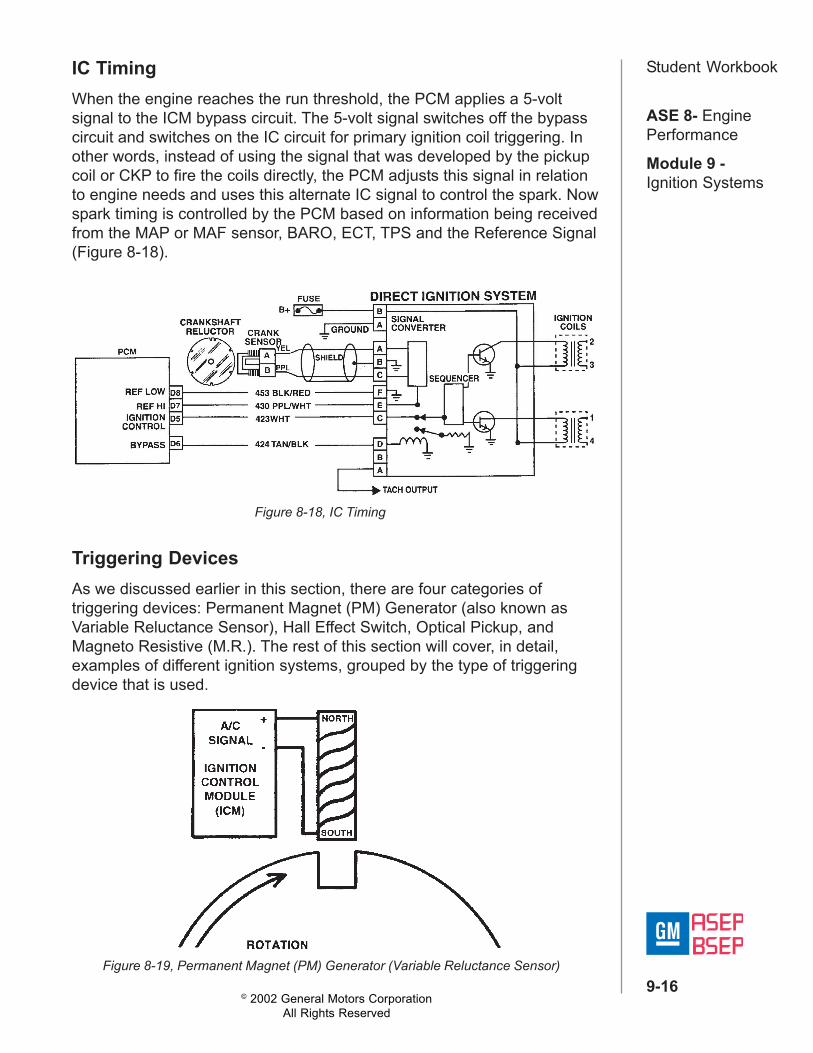
Student WorkbookIC TimingWhen the engine reaches the run threshold, the PCM applies a 5-voltsignal to the ICM bypass circuit. The 5-volt signal switches off the bypasscircuit and switches on the IC circuit for primary ignition coil triggering. Inother words, instead of using the signal that was developed by the pickupcoil or CKP to fire the coils directly, the PCM adjusts this signal in relationto engine needs and uses this alternate IC signal to control the spark. Nowspark timing is controlled by the PCM based on information being receivedfrom the MAP or MAF sensor, BARO, ECT, TPS and the Reference Signal(Figure 8-18).
Figure 8-18, IC Timing
Triggering DevicesAs we discussed earlier in this section, there are four categories oftriggering devices: Permanent Magnet (PM) Generator (also known asVariable Reluctance Sensor), Hall Effect Switch, Optical Pickup, andMagneto Resistive (M.R.). The rest of this section will cover, in detail,examples of different ignition systems, grouped by the type of triggeringdevice that is used.
Figure 8-19, Permanent Magnet (PM) Generator (Variable Reluctance Sensor)

© 2002 General Motors CorporationAll Rights Reserved
ASE 8- EnginePerformance
Module 9 -Ignition Systems
9-17
Student WorkbookPermanent Magnet (PM)GeneratorThe PM generator uses theprinciple of induction to developan AC signal. In the example ofthe cranksensor, Figure 8-19, wire iscoiled around a permanentmagnet. By rotating a reluctor,which has notches cutinto it at precise locations, themagnetic field moves back andforth across the wire winding.This produces an AC voltagesignal in the wire. The ends ofthe wires are connected toeither the ICM or the PCM. Thesignal is converted to an ON/OFF reference and used as thebase triggering for the primarycircuit.For the crankshaft positionsensor to work, it must have a.050" (± .020") air gap betweenthe sensor and the reluctor. OnEl systems the sensor ismounted in the block or thefront cover and is non-adjustable.On a DI system, the pickup coil operates similarly. A magnetic fieldincreases and decreases as the teeth of the timer core and the pole piecemove in and out of alignment (Figure 8-20). This induces an alternatingcurrent flow through the pickup coil, which is the triggering signal to theICM.
Law of Induction"Electricity creates magnetism, and magnetism creates electricity..." Inother words, current flowing through a conductor creates a small magneticfield around the conductor. And conversely, any time a magnetic field isallowed to cut through a conductor, current flow is produced in theconductor. It is this principle that is used in PM Generators.
Figure 8-20, Pickup Coil Operation

© 2002 General Motors CorporationAll Rights Reserved
ASE 8- EnginePerformance
Module 9 -Ignition Systems
9-18
Student WorkbookPM Generator outputvoltage varies with enginespeed. Typical values rangefrom approximately 500millivolts at cranking speedsto 100 volts at high rpm,depending on theapplication. Whenmeasuring the output from amagnetic crank sensor, thevoltmeter should be set onan appropriate AC scale.The output from a PMGenerator in a given enginewill vary based upon thefollowing:• Cranking speed• Air gap of sensor to
reluctor• Resistance of sensor
windings• Temperature of sensor• Strength of magnet
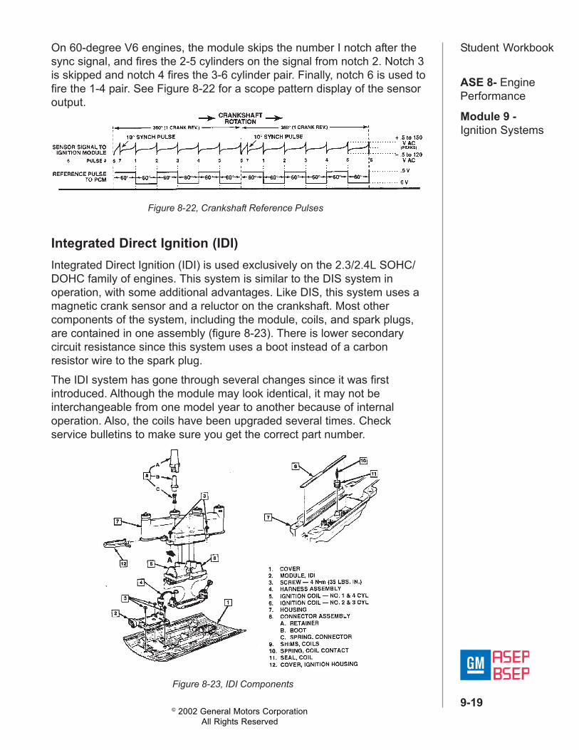
EI systems use a PMGenerator and a reluctorthat is part of the crankshaft.The design of thecrankshaft reluctor is an important consideration when diagnosing thesesystems. Crankshaft reluctors on most four- and six-cylinder engines haveseven notches that each send voltage signals to the ignition module forevery revolution of the crankshaft. Six of the notches are equally spacedat 60-degree intervals around the crankshaft. The seventh notch ispositioned 10 degrees from the sixth notch. The signal from the seventh,or "SYNC," notch synchronizes the coil firing sequence with crankshaftposition (Figure 8-21).On four-cylinder engines, the ignition module is programmed to recognizethe sync notch, count notch number 1 and accept notch 2 as the signal tofire the 2-3 companion cylinders. Next, the module counts notches 3 and4, then accepts the number 5 notch signal as the signal to fire the 1-4cylinder pair. The 6 and 7 notches are then counted and the processbegins again. Note that the coil pack for the second cylinder in the firingorder always fires first during start-up.
Figure 8-21, Reluctor/Sensor Triggering (4 and 6Cylinder Engines)
© 2002 General Motors CorporationAll Rights Reserved
ASE 8- EnginePerformance
Module 9 -Ignition Systems
9-19
Student Workbook
Figure 8-22, Crankshaft Reference Pulses
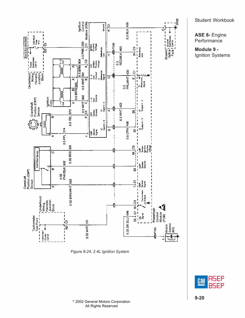
Integrated Direct Ignition (IDI)Integrated Direct Ignition (IDI) is used exclusively on the 2.3/2.4L SOHC/DOHC family of engines. This system is similar to the DIS system inoperation, with some additional advantages. Like DIS, this system uses amagnetic crank sensor and a reluctor on the crankshaft. Most othercomponents of the system, including the module, coils, and spark plugs,are contained in one assembly (figure 8-23). There is lower secondarycircuit resistance since this system uses a boot instead of a carbonresistor wire to the spark plug.The IDI system has gone through several changes since it was firstintroduced. Although the module may look identical, it may not beinterchangeable from one model year to another because of internaloperation. Also, the coils have been upgraded several times. Checkservice bulletins to make sure you get the correct part number.
Figure 8-23, IDI Components
On 60-degree V6 engines, the module skips the number I notch after thesync signal, and fires the 2-5 cylinders on the signal from notch 2. Notch 3is skipped and notch 4 fires the 3-6 cylinder pair. Finally, notch 6 is used tofire the 1-4 pair. See Figure 8-22 for a scope pattern display of the sensoroutput.
© 2002 General Motors CorporationAll Rights Reserved
ASE 8- EnginePerformance
Module 9 -Ignition Systems
9-20
Student Workbook
Figure 8-24, 2.4L Ignition System
© 2002 General Motors CorporationAll Rights Reserved
ASE 8- EnginePerformance
Module 9 -Ignition Systems
9-21
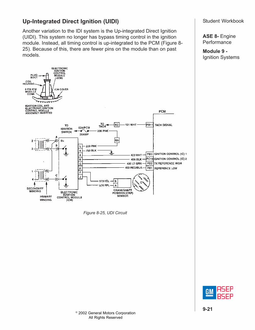
Student WorkbookUp-Integrated Direct Ignition (UIDI)Another variation to the IDI system is the Up-integrated Direct Ignition(UIDI). This system no longer has bypass timing control in the ignitionmodule. Instead, all timing control is up-integrated to the PCM (Figure 8-25). Because of this, there are fewer pins on the module than on pastmodels.
Figure 8-25, UDI Circuit

© 2002 General Motors CorporationAll Rights Reserved
ASE 8- EnginePerformance
Module 9 -Ignition Systems
9-22
Student Workbook4.0L, 4.6L Direct Ignition System (DIS)The 4.0/4.6L V8 DIS has dual variable reluctance crankshaft sensors withone reluctor ring to monitor crankshaft position (Figure 8-26). The reluctorring has 24 evenly spaced notches and 8 unevenly spaced notches. Withone sensor mounted 271, of crankshaft revolution behind the other, aunique pattern of pulses is created that allows the ignition to synchronizeand fire the first coil in less than 1/2 (18011) crankshaft revolution.The ignition module accomplishes this by monitoring the pulses it receivesfrom each crankshaft position sensor. The ignition module counts thenumber of "B" pulses between "A" pulses. The pattern on the reluctor ringallows 0, 1, or 2 B's between A's. When the module recognizes one of fourpatterns of B's between A's (0112, 01012, 0ll11, 010111), the crankshaftposition is known and the ignition system is synchronized. The ignition cansynchronize at four different crankshaft positions. Therefore, the firstcylinder fired at engine start-up will depend on where, or what position, theengine stopped at the previous key-OFF.The system also uses a magnetic camshaft position sensor for fuel controland misfire diagnostics.
Figure 8-26, 4.0L/4.6L Crankshaft Position Sensors
© 2002 General Motors CorporationAll Rights Reserved
ASE 8- EnginePerformance
Module 9 -Ignition Systems
9-23
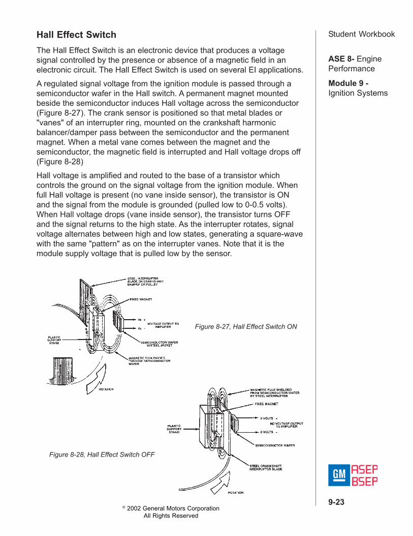
Student WorkbookHall Effect SwitchThe Hall Effect Switch is an electronic device that produces a voltagesignal controlled by the presence or absence of a magnetic field in anelectronic circuit. The Hall Effect Switch is used on several EI applications.A regulated signal voltage from the ignition module is passed through asemiconductor wafer in the Hall switch. A permanent magnet mountedbeside the semiconductor induces Hall voltage across the semiconductor(Figure 8-27). The crank sensor is positioned so that metal blades or"vanes" of an interrupter ring, mounted on the crankshaft harmonicbalancer/damper pass between the semiconductor and the permanentmagnet. When a metal vane comes between the magnet and thesemiconductor, the magnetic field is interrupted and Hall voltage drops off(Figure 8-28)Hall voltage is amplified and routed to the base of a transistor whichcontrols the ground on the signal voltage from the ignition module. Whenfull Hall voltage is present (no vane inside sensor), the transistor is ONand the signal from the module is grounded (pulled low to 0-0.5 volts).When Hall voltage drops (vane inside sensor), the transistor turns OFFand the signal returns to the high state. As the interrupter rotates, signalvoltage alternates between high and low states, generating a square-wavewith the same "pattern" as on the interrupter vanes. Note that it is themodule supply voltage that is pulled low by the sensor.
Figure 8-27, Hall Effect Switch ON
Figure 8-28, Hall Effect Switch OFF
© 2002 General Motors CorporationAll Rights Reserved
ASE 8- EnginePerformance
Module 9 -Ignition Systems
9-24
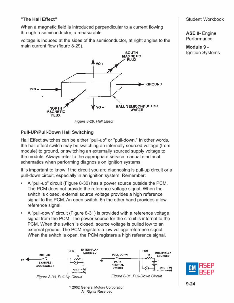
Student Workbook"The Hall Effect"When a magnetic field is introduced perpendicular to a current flowingthrough a semiconductor, a measurablevoltage is induced at the sides of the semiconductor, at right angles to themain current flow (figure 8-29).
Pull-UP/Pull-Down Hall SwitchingHall Effect switches can be either "pull-up" or "pull-down." In other words,the hall effect switch may be switching an internally sourced voltage (frommodule) to ground, or switching an externally sourced supply voltage tothe module. Always refer to the appropriate service manual electricalschematics when performing diagnosis on ignition systems.It is important to know if the circuit you are diagnosing is pull-up circuit or apull-down circuit, especially in an ignition system. Remember:• A "pull-up" circuit (Figure 8-30) has a power source outside the PCM.
The PCM does not provide the reference voltage signal. When theswitch is closed, external source voltage provides a high referencesignal to the PCM. An open switch, 6n the other hand provides a lowreference signal.
• A "pull-down" circuit (Figure 8-31) is provided with a reference voltagesignal from the PCM. The power source for the circuit is internal to thePCM. When the switch is closed, source voltage is pulled low to anexternal ground. The PCM registers a low voltage reference signal.When the switch is open, the PCM registers a high reference signal.
Figure 8-29, Hall Effect
Figure 8-30, Pull-Up Circuit Figure 8-31, Pull-Down Circuit
© 2002 General Motors CorporationAll Rights Reserved
ASE 8- EnginePerformance
Module 9 -Ignition Systems
9-25
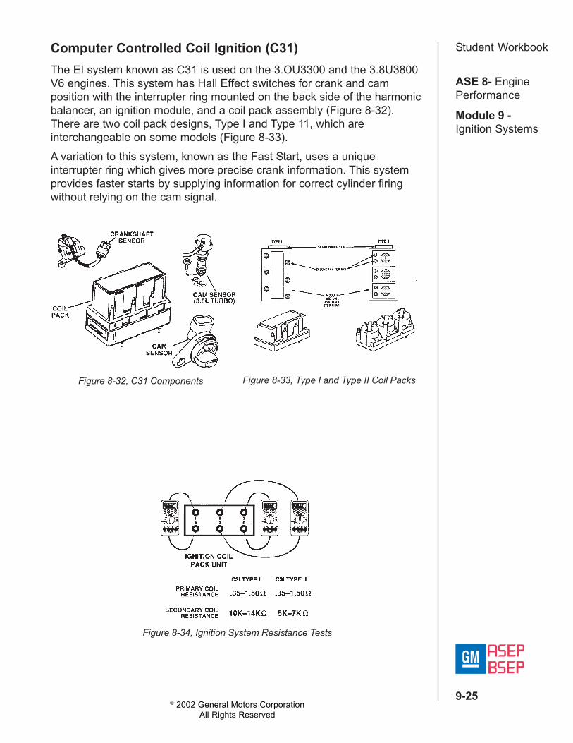
Student WorkbookComputer Controlled Coil Ignition (C31)The EI system known as C31 is used on the 3.OU3300 and the 3.8U3800V6 engines. This system has Hall Effect switches for crank and camposition with the interrupter ring mounted on the back side of the harmonicbalancer, an ignition module, and a coil pack assembly (Figure 8-32).There are two coil pack designs, Type I and Type 11, which areinterchangeable on some models (Figure 8-33).A variation to this system, known as the Fast Start, uses a uniqueinterrupter ring which gives more precise crank information. This systemprovides faster starts by supplying information for correct cylinder firingwithout relying on the cam signal.
Figure 8-32, C31 Components Figure 8-33, Type I and Type II Coil Packs
Figure 8-34, Ignition System Resistance Tests

© 2002 General Motors CorporationAll Rights Reserved
ASE 8- EnginePerformance
Module 9 -Ignition Systems
9-26
Student WorkbookC31 Crank and Cam Sensors3.0-liter, 3.8-liter, 3300 and 3800 V6 engines use Hall Effect switches forboth the crankshaft signal and the camshaft signal.The crankshaft position (CKP) sensor on the 3.0-liter engine is locatedadjacent to the crankshaft harmonic damper. Two concentric rings on theback of the damper pass on each side of the Hall Effect magnet. Theinner ring has three evenly spaced vanes and windows, which sendidentically timed signals of the same duration. The outer ring has only onewindow. This single pulse acts as the synchronize signal to set up thelogic for triggering the correct ignition coil (figure 8-36).On the 3.8-liter SFI and SFI Turbo engines, the synchronize signal isdetermined by a separate camshaft sensor. The magnet is mounted in thecamshaft sprocket (figure 8-37).The cam sensor signal identifies cylinder sequence for injector firing onSequential Fuel Injection systems, as well as the "sync" signal for theignition module.
Figure 8-35, Crankshaft Sensor,3.8L V-6 LG2 Engine
Figure 8-36, 3.0L v-6Crankshaft Position Signal
Figure 8-37, 3.8L SFI Crankshaft Position Signal

© 2002 General Motors CorporationAll Rights Reserved
ASE 8- EnginePerformance
Module 9 -Ignition Systems
9-27
Student WorkbookC31 Type 1 & 2 Fast Start3800 EngineThe C31 Fast Start system on the 3800 and 1993 3300 engines use adual crankshaft sensor and a separate cam sensor. Advantages of theFast Start system are:• Faster start-up• Walk-home protection in the event of cam sensor malfunction• More precise measurement of crankshaft sensor signals
On the Fast Start (pre 1993) systems, the dual crank sensor is mountedon the front of the engine beside the harmonic balancer/crankshaft pulley.The cam sensor is mounted on the timing cover beside the cam sprocket.The arrangement of the interrupter rings on the harmonic balancer isdifferent than on the other V6 engines. First, the outside ring has 18evenly sized and evenly spaced interrupter blades to produce 18 pulsesper crankshaft revolution. These pulses are known as the 18x signal. Theinside ring has three interrupter blades with gaps (or windows) of 10, 20and 30 degrees. These gaps, in turn, are spaced 100, 90 and 110 degreesapart respectively. These pulses are referred to as the 3x signal (Figure 8-38). With this interrupter ring arrangement, the ignition module can identifythe proper cylinder pair to fire within as little as 120 degrees of crankshaftrotation. The module can also fire any cylinder pair reaching TDC firstwithout waiting for the cam or sync. signal.The 1-4 cylinder pair reaches TDC 75 degrees after the trailing edge ofthe 10 degree window. TDC of the 6-3 pair is 75 degrees after the trailingedge of the 20 degree window. TDC of the 2-5 cylinders occurs 75degrees after the trailing edge of the 30 degree window. The trailing edgesof the windows are each 120 degrees apart.
Figure 8-38, 3800 V6 Crankshaft and Camshaft Signals

© 2002 General Motors CorporationAll Rights Reserved
ASE 8- EnginePerformance
Module 9 -Ignition Systems
9-28
Student Workbook
Figure 8-39, 3.8L Ignition System

© 2002 General Motors CorporationAll Rights Reserved
ASE 8- EnginePerformance
Module 9 -Ignition Systems
9-29
Student WorkbookCrankshaft Sensor Adjustment3.0L, 3.8L, 3300, 3800 V6sUse the crankshaft sensor adjusting tool (J-37089) to ensure accuratepositioning of the sensor, and to maintain proper clearance between theinterrupter vanes and the sensor. The tool is also used to check interrupterrings for out-of-round. The procedure for using adjusting tool J-37089(Figure 8-36) is as follows:1. Loosely install crankshaft sensor on pedestal.2. Position sensor, with pedestal attached, on adjusting tool J-37089.3. Position adjusting tool on crankshaft.4. Install bolts to hold pedestal to block face, torque to 20-40 Nm (30-35
lb. ft.).5. Torque pedestal pinch bolt to 3-4 Nm (30-35 lb. in.).6. Remove adjusting tool J-37089. Place adjusting tool J-37089 on
harmonic balancer and turn (Figure 8-40). The tool should turn freelywithout contacting any of the interrupter ring vanes. If any vanetouches the tool, replace the harmonic balancer.
Adjusting tool J-37089 can be used to adjust all crankshaft sensors, withthe exception of the Delco single-slot design sensor and late model3800s.
Figure 8-40, Crank Sensor Adjustment Using J37089

© 2002 General Motors CorporationAll Rights Reserved
ASE 8- EnginePerformance
Module 9 -Ignition Systems
9-30
Student WorkbookSingle Shot Sensor AdjustmentSingle slot design crankshaft sensors (Figure 8-41) are adjusted using theKent-Moore feeler gage style adjusting tool, J36179 as follows (Figure 8-42).1. Rotate the harmonic balancer with a 28mm socket and a pull handle,
until the interrupter ring fills the sensor slot and the edge of interrupterwindow is aligned with the edge of the deflector on the pedestal.
2. Insert adjustment tool (J-36179 or equivalent) into gap between sensorand interrupter on each side of interrupter ring. If gage does not slidepast the sensor on either side of interrupter ring, the sensor is out ofadjustment or the interrupter ring is bent. This clearance should bechecked at three positions around the outer interrupter ring,approximately 120 degrees apart.
3. Loosen the pinch bolt on sensor pedestal. Insert adjustment tool (J-36179 or equivalent) into the gap between the sensor and interrupteron each side of the interrupter ring (Figure 8-42).
4. Slide the sensor into contact against gage and interrupter ring.5. Torque the sensor retaining pinch bolt to 3.4 Nm (30 in. lbs.) while
maintaining light pressure on the sensor against the gage andinterrupter ring. Check again at three locations approximately 120degrees apart. If the interrupter ring contacts the sensor at any pointduring harmonic balancer rotation, the interrupter ring has excessiverunout and must be replaced.
Figure 8-41, Single Shot DesignCrankshaft Sensor
Figure 8-42, Crank Sensor AdjustmentUsing J36179

© 2002 General Motors CorporationAll Rights Reserved
ASE 8- EnginePerformance
Module 9 -Ignition Systems
9-31
Student WorkbookIgnition Control - 3100/3400The 3100/3400 ignition system is a hybrid ignition system that uses twocrankshaft position sensors. The 24X (Hall Switch) CKP signal is directlyinput to the PCM, while a 7X (Permanent Magnet Style) CKP signal isinput to the ignition control module. The ignition control module sends a3X signal to the PCM. The 3X signal is a conditioned signal (by the ignitioncontrol module) based on the 7X CKP signal.Below 1250 RPM, the PCM controls ignition timing and idle speed usingthe CKP 24X signal. Minor changes in idle speed are corrected by thePCM with spark control, known as "dynamic spark" Major changes arehandled by the IAC motor (Figure 8-43).
Figure 8-43, Closed Loop Idle Control
Figure 8-44, 24X Crankshaft Position Sensor

© 2002 General Motors CorporationAll Rights Reserved
ASE 8- EnginePerformance
Module 9 -Ignition Systems
9-32
Student Workbook3100-3400 3X Reference LowThe PCM uses the 3X signal from the ignition control module to calculateengine speed and crankshaft position over 1250 RPM. If the PCMreceives no pulses on this circuit, DTC P 1374 sets and the PCM uses the24X reference signal circuit for fuel and ignition control.
Camshaft Position (CMP) SensorThe CMP sensor (Figure 8-45) sends a cam position signal to the PCM,which uses it as a sync pulse to trigger the injectors in proper sequence.The PCM uses the CMP signal to indicate the position of the #1 pistonduring its intake stroke. This allows the PCM to calculate true SequentialFuel Injection (SFI) mode of operation. If the PCM detects an incorrectCMP signal while the engine is running, DTC P0341 sets.
If the CMP signal is lost while the engine is running, the fuel injectionsystem shifts to a calculated sequential fuel injection mode based on thelast fuel injection pulse, and the engine continues to run. The engine canbe restarted and runs in the calculated sequential mode as long as thefault is present, with a one in six chance of injector sequence beingcorrect. Refer to DTC P0341 for further information.
Figure 8-45, 3100-3400 Camshaft Position Sensor

© 2002 General Motors CorporationAll Rights Reserved
ASE 8- EnginePerformance
Module 9 -Ignition Systems
9-33
Student Workbook
Figure 8-46, 3100 Ignition System
© 2002 General Motors CorporationAll Rights Reserved
ASE 8- EnginePerformance
Module 9 -Ignition Systems
9-34
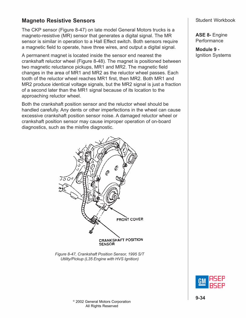
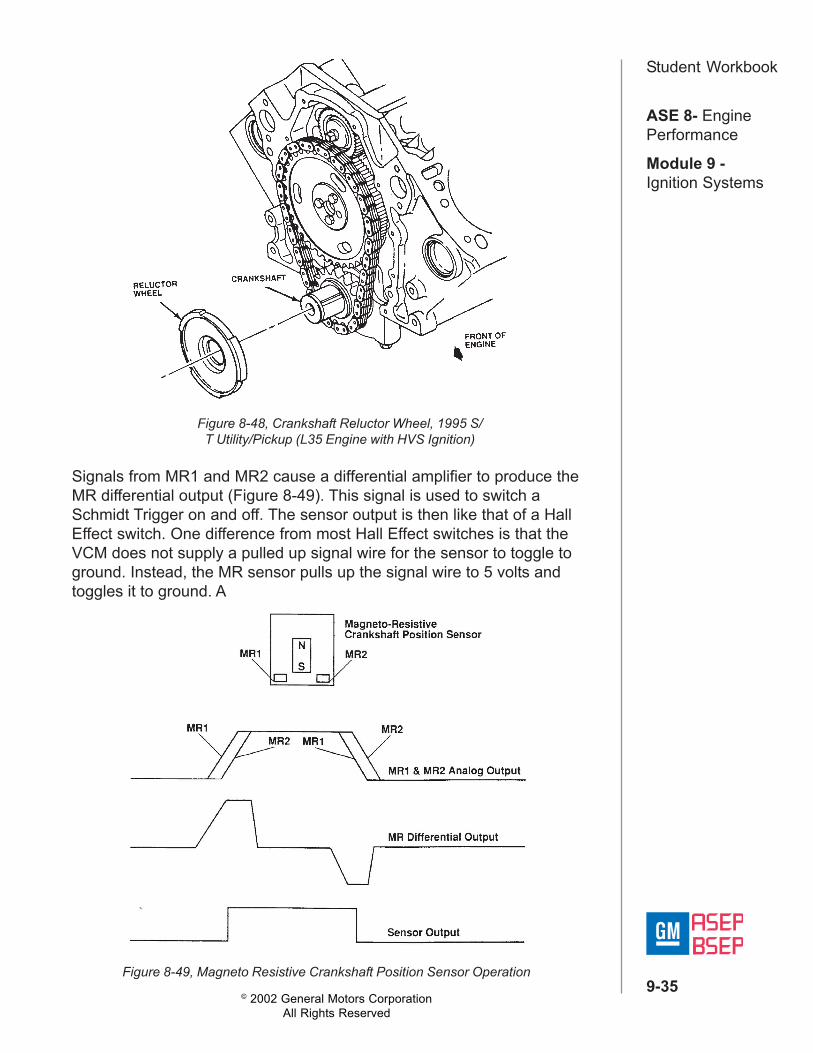
Student WorkbookMagneto Resistive SensorsThe CKP sensor (Figure 8-47) on late model General Motors trucks is amagneto-resistive (MR) sensor that generates a digital signal. The MRsensor is similar in operation to a Hall Effect switch. Both sensors requirea magnetic field to operate, have three wires, and output a digital signal.A permanent magnet is located inside the sensor end nearest thecrankshaft reluctor wheel (Figure 8-48). The magnet is positioned betweentwo magnetic reluctance pickups, MR1 and MR2. The magnetic fieldchanges in the area of MR1 and MR2 as the reluctor wheel passes. Eachtooth of the reluctor wheel reaches MR1 first, then MR2. Both MR1 andMR2 produce identical voltage signals, but the MR2 signal is just a fractionof a second later than the MR1 signal because of its location to theapproaching reluctor wheel.Both the crankshaft position sensor and the reluctor wheel should behandled carefully. Any dents or other imperfections in the wheel can causeexcessive crankshaft position sensor noise. A damaged reluctor wheel orcrankshaft position sensor may cause improper operation of on-boarddiagnostics, such as the misfire diagnostic.
Figure 8-47, Crankshaft Position Sensor, 1995 S/TUtility/Pickup (L35 Engine with HVS Ignition)
© 2002 General Motors CorporationAll Rights Reserved
ASE 8- EnginePerformance
Module 9 -Ignition Systems
9-35
Student Workbook
Signals from MR1 and MR2 cause a differential amplifier to produce theMR differential output (Figure 8-49). This signal is used to switch aSchmidt Trigger on and off. The sensor output is then like that of a HallEffect switch. One difference from most Hall Effect switches is that theVCM does not supply a pulled up signal wire for the sensor to toggle toground. Instead, the MR sensor pulls up the signal wire to 5 volts andtoggles it to ground. A
Figure 8-48, Crankshaft Reluctor Wheel, 1995 S/T Utility/Pickup (L35 Engine with HVS Ignition)
Figure 8-49, Magneto Resistive Crankshaft Position Sensor Operation

© 2002 General Motors CorporationAll Rights Reserved
ASE 8- EnginePerformance
Module 9 -Ignition Systems
9-36
Student Workbook
Figure 8-50, 6 Cylinder Cam and Crank Signals
HVS Distributor Ignition System OverviewThe ignition system used on late model truck applications, called the HVSDistributor Ignition System, features a high energy ignition coil and ignitioncoil driver module (Figure 8-51).Each engine application of this enhanced ignition system has a uniquedistributor.• 4.3L V6 non-adjustable• 6.0 and 5.7L V8 adjustable*• 7.4L V8 adjustable*
*Adjustable to eliminate the chance of crossfire only, not for timingadjustment.Trigger information for ignition timing is supplied by a Crankshaft Position(CKP) sensor. The CKP sensor is located in the timing chain cover. TheCMP sensor is located in the distributor base, and is used to sequence thefuel injectors and for on-board misfire diagnostics.
Figure 8-51, High Energy Ignition Coiland Driver Module
Figure 8-52, Truck Distributor
© 2002 General Motors CorporationAll Rights Reserved
ASE 8- EnginePerformance
Module 9 -Ignition Systems
9-37
Student WorkbookIgnition ControlThe High Voltage Switch distributor appears similar to a typical distributor,but key operational features make it very different (Figure 8-52). The HVSdistributor does not provide engine position information for spark delivery.Therefore, rotating the HVS distributor does not change ignition basetiming. The VCM contains the base timing information within its calibration.
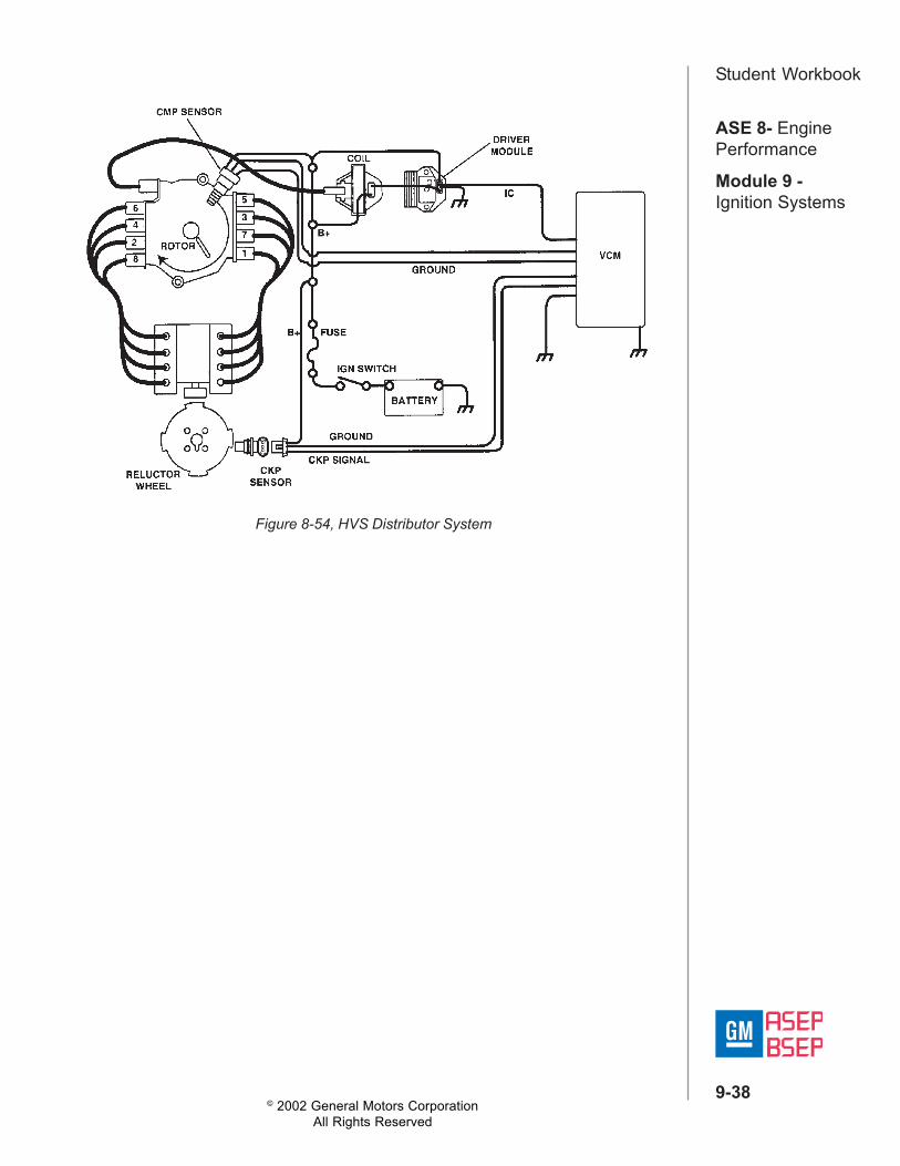
The ignition coil driver module is mounted with the high energy coil (Figure8-54). The Vehicle Control Module (VCM) controls the coil driver module.The coil driver module, in turn, controls current through the primarywinding of the coil. Note that the coil driver module has no backup(bypass) mode.Base timing is not adjustable because the crank sensor, not the distributor,determines base timing. This makes it the main sensor for fuel and spark.As a result, the engine will not run without a crankshaft position sensorsignal, because the ignition coil driver module doesn't have system triggerinformation. The crank sensor is located on the front of the engine in thetiming cover.The HVS Distributor Ignition system uses crankshaft and camshaftposition signals as inputs to the VCM. The VCM then uses the IgnitionControl (IC) circuit to signal the coil driver module to control spark timing(Figure 8-55):• The Crankshaft Position (CKP) sensor signal is used to determine
engine position and speed.• The Camshaft Position (CMP) sensor signal (.5X signal) identifies
piston position. The CMP sensor is used to sequence the fuel injectorsand detect misfire for OBD 11 diagnostics.
• The VCM uses the IC signal to control advance and retard based uponengine load, atmospheric pressure, rpm, and engine temperature.
Since the distributor has no influence on base timing, turning it will notmodify base timing in any way. However, the distributor on V8 applicationsis adjusted to eliminate the chance of crossfire at an adjacent terminal.Distributor terminal crossfire can be evident by poor performance, as thecontrol module will reduce the operating window for spark advance andretard.
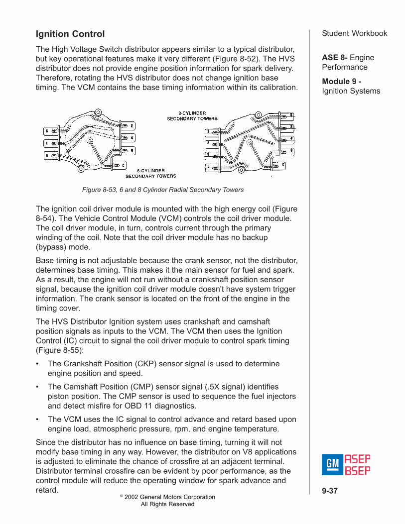
Figure 8-53, 6 and 8 Cylinder Radial Secondary Towers
© 2002 General Motors CorporationAll Rights Reserved
ASE 8- EnginePerformance
Module 9 -Ignition Systems
9-38
Student Workbook
Figure 8-54, HVS Distributor System

© 2002 General Motors CorporationAll Rights Reserved
ASE 8- EnginePerformance
Module 9 -Ignition Systems
9-39
Student Workbook
Figure 8-55, 4.3L Ignition System
© 2002 General Motors CorporationAll Rights Reserved
ASE 8- EnginePerformance
Module 9 -Ignition Systems
9-40
Student WorkbookCamshaft Retard Offset Adjustment (Truck V8)Test ProcedureThe ignition timing cannot be adjusted. The distributor may need adjustingto prevent crossfire. To ensure proper alignment of the distributor, performthe following:1. With the ignition OFF, install a scan tool to the DLC.2. Start the engine and bring to normal operating temperature.
3. Increase engine speed to 1 000 RPM4. Monitor the Cam Retard Offset.5. If the Cam Retard indicates a value of 0 ± 2, the distributor is properly
adjusted.6. If the Cam Retard does not indicate 0 ± 2, adjust the distributor.
Adjusting Procedure1. With the engine OFF, slightly loosen the distributor hold-down bolt.
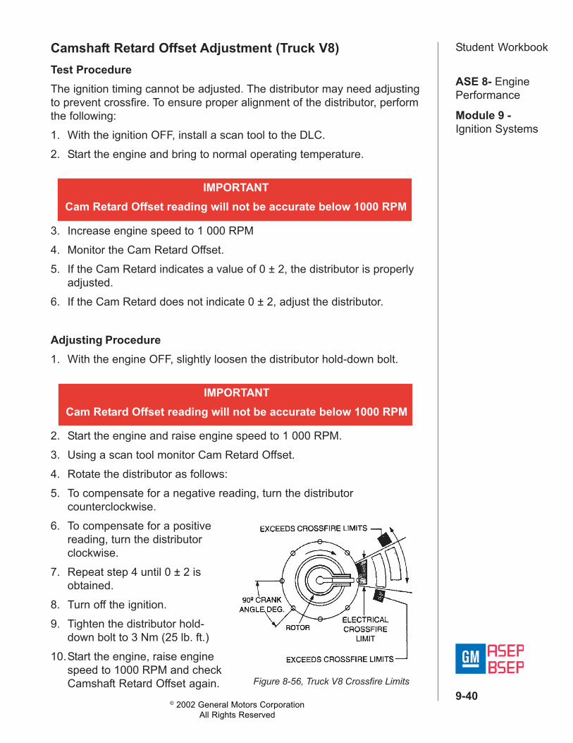
2. Start the engine and raise engine speed to 1 000 RPM.3. Using a scan tool monitor Cam Retard Offset.4. Rotate the distributor as follows:5. To compensate for a negative reading, turn the distributor
counterclockwise.6. To compensate for a positive
reading, turn the distributorclockwise.
7. Repeat step 4 until 0 ± 2 isobtained.
8. Turn off the ignition.9. Tighten the distributor hold-
down bolt to 3 Nm (25 lb. ft.)10.Start the engine, raise engine
speed to 1000 RPM and checkCamshaft Retard Offset again.
IMPORTANTCam Retard Offset reading will not be accurate below 1000 RPM
IMPORTANTCam Retard Offset reading will not be accurate below 1000 RPM
Figure 8-56, Truck V8 Crossfire Limits
© 2002 General Motors CorporationAll Rights Reserved
ASE 8- EnginePerformance
Module 9 -Ignition Systems
9-41
Student WorkbookCoil-Near-PlugAnother ignition system that uses a magneto resistive crankshaft positionsensor is the coil-near-plug system used on the LS1 engines starting in1997. The coil-near-plug system consists of the following components/circuits:• Eight Ignition Coils/Modules• Eight Ignition Control (IC) Circuits• Camshaft Position (CMP) Sensor• .5X Camshaft Reluctor Wheel• Crankshaft Position (CKP) Sensor• 24X Crankshaft Reluctor Wheel• Related Connecting Wires• Powertrain Control Module (POM)
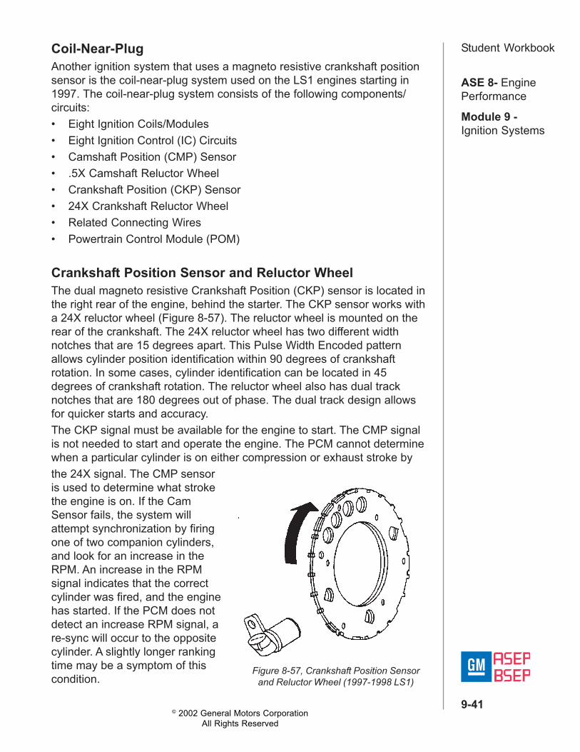
Crankshaft Position Sensor and Reluctor WheelThe dual magneto resistive Crankshaft Position (CKP) sensor is located inthe right rear of the engine, behind the starter. The CKP sensor works witha 24X reluctor wheel (Figure 8-57). The reluctor wheel is mounted on therear of the crankshaft. The 24X reluctor wheel has two different widthnotches that are 15 degrees apart. This Pulse Width Encoded patternallows cylinder position identification within 90 degrees of crankshaftrotation. In some cases, cylinder identification can be located in 45degrees of crankshaft rotation. The reluctor wheel also has dual tracknotches that are 180 degrees out of phase. The dual track design allowsfor quicker starts and accuracy.The CKP signal must be available for the engine to start. The CMP signalis not needed to start and operate the engine. The PCM cannot determinewhen a particular cylinder is on either compression or exhaust stroke bythe 24X signal. The CMP sensoris used to determine what strokethe engine is on. If the CamSensor fails, the system willattempt synchronization by firingone of two companion cylinders,and look for an increase in theRPM. An increase in the RPMsignal indicates that the correctcylinder was fired, and the enginehas started. If the PCM does notdetect an increase RPM signal, are-sync will occur to the oppositecylinder. A slightly longer rankingtime may be a symptom of thiscondition.
Figure 8-57, Crankshaft Position Sensorand Reluctor Wheel (1997-1998 LS1)
© 2002 General Motors CorporationAll Rights Reserved
ASE 8- EnginePerformance
Module 9 -Ignition Systems
9-42
Student Workbook
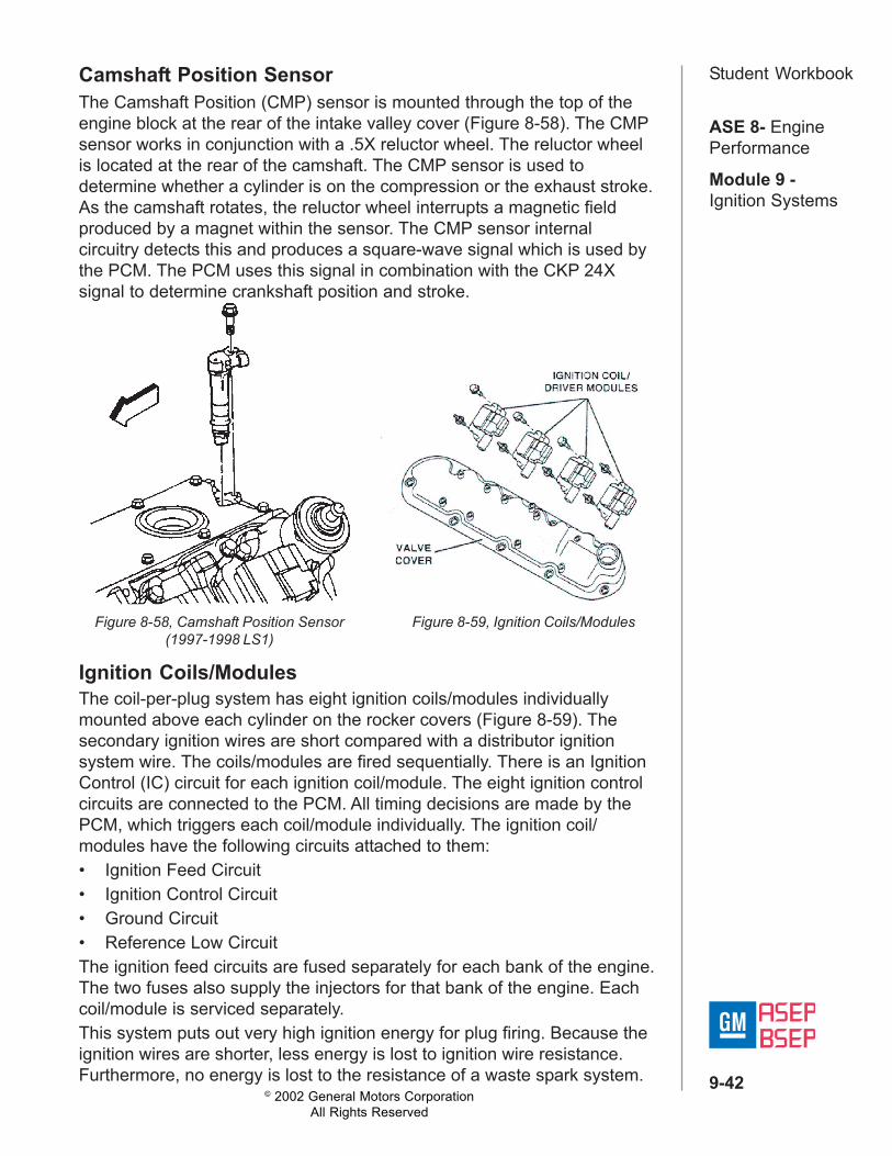
Figure 8-58, Camshaft Position Sensor(1997-1998 LS1)
Figure 8-59, Ignition Coils/Modules
Ignition Coils/ModulesThe coil-per-plug system has eight ignition coils/modules individuallymounted above each cylinder on the rocker covers (Figure 8-59). Thesecondary ignition wires are short compared with a distributor ignitionsystem wire. The coils/modules are fired sequentially. There is an IgnitionControl (IC) circuit for each ignition coil/module. The eight ignition controlcircuits are connected to the PCM. All timing decisions are made by thePCM, which triggers each coil/module individually. The ignition coil/modules have the following circuits attached to them:• Ignition Feed Circuit• Ignition Control Circuit• Ground Circuit• Reference Low CircuitThe ignition feed circuits are fused separately for each bank of the engine.The two fuses also supply the injectors for that bank of the engine. Eachcoil/module is serviced separately.This system puts out very high ignition energy for plug firing. Because theignition wires are shorter, less energy is lost to ignition wire resistance.Furthermore, no energy is lost to the resistance of a waste spark system.
Camshaft Position SensorThe Camshaft Position (CMP) sensor is mounted through the top of theengine block at the rear of the intake valley cover (Figure 8-58). The CMPsensor works in conjunction with a .5X reluctor wheel. The reluctor wheelis located at the rear of the camshaft. The CMP sensor is used todetermine whether a cylinder is on the compression or the exhaust stroke.As the camshaft rotates, the reluctor wheel interrupts a magnetic fieldproduced by a magnet within the sensor. The CMP sensor internalcircuitry detects this and produces a square-wave signal which is used bythe PCM. The PCM uses this signal in combination with the CKP 24Xsignal to determine crankshaft position and stroke.

© 2002 General Motors CorporationAll Rights Reserved
ASE 8- EnginePerformance
Module 9 -Ignition Systems
9-43
Student Workbook
Figure 8-60, LS1 Ignition Control ( 1 of 3)
© 2002 General Motors CorporationAll Rights Reserved
ASE 8- EnginePerformance
Module 9 -Ignition Systems
9-44
Student Workbook
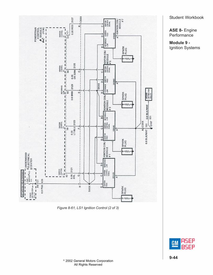
Figure 8-61, LS1 Ignition Control (2 of 3)
© 2002 General Motors CorporationAll Rights Reserved
ASE 8- EnginePerformance
Module 9 -Ignition Systems
9-45
Student Workbook
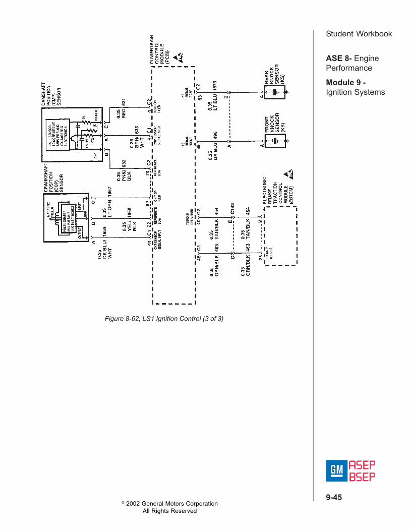
Figure 8-62, LS1 Ignition Control (3 of 3)

© 2002 General Motors CorporationAll Rights Reserved
ASE 8- EnginePerformance
Module 9 -Ignition Systems
9-46
Student WorkbookOptical Pick-Up SensorThe optical pick-up was first used in 1992 on the second generation smallblock V-8 engines, specifically the LTI 5.7L found in Corvettes, and later inother applications. The pick-up is part of the distributor assembly that islocated on the front of the engine, and is driven directly by the camshaft.The optical pick-up system provides actual crankshaft position, indegrees, to the PCM. This is possible by using a flat disk with two rows ofnotches cut around its circumference. One row has 360 notches, each 111wide, while the other row has eight notches. These eight notches arearranged with the following widths: 2°, 7°, 2°, 12°, 17°, 2°, 22° (Figure 8-63).
The optical sensor (Figure 8-64) uses an infrared light source andreceiver. When the camshaft turns, the optical pick-up produces two digitalsignals. The 360 notches produce a high resolution signal, while the eightnotches produce a low resolution signal. Both signals are sent directly tothe PCM, therefore, this is an up-integrated system with no bypass mode.The low resolution signal isused for rpm reference.Without the low resolutionsignal, there is no spark orfuel delivery. The highresolution signal is used tofine tune the engine'stiming, especially at higherrpm. The engine will startand run without the highresolution signal, but a longcrank complaint along withreduced performance couldbe noticed. The engine willnot run without the lowresolution signal present.
Figure 8-63, Optical Pick-Up Sensor Circuits and Signals
Figure 8-64, Optical Pick-Up Sensor

© 2002 General Motors CorporationAll Rights Reserved
ASE 8- EnginePerformance
Module 9 -Ignition Systems
9-47
Student WorkbookOpti-Spark Ignition SystemThe ignition system that uses the optical pick-up sensor is called Opti-Spark. Opti-Spark is a distributor ignition system that consists of thefollowing components (Figure 8-65):• Distributor housing• Cap and rotor• Optical position sensor• Sensor disc• Pickup assembly• Distributor Driveshaft
Figure 8-65, Opti-spark Distributor Assembly
© 2002 General Motors CorporationAll Rights Reserved
ASE 8- EnginePerformance
Module 9 -Ignition Systems
9-48
Student Workbook
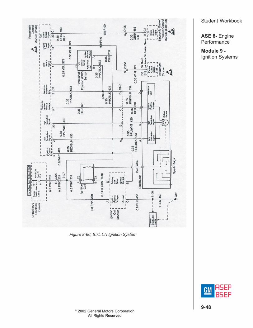
Figure 8-66, 5.7L LTI Ignition System

© 2002 General Motors CorporationAll Rights Reserved
ASE 8- EnginePerformance
Module 9 -Ignition Systems
9-49
Student WorkbookNoteworthy Ignition InformationThere are several important considerations to remember where servicingthe ignition system. The following list will help you in servicing the ignitionsystem.• The ignition coils secondary voltage output capabilities are very high -
more than 40,000 volts. Avoid body contact with ignition high voltagesecondary components when the engine is running, or personal injurymay result.
• The crankshaft position sensor is the most critical part of the ignitionsystem. If the sensor is damaged so that pulses are not generated, theengine will not start.
• Crankshaft position sensor clearance is very important. The sensormust not contact the rotating interrupter ring at any time, or sensordamage will result.
• Ignition timing is not adjustable. There are no timing marks on thecrankshaft balancer or timing chain cover.
• Be careful not to damage the secondary ignition wires or boots whenservicing the ignition system. Rotate each boot to dislodge it from theplug or coil tower before pulling it from either a spark plug or theignition coil. Never pierce a secondary ignition wire or boot for anytesting purposes. Future problems are guaranteed if test probes arepushed through the insulation for testing.
Diagnosing Ignition SystemsIgnition system malfunctions can be categorized as either misfire orincorrect timing. Each requires a different approach to repair. Oncediagnosis has lead to the ignition system, start looking for some telltalesigns of the problem. In the case of misfires, look for the following:• Plug wire disconnected• Carbon tracking on coils and plugs• Cracked insulators• Rubbing plug wires• Arcing to the block

© 2002 General Motors CorporationAll Rights Reserved
ASE 8- EnginePerformance
Module 9 -Ignition Systems
9-50
Student WorkbookListen for the snapping of a strayed spark to the block, or use the timetested procedure of spraying down the components with water in an effortto provide alternate ground paths. The use of an ignition scope can be avaluable source of information concerning the condition of the ignitionsystem.Misfires can occur at different times in the operation of the vehicle: all thetime, at idle only, and under load only. These are all clues as to thepossible source of the problem.Section 6 of the service manual usually includes a misfire detection chartthat tries to isolate the source of the misfire. Part of this chart requires theuse of an ST-125 that loads the ignition system by adding a specificresistance. It requires approximately 25kV to fire the ST-1 25. Therefore, ifthe coil can consistently fire the ST-1 25, the coil is functioning normally.Another way to load the ignition system would be to perform the followingCranking Ignition Load Test:
1. Disable fuel delivery.2. Set throttle to WOT.3. Crank engine (for no more than 15 seconds at one time).
Monitoring the ignition system on a scope while performing this test willshow coil output well above 30 kV. Any secondary malfunctions normallywill show up under these conditions.Incorrect timing typically is caused by an incorrect base timing setting. Butsystems such as the Knock Sensor (KS) circuit and some traction controlinputs can cause the timing to be incorrect as well. The computerassumes that base timing has been set correctly. Therefore, it controls thetiming assuming a proper starting point. If this is not the case, the timingthe computer wants, and the timing that the engine is running at can betwo different things. Of course, this is a moot point on El systems or "NetBuild" systems such as the Opti-Spark where there is no base timingadjustment.Incorrect timing can cause sluggish operation, pinging, poor gas mileage,overheating, and high exhaust emissions. Therefore, proper base timing iscritical.
© 2002 General Motors CorporationAll Rights Reserved
ASE 8- EnginePerformance
Module 9 -Ignition Systems
9-51
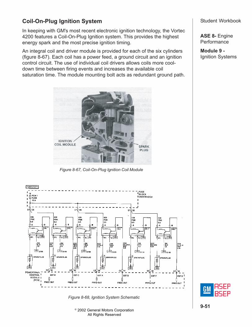
Student WorkbookCoil-On-Plug Ignition SystemIn keeping with GM's most recent electronic ignition technology, the Vortec4200 features a Coil-On-Plug Ignition system. This provides the highestenergy spark and the most precise ignition timing.An integral coil and driver module is provided for each of the six cylinders(figure 8-67). Each coil has a power feed, a ground circuit and an ignitioncontrol circuit. The use of individual coil drivers allows coils more cool-down time between firing events and increases the available coilsaturation time. The module mounting bolt acts as redundant ground path.
Figure 8-67, Coil-On-Plug Ignition Coil Module
Figure 8-68, Ignition System Schematic
© 2002 General Motors CorporationAll Rights Reserved
ASE 8- EnginePerformance
Module 9 -Ignition Systems
9-52
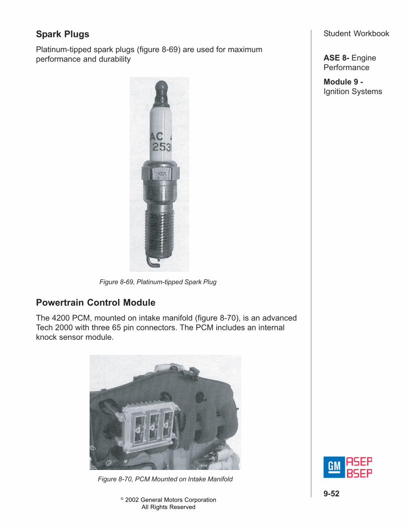
Student WorkbookSpark PlugsPlatinum-tipped spark plugs (figure 8-69) are used for maximumperformance and durability
Powertrain Control ModuleThe 4200 PCM, mounted on intake manifold (figure 8-70), is an advancedTech 2000 with three 65 pin connectors. The PCM includes an internalknock sensor module.
Figure 8-70, PCM Mounted on Intake Manifold
Figure 8-69, Platinum-tipped Spark Plug

© 2002 General Motors CorporationAll Rights Reserved
ASE 8- EnginePerformance
Module 9 -Ignition Systems
9-53
Student WorkbookDual Knock SensorsThe Vortec 4200 uses two knock sensors (figures 8-71 and 8-72) mountedat the front and rear on the intake side of the engine.
Figure 8-71, Dual Knock Sensors
Figure 8-72, Knock Sensor Wiring

© 2002 General Motors CorporationAll Rights Reserved
ASE 8- EnginePerformance
Module 9 -Ignition Systems
9-54
Student WorkbookCrankshaft Position (CKP) SensorAs with other ignition systems, the PCM uses crankshaft (CKP) andcamshaft position (CMP) sensors for precise ignition timing.The crankshaft position sensor is mounted in the left rear side of the block(figure 8-73). The reluctor wheel on the rear of the crankshaft has six,equally-spaced, notches and a synch notch.
Figure 8-73, CKP Sensor
Camshaft Position (CMP) SensorThe camshaft position sensor is mounted on the head, near the CamshaftPosition Actuator Solenoid Valve. The cam sensor reluctor ring is actuallypart of the hub of the Exhaust Camshaft Position Actuator.The camshaft position sensor sends position information to the PCMduring each revolution of the camshaft. Using the combined signals fromthe crankshaft and the camshaft position sensors, the PCM can determineengine position with great accuracy.If either the crankshaft or camshaft position sensor signal is lost for anyreason, the engine can run using the remaining signal alone. The MIL willilluminate to indicate that a DTC has set.
Figure 8-74, CMP Sensor