Embed Size (px)
Citation preview

ASE 8 - Engine Performance
Module 13Management System Diagnostics

AcknowledgementsGeneral Motors, the IAGMASEP Association Board of Directors, and Raytheon ProfessionalServices, GM's training partner for GM's Service Technical College wish to thank all of thepeople who contributed to the GM ASEP/BSEP curriculum development project 2002-3. Thisproject would not have been possible without the tireless efforts of many people. Weacknowledge:
• The IAGMASEP Association members for agreeing to tackle this large project tocreate the curriculum for the GM ASEP/BSEP schools.
• The IAGMASEP Curriculum team for leading the members to a single vision andimplementation.
• Direct contributors within Raytheon Professional Services for their support of translatinga good idea into reality. Specifically, we thank:
– Chris Mason and Vince Williams, for their leadership, guidance, and support.– Media and Graphics department under Mary McClain and in particular, Cheryl
Squicciarini, Diana Pajewski, Lesley McCowey, Jeremy Pawelek, & NancyDeSantis.
– For their help on the Engine Performance curriculum volume, Subject MatterExperts, John Beggs and Stephen Scrivner, for their wealth of knowledge.
Finally, we wish to recognize the individual instructors and staffs of the GM ASEP/BSEPColleges for their contribution for reformatting existing General Motors training material,adding critical technical content and the sharing of their expertise in the GM product. Separatecommittees worked on each of the eight curriculum areas. For the work on this volume, wethank the members of the Engine Performance committee:
– Jamie Decato, New Hampshire Community Technical College– Lorenza Dickerson, J. Sargeant Reynolds Community College– Marvin Johnson, Brookhaven College– Jeff Rehkopf, Florida Community College at Jacksonville– David Rodriguez, College of Southern Idaho– Paul Tucker, Brookdale Community College– Kelly Smith, University of Alaska– Ray Winiecki, Oklahoma State University - Okmulgee

ContentsModule 13 – Management System DiagnosticsAcknowledgements ......................................................................................... 2Introduction ...................................................................................................... 4Objectives ........................................................................................................ 6Overview .......................................................................................................... 7
Air Intake ......................................................................................................................... 7Fuel System..................................................................................................................... 8Ignition System .............................................................................................................. 14Next Steps ..................................................................................................................... 17Sensors ......................................................................................................................... 17Engine Mechanical Testing ............................................................................................ 22Manifold Vacuum Test .................................................................................................... 22Emission Systems ......................................................................................................... 26Strategy Based Diagnosis ............................................................................................. 29Application of SBD to Engine Performance ................................................................... 30Diagnostic Approach ..................................................................................................... 35Diagnostic Information and Procedures ......................................................................... 36

© 2002 General Motors CorporationAll Rights Reserved
ASE 8 - EnginePerformance
Module 13 -Managment SystemDiagnostics
13-4
Student WorkbookIntroductionNATEF TasksEngine PerformanceFor every task in Engine Performance the following safety requirement mustbe strictly enforced:Comply with personal and environmental safety practices associated withclothing; eye protection; hand tools; power equipment; proper ventilation; andthe handling, storage, and disposal of chemicals/materials in accordancewith local, state, and federal safety and environmental regulations.
A. General Engine Diagnosis1. Identify and interpret engine performance concern; determine
necessary action. P-12. Research applicable vehicle and service information, such as engine
management system operation, vehicle service history, serviceprecautions, and technical service bulletins. P-1
11. Diagnose engine mechanical, electrical, electronic, fuel, and ignitionconcerns with an oscilloscope and/or engine diagnostic equipment;determine necessary action. P-1
B. Computerized Engine Controls Diagnosis and Repair3. Diagnose the causes of emissions or driveability concerns resulting
from malfunctions in the computerized engine control system withstored diagnostic trouble codes. P-1
4. Diagnose emissions or driveability concerns resulting frommalfunctions in the computerized engine control system with no storeddiagnostic trouble codes; determine necessary action. P-1
9. Diagnose driveability and emissions problems resulting frommalfunctions of interrelated systems (cruise control, security alarms,suspension controls, traction controls, A/C, automatic transmissions,non-OEM-installed accessories, or similar systems); determinenecessary action. P-3
C. Ignition System Diagnosis and Repair1. Diagnose ignition system related problems such as no-starting, hard
starting, engine misfire, poor driveability, spark knock, power loss,poor mileage, and emissions concerns on vehicles with electronicignition (distributorless) systems; determine necessary action. P-1
2. Diagnose ignition system related problems such as no-starting, hardstarting, engine misfire, poor driveability, spark knock, power loss,poor mileage, and emissions concerns on vehicles with distributorignition (DI) systems; determine necessary action. P-1

© 2002 General Motors CorporationAll Rights Reserved
ASE 8 - EnginePerformance
Module 13 -Managment SystemDiagnostics
13-5
Student WorkbookD. Fuel, Air Induction, and Exhaust Systems Diagnosis and Repair1. Diagnose hot or cold no-starting, hard starting, poor driveability,
incorrect idle speed, poor idle, flooding, hesitation, surging, enginemisfire, power loss, stalling, poor mileage, dieseling, and emissionsproblems on vehicles with carburetor-type fuel systems; determinenecessary action. P-3
2. Diagnose hot or cold no-starting, hard starting, poor driveability,incorrect idle speed, poor idle, flooding, hesitation, surging, enginemisfire, power loss, stalling, poor mileage, dieseling, and emissionsproblems on vehicles with injection-type fuel systems; determinenecessary action. P-1
E. Emissions Control Systems Diagnosis and Repair1. Positive Crankcase Ventilation
Diagnose oil leaks, emissions, and driveability problems resultingfrom malfunctions in the positive crankcase ventilation (PCV) system;determine necessary action. P-2
2. Exhaust Gas RecirculationDiagnose emissions and driveability problems caused bymalfunctions in the exhaust gas recirculation (EGR) system;determine necessary action. P-1Inspect, test, service and replace components of the EGR system,including EGR tubing, exhaust passages, vacuum/pressure controls,filters and hoses; perform necessary action. P-2
3. Exhaust Gas TreatmentDiagnose emissions and driveability problems resulting frommalfunctions in the secondary air injection and catalytic convertersystems; determine necessary action. P-2
4. Intake Air Temperature ControlsDiagnose emissions and driveability problems resulting frommalfunctions in the intake air temperature control system; determinenecessary action. P-3
5. Early Fuel Evaporation (Intake Manifold Temperature) ControlsDiagnose emissions and driveability problems resulting frommalfunctions in the early fuel evaporation control system; determinenecessary action. P-3
6. Evaporative Emissions ControlsDiagnose emissions and driveability problems resulting frommalfunctions in the evaporative emissions control system; determinenecessary action. P-1

© 2002 General Motors CorporationAll Rights Reserved
ASE 8 - EnginePerformance
Module 13 -Managment SystemDiagnostics
13-6
Student WorkbookSTC Competencies
H. Strategy Based Diagnostics (SBD)1 Describe how to apply Strategy Based Diagnostics2 Descirbe how to verify the customer concern3 Describe how to conduct a visual inspection4 Explain how to research a vehicle using Service Bulletins and Vehicle
Service Records5 Describe how to perform diagnostic procedures6 Describe how to diagnose intermittent malfunctions7 Describe how to navigate service publications8 Identify possible causes of faulty DTCs
ObjectivesUpon successful completion of Engine Performance Module 13 Diagnosis,the ASEP student will be able to:• Apply Strategy Based Diagnostics• Describe Preliminary Checks• Describe Published Diagnostic System Checks• Explain bulletin search procedures• Explain Stored DTC diagnostic procedures• Explain Symptom No DTC diagnostic procedures• Explain No Published Diagnostic procedures• Describe Intermittent diagnostic procedures• Navigate Service Information (eSI)

© 2002 General Motors CorporationAll Rights Reserved
ASE 8 - EnginePerformance
Module 13 -Managment SystemDiagnostics
13-7
Student WorkbookOverviewAlthough the diagnostic path will be determined by the fault, there are someengine performance checks that can be performed. These are all fullysupported in the service information and are generally part of a diagnosticprocedure. The purpose of exploring these outside of the service proceduresis to provide an understanding of what they are and the information they willprovide.This module does not contain all the possible tests that are used to diagnoseengines and the sections on fuel and ignition do not apply to diesel engines.Diesel engines operate very differently from gas engines and modules areavailable that provide diagnostic approaches for diesel engines.
Air IntakeThe air intake system is essential for airflow into the engine. It has a systemof ductwork with an air filter to prevent debris from entering the engine. Mostnew vehicles will also have a mass air flow sensor located in the ductworkafter the air filter. If the air intake is damaged or restricted, it can preventsufficient airflow to the engine, reduce power and potentially cause a misfire.The following are the air intake system checks (figure 13-1): Air inlet forobstructions• Air filter for clogging• MAF sensor for debris• Air leaks after the MAF sensor• Damaged or restricted air ducts• Damaged or leaking air intake manifold• Missing, damaged or disconnected vacuum hosesMany of the newer air intake systemshave a restriction gauge, also knownas a change filter gauge. This can beused to initially check the system forpossible restrictions. However, makecertain that the gauge is reset beforetesting since the environment that itworks in can result in contamination.Reset the gauge and then restart theengine. Open the throttle severaltimes to place a vacuum on thesystem and then check the gauge.If the gauge indicates a restriction,check the filter. If the filter is good, then check the rest of the system forrestrictions.
Figure 13-1, Air Intake System (Typical)
© 2002 General Motors CorporationAll Rights Reserved
ASE 8 - EnginePerformance
Module 13 -Managment SystemDiagnostics
13-8
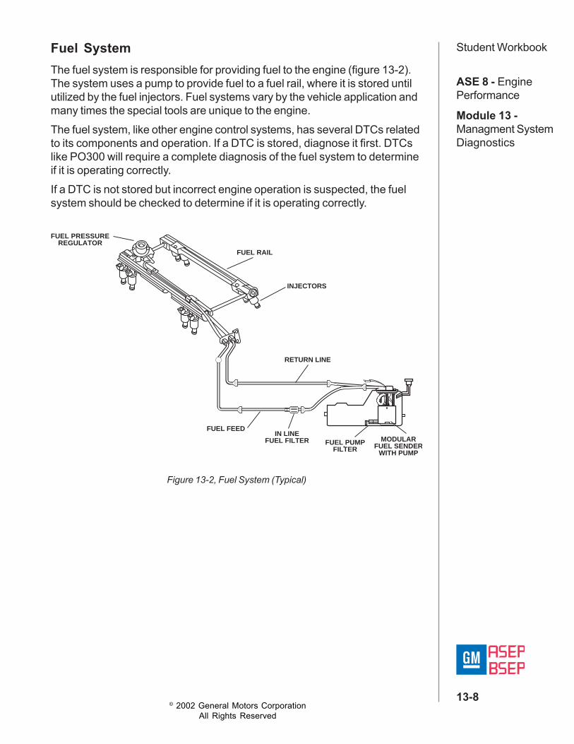
Student WorkbookFuel SystemThe fuel system is responsible for providing fuel to the engine (figure 13-2).The system uses a pump to provide fuel to a fuel rail, where it is stored untilutilized by the fuel injectors. Fuel systems vary by the vehicle application andmany times the special tools are unique to the engine.The fuel system, like other engine control systems, has several DTCs relatedto its components and operation. If a DTC is stored, diagnose it first. DTCslike PO300 will require a complete diagnosis of the fuel system to determineif it is operating correctly.If a DTC is not stored but incorrect engine operation is suspected, the fuelsystem should be checked to determine if it is operating correctly.
Figure 13-2, Fuel System (Typical)
FUEL PRESSURECONNECTION
RETURN LINE
IN LINEFUEL FILTER
FUEL FEED
FUEL PUMPFILTER
MODULARFUEL SENDER
WITH PUMP
FUEL RAIL
INJECTORS
FUEL PRESSUREREGULATOR

© 2002 General Motors CorporationAll Rights Reserved
ASE 8 - EnginePerformance
Module 13 -Managment SystemDiagnostics
13-9
Student WorkbookInjector Test LightWhen checking the fuelsystem start with the easiestthing first. Use an injector testlight (noid light) to see if theinjectors are firing. This tool isspecific to the engine andvehicle, and it is commonlyreferred to as a noid light(figure 13-3). The toolcontains an LED that will flashas the PCM provides pulsedpower on the injector circuit.The rate of flashing willincrease as the engine speedincreases.
If there is a fault, the light will either flash erratically or not flash. This isgenerally an indication of either a control circuit fault or PCM driver fault.Also remember, the PCM cannot control the fuel injection system correctly ifthe inputs are providing incorrect information. The primary inputs for fuelinjection are:• Manifold Absolute Pressure (MAP)sensor• Mass Air Flow (MAF) sensor• Throttle Position (TP) sensor• Accelerator Pedal Position (APP) sensor (if so equipped)• Crankshaft Position (CKP) sensor. Camshaft Position (CMP) sensor• Intake Air Temperature (IAT) sensor. Engine Coolant Temperature (ECT)
sensor• Oxygen (02) sensor (used during closed loop)There are additional inputs used for fuel control, but they are generally usedto fine-tune the basic control.
Figure 13-3, Injector Test Light

© 2002 General Motors CorporationAll Rights Reserved
ASE 8 - EnginePerformance
Module 13 -Managment SystemDiagnostics
13-10
Student WorkbookFuel Pressure TestingNext, check the fuel pressure. Thistest will help identify any leaks thatcould be resulting in fuel starvation.It will also indicate high pressure,which can result in excess fueldelivery and misfire. If excessive orinsufficient fuel delivery isidentified, there are special toolsavailable that can help isolate thesource (figures 13-4 and 13-5).Fuel pressure can be checked atthe fuel rail tap, using a fuel
pressure gauge and the appropriate adapter if necessary. The serviceinformation will contain specifications for the correct fuel pressure. Thediagnostics will generally check pressure build-up and pressure bleed downwith the fuel pump off. The system fuel pump should be able to rapidlypressurize the fuel rail to the specified range and then able to maintain thecorrect pressure when the pump is turned off.If initial checks indicate a malfunction, the fuel system shut-off tools must beused to isolate the source (figure 13-5). When the checks indicate a rail-mounted regulator malfunction, take the time to check the vacuum hoseconnected to the pressure regulator. It uses manifold vacuum to control thepressure of the fuel in the rail. Its hose must be connected and undamaged.Also check it for restrictions. It is also generally connected with a series ofother hoses. If these hoses are damaged or disconnected, the pressureregulator may not operate correctly. These checks do not apply to a"returnless" system, where the regulator is in the tank.
Figure 13-4, Fuel Pressure Gauge
Figure 13-5, Fuel System Schematic with Tools Installed
VACUUMLINE FUEL PRESSURE
GAUGE
FUELPRESSURE
REGULATOR FUELRAIL
FUELPUMP
FUELTANK
FUELFILTER
FUEL RAILINLET
FUEL INJECTORS
SUPPLY SHUTOFF(1/4 TURN VALVE)
RETURN LINESHUTOFF
(1/4 TURN VALVE)
FUEL RAILOUTLET

© 2002 General Motors CorporationAll Rights Reserved
ASE 8 - EnginePerformance
Module 13 -Managment SystemDiagnostics
13-11
Student Workbook
Fuel Trim and Oxygen Sensor ReadingsFuel trim numbers and oxygen sensor readings can also be very useful for anexperienced driveability technician, but they can be easily misinterpreted ifnot commonly used for diagnosis. In general, trim numbers (either negativeor positive) indicate that the PCM is trying to compensate for the operatingconditions. If the numbers are above +10% or below -10%, this can indicatea concern, but testing will be required to isolate the root cause.There are two types of fuel trim numbers: short term and long term (figure 13-8). These were once known as integrator and block learn, respectively.The short term fuel trim numbers control the fine-tuning of the fuel system, andit is normal for these numbers to fluctuate. If the short-term fuel trimadjustment cannot compensate for the engine operating conditions, the PCMwill adjust the long-term fuel trim. Short-term fuel trim only has a limitedamount of adjustment.Long-term fuel trim contains the learned information that the PCM uses toperform larger, more permanent, adjustments to fuel control (figure 13-9).These larger changes do not frequently fluctuate like short term.
Figure 13-8, Scan Tool Fuel Trim Numbers
Figure 13-9, Fuel Trim Percentages
GO LEANCOMMAND
GO RICHCOMMAND
NO ADJUSTMENT
0%
Percentage
Subtracting Fuel Adding Fuel
-100%
-80% -60% -40% -20% +20% +40% +60% +80%
+100%

© 2002 General Motors CorporationAll Rights Reserved
ASE 8 - EnginePerformance
Module 13 -Managment SystemDiagnostics
13-12
Student WorkbookIf the long-term fuel adjustment becomes too large, the PCM will store a DTCsince the system is operating outside of the normal parameters for fuelcontrol. This generally indicates either a concern in the fuel system or with theinputs used to control fuel. However, malfunctions that result in incorrectcombustion will also have a large effect on the fuel trim numbers since thePCM will try to compensate. Anything that causes the oxygen sensors toeither indicate an excessively lean or rich condition (even if it is false), willaffect the fuel trim numbers. This can include:• Engine mechanical concerns
– Low compression– Damaged spark plugs– Carbon deposits
• Exhaust concerns– Leaks– Incorrect air injection operation– Damaged 02 sensors
Oxygen (02) sensors are a major input for fuel control during closed loop(figure 13-10). Also with the introduction of OBD II, oxygen sensors are usedto monitor the efficiency of the catalytic converter. Oxygen sensors monitorthe amount of free oxygen in the exhaust stream. They do not measurerichness or leanness. However, the PCM uses this input to make an"educated guess" at what this input indicates about the conditions in thecombustion chamber.As long as every thing is operatingcorrectly, this "educated guess" is veryclose. However, if a malfunction (suchas a cracked exhaust manifold) occurs,the oxygen sensor can provide "false"information. It provides what it actuallysees, but due to the malfunction, it isnot an indication of what occurredduring combustion. This can result inincorrect control during closed loopoperation.
Figure 13-10, Oxygen SensorDesignation (V-8 Example)

© 2002 General Motors CorporationAll Rights Reserved
ASE 8 - EnginePerformance
Module 13 -Managment SystemDiagnostics
13-13
Student WorkbookOn OBD II-complaint vehicles, the pre-catalyst sensors can range between100 and 900 millivolts. However, the voltage fluctuations generally range fromapproximately 300 to 600 millivolts in closed loop with the engine operatingat a near ideal fuel ratio (stoichiometric). The post-catalyst sensors will bemuch flatter.An extended low voltage indicates a high amount of oxygen in the exhaustsystem, which is interpreted as a lean condition. An extended high voltageindicates a low amount of oxygen in the exhaust system, which is interpretedas a rich condition (figure 13-11).
0.30 v
0.45 v
0.60 v
0.45 v
0.60 v
0.45 v
0.60 v
NORMAL OPERATION
0.30 v
0.45 v
0.60 v
LEAN TOO LONG
0.30 v
RICH TOO LONG
0.30 v
BETWEEN 0.3–0.6 TOO LONG
Figure 13-11, Oxygen (02) Sensor Voltages

© 2002 General Motors CorporationAll Rights Reserved
ASE 8 - EnginePerformance
Module 13 -Managment SystemDiagnostics
13-14
Student WorkbookIgnition SystemThe ignition system is responsible for providing a spark for ignition. Thereare many different systems; however, most current ignition systems aredistributorless and have multiple ignition coils (figure 13-12).
The first basic test for the ignition system is the spark test. It uses the sparktester, which is a special tool (J 26792) and commonly called the ST-125(figure13-13). It connects to the spark plug wire and will provide a bright bluespark when the coil provides sufficient voltage. Some systems will requireadditional steps to use this tool since they do not use spark plug wires.If the tester does not provide a bright blue spark, the plug will not fire, andthere will be a misfire in that cylinder. Check the resistance of the plug wiresand then follow the service procedures to further diagnose the system.
Figure 13-12, Coil Near Plug Ignition System (GEN III)
Figure 13-13, Spark Tester (J 26792)

© 2002 General Motors CorporationAll Rights Reserved
ASE 8 - EnginePerformance
Module 13 -Managment SystemDiagnostics
13-15
Student WorkbookInsufficient spark or no spark can be the result of the following (figure 13-14):• Coil malfunction
– Open, short (to ground or across the coil) or high resistance in eitherthe secondary or primary
• Coil circuit– Carbon tracking on the coil or plug wire (providing a short to ground)
• Ignition Control Module (ICM) malfunction– Damaged internal circuits– Damaged circuits (wiring, connectors) between the ICM and PCM
• PCM malfunction– Internal malfunction– Incorrect inputs– Damaged control circuits (including terminals, connectors and wires) -
Calibration• Triggering circuit malfunctions
– CKP or circuit damage– CMP or circuit damage
If there is a good spark, the plug still needs to be checked since it may bedamaged (cracks, carbon tracking, etc.). Swapping plugs can be a usefulmethod to determine if the spark plug is damaged and inoperative. If a plugis damaged, it will generally create a misfire. When the spark plugs areswapped, the misfire should move with the plug. Also consider incorrectspark plugs if the concern occurs in multiple cylinders or is related to enginetemperature. This is because engines are designed to operate with sparkplugs that meet a specific heat range, have a specific gap and position thespark plug tip at the correct depth in the cylinder head.

© 2002 General Motors CorporationAll Rights Reserved
ASE 8 - EnginePerformance
Module 13 -Managment SystemDiagnostics
13-16
Student Workbook
UnderhoodAccessoryWiringJunctionBlock
Fire Order: 1 - 2 - 3 - 4 - 5 - 6
IC#2
IC#4
IC#6
6 4 2
Spark Plugs
IgnitionControl (IC)#2
IgnitionControl (IC)#4
IgnitionControl (IC)#6
Reference LO
GndRefLo
Ign1
Front BankIgnition
Control (IC)Module
Hot in RUN and START
F/INJRFUSE15 A#25
Also remember, a good spark doesn't indicate that the plug is being fired atthe correct time. Make sure plug wires are not crossed and that the engine isbeing fired in the correct order.
Figure 13-14, Ignition System Circuit

© 2002 General Motors CorporationAll Rights Reserved
ASE 8 - EnginePerformance
Module 13 -Managment SystemDiagnostics
13-17
Student WorkbookNext StepsIf the previous diagnostics do not isolate a fault, it's time to consider amechanical or emission system fault. There is also the possibility there is asensor fault that did not set a DTC. Sensor faults that cause engine concernsbut do not set DTCs should only be diagnosed by a driveability technician.Without proper training, these can be very difficult to isolate.
SensorsThe following are the primary sensors for engine control:• Mass Air Flow (MAF) sensor• Heated Oxygen Sensor (HO2S)• Throttle Position (TP) and/or Accelerator Pedal Position (APP) sensor• Engine Coolant Temperature (ECT) sensor• Intake Air Temperature (IAT) sensor• Manifold Absolute Pressure (MAP) sensor• Crankshaft Position (CKP) sensor• Camshaft Position (CMP) sensor• Knock sensor
These sensors provide signals to the PCM that help determine the engineoperating conditions and the control necessary for these conditions. All ofthese sensors have DTCs related to them, and on OBD II compliant vehicles,the PCM will often compare their input to other sensor values to determine ifthey are providing accurate information.However, some sensor faults may not produce a DTC. If this occurs, thePCM will not be aware that the sensor information is incorrect and engineperformance can be affected. The data list on the scan tool can be used tomonitor sensor input to the PCM and may indicate when a sensor isproviding incorrect information. Be cautious when using this information. Thedata list can be too slow to catch very transient (rapidly fluctuating) faults, andsometimes the data list displays a substitute value when the PCM detects afault. Also, you can use a known good vehicle to compare data values withthe suspect vehicle.

© 2002 General Motors CorporationAll Rights Reserved
ASE 8 - EnginePerformance
Module 13 -Managment SystemDiagnostics
13-18
Student WorkbookMAF SensorThe MAF sensor measures theamount of airflow into theengine. The measurement isprovided in grams per second(figure 13-15). The amount ofairflow considered normal willbe based on the engine, butairflow should be low at idle andincrease as the throttle plate isopened and the engine speedincreases.
Figure 13-15, MAF Sensor
Figure 13-16, Oxygen Sensors
MAF SENSOR
BANK 1SENSOR 1
BANK 1SENSOR 2
BANK 2SENSOR 1
BANK 2SENSOR 2
CONVERTERBANK 1
CONVERTERBANK 2
Oxygen SensorThe oxygen sensor provides information on the amount of oxygen in theexhaust system. Heated oxygen sensors have been used for several years toachieve reliable voltage output quicker. The oxygen sensors are used duringclosed loop operation, and their feedback is provided in millivolts. The pre-catalyst sensors should provide a voltage that fluctuates from approximately300 and 600 millivolts. Extended low voltage indicates a lean/high oxygencondition, and high voltage indicates a rich/low oxygen condition (figure 13-16). The post-catalyst sensor should provide a similar voltage range but willfluctuate much less.

© 2002 General Motors CorporationAll Rights Reserved
ASE 8 - EnginePerformance
Module 13 -Managment SystemDiagnostics
13-19
Student WorkbookTP and APP SensorsThe TP and APP sensors provide throttle plate angle and accelerator pedalposition. Both provide an input that is measured in voltage and will vary from0.25-5 volts (figure 13-17). The PCM can also provide data on the calculatedpercentage (0-100%) of angle. Tile APP and the "drive-by-wire" TP sensorsuse multiple potentiometers and will provide multiple inputs. The inputs willfollow different voltage ranges for the various positions of the throttle oraccelerator pedal.
Figure 13-17, TP and APP Circuit Schematic
5 V
0 V
0% PEDALTRAVEL
100% PEDALTRAVEL
1 V
2 V
3 V
4 V
APP SENSORSIGNAL #1
(0.67–2.51 VOLTS)
APP SENSORSIGNAL #2
(4.33–2.49 VOLTS)APP SENSOR
SIGNAL #3(4.00–2.88 VOLTS)
APP #1
APP #2
APP #3
5
4.5
4
3.5
3
2.5
2
1.5
1
0.5
00 10 20 30 40 50 60 70 80 90 100
PERCENT OF THROTTLE OPENING
SIG
NA
L V
OLT
AG
E
TP SENSOR #1TP SENSOR #2
TAC TP SENSOR SIGNAL VOLTAGES APP SENSOR SIGNALS
TP SENSOR#1
TP SENSOR#2
THROTTLEACTUATOR
CONTROL (TAC)MODULE
PCM
TP SENSOR
THROTTLE ACTUATORCONTROL (TAC) MOTOR
APP SENSOR

© 2002 General Motors CorporationAll Rights Reserved
ASE 8 - EnginePerformance
Module 13 -Managment SystemDiagnostics
13-20
Student WorkbookECT and IAT SensorsThe ECT/IA T are both thermistors that change resistance based ontemperature (figure 13-18). The resistance determines the voltage providedto the PCM. The PCM uses the voltage to calculate the temperature. ThePCM will display the calculated temperature on the data list. If the engine isat ambient temperature, the ECT and IAT inputs should both indicate atemperature near ambient.
Figure 13-19, MAP Sensor Circuit Schematic
Figure 13-18, ECT and IAT Sensor Circuit Schematic
B
A
3.65KΩ 348Ω
ECT SENSOR INPUT
5 VOLT REFABOVE 50° C
5 VOLT REFBELOW 50° C
ENGINE COOLANT MPERATURE SENSOR
MAP SensorThe MAP sensor measures the negative pressure (vacuum) in the intakemanifold and provides a voltage signal to the PCM (figure 13-19). The PCMuses this signal to calculate the pressure. The PCM can display theinformation from the MAP as either voltage or kilopascal (kpa). Kilopascalsare a metric measurement of pressure. Generally, it will vary from 20 to 48kPa (1.0-2.0V). At idle, the MAP reading should be low and increase as thethrottle angle increases.
SENSOR GROUND
+5V REFERENCE
MANIFOLD ABSOLUTEPRESSURE SENSOR SIGNAL
MAPSENSOR
A
B
C
PCM

© 2002 General Motors CorporationAll Rights Reserved
ASE 8 - EnginePerformance
Module 13 -Managment SystemDiagnostics
13-21
Student WorkbookCKP and CMP SensorsThe Camshaft (CMP) and Crankshaft Position (CKP) sensors are used todetermine engine speed and the location of the pistons in the four-strokecycle (figure 13-20). This is important information for sequential fuel controland for systems that use coil-on-plug spark control. The data for thesesensors will vary based on the type of sensor and the system. Refer to theservice information for the specific vehicle. It will provide the data availableand the normal range of operation. Some systems also have additionalinformation related to fuel and spark control resulting for the engine inputs.
Knock SensorThe knock sensor produces a voltage signal when an engine knock(detonation) is detected (figure 13-20). This signal is used to control sparktiming. If the PCM is detecting knock, it will adjust the spark timing, and thiswill be displayed as the knock retard. It can vary from 0-16 degrees. Somesystems will also display the knock sensor input on the data list.
Figure 13-20, CKP, CMP and Knock Sensor Circuit Schematic
MAGNETICPICKUP
CKP SENSORSIGNAL INPUT
CMP SENSORSIGNAL INPUT
KSSIGNALFRONT
KSSIGNALREAR
REFERENCELOW
REFERENCELOW
IGNITIONFEED
IGNITIONFEED
CRANKSHAFTPOSITION(CKP)SENSOR
A
0.31 YEL 573 0.35
0.35YEL/BLK
0.35PNK/BLK
0.35BRN/WHT
0.35DK BLU
FRONTKNOCKSENSOR(KS)
REARKNOCKSENSOR(KS)
0.35RED
LT GRN 1867
632
633
4960.35LT BLU 1876
631
44 C1 C14 4C2 C2
C2
22 62 70
69
A
A A
B
68
1868
B C
B
B A C C108
A C
CAMSHAFTPOSITION(CMP)SENSOR
POWERTRAINCONTROLMODULE(PCM)
OUTPUT INPUT
GND
GND POWER
29
1K47G
4700PF
PULSE SHAPERAND VOLTAGEREG ELECTRONICS
HALL SENSORTRIGGER CIRCUITAMPLIFIER ANDVOLTAGE REGELECTRONICS

© 2002 General Motors CorporationAll Rights Reserved
ASE 8 - EnginePerformance
Module 13 -Managment SystemDiagnostics
13-22
Student WorkbookEngine Mechanical TestingIf a mechanical fault is suspected, there are several tests that can be used toisolate it:• Manifold vacuum test• Compression test• Cylinder leakage test• Restricted exhaust test
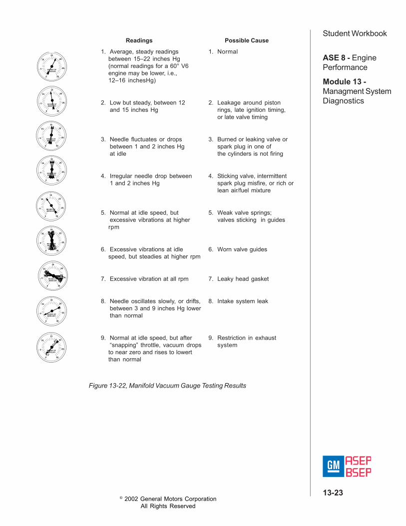
Manifold Vacuum TestThe manifold vacuum test uses a vacuum gauge to measure vacuum in theintake manifold (figure 13-21). This test can be used to determine the basiccondition of the engine when compared to vacuum charts (figure 13-22). Thistest is only a preliminary check for engine mechanical concerns since testingresults can be inconclusive due to intake manifold design, engine operationand location of vacuum tap.
Figure 13-21, Manifold Gauge Check
© 2002 General Motors CorporationAll Rights Reserved
ASE 8 - EnginePerformance
Module 13 -Managment SystemDiagnostics
13-23
Student Workbook
0
I
I
II
III
I
I
II
I
5
10
15
25
20
30
INCHES OFMERCURY
0
5
10
15
25
20
30
INCHES OFMERCURY
0
5
10
15
25
20
30
INCHES OFMERCURY
0
5
10
15
25
20
30
INCHES OFMERCURY
0
5
10
15
25
20
30
INCHES OFMERCURY
0
5
10
15
25
20
30
INCHES OFMERCURY
0
5
10
15
25
20
30
INCHES OFMERCURY
0
5
10
15
25
20
30
INCHES OFMERCURY
0
5
10
15
25
20
30
INCHES OFMERCURY
Figure 13-22, Manifold Vacuum Gauge Testing Results
Readings Possible Cause
1. Average, steady readings 1. Normalbetween 15–22 inches Hg(normal readings for a 60° V6engine may be lower, i.e.,12–16 inchesHg)
2. Low but steady, between 12 2. Leakage around pistonand 15 inches Hg rings, late ignition timing,
or late valve timing
3. Needle fluctuates or drops 3. Burned or leaking valve orbetween 1 and 2 inches Hg spark plug in one ofat idle the cylinders is not firing
4. Irregular needle drop between 4. Sticking valve, intermittent1 and 2 inches Hg spark plug misfire, or rich or
lean air/fuel mixture
5. Normal at idle speed, but 5. Weak valve springs;excessive vibrations at higher valves sticking in guidesrpm
6. Excessive vibrations at idle 6. Worn valve guidesspeed, but steadies at higher rpm
7. Excessive vibration at all rpm 7. Leaky head gasket
8. Needle oscillates slowly, or drifts, 8. Intake system leakbetween 3 and 9 inches Hg lowerthan normal
9. Normal at idle speed, but after 9. Restriction in exhaust“snapping” throttle, vacuum drops systemto near zero and rises to lowertthan normal

© 2002 General Motors CorporationAll Rights Reserved
ASE 8 - EnginePerformance
Module 13 -Managment SystemDiagnostics
13-24
Student WorkbookCompression TestThe static compression test is one of the best tests for engine mechanicalconcerns (figure 13-23). It tests the ability of the engine to draw-in air andcompress it. The test uses a compression gauge and requires the engine tobe cycled through four compression strokes (puffs) with all spark plugsremoved. The readings from all cylinders are compared against each otherand the minimum specification for the engine. Weak cylinders show-up asbelow the minimum specification or outside the range of the other cylinders.
A second version of the compression test is the running compression test. Itchecks the dynamic operation of the cylinder. This test is generally onlynecessary to identify cylinders with intermittent compression concerns (stickyvalves, bad valve guide, etc.).
Cylinder Leakage TestThe cylinder leakage test is used to isolate the source of a leak when acylinder has failed the compression test (figure 13-24). The tool for this testconnects to the spark plug hole and applies pressurized air to the cylinderwhen positioned at the compression stroke. With air applied, the leak can beisolated by checking for air at the tail pipe, oil fill tube, intake manifold andbubbles in the radiator.
Figure 13-23, Compression Testing
Figure 13-24, Cylinder Leakage Test

© 2002 General Motors CorporationAll Rights Reserved
ASE 8 - EnginePerformance
Module 13 -Managment SystemDiagnostics
13-25
Student Workbook
Figure 13-25, Restricted Exhaust Test
Restricted Exhaust TestThe last engine mechanical test is restricted exhaust (figure 13-25). Arestricted exhaust system can prevent the cylinder from completely expellingall the exhaust. This displaces the air/fuel mixture and can cause reducedpower, possible misfire or partial misfire. The restricted exhaust test uses apressure gauge to measure the amount of pressure in the exhaust systemduring both idle and at an elevated rpm (generally 2000 rpm). The pressureshould be at or below 2 psi. If it is above this, the exhaust system must beinspected for restrictions. It is possible on dual exhaust systems for only oneside to be restricted and only one bank of cylinders to be operatingabnormally.

© 2002 General Motors CorporationAll Rights Reserved
ASE 8 - EnginePerformance
Module 13 -Managment SystemDiagnostics
13-26
Student WorkbookEmission SystemsThe operation of the emission systems can have a large effect on theoperation of the engine when they are not operating correctly. The followingare the primary emission systems:• EGR• EVAP• Secondary Air Injection System• PCV
Exhaust Gas RecirculationThe EGR system is used to reduce emissions by allowing exhaust gases intothe combustion chambers (figures 13-26 and 13-27). Generally, the PCMcompensates for the operation of the EGR; however if it is malfunctioning, itcan produce a chuggle. A common concern with EGR valve is carbondeposits on the pintle valve, which allows exhaust gases into the intake.Since the valve is held open when the PCM is not commanding the EGRoperation, the PCM does not compensate for the mixture change and engineperformance is affected.
Figure 13-26, Linear EGR

© 2002 General Motors CorporationAll Rights Reserved
ASE 8 - EnginePerformance
Module 13 -Managment SystemDiagnostics
13-27
Student Workbook
Evaporative Emissions SystemThe EVAP system is used to direct evaporative emissions from the fuel tank(stored in the canister) into the intake for consumption by the engine (figure13-28). If this system allows evaporated fuel into the intake when the PCM isnot commanding it, the fuel ratio will be too rich. Check to make sure thepurge solenoid is closed until purge is commanded.
Figure 13-27, Linear EGR Circuit Schematic
LINEAREXHAUST GASRECIRCULATION(EGR)VALVE
5V
EGR5VREFERENCE
PWMEGRVALVECONTROL
POWERTRAINCONTROLMODULE(PCM)
EGR PINTLEPOSITIONSIGNAL
EGR SENSORGROUND
EGR VALVEGROUND
POWERTRAINCONTROLMODULE(PCM)
12V
Figure 13-28, EVAP System
FUEL LEVEL SENSOR
FUEL TANK PRESSURESENSOR
FUEL CAP
VAPOR
FUEL
VENT SOLENOID (NORMALLY OPEN)
FRE
SH
AIR
PCM
PURGE SOLENOID (NORMALLY CLOSED)
THROTTLE BODY
EVAPORATIVESYSTEM
CANISTER
SERVICE PORT

© 2002 General Motors CorporationAll Rights Reserved
ASE 8 - EnginePerformance
Module 13 -Managment SystemDiagnostics
13-28
Student WorkbookSecondary Air InjectionThe secondary air injection system uses an air pump to deliver fresh air intothe exhaust system (figure 13-29). This will increase the efficiency of thecatalytic converter. If this system operates when commanded off, the oxygensensors can detect a false lean condition and enrich the fuel. This can resultin a misfire due to excessive fuel. Check to see if the pump is running whencommanded off by the PCM.
Figure 13-29, Secondary Air Injection System
Figure 13-30, PCV System
Positive Crankcase VentilationThe PCV is used to direct crankcase gases into the intake manifold (figure13-30). If this valve malfunctions, excessive crankcase gases and oil can bedirected into the intake manifold. This can result in oil fouling, carbondeposits and misfires.
THROTTLE BODY FRESH AIR
PCV PIPEPCV VALVE
M
AIR PUMP
AIRSOLENOID
VACUUMHOSE
VACUUM OPERATEDSHUTOFF VALVE
CHECKVALVE
CHECKVALVE
© 2002 General Motors CorporationAll Rights Reserved
ASE 8 - EnginePerformance
Module 13 -Managment SystemDiagnostics
13-29
Student WorkbookStrategy Based DiagnosisAccurate diagnosis of any system fault requires an organized systematicapproach to your work. GM Strategy Based Diagnostics (SBD) provides theguidance to create such an approach for any diagnostic situation. The SBDprocess consist of three parts; the diagnostic thought process and problemsolving, the vehicle specific diagnostic flow chart which provides theapplication specific details, and the knowledge and experience of thetechnician.
Refer to eSI Document ID# 6856The goal of Strategy Based Diagnostics is to provide guidance when youcreate a plan of action for each specific diagnostic situation. Following asimilar plan for each diagnostic situation, you will achieve maximumefficiency when you diagnose and repair vehicles. Although each of theStrategy Based Diagnostics boxes is numbered, you are not required tocomplete every box in order to successfully diagnose a customer concern.The first step of your diagnostic process should always be, verify theCustomer Concern box. The final step of your diagnostic process should beRepair and verify the Fix box 7. Refer to the following chart for the correctStrategy Based Diagnostics.
(1) Verify the Customer Concern: The first part of this step is to obtain asmuch information as possible from the customer. Are thereaftermarket accessories on the vehicle? When does the conditionoccur? Where does the condition occur? How long does the conditionlast? How often does the condition occur? In order to verify theconcern, the technician should be familiar with the normal operation ofthe system and refer to the owner or service manual for anyinformation needed.
(2) Preliminary Checks: Conduct a thorough visual inspection. Review theservice history. Detect unusual sounds or odors. Gather diagnostictrouble code (DTC) information in order to achieve an effective repair.
(3) Perform Published Diagnostic System Checks: One or more DTCsmay not support a system. System checks verify the proper operationof the system. This will lead the technician in an organized approachto diagnostics.
(4) Check Bulletins and Other Service Information: Use videos,newsletters, and the Pulsat programs.
(5.1) Stored DTCs: Follow the designated DTC table exactly in order tomake an effective repair.
(5.2) Symptom No DTC: Select the symptom from the symptom tables.Follow the diagnostic steps or suggestions in order to complete therepair, or refer to the applicable component/system check.

© 2002 General Motors CorporationAll Rights Reserved
ASE 8 - EnginePerformance
Module 13 -Managment SystemDiagnostics
13-30
Student Workbook(5.3) No Published Diagnostics: Analyze the Concern. Develop a plan forthe diagnostics. The service manual schematics will help you to seesystem power, ground, and input and output circuits. You can alsoidentify splices and other areas where multiple circuits are tiedtogether. Look at component locations to see if components,connectors or harnesses may be exposed to extreme temperature,moisture, road salt or other corrosives battery acid, oil or other fluids.Utilize the wiring diagrams, system description and operation, andsystem circuit description.
(5.4) Intermittent: An intermittent condition is one that does not occurcontinuously and will occur when certain conditions are met. Generally,intermittents are caused by faulty electrical connections and wiring,malfunctioning components, electromagnetic/radio frequencyinterference, and aftermarket equipment. Combine technicianknowledge with efficient use of the available service information.Evaluate the symptoms and conditions described by the customer.Use a check sheet or other method in order to identify the component.Follow the suggestions for intermittent diagnosis found in the servicemanual. The Tech 1 and Tech 2 scan tools, and the J 39200 (Fluke 87)have data capturing capabilities that can assist in detection ofintermittents.
(5.5) Vehicle Operates as Designed: This condition exists when the vehicleis found to operate normally. The condition described by the customermay be normal. Verify against another like vehicle that is operatingnormally under the same conditions described by the customer.Explain your findings and the operation of that system to the customer.
(6) Re-examine the Concern: If a technician cannot successfully find orisolate the concern, a re-evaluation is necessary. Re-verify theconcern. The concern could be an intermittent or normal.
(7) Repair and Verify Fix: After isolating the cause, make the repairs andvalidate for proper operation. Verify that the symptom has beencorrected, which may involve road testing the vehicle.
Application of SBD to Engine PerformanceVerifying the Customer ConcernThe first step that you should always take when dealing with a customerconcern is to verify it. Sometimes a customer can mistake normal vehicleoperation for a problem. An example of this is the customer whose vehiclehas an Anti-Lock Brake System (ABS), and is concerned because of apulsating brake pedal during hard braking on ice or snow. Since manypeople are unaware of normal ABS operating characteristics during hardbraking, this customer has mistaken normal ABS operation for a malfunction.

© 2002 General Motors CorporationAll Rights Reserved
ASE 8 - EnginePerformance
Module 13 -Managment SystemDiagnostics
13-31
Student WorkbookIf you start diagnosing this vehicle for a problem when the vehicle isoperating normally, you're in for a long frustrating day.Another important aspect of verifying the customer concern is understandingthe issue. The average customer may not be very technically oriented.Customers may describe concerns in their own terms. An engine miss isoften described as "jerking" or "chugging". Some customers get detailedwhen describing a malfunction. They will throw in body gestures and evenmake faces and try to imitate vehicle noises. While sometimes this can behumorous to watch, what these people are trying to do is make sure youunderstand the vehicle symptoms.Always try to observe vehicle symptoms under the conditions the customersays they occur, such as vehicle temperature, loading, speed, etc.If you cannot verify the customer concern, consider taking the customer on aroad test with you. This ensures that the malfunction you are going todiagnose is the one with which the customer is concerned, is a truemalfunction, and not just a lack of understanding of normal vehicle operation).Few things are more frustrating for you and the customer than repairing asuspension noise in the front of the car when it was an engine noise thecustomer wanted fixed.
Visual InspectionYour visual inspection should initially focus on the system that you suspect isthe cause. An engine miss under load is not likely to be caused by adefective Idle Air Control (IAC) valve. Similarly, a hard starting engine is notlikely the result of a failed Vehicle Speed Sensor (VSS). A logical diagnosticstrategy includes first looking at the systems that are most likely to cause thecustomer concern.The visual inspection actually begins with the initial road test and continuesthrough the entire service procedure. During the initial road test, look for add-on electrical accessories such as car phones, alarms, radios, etc. Incorrectwiring of these accessories by unqualified personnel often causes vehiclemalfunctions. Another important inspection point, especially on ODB IIequipped vehicles, is the use of non-General Motors parts.Aftermarket catalytic converters and oxygen sensors often have differentoperating characteristics than genuine GM parts. This may cause the PCMto set a DTC because they don't work within the parameters of the PCM'sprogramming. This is not a quality issue, but a compatibility issue.
Important:Continue your visual inspection throughout the diagnosis and repairprocedure. Keep alert to indications of damaged components. Attention todetail when diagnosing and servicing vehicles is one of the best traits youcan develop.

© 2002 General Motors CorporationAll Rights Reserved
ASE 8 - EnginePerformance
Module 13 -Managment SystemDiagnostics
13-32
Student WorkbookChecking Service Bulletins and Vehicle Service RecordsThe use of service bulletins and vehicle service records should not beunderestimated. Sometimes a specific condition is common to a certainvehicle. If this is the case, there is likely to be a service bulletin issued aboutthe condition. The bulletin will also contain proven repair procedures that willsave you time when servicing the vehicle.Checking the vehicle records is also important. The vehicle records will tellyou if a customer's vehicle has previously been repaired for the sameconcern. This could indicate that the last repair cured only the symptom of thecondition instead of the cause. Or, it may indicate that the customer isoperating or maintaining the vehicle in some way that causes the condition toreoccur. Always ask the customer about any service that has been performedon the vehicle.
Performing Diagnostic ProceduresUsing the "right tool for the job" is important to automotive technicians. That'swhy most technicians invest thousands of dollars for the tools and equipmentneeded to service vehicles. Using the right diagnostic tools is equallyimportant. You can't replace a damaged or failed part unless you know whichone it is.When working with OBD II equipped vehicles, one of the most valuablediagnostic tools you have is the Tech 2. The tests it allows you to performprovide you with the information you need to take a wide range of symptomsand narrow them down to the specific area that is causing them.The data provided by Freeze Frame or Failure Records can be useful whentrying to determine the cause of a Diagnostic Trouble Code (DTC). Theserecords indicate what was occurring when the DTC was entered into thePCM's memory.For example, a vehicle comes in with engine miss. You can retrieve theFreeze Frame data to determine if the fuel trim was rich or lean, or what loadthe engine was under when the miss first occurred. This same type ofinformation is available on Failure Records, even for non-emission-relatedDTCs. This information will help you learn the conditions which were presentwhen the fault occurred, such as idle, low speed, high speed, high enginetemperature, etc., to allow you to efficiently diagnose the system.If more than one DTC is present, always correct the cause of a componentDTC before diagnosing any system DTCs. This is because a componentfault, such as a failed sensor, may cause a system diagnostic to fail. Oncethe failed component is replaced, the cause of the system DTC may becorrected, eliminating the need for further diagnosis.Also, when diagnosing an OBD II equipped vehicle, remember that a DTCcould be caused by the failure of a conventional component. For example, agradual failure of a fuel pump may cause a drop in fuel pressure which islarge enough to set a fuel trim DTC. Don't forget the basics because avehicle is OBD II equipped.

© 2002 General Motors CorporationAll Rights Reserved
ASE 8 - EnginePerformance
Module 13 -Managment SystemDiagnostics
13-33
Student WorkbookDiagnosing Intermittent MalfunctionsOf all the different types of conditions that you will see, the hardest toaccurately diagnose and repair are random and intermittent malfunctions.These conditions may be temperature related (only occur when the vehicle ishot or cold), or humidity related (only occur when it is raining). Regardless ofthe conditions that cause the malfunction to occur, you must diagnose andcorrect the condition.When dealing with an intermittent concern, you should determine theconditions when the malfunction occurs, and then try to duplicate thoseconditions. If a cause is not readily apparent to you, ask the customer whenthe symptom occurs. Ask if there are any conditions that seem to be relatedto, or cause the concern.Another consideration when working on an OBD II equipped vehicle iswhether a concern is random, intermittent, or occurs only when a specificdiagnostic test is performed by the PCM. Since OBD II systems conductdiagnostic tests only under very precise conditions, some tests may only berun once during an ignition cycle. Additionally, if the requirements needed toperform the test are not met, the test will not run during an ignition cycle. Thistype of on-board diagnostics could be mistaken as "intermittent" when, infact, the tests are only infrequent (depending on how the vehicle is driven).Examples of this type of diagnostic test are HO2S Heaters, EvaporativeCanister Purge, Catalyst Efficiency, and EGR Flow.
Important:When diagnosing intermittent concerns on an OBD II equipped vehicle,a logical diagnostic strategy is essential.Navigating Service PublicationsEarlier in this section we discussed the need for a logical diagnosticstrategy. Driveability complaints, which can be among the most difficult todiagnose, make a logical diagnostic strategy even more important. GeneralMotors Service Information (eSI) support Strategy Based Diagnostics byproviding you with logical strategies to help you diagnose customerconcerns.If a customer comes to you with a vehicle concern, but no DTC is in thePCM's memory, the first place to look for information on the symptom is inthe Engine Controls section of the Service Information.If a DTC is present in the PCM's memory, first move to the section whichcontains DTC diagnosis. The contents page has a list of the possible DTCsthat may be stored in the PCM's memory. Turn to the pages that describe thespecific diagnostic tests for the DTC you found.

© 2002 General Motors CorporationAll Rights Reserved
ASE 8 - EnginePerformance
Module 13 -Managment SystemDiagnostics
13-34
Student WorkbookOBD II provides the technician with more DTCs to help repair the vehicle.The DTC information has been reorganized in the service information. It isimportant (as it always has been) to be familiar with the DTC information andto use the added information to help during diagnostics. The DTCinformation is organized as follows:Circuit Description - This contains information about the normal operationand operating parameters of the system or components.Conditions for Setting the DTC (Conditions to Run for Cadillac) - Thislists the specific enable criteria as well as the exact conditions that causedthe DTC to set.Action Taken When the DTC Sets - This lists a description of what thePCM will do when the diagnostic test fails and the DTC is set.Conditions for Clearing the MIL/DTC - This lists the requirements to cleara DTC and what is required to turn off the MIL.Diagnostic Aids - Additional information that should be checked if thecondition is not resolved by following the diagnostic table.Diagnostic Table - This table tells you which diagnostic tests to perform andthe correct order in which to perform them. This diagnostic table has beenredesigned into five columns.The order in which DTCs are diagnosed has changed. The On-BoardSystem check will often help you determine which DTC to repair first. If theOBD system check does not direct you to the first DTC to diagnose,diagnose the DTCs in the following order:• PCM memory DTCs.• System voltage and Ignition voltage DTCs.• Component/circuit DTCs (sensors, etc.).• System DTCs (misfire, fuel trim, etc.).If more than one DTC is set in any group, diagnose DTCs from the lowestnumber to the highest.

© 2002 General Motors CorporationAll Rights Reserved
ASE 8 - EnginePerformance
Module 13 -Managment SystemDiagnostics
13-35
Student WorkbookDiagnostic ApproachStarting PointReference eSI Document ID# 661938Diagnostic Starting Point - Engine ControlsBegin the system diagnosis with Diagnostic System Check - EngineControls . The Diagnostic System Check-Engine Controls will provide thefollowing information:• The identification of the control modules which command the system• The ability of the control modules to communicate through the serial data
circuit• The identification of any stored diagnostic trouble codes (DTCs) and the
codes' statusesThe use of the Diagnostic System Check-Engine Controls will identify thecorrect procedure for diagnosing the system and where the procedure islocated.
Diagnostic System CheckReference eSI Document ID# 839781
DescriptionThe Diagnostic System Check-Engine Controls is an organized approach toidentifying a condition that is created by a malfunction in the powertraincontrol system. The Diagnostic System Check must be the starting point forany driveability concern. The Diagnostic System Check directs the servicetechnician to the next logical step in order to diagnose the concern.Understanding and correctly using the diagnostic table reduces diagnostictime, and prevents the replacement of good parts.

© 2002 General Motors CorporationAll Rights Reserved
ASE 8 - EnginePerformance
Module 13 -Managment SystemDiagnostics
13-36
Student WorkbookDiagnostic Information and ProceduresIn each of the diagnostic information and procedures menus the informationis list in the same sequence. This sequence is displayed in groups.The groups are the following:• Support Information• DTCs• Symptoms• SystemsThese groups allow the technician to quickly navigate through the content.
Support InformationThe first portion of the diagnostic information is not directed diagnostics butrather support material. In other words, the technician was not directed tothis document by another procedure. This information is used to help defineand/or assist with other procedures. The list below can be consideredsupport information.• Scan Tool Data List• Scan Tool Data Definitions• Scan Tool Output Controls - Engine Controls• Export Application Components Table• Diagnostic Trouble Code (DTC) List
DTC DiagnosisWith each new model year, the DTC list becomes longer and longer.Currently DTCs go far beyond the simple diagnosis of electrically controlledcomponent and circuit faults. PCMs are capable of providing diagnosis ofcomponents and systems that are not directly controlled by the PCM. MisfireDetection is only one of many examples of this type of diagnosis.
Symptoms DiagnosisThere are driveability concerns that the PCM is not capable of diagnosing.When this occurs, the technician will need to have a clearly defined symptomor symptoms and employ symptom diagnosis. Symptom diagnosis providessuggested components and systems that are related to the concern andpossible root causes of the fault.
Systems DiagnosisOccasionally diagnosis may isolate a concern to a system without the rootcause being found. Or, the diagnostics directs the technician to a systemdiagnostic procedure. Under these conditions, the technician will employsystem diagnosis. The approach of system diagnostics is that all of thesystem's functions, components and associated circuits are check for properoperation with the goal of isolating the root cause.