Embed Size (px)
Citation preview

ASE 8 - Engine Performance
Module 8Ignition Systems Triggering

AcknowledgementsGeneral Motors, the IAGMASEP Association Board of Directors, and RaytheonProfessional Services, GM's training partner for GM's Service Technical College wish tothank all of the people who contributed to the GM ASEP/BSEP curriculum developmentproject 2002-3. This project would not have been possible without the tireless efforts ofmany people. We acknowledge:
• The IAGMASEP Association members for agreeing to tackle this large project tocreate the curriculum for the GM ASEP/BSEP schools.
• The IAGMASEP Curriculum team for leading the members to a single vision andimplementation.
• Direct contributors within Raytheon Professional Services for their support oftranslating a good idea into reality. Specifically, we thank:
– Chris Mason and Vince Williams, for their leadership, guidance, and support.– Media and Graphics department under Mary McClain and in particular, Cheryl
Squicciarini, Diana Pajewski, Lesley McCowey, Jeremy Pawelek, & NancyDeSantis.
– For their help on the Engine Performance curriculum volume, Subject MatterExperts, John Beggs and Stephen Scrivner, for their wealth of knowledge.
Finally, we wish to recognize the individual instructors and staffs of the GM ASEP/BSEPColleges for their contribution for reformatting existing General Motors training material,adding critical technical content and the sharing of their expertise in the GM product.Separate committees worked on each of the eight curriculum areas. For the work on thisvolume, we thank the members of the Engine Performance committee:
– Jamie Decato, New Hampshire Community Technical College– Lorenza Dickerson, J. Sargeant Reynolds Community College– Marvin Johnson, Brookhaven College– Jeff Rehkopf, Florida Community College at Jacksonville– David Rodriguez, College of Southern Idaho– Paul Tucker, Brookdale Community College– Kelly Smith, University of Alaska– Ray Winiecki, Oklahoma State University - Okmulgee

ContentsModule 8 – Ignition Systems TriggeringAcknowledgements .......................................................................................... 2
Introduction ..................................................................................................................... 6Hall Effect ..................................................................................................................... 13Opti-Spark ..................................................................................................................... 15Magneto-Resistive Sensor ............................................................................................ 18Crankshaft Position Sensor (CKP)................................................................................ 20Camshaft Position Sensor (CMP) ................................................................................. 22Sensing Decode Mode.................................................................................................. 24CKP Sensor Variation Learn Process ........................................................................... 274.2L Ignition System Triggering..................................................................................... 28GEN III Coil-Near-Plug Ignition System Triggering ....................................................... 29Other GM Ignition Triggering Systems .......................................................................... 31Compression Sense Ignition System Triggering ........................................................... 37Distributor Ignition System Triggering ........................................................................... 42

© 2002 General Motors CorporationAll Rights Reserved
ASE 8 - EnginePerformance
Module 8 - IgnitionSystems Triggering
8-4
Student WorkbookNATEF Tasks1. Diagnose ignition system related problems such as no-starting, hard
starting, engine misfire, poor driveability, spark knock, power loss, poormileage, and emissions concerns on vehicles with electronic ignition(distributorless) systems; determine necessary action.
2. Diagnose ignition system related problems such as no-starting, hardstarting, engine misfire, poor driveability, spark knock, power loss, poormileage, and emissions concerns on vehicles with distributor ignition(DI) systems; determine necessary action.
3. Inspect and test ignition primary circuit wiring and solid statecomponents; perform necessary action.
4. Inspect and test ignition system secondary circuit wiring andcomponents; perform necessary action.
5. Inspect and test ignition coil(s); perform necessary action.6. Check and adjust ignition system timing and timing advance/retard
(where applicable).7. Inspect and test ignition system pick-up sensor or triggering devices;
perform necessary action
GM STC Tasks1. Identify the basic components of the ignition system2. Describe the basic operation of the ignition system3. Describe the operation of the ignition module4. Describe the operation of the IC circuit5. Describe the operation of the CKP sensor6. Identify the PCM inputs used for the ignition system control7. Describe the PCM outputs used for ignition control8. Identify the ignition components9. Identify ignition components differences between vehicle lines10.Identify the components of the C3I11. Describe the operation of the C3I12.Identify the components of the DIS13.Describe the operation of the DIS14.Identify the components of the HVS15.Describe the operation of the HVS16.Consult service information and interpret data

© 2002 General Motors CorporationAll Rights Reserved
ASE 8 - EnginePerformance
Module 8 - IgnitionSystems Triggering
8-5
Student Workbook17.Demonstrate use of the Tech 218.Interpret data related to Tech 2 usage19.Demonstrate the ability to use a DVOM and interpret data20.Diagnose electrical circuit concerns21.Follow service information and interpret data22.Demonstrate the ability to follow DTC codes and interpret data23.Follow vehicle service schematics and interpret data24.Demonstrate knowledge of the OBDII system25.Follow OBDII diagnosis charts and interpret data26.Demonstrate operational knowledge of vehicle fuel systems27.Diagnose concerns related to vehicle fuel systems28.Demonstrate operational knowledge of vehicle ignition systems29.Diagnose concerns related to vehicle ignition systems

© 2002 General Motors CorporationAll Rights Reserved
ASE 8 - EnginePerformance
Module 8 - IgnitionSystems Triggering
8-6
Student WorkbookIntroductionRegardless of the type, all ignition systems are made up of three sectionsor sub-groups; Primary, Triggering, and Secondary.
Figure 8-1, Ignition Systems

© 2002 General Motors CorporationAll Rights Reserved
ASE 8 - EnginePerformance
Module 8 - IgnitionSystems Triggering
8-7
Student WorkbookThe primary section of the ignition system includes all of the componentsand wires operating on low voltage 12 volts or system voltage. Theprimary circuit includes the ignition switch, coil primary windings, aswitching device ignition module, and all associated wires and connectors.
Figure 8-2, Primary Circuit
All ignition systems require a circuit to turn the current flow on and off inthe primary winding of the ignition coil. In the electronic ignition systemsused today, this is accomplished by a transistor in the ignition module. Thetriggering section is considered to be any form of signal that will providean input to the ignition module, or PCM, for switching of the coil.There are four categories of triggering devices: the Permanent Magnet(PM) Generator (also known as a Variable Reluctance Sensor), the HallEffect Switch, Optical Pickup, and Magneto Resistive (MR). Ignitionsystems using each type of these devices will be covered in detail in thissection.

© 2002 General Motors CorporationAll Rights Reserved
ASE 8 - EnginePerformance
Module 8 - IgnitionSystems Triggering
8-8
Student WorkbookThe Permanent Magnet, or PM, Generator, also known as a variablereluctant sensor, uses the principle of induction to develop an AC signal.In the sensor, a wire is coiled around a permanent magnet. By rotating areluctor, which has notches cut into it at precise locations, the magneticfield moves back and forth across the wire winding. This produces an ACvoltage signal in the wire.The ends of the wires are connected to either the Ignition Control Module,or ICM, or to the PCM.The signal is converted to the ON/OFF reference and used as the basetriggering for the primary circuit.
Figure 8-3, Permanent Magnet Generator

© 2002 General Motors CorporationAll Rights Reserved
ASE 8 - EnginePerformance
Module 8 - IgnitionSystems Triggering
8-9
Student WorkbookFor the Crankshaft Position Sensor to work, it must have a fifty-thousandths of an inch, plus or minus twenty-thousandths, of an air gapbetween the sensor and the reluctor.
Figure 8-4, Electronic Ignition
On Electronic Ignition, or EI systems,the sensor is mounted in the block orfront cover and is non-adjustable.
On vehicles with Distributor Ignition, or DI system, the pickup coil operatessimilarly. A magnet field increases and decreases as the teeth of the timercore and pole piece move in and out of alignment. This induces an ACflow through the pickup coil, which is the triggering signal to the ICM.
Figure 8-5, Distributor Ignition

© 2002 General Motors CorporationAll Rights Reserved
ASE 8 - EnginePerformance
Module 8 - IgnitionSystems Triggering
8-10
Student WorkbookEI Systems use a PM Generator and a reluctor that are part of theCrankshaft. The design of the Crankshaft reluctor is an importantconsideration when diagnosing these systems. Crankshaft reluctors onmost four and six-cylinder engines have seven notches. Each sendsvoltage signals to the ignition module for every revolution of theCrankshaft.Six of the notches are equally spaced at sixty-degree intervals around theCrankshaft. The seventh is positioned ten degrees from the sixth notch.The signal from the seventh or "sync" notch synchronizes the coil firingsequence with Crankshaft position. On four-cylinder engines, the ignitionmodule is programmed to recognize the "sync" notch, count notch numberone, and accept notch number two as the signal to fire the 2-3 companioncylinders. Next, the module counts notches three and four, then acceptsthe number five notch signal as the signal to fire the 1-4 cylinder pair. Thesixth and seventh notches are then counted and the process beginsagain.Note that the coil pack for the second cylinder in the firing order alwaysfires first during start up.On sixty-degree V6 engines, the Module skips the number one notch afterthe sync signal and fires the 2-5 cylinders on the signal from notch 2.Notch 3 is skipped and notch 4 fires the 3-6 cylinder pair. Finally, notch 6is used to fire the 1-4 pair.
Figure 8-6, Crankshaft Reluctor

© 2002 General Motors CorporationAll Rights Reserved
ASE 8 - EnginePerformance
Module 8 - IgnitionSystems Triggering
8-11
Student WorkbookPM Generator output voltage varies with engine speed. Typical valuesrange from approximately five-hundred millivolts at cranking speeds toone-hundred volts at high RPM, depending on the application. Whenmeasuring the output from a magnetic crank sensor, the voltmeter shouldbe set on an appropriate AC scale.The output from a P M Generator and a given engine, will vary basedupon:• Cranking speed,• The air gap of the sensor to the reluctor,• The resistance of the sensor windings,• The temperature of the sensor, and• The strength of the magnet.
Figure 8-7, P-M Generator
It is also important to know if the circuit you are diagnosing is a Pull-Upcircuit or a Pull-Down circuit, especially in an ignition system.Always refer to the appropriate service information electrical schematicswhen performing diagnosis on ignition systems.

© 2002 General Motors CorporationAll Rights Reserved
ASE 8 - EnginePerformance
Module 8 - IgnitionSystems Triggering
8-12
Student WorkbookA Pull-Up circuit has a power source outside the PCM. The PCM does notprovide the reference voltage signal. When the switch is closed, externalsource voltage provides a high reference signal to the PCM. An openswitch, on the other hand, provides a low reference signal.
Figure 8-8, Pull-Up Circuit
A Pull-Down circuit is provided with a reference voltage signal from thePCM. The power source for the circuit is internal to the PCM.When the switch is closed, source voltage is pulled low to an externalground. The PCM registers a low voltage reference signal.When the switch is open, the PCM registers a high reference signal.
Figure 8-9, Pull-Down Circuit

© 2002 General Motors CorporationAll Rights Reserved
ASE 8 - EnginePerformance
Module 8 - IgnitionSystems Triggering
8-13
Student WorkbookHall EffectNow let's look at another ignition triggering device, the Hall Effect switch.The Hall Effect Switch is used on several ignition system applications. TheHall Effect Switch is an electronic device that produces a voltage signalcontrolled by the presence or absence of a magnetic field in an electroniccircuit.When a magnetic field is introduced perpendicular to a current flowingthrough a semiconductor, a measurable voltage is induced at the sides ofthe semiconductor, at right angles to the main current flow. This is knownas the Hall Effect.A regulated signal voltage from the ignition module is passed through asemiconductor wafer in the Hall Switch.A permanent magnet mounted beside the semiconductor induces Hallvoltage across the semiconductor.The crank sensor is positioned so that metal blades, or "vanes", of aninterrupter ring mounted on the crankshaft harmonic balancer damperpass between the semiconductor and the permanent magnet.The Hall voltage is amplified and routed to the base of a transistor, whichcontrols the ground on the signal voltage from the ignition module.
Figure 8-10, The Hall Effect Switch
When the metal vane is outside the sensor, the transistor is ON and thesignal from the module is grounded.

© 2002 General Motors CorporationAll Rights Reserved
ASE 8 - EnginePerformance
Module 8 - IgnitionSystems Triggering
8-14
Student Workbook
Figure 8-11,
When a metal vane comes between the magnet and the semiconductor,the magnetic field is interrupted and the Hall voltage drops off.The Hall voltage drops when the vane is inside the sensor, and thetransistor turns OFF and the signal returns to the high state. As theinterrupter rotates, signal voltage alternates between high and low states,generating a square-wave with the same pattern as on the interruptervanes.Note that the module supply voltage is pulled low by the sensor.

© 2002 General Motors CorporationAll Rights Reserved
ASE 8 - EnginePerformance
Module 8 - IgnitionSystems Triggering
8-15
Student WorkbookOpti-SparkNow let's look at a triggering system based on the use of an optical pick-up. This was first used in 1992 on the second generation small block V8engines, specifically the LT 1 five point seven liter found in Corvettes andlater in other applications.The ignition system that uses the optical pick-up sensor is called Opti-Spark. Opti-Spark is a distributor ignition system that consists of thefollowing components:• The Distributor Housing• A Cap and Rotor• The Optical Position Sensor• A Sensor Disk• The Pickup Assembly• The Distributor Drive Shaft
Figure 8-12, Opti-Spark

© 2002 General Motors CorporationAll Rights Reserved
ASE 8 - EnginePerformance
Module 8 - IgnitionSystems Triggering
8-16
Student WorkbookThe Pick-Up is part of the distributor assembly that is located on the frontof the engine and is driven directly by the camshaft. The Optical Pick-UpSystem provides actual crankshaft position in degrees to the PCM. This ispossible by using a flat disk with two rows of notches cut around itscircumference.
Figure 8-13, Optical Pick-Up System
One row has three hundred and sixty notches, each one degree wide.The other row has eight notches. These eight notches are arranged withthe following widths:• 2 degree, 7 degree• 2 degree, 12 degree• 2 degree, 17 degree• 2 degree, 22 degree
The Optical sensor uses an infrared light source and receiver.

© 2002 General Motors CorporationAll Rights Reserved
ASE 8 - EnginePerformance
Module 8 - IgnitionSystems Triggering
8-17
Student WorkbookWhen the camshaft turns, the Optical Pick-Up produces two digitalsignals. The 360 notches produce a high-resolution signal, while the8 notches produce a low-resolution signal.
Figure 8-14, Optical Pick-Up Signal
Both signals are sent directly to the PCM; therefore, this is an up-integrated system with no bypass mode.The low-resolution signal is used for RPM reference. Without the low-resolution signal, there is no spark or fuel delivery. The high-resolutionsignal is used to fine-tune the engine's timing, especially at higher RPMs.The engine will start and run without the high-resolution signal, but a longcrank complaint, along with reduced performance, could be noticed. Theengine will not run without the low-resolution signal present.

© 2002 General Motors CorporationAll Rights Reserved
ASE 8 - EnginePerformance
Module 8 - IgnitionSystems Triggering
8-18
Student WorkbookMagneto-Resistive SensorA Magneto-Resistive, or MR, Crankshaft Position Sensor is used on someGeneral Motor trucks. This sensor generates a digital signal. The MRSensor is similar in operation to a Hall Effect Switch. Both sensors requirea magnetic field to operate, have three wires and produce a digital outputsignal.A permanent magnet is located inside the sensor end nearest theCrankshaft Reluctor Wheel.
Figure 8-15, Magneto-Resistive Sensor

© 2002 General Motors CorporationAll Rights Reserved
ASE 8 - EnginePerformance
Module 8 - IgnitionSystems Triggering
8-19
Student WorkbookThe magnet is positioned between two magnetic reluctance pick ups, MR1and MR2. The magnetic field changes in the area of MR1 and MR2 as theReluctor Wheel passes. Each tooth of the Reluctor Wheel reaches MR 1before MR2.Both MR1 and MR2 produce identical voltage signals, but the MR2 signalis just a fraction of a second later than the MR1 signal because of itslocation to the approaching Reluctor Wheel.
Figure 8-16, MR1/MR2 Voltage Signals
Both the Crankshaft Position Sensor and Reluctor Wheel should behandled carefully. Any dents or other imperfections in the wheel can causeexcessive Crankshaft Position sensor noise. A damaged Reluctor Wheelor Crankshaft Position Sensor may cause improper operation of on-boarddiagnostics, such as the misfire diagnostics.Signals from MR and MR2 cause a differential amplifier to produce theMR differential output. This signal is used to switch a Schmidt Trigger onand off.A Schmidt trigger is a two-state device used to square-up waveforms withslow rise and fall times. Digital circuits prefer wave forms with fast rise andfall times, and uneven waveforms can distort data if fed directly into adigital circuit. The Schmidt trigger converts these erratic signals intosquare waves.The sensor output is then like that of a Hall Effect Switch. One differencefrom most Hall Effect Switches is that the VCM does not supply a pulledup signal wire for the sensor to toggle to ground. Instead, the MR sensorpulls the signal up to five volts and toggles it to ground.

© 2002 General Motors CorporationAll Rights Reserved
ASE 8 - EnginePerformance
Module 8 - IgnitionSystems Triggering
8-20
Student WorkbookCrankshaft Position Sensor (CKP)The three point five liter LX5 engine uses a single crankshaft position, orCKP, sensor located in the left side of the engine block behind the startermotor. The air gap between the CKP and the reluctor wheel is notadjustable.
Figure 8-17, Crankshaft Position Sensor (CKP)
The CKP sensor operates on the Magneto-Resistive principle and isactually two sensors within a single housing. The sensors are called CKPSensor A and CKP Sensor B.
Figure 8-18, CKP Sensor A and B
The CKP sensor connector contains six terminals to provide power,reference low, and signal circuit connections between the PCM and theCKP Sensors A and B.
Figure 8-19, CKP Sensor Connector

© 2002 General Motors CorporationAll Rights Reserved
ASE 8 - EnginePerformance
Module 8 - IgnitionSystems Triggering
8-21
Student WorkbookThe four point six liter L D 8/L 37 engines use two separate CKP sensors.The CKP sensors operate on the Magneto- Resistive principle. Thesensors are called CKP A and CKP B. They are located in the left side ofthe engine block and have a non-adjustable air gap.
Figure 8-20, CKP A and CKP B Sensors
The CKP connectors are keyed to prevent plugging the CKP harnessconnector into the wrong sensor. However, nothing prevents a technicianfrom installing the CKP sensors into the wrong holes.Because the CKP sensors have angled ends, improper installation willresult in damage to the CKP sensor. Do not over torque the CKP sensorsor damage will occur.The PCM can use two different modes of decoding crankshaft positionsensor pulses. During normal operation, it performs an angle-baseddecode operation using both signals.
Figure 8-21, Crankshaft Position Sensor Pulses
© 2002 General Motors CorporationAll Rights Reserved
ASE 8 - EnginePerformance
Module 8 - IgnitionSystems Triggering
8-22
Student WorkbookThe engine will continue to operate even if one signal is lost. If thishappens, the PCM will use a time-based decode mode.The two sensors, reading the reluctor wheel in the crankshaft, allow thePCM to perform an angle-based decode operation.This is considered a self-clocked system, where one sensor acts as aclock and the other is a data signal.The advantage of angle-based decoding is the increased accuracy andconsistency of signals, even during engine acceleration and deceleration.If one sensor is not operating correctly, the PCM will use a time-baseddecode operation. A time-based decode operation will read the pulsewidth of one signal.Since no clock signal is available, time-based decoding is not as accurateduring engine acceleration and deceleration.
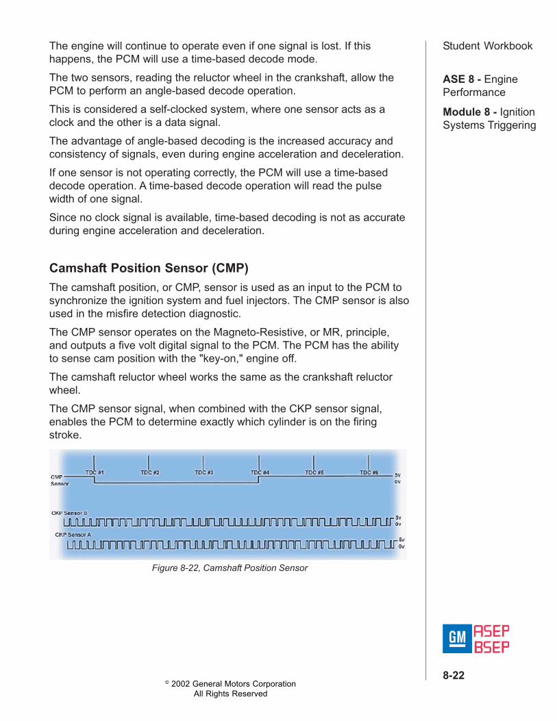
The camshaft position, or CMP, sensor is used as an input to the PCM tosynchronize the ignition system and fuel injectors. The CMP sensor is alsoused in the misfire detection diagnostic.The CMP sensor operates on the Magneto-Resistive, or MR, principle,and outputs a five volt digital signal to the PCM. The PCM has the abilityto sense cam position with the "key-on," engine off.The camshaft reluctor wheel works the same as the crankshaft reluctorwheel.The CMP sensor signal, when combined with the CKP sensor signal,enables the PCM to determine exactly which cylinder is on the firingstroke.
Camshaft Position Sensor (CMP)
Figure 8-22, Camshaft Position Sensor

© 2002 General Motors CorporationAll Rights Reserved
ASE 8 - EnginePerformance
Module 8 - IgnitionSystems Triggering
8-23
Student WorkbookThe CMP sensor signal is toggled by the track on the cam sprocket/reluctor wheel.
Figure 8-23, CMP Sensor Reluctor Track
Using the CMP and the CKP sensors, the PCM can determine engineposition in six CKP sensor pulses, within ninety degrees.If the CMP signal is absent during engine cranking, there is a fifty percentchance of it starting immediately. The CKP sensor will indicate which twocylinders are at top dead center, but the PCM does not know whichcylinder is on the compression and which one is on the exhaust stroke.The PCM will fire one of the cylinders. If an increase in RPM is detected,the correct cylinder was fired and the engine will run. If the correct cylinderwas not fired on the first attempt, cranking time will be longer than normal.The three point five liter, LX5 CKP Sensors A and B have separate power,ground, and signal circuits.
Figure 8-24, LX5 CKP Sensors A and B
© 2002 General Motors CorporationAll Rights Reserved
ASE 8 - EnginePerformance
Module 8 - IgnitionSystems Triggering
8-24
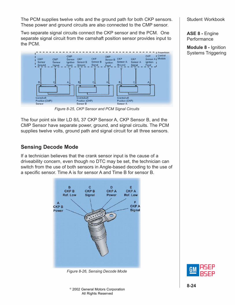
Student WorkbookThe PCM supplies twelve volts and the ground path for both CKP sensors.These power and ground circuits are also connected to the CMP sensor.Two separate signal circuits connect the CKP sensor and the PCM. Oneseparate signal circuit from the camshaft position sensor provides input tothe PCM.
Figure 8-25, CKP Sensor and PCM Signal Circuits
The four point six liter LD 8/L 37 CKP Sensor A, CKP Sensor B, and theCMP Sensor have separate power, ground, and signal circuits. The PCMsupplies twelve volts, ground path and signal circuit for all three sensors.
Sensing Decode ModeIf a technician believes that the crank sensor input is the cause of adriveability concern, even though no DTC may be set, the technician canswitch from the use of both sensors in Angle-based decoding to the use ofa specific sensor. Time A is for sensor A and Time B for sensor B.
Figure 8-26, Sensing Decode Mode

© 2002 General Motors CorporationAll Rights Reserved
ASE 8 - EnginePerformance
Module 8 - IgnitionSystems Triggering
8-25
Student WorkbookThis eliminates the suspect sensor signal from the PCM for that ignitioncycle.In the CKP decode mode the test can be run only one time per ignitioncycle.In this mode the CKP Sensor Status data parameter displays the actualPCM operating mode.
Figure 8-27, CKP Sensor Status Data Parameter
The PCM's 24 X crank sensor data must read "0" before making acommand. This is accomplished with the engine not running.All DTCs must be cleared at this time. Keep in mind that even if theTech 2 is disconnected, the PCM will retain the command state for theentire key cycle.

© 2002 General Motors CorporationAll Rights Reserved
ASE 8 - EnginePerformance
Module 8 - IgnitionSystems Triggering
8-26
Student Workbook
Figure 8-28, Decode Mode Test
To begin the decode mode test, choose Powertrain Special Functions,Engine Output Controls, then Crank Position Sensing Decode Mode.
Press the select state soft key until the desired state is displayed: time A,time B, or Angle. For this example, time A was chosen.Before starting the engine, press the command state soft key.Start the engine and monitor the CKP sensor status data parameter.Confirm that the CKP sensor status matches what you just selected.If the driveability concern is no longer present while performing this test,CKP Sensor B has a fault.
Figure 8-29, State Soft Key

© 2002 General Motors CorporationAll Rights Reserved
ASE 8 - EnginePerformance
Module 8 - IgnitionSystems Triggering
8-27
Student Workbook
Figure 8-30, Diagnostic Trouble Code P1336
CKP Sensor Variation Learn ProcessThe CKP Sensor Variation Learn Procedure eliminates unwanted misfireDTCs caused by tolerances in crank sensingcomponents. CKP Sensor Variation LearnProcedure needs to be performed if theDiagnostic Trouble Code P1336 is set, or whenreplacing the PCM, engine crankshaft, or CKPSensor.
The following steps are used when performing the CKP Sensor VariationLearn Procedure. To prevent personal injury to you and others, begin theCKP Sensor Variation Learn Procedure by:• Closing the hood,• Setting the parking brake, and• Blocking the drive wheels.Once the safety steps have been completed, allow the engine to run untilit reaches operating temperature, then turn off the engine, and turn thekey to run.Next, select and enable the CKP Sensor System Variation LearnProcedure from the Tech 2, and start the engine.At this time, you'll apply the brake pedal firmly. When the transaxle is inpark, rapidly increase accelerator pedal position until it reaches the fuelcutoff. The CKP Sensor Variation compensating values are learned whilethe engine RPM lowers to an idle. Observe the DTC status for DTCP1336. If the Scan tool indicates DTC P1336 the system variation has notbeen learned, and the Variation Learn Procedure MUST be performed.The Scan Tool CKP Sensor Variation Learn Procedure will be inhibited ifcoolant temperature is less than one-hundred fifty eight degreesFahrenheit or seventy degrees Celsius. Allow the engine to run until itreaches operating temperature.The Variation Learn Procedure will also be inhibited, if any PowertrainDTCs are set before or during the CKP Procedure.Serious engine damage may occur if the throttle is not released as soonas fuel cutoff is reached. When the CKP Sensor Variation LearnProcedure is complete, the PCM has learned sufficient data to preventunwanted misfire DTCs from setting due to tolerances in crank sensingcomponents.

© 2002 General Motors CorporationAll Rights Reserved
ASE 8 - EnginePerformance
Module 8 - IgnitionSystems Triggering
8-28
Student Workbook4.2L Ignition System TriggeringThe four point two liter ignition system is a coil-per-plug system that iscontrolled by the PCM There are some differences between the four pointtwo coil per plug system and others.
Figure 8-31, 4.2L Ignition System Triggering
The CKP sensor in this system is a permanent magnet generator, knownas a variable reluctance sensor. The magnetic field is altered by acrankshaft mounted reluctor wheel that has seven machined slots, six ofwhich are equally spaced sixty degrees apart. The seventh slot is spacedten degrees after one of the sixty degree slots, and is the sync pulse. TheCKP sensor signal is received by the PCM.This CMP sensor is triggered by a notched reluctor wheel built into theexhaust camshaft sprocket. The CMP sensor provides six signal pulsesevery camshaft revolution.
Figure 8-32, CMP Sensor
Each notch or feature of the reluctor wheel is of a different size forindividual cylinder identification. This means the CMP and CKP signalsare pulse width encoded to enable the PCM to constantly monitor theirrelationship. This relationship is used to determine camshaft actuatorposition and control it's phasing at the correct value. The PCM also usesthis signal to identify the compression stroke of each cylinder, and forsequential fuel injection.

© 2002 General Motors CorporationAll Rights Reserved
ASE 8 - EnginePerformance
Module 8 - IgnitionSystems Triggering
8-29
Student WorkbookGEN III Coil-Near-Plug Ignition System TriggeringThe Gen 3 V-8 small block engines use a coil-near-plug ignition system. This system consistsof 8 coil module driver assemblies, located onthe valve covers, which are attached to thespark plugs with spark plug wires.This engine uses a Camshaft Position Sensor,and a Crankshaft Position Sensor.Ignition timing is dependent on both the CMPsensor and the CKP Sensor.While the crankshaft position sensor identifiescylinder pairs at top dead center, the CMPsensor identifies the cylinder stroke, eithercompression or exhaust. Figure 8-33, GEN III Coil-Near-Plug
Ignition System
The PCM uses the Camshaft Position Sensorinformation to determine whether a cylinder ison a firing or exhaust stroke.A1 X reluctor wheel, machined as part of thecamshaft, interrupts a magnetic field producedby a magnet within the CMP sensor as thecamshaft rotates.
Figure 8-34, A1 X Reluctor Wheel
The CMP sensor's internal circuitry detectsthis and produces a signal that the PCMreads.The 24 X Crankshaft Position Sensor CKPSensor is the most critical input for theignition system. If the sensor is damaged sothat pulses are not generated, the enginewill not start.
Figure 8-35, 24 X CrankshaftPosition Sensor

© 2002 General Motors CorporationAll Rights Reserved
ASE 8 - EnginePerformance
Module 8 - IgnitionSystems Triggering
8-30
Student WorkbookCKP sensor to Reluctor clearance is also very important. The sensor mustnot contact the rotating reluctor ring at any time, or sensor damage willresult.The CKP sensor is found on the right lower rear of the engine block,behind the starter.The sensor reads a reluctor wheel on the crankshaft to identify cylinderpairs at top dead center.
Figure 8-36, CKP Reluctor Wheel
The CKP reluctor wheel uses twenty four notches of two different widths,positioned every fifteen degrees. This pulse width encoded pattern allowspiston position identification within ninety degrees of crank rotation.The reluctor is heated, indexed, and pressed onto the crankshaft duringmanufacture. The reluctor must be serviced along with the crankshaft.

© 2002 General Motors CorporationAll Rights Reserved
ASE 8 - EnginePerformance
Module 8 - IgnitionSystems Triggering
8-31
Student WorkbookOther GM Ignition Triggering SystemsLet's look at how the 4.0 and 4.6 liter Direct Ignition System is triggered.The four point oh and four point six liter V 8 Direct Ignition System is awaste spark system that has dual variable reluctance crankshaft sensors,with one reluctor ring to monitor crankshaft position.The reluctor ring has twenty-four evenly spaced notches and eightunevenly spaced notches.
Figure 8-37, Direct Ignition System
With the "B" sensor mounted twenty-seven degrees of crankshaftrevolution behind the "A" sensor, a unique pattern of pulses is created thatallows the ignition to synchronize and fire the first coil in less than one halfor one hundred eighty degrees crankshaft revolution.The Ignition Module accomplishes this by monitoring the pulses it receivesfrom each Crankshaft Position Sensor.The Ignition Module counts the number of "B" pulses between "A" pulses.The pattern on the reluctor ring allows either zero, one or two "B's"between "A's." When the Module recognizes one or four patterns of B'sbetween A's, the Crankshaft Position is known and the ignition system issynchronized.The ignition can synchronize at four different crankshaft positions;therefore, the first cylinder fired at engine start-up will depend on where orwhat position the engine stopped at previous Key OFF. The system alsouses a magnetic Camshaft Position Sensor for fuel control and misfirediagnostics.Now let's look the triggering system used on GM (C3I ) equipped vehicles,found on the 3.0 and 3.8 liter engines.

© 2002 General Motors CorporationAll Rights Reserved
ASE 8 - EnginePerformance
Module 8 - IgnitionSystems Triggering
8-32
Student WorkbookThis system has Hall Effect switches for crank and cam position with acrank sensor interrupter ring mounted on the back side of the harmonicbalancer. In addition, there is an ignition module and a coil pack assembly.
Figure 8-38, Coil Packs
There are two coil pack designs, Type 1 and Type 2, which areinterchangeable on some models.A variation to this system, known as the Fast Start, uses a uniqueinterrupter ring, which gives more precise crank information. This systemprovides faster starts by supplying information for correct cylinder firingwithout relying on the cam signal.The CKP sensor on the 3.0 liter engine is located adjacent to thecrankshaft harmonic damper.

© 2002 General Motors CorporationAll Rights Reserved
ASE 8 - EnginePerformance
Module 8 - IgnitionSystems Triggering
8-33
Student WorkbookTwo concentric rings on the back of the damper pass on each side of theHall Effect magnet. The inner ring has three evenly spaced vanes andwindows, which send identically timed signals of the same duration. Theouter ring has only one window. This single pulse acts as the synchronizesignal to set up the logic for triggering the correct ignition coil.
Figure 8-39,
On the three point eight liter SFI and SFI turbo engines, the synchronizesignal is determined by a separate camshaft sensor. The magnet ismounted in the camshaft sprocket.The cam sensor signal identifies cylinder sequence for injector firing on asequential fuel injector system as well as the sync signal for the ignitionmodule.

© 2002 General Motors CorporationAll Rights Reserved
ASE 8 - EnginePerformance
Module 8 - IgnitionSystems Triggering
8-34
Student WorkbookThe C3 I Fast Start system on the thirty-eight-hundred and 1993 thirty-three-hundred engines use a dual crankshaft sensor and a separate camsensor.Advantages of the Fast Start system are: faster start-up, walk-homeprotection in the event of cam sensor malfunction, and more precisemeasurement of crankshaft sensor signals.
On Fast Start systems, the dual crank sensor is mounted on the front ofthe engine beside the harmonic balancer, crankshaft pulley. The CMPsensor is mounted on the timing cover beside the cam sprocket.The arrangement of the interrupter rings on the harmonic balancer isdifferent than on the other V 6 engines. The outside ring has eighteenevenly sized and evenly spaced interrupter blades to produce eighteenpulses per crankshaft revolution. These pulses are known as the 18 Xsignal.The inside ring has three interrupter blades with gaps, or windows, of 10,20, and 30 degrees. These gaps, in turn, are spaced 100, 90, and 100degrees apart respectively. These pulses are referred to as the 3 X signal. With this interrupter ring arrangement, the ignition module can identify theproper cylinder pair to fire within as little as one-hundred-twenty degreesof crankshaft rotation.The module can also fire any cylinder pair reaching TDC first withoutwaiting for the cam or sync signal.
Figure 8-40, C31 Fast Start System

© 2002 General Motors CorporationAll Rights Reserved
ASE 8 - EnginePerformance
Module 8 - IgnitionSystems Triggering
8-35
Student WorkbookFor Crankshaft Sensor Adjustment on the 3300 and 3800 V6s, useadjusting tool part number J-37089 to ensure accurate positioning of thesensor, and to maintain proper clearance between the interrupter vanesand the sensor.
The tool is also used to check interrupter rings for out-of-round. Be sure tofollow the procedures listed in current maintenance information whenusing adjusting tool J-37089.The tool can be used to adjust all crankshaft sensors, with the exceptionof the Delco single-slot design sensor and late model thirty-eight-hundreds.The single slot design crankshaft sensors are adjusted using the Kent-Moore feeler gage style adjusting tool, J-36179.
Figure 8-41, Crankshaft Sensor Adjustment
Figure 8-42, Single Slot Crankshaft Sensors

© 2002 General Motors CorporationAll Rights Reserved
ASE 8 - EnginePerformance
Module 8 - IgnitionSystems Triggering
8-36
Student WorkbookThe 31000 and 3400 Ignition System is a hybrid ignition system that usestwo crankshaft position sensors. The 24 X Hall switch CKP signal is adirect input to the PCM, while the 7 X, a permanent magnet style CKPsignal, is an input to the Ignition Control Module.
Figure 8-43, 3100 & 3400 Ignition System
The ignition control module sends a 3 X signal to the PCM. The 3 X signalis a condition signal sent by the Ignition Control Module based on the 7 XCKP signal.Below 1200 RPM, the PCM controls ignition timing and idle speed usingthe CKP 24 X signal.The PCM uses the 3 X signal from the Ignition Control Module to calculateengine speed and crankshaft position over 1200 RPM. If the PCMreceives no pulses on this circuit, DTC P1374 sets and the PCM uses the24 X reference signal circuit for fuel and ignition control.
Figure 8-44,

© 2002 General Motors CorporationAll Rights Reserved
ASE 8 - EnginePerformance
Module 8 - IgnitionSystems Triggering
8-37
Student WorkbookThe CMP sensor sends a cam position signal tothe PCM, which uses it as a sync pulse totrigger the injectors in proper sequence. ThePCM uses the CMP signal to indicate theposition of the number one piston during itsintake stroke. This allows the PCM to calculatea true sequential fuel injection mode ofoperation.If the PCM detects an incorrect CMP signalwhile the engine is running, DTC P0341 sets.If the CMP signal is lost while the engine isrunning, the fuel injection system shifts to acalculated sequential fuel injection mode basedon the last fuel injection pulse and the enginecontinues to run.The engine can be restarted and run in a calculated sequential mode aslong as the fault is present with a 1 in 6 chance of injector sequence beingcorrect.
Compression Sense Ignition System TriggeringThe two point two liter engine, RPO code L 61, uses a waste sparkelectronic ignition system.
Figure 8-45,
Figure 8-46,

© 2002 General Motors CorporationAll Rights Reserved
ASE 8 - EnginePerformance
Module 8 - IgnitionSystems Triggering
8-38
Student WorkbookAlthough waste spark ignition is familiar technology, the L 61 ignitionsystem is referred to as the Compression Sense Ignition, or CSI.CSI enables the PCM to determine proper engine phasing without the useof a separate camshaft position sensor.CSI's modular design is similar to the ignition systems used on thepremium V 6 and V 8 engines. Both systems house nearly all the majorignition system components in a single cassette, although only the L 61engine uses compression sense.The ignition cassette is mounted directly over the spark plugs, requiringonly a connector spring and insulating boot to transfer the ignition energyto the spark plugs. The cassette houses two ignition coils. Each coil sendsignition energy to two paired cylinders at the same time, one cylinder onits exhaust stroke and the other cylinder on its compression stroke.Cylinders 1 and 4 are paired on one coil and cylinders 2 and 3 on theother.One spark plug in each pair always fires from the center electrode to theside electrode. The other always fires from the side electrode to the centerelectrode.One cylinder's firing voltage rises in a negative direction, relative to engineground on the way to its final breakdown voltage. It then quickly breaksover in a positive direction back toward ground until the spark line isestablished. The other cylinder's firing voltage rises in a positive direction,relative to engine ground, then quickly breaks over in a negative directionback toward engine ground until the spark line is established.The polarity characteristics of the spark events are one part of theinformation reflected in the CSI signal.At the moment an ignition coil fires, a growing voltage potential is createdacross the gap of both plugs. After about 10 microseconds, the voltagereaches each plug's breakdown voltage level. Breakdown is the point atwhich the air gap ionizes and conducts current, causing the spark tooccur. The breakdown voltage level is determined in part by the pressurewithin the cylinder. More voltage is required at a higher cylinder pressure.A cylinder on its exhaust stroke has less in-cylinder pressure than acylinder on its compression stroke. Because of these uneven pressures,the spark plug of the cylinder on its exhaust stroke will break down first bya few microseconds, and will spark first.The order of the spark plug gap breakdown events for the paired cylindersis yet another characteristic that is reflected in the CSI signal.

© 2002 General Motors CorporationAll Rights Reserved
ASE 8 - EnginePerformance
Module 8 - IgnitionSystems Triggering
8-39
Student WorkbookThis ignition system utilizes a unique Compression Sense Ignition sensorto detect the polarity events and the breakdown events in the secondaryignition circuits of each pair of cylinders.This is accomplished by creating virtual capacitors between the secondarycoils and the E I module's electronics. One side of these capacitor platesis connected to the ignition secondary outputs. The other side isconnected to a resistor network. As current flows on the capacitor plates,a voltage is created on the resistor. The voltage pattern measured acrossthis resistor is what makes up the information in the CSI signal.
Figure 8-47,
The resistor network allows only the high frequency edge of the plug gapbreakdown voltage to pass through for measurement.Cylinders fire in pairs, and from the earlier study on polarity, we know thatthe voltage of one plug moves toward positive while its pair moves towardnegative. And from the breakdown discussion, the plug in the cylinder onthe exhaust stroke fires slightly before the one on the compression stroke.These relationships can be seen in the accompanying chart.
Figure 8-48,
The CSI signal will reflect the polarity and timing of each cylinder's sparkplug breakdown voltage event.

© 2002 General Motors CorporationAll Rights Reserved
ASE 8 - EnginePerformance
Module 8 - IgnitionSystems Triggering
8-40
Student WorkbookNow that we have seen all the various pieces of information contained inthe CSI signal, as well as the method in which it is acquired, lets pull it alltogether and see how it is processed.The E I module houses the CSI input signal logic electronics called theCompression Sense Time Out, or CSTO chip. The CSTO electronics areresponsible for interpreting the CSI input signal and creating a 5V squarewave output called a camout signal.
Figure 8-49, CSTO Chip Logic
Here's how the CSTO chip logic works. The first EST rise of either cylinderpair alerts the CSTO circuitry, and the CSTO chip looks for the CSI inputsignal. The CSTO chip recognizes unique characteristics of the CSI inputsignal, then decides whether to send a camout high or camout low signalto the PCM.As the chart shows, when the 1-4 coil fires, as cylinder 1 is oncompression, the event will generate negative, then positive CSI signal.This negative then positive CSI signal will cause the CSTO chip inside theE I module to send out a camout high signal.When the 1 4 coil fires, as cylinder 4 is on compression, the event willgenerate a positive, then negative CSI signal. This positive to negativeCSI signal will cause the CSTO to send a camout low signal.The 2 3 cylinder pair works the same way.A variable reluctance crankshaft position, or CKP sensor, is mounted inthe engine block near the crankshaft. The crankshaft has seven machinednotches, six of which are evenly spaced. The seventh notch is used by thePCM as a sync pulse.

© 2002 General Motors CorporationAll Rights Reserved
ASE 8 - EnginePerformance
Module 8 - IgnitionSystems Triggering
8-41
Student WorkbookThe 2 3 cylinder pair works the same way.A variable reluctance crankshaft position, or CKP sensor, is mounted inthe engine block near the crankshaft. The crankshaft has seven machinednotches, six of which are evenly spaced. The seventh notch is used by thePCM as a sync pulse.
Figure 8-50,
The engine always starts firing the 2 3 coil first during cranking. Chargingof the 2 3 coil always begins near the second crank notch. Charging of the1 4 coil always begins near the fifth crank notch.Once the ignition process has started with the 2 3 coil, the PCM will lookfor the sequence of camout signals from the E I module to determineengine phasing.The PCM needs to take into account engine operating conditions duringwhich the in-cylinder pressures for the pairs can be nearly equal.
Figure 8-51,
During deceleration, the pressure of the compressing cylinder can be aslow as, or lower than, that of the cylinder on its waste stroke. Thiscondition would render the CSI signal information invalid. For this reason,the PCM will consider the CSI signal valid only during certain map ranges.

© 2002 General Motors CorporationAll Rights Reserved
ASE 8 - EnginePerformance
Module 8 - IgnitionSystems Triggering
8-42
Student WorkbookDistributor Ignition System TriggeringThe Distributor Ignition System, sometimes known as the High VoltageSwitch, or HVS, system features a high energy ignition coil and ignitioncoil driver module.Each engine application of this enhanced ignition system has a uniquedistributor:
Figure 8-52, Distributor Ignition System
• The 4.3 liter V 6 is non-adjustable.• The 5.0, 5.7 and 7.4 liter V8s are all adjustable to eliminate the chance
of crossfire only, not for timing adjustment.A magneto-resistive type crankshaft position sensor supplies triggerinformation for ignition timing. The crankshaft position sensor is located inthe timing chain cover. The camshaft position sensor is located in thedistributor base, and is used to sequence the fuel injectors and foronboard misfire diagnostics.The high voltage switch distributor appears similar to a typical distributor,but key operational features make it very different.
Figure 8-53, High Voltage Switch Distributor

© 2002 General Motors CorporationAll Rights Reserved
ASE 8 - EnginePerformance
Module 8 - IgnitionSystems Triggering
8-43
Student WorkbookThe HVS distributor does not provide engine position information for sparkdelivery. Therefore, rotating the HVS distributor does not change ignitionbase timing.The VCM contains the base timing information within its calibration.The ignition coil driver module is mounted with the high-energy coil. Thevehicle control module, or VCM, controls the coil driver module. The coildriver module, in turn, controls current through the primary windings of thecoil.
Figure 8-54, Vehicle Control Module
Base timing is not adjustable because the crank sensor determines itrather than the distributor. This makes it the main sensor for fuel andspark.As a result, the engine will not run without a crankshaft position sensorsignal, because the ignition coil driver module doesn't have system triggerinformation.The HVS distributor ignition system uses crankshaft and camshaft positionsignals as inputs to the VCM. The VCM then uses the Ignition Controlcircuit to signal the coil driver module to control spark timing.The CKP sensor signal is used to determine engine position and speed.The CMP sensor signal identifies piston position. The CMP sensor is usedto sequence the fuel injectors and detect misfire for O B D 2 diagnostics.The VCM uses the I C signal to control advance and retard based uponengine load, atmospheric pressure, RPM, and engine temperature.Because the distributor has no influence on base timing, turning it will notmodify base timing in any way. However, the distributor on V 8applications is adjusted to eliminate the chance of crossfire at an adjacentterminal. Distributor terminal crossfire can be evident by poorperformance, as the control module will reduce the operating window forspark advance and retard.


![[PPT]Interest Rates and Bond Valuation - Community …faculty.ccbcmd.edu/~jwhitelo/mngt257/ppt/Chap007.ppt · Web viewTitle Interest Rates and Bond Valuation Author Kent P. Ragan](https://img.pdfslide.us/doc/110x75/5ae021f97f8b9afd1a8d9432/pptinterest-rates-and-bond-valuation-community-jwhitelomngt257pptchap007pptweb.jpg)