Embed Size (px)
Citation preview

APV-22
Features.
* Modular assembly system, suitable for 'Build Program'.
* Max. operating pressure 420 bar.
* Different spooltypes up to 330 l/min. in combination with simultaneously control.
* Compact sandwich design, suitable for mobile applications.
* Several inlet plate types available for different types of pumps.
* Operating control in any combination (electrical, manual and hydraulic).
* Adjustable P for setting the maximum flow.
* Several user relief options as primairy-, shock-, suction- and remote control functions.
* One full flat surface for mounting in any position.
* Standard seawater resistant
Publ.T-APV22-E-12/11
APV-22 productbrochure_28pag.indd 1 30-06-13 23:15

21
TECHNICAL DATAMax. flow :
Max. pressure:
port P1 or P2port P1 + P2Combiplate port P1 or P2 (22)Combiplate port P1 + P2 (22)port A/Bport A/B without compensator
port P/A/B port T
320 l/min *660 l/min320 l/min660 l/min330 l/min380 l/min
420 bar35 bar
Pressure setting range
Nominal pressure drop over 2-way compensator (A,B) Internal pilot pressure supplyPilot pressure for electrical and hydraulic control Spool stroke Spool overlap (dead band) Fluid
Fluid temperature rangeViscosity rangeContamination level max
Mounting position
13-420 bar Manual operating20-420 bar Electrical operating7 bar28 bar6-20 bar7 mm1,45 mm (21% of the spool stroke)Mineral oil according to DIN 51524/51525- 30 … + 80°C10 … 500 cSt, optimal 30cStAccording to NAS 1638 Class 8 or ISO 4406: 18/16/13Optional
12 VDC or 24 VDC12 VDC = 1300 mA24 VDC = 650 mA12 VDC = 5.3 5% 24 VDC = 21.2 5% 100 HzIP 65100%3%
ElectricalNominal voltageNominal current Coil resistance Recommended dither frequency Type of protection Duty cycle Hysteresis
BSP SAE ORBG1 1/4" 20G1 1/2" 24G1 1/4" 20G1/4" 6G1/4" 6G1/4" 6AMP Junior Power Timer
ConnectionsPort PPort T Port A/B Port LSPort LPort Ya,Yb Electrical connections
Different flowtypes:(with compensator)
200
0
0
0
00
Pilot pressure
Stroke
Control current
4
1000
500
1 2
600
300
800
400
150
100
50
Flow
q :
l/m
in
v
Flow P A/B
300
250
bar
mA 24 VDC
mA 12 VDC
mm
600
1200
5 6
1400
700
150 Spool
260 Spool
330 Spool
3 7
Lever angle50 10 15 20 25 30 34 °
222015105
* Pumpflow, see note page 16
APV-22 productbrochure_28pag.indd 2 30-06-13 23:15

3
Technical information.
The unique modularity of the APV enables system solutions for manufacturers of mobile machines, as a wide range of functions can be integrated/changed by the customer in an easy, flexible and cost-effective way.
Inlet Plate.Inlet plates are available for fixed and variable displacement pumps, and constant pressure networks. Functions as: - anti-saturation; - pump unloading; - pressure relief; - LS signal amplifier and combinations thereof; can be integrated into the inlet plate.
Control Valve.The control valve consists of spool section and connection block.
Spool Section.The main advantage of the APV-series is the standardization of the spool section. Different types of spools and control methods are available. Up to 10 control valves, with or without a 2-way compensator can be stacked. For perfect system stability the 2-way compensator can be equipped with a damping function. Check valve function is also available within this compensator. Stroke limitation per port and Δp-setting per section is standard.
Connection Block.A very wide range of optional functions can be delivered using several, easy to mount, low cost, connection blocks. Besides a basic connection block, optimized customization can be achieved by the following functions: - remote controlled pressure setting/unloading per port; - adjustable secondary pressure setting per port; - suction valves and shock/suction valves per port; - adjustable primary port relief per port with excellent relieving characteristic.Any other special functions can be easily integrated into special connection blocks on request.
End Plate.Also the end plates for different control methods can be equipped with optional functions as: - additional P-port; - Z-port to enable a LS-cascade with another valve; - feeding point for hydraulic joysticks.
Safety.To comply with national and international safety regulations, special safety functions can be integrated as described above.
Serviceability.The modular concept ( build-program) improved the servicing of the APV.All orifices and shuttle valves are directly attainable from the outside of the valves.
Symbols and Terminology.Graphic symbols in accordance with ISO1219-1.Identification of valve ports in accordance with ISO 9461.For the purposes of this document, the definitions and terminology given in ISO 5598 and the following definitions apply: - LS : load sensing - Primary relief : relief function in the flow line, e.g. the 3-way compensator in the inlet plate and the shock/suction valve in the connection block. - Secondary relief : relief function in the signal line, e.g. max. load pressure relief in the inlet plate.
TECHNICAL DATA
App
licat
ions
O
rder
ing
code
Con
trol v
alve
etalp telnIetalp dn
ETe
chni
cal d
ata
Dim
ensi
onTe
chni
cal d
ata
APV-22 productbrochure_28pag.indd 3 30-06-13 23:15
4
A: Anti saturation
End plate
Spool section
Connection block (Some possibilities)
Inlet plate
Y : Remote control connection
F : Pressure setting
B
22U
B
Y : Remote control connection
22S
LN : Suction valve
LZ : Shock/suction valve
LP : Adjustable port relief valve
E1,2 : Electrical proportional pressure relief
Y : Remote control connection
D1,2,3,4 : Pump unloading function
22N
AL: Anti-saturation and LS-Amplifier
A: Anti-saturation
L: LS-Amplifier
Y : Remote control connection
B
F : Pressure setting
(2x)
LP
LN
LZ
3
TECHNICAL DATA Modularity
D1,2,3,4 : Pump unloading function
E1,2 : Electrical proportional pressure relief
P: With additional P-port
T: With additional T-port
Z: With Z-port
H : Manual proportional
E : Electrical proportional
OJ : Hydraulic proportional
OJ : Hydraulic proportional
E : Electrical proportional
OJ : Hydraulic proportional
H : Manual proportional
E : Electrical proportional
F1 : With compensator incl. check valve function
N1 : With check valve function
F3 : With damped compensator incl. check valve functionN : No compensator
F2 : With damped compensator
F : With compensator
A,B,C,D,F,G,K,OMain spool type
22R
22PH 22PJ
APV-22 productbrochure_28pag.indd 4 30-06-13 23:15

5
Pos. 1 1A 1B 1C 1D
2 2A 2B 2C 2D 2E 2F 2G 2H 2I 2J 2K
3 3A 3B 3C
4 4A 4B
Example:
Description:Inlet plate, several types available for different types of pumpsAdjustable load pressure relief, standard on all types of inlet platePump relief functionLS amplifier, for strong signal and perfect stability of the LS-pumpElectrical proportional pressure relief
Spool section, basic section for different main spool types and compensator variants2-way compensator for load-independent control and simultaneously operationFlow adjustment by regulating the pressure drop across the main spoolControl method: Electrical proportionalAdditional manual controlMain spool typeAdjustable stroke limitation for adjusting the max. flow per portAs 2A, with check valve to P-lineControl method: Manual proportionalNo 2-way compensator per sectionControl method: Hydraulic Proportional Additional manual control
Connection block, separate block for all different types of optionsRemote control connection on port A and B (optional)Adjustable pressure setting on port A and B (optional)Shock/Suction valves port A and B (optional)
End platePressure reducing valve, for electrical controlAdditional pump connection (optional)
Dim
ensi
onO
rder
ing
code
Tech
nica
l dat
aA
pplic
atio
ns
End
plat
eC
ontro
l val
veIn
let p
late
TECHNICAL DATA Description
LS
1A 1
1C
T1
1B
1D
L
2E
2B 2
a
2C3 2D
2A
P
A
T
B
B
2F
A
2H3A
b
Ya
2G
P
A
T
B
A B
3B
Yb
a
2K2J
2 I
3C
P
A
T
B
B
4
b
4A 4B
3B 3A
A
1P
T2
L
P2
A0
APV-22 productbrochure_28pag.indd 5 30-06-13 23:15

6
22S420B
Fig.3A
22N420B22U420B
Fig.2AFig.1A
5
INLET PLATEFor every pumptype an inlet plate is available:
Fixed displacement pump
The APV inlet plate version 22U, fig. 1, is designed for fixed displacement pumps.The main relief in this section is functioning as a 3-way compensator.If none of the control sections are in operation, the inlet plate version 22U creates about 14 bar in the pumpline. Actuating one of the control sections, the specific load pressure is added as signal to the spring chamber. Actuating more control sections at the same time, the highest load pressure will be added.The load signal pressure is also controlled by the max. load pressure relief.This relief can be adjusted (14 … 420 bar).To feed also another circuit, an inlet plate 22R is available.(see application examples).
Pressure compensated pumps / Constant pressure networks
The APV inlet plate version 22N, fig. 2, is also designed for pressure compensated pumps and constant pressure networks. It has the function as inletblock for P, T. The LS connection G1/4" has to be blocked.The load signal pressure is controlled by the max. load pressure relief.The max. load pressure of the valve block can be adjusted (up to 420 bar).
Variable displacement pump (LS-pump)
The APV inlet plate versions 22N and 22S are designedfor this pump type.
The version 22N, fig. 2, has the function as inlet block forP, T and LS (load sense line). The load sense signal from the valveblock can be adjusted, up to 420 bar, with the relief valve.
Version 22S, fig. 3, has an overpressure safety function.The relief valve can be adjusted to max. pumpline pressure and the relief spool reduces the overpressure by relieving the pumpflow to tank.
INLET PLATE
LS
P1
LS
P1
22N420B
T1
Fig.2
M
P1
22S420B
22U420B
T1
Fig.3
T1
Fig.1
INLET PLATEINLET PLATE
APV-22 productbrochure_28pag.indd 6 30-06-13 23:15

7
INLET PLATE
Pump unloading function, code D, fig. 6
For emergency stop function the load pressure signal from the control sections can be unloaded directly to tank. The electrical control is available in 12 VDC and 24 VDC with 2/2-way cartridge in normal-open or normal-closed configuration. The example shows a normal-open configuration.Please note that the recirculation pressure or stand-by pressure is still on the P-line.
LS Amplifier, code L, fig. 7
This option enables increasing the LS pressure signal if some LS-pumps have a continuous leak of the load-pressure signal to tank. This option can also be used for fine-tuning of the stability of the pump and the proportional control. With the adjustment screw the stand-by pressure of the LS-pump is adjustable within 4 bar.
Additional function for LS pumps:
22N420BL
Fig.7
22S420BD/E
Additional functions for all types of pumps:
Anti-saturation function, code A, fig. 4
The anti-saturation function is developed for electrical and hydraulic controlled valves.If the valve block has insufficient pumpflow, the user flow for every control section will be reduced with this function so that every control section keeps working simultaneously.
Electrical proportional pressure relief, code E, fig. 5
For remote control of the maximum pressure of the valve block, the electrical proportional pressure relief is available in 12 VDC and 24 VDC.
Fig.5 Fig.6
22S420BA
Fig.4
Fig.5AFig.4A
P1
LS
T1
LS
P1
T1
L L
P1
LS
M
T1
Dim
ensi
onO
rder
ing
code
Tech
nica
l dat
aA
pplic
atio
ns
End
pla
teC
ontro
l val
veIn
let p
late
Fig.7A
APV-22 productbrochure_28pag.indd 7 30-06-13 23:15

8
22S420B/C
Fig.3A
22N420B/C22U420B/C
Fig.2AFig.1A
7
COMBI INLET PLATEIf different flows are needed, for example 250 and 75 l/min or less, a combination plate is available to connect the series APV-16 to the series APV-22. This is the most cheapest and flexible way for a compact combination of proportional directional control valves.The combiplate is available for modelnumber 22N, 22S, 22U and 22R.
Fixed displacement pump
The APV combi inlet plate version 22U/C, fig. 1, is designed for fixed displacement pumps.The main relief in this section is functioning as a 3-way compensator.If none of the control sections are in operation, the inlet plate version 22U/C creates about 14 bar in the pumpline. Actuating one of the control sections, the specific load pressure is added as signal to the spring chamber. Actuating more control sections at the same time, the highest load pressure will be added.The load signal pressure is also controlled by the max. load pressure relief.This relief can be adjusted (14 … 420 bar).To feed also another circuit, an inlet plate 22R is available.
Pressure compensated pumps / Constant pressure networks
The APV combi inlet plate version 22N/C, fig. 2, is also designed for pressure compensated pumps and constant pressure networks. It has the function as inletblock for P, T. The LS connection G1/4" (SAE 6) has to be blocked.The load signal pressure is controlled by the max. load pressure relief.The max. load pressure of the valve block can be adjusted (up to 420 bar).
Variable displacement pump (LS-pump)
The APV combi inlet plate versions 22N/C and 22S/C are designedfor this pump type.
The version 22N/C, fig. 2, has the function as inlet block for P, T and LS (load sense line). The load sense signal from the valveblock can be adjusted, up to 420 bar, with the relief valve.
Version 22S/C, fig. 3, has an overpressure safety function.The relief valve can be adjusted to max. pumpline pressure and the relief spool reduces the overpressure by relieving the pumpflow to tank.
INLET PLATEINLET PLATEINLET PLATE
T1
Fig.1
TT1
Fig.2 Fig.3
22N420B/C 22S420B/C
22U420B/C
APV-22 productbrochure_28pag.indd 8 30-06-13 23:15

9
INLET PLATE
Pump unloading function, code D, fig. 6
For emergency stop function the load pressure signal from the control sections can be unloaded directly to tank. The electrical control is available in 12 VDC and 24 VDC with 2/2-way cartridge in normal-open or normal-closed configuration. The example shows a normal-open configuration.Please note that the recirculation pressure or stand-by pressure is still on the P-line.
LS Amplifier, code L, fig. 7
This option enables increasing the LS pressure signal if some LS-pumps have a continuous leak of the load-pressure signal to tank. This option can also be used for fine-tuning of the stability of the pump and the proportional control. With the adjustment screw the stand-by pressure of the LS-pump is adjustable within 4 bar.
Additional function for LS pumps:
Additional functions for all types of pumps:
Anti-saturation function, code A, fig. 4
The anti-saturation function is developed for electrical and hydraulic controlled valves.If the valve block has insufficient pumpflow, the user flow for every control section will be reduced with this function so that every control section keeps working simultaneously.
Electrical proportional pressure relief, code E, fig. 5
For remote control of the maximum pressure of the valve block, the electrical proportional pressure relief is available in 12 VDC and 24 VDC.
Fig.5AFig.4A
Dim
ensi
onO
rder
ing
code
Tech
nica
l dat
aA
pplic
atio
ns
End
pla
teC
ontro
l val
veIn
let p
late
Fig.7A
L
P1
T1
LS
L
P1
T1
LS
Fig.5 Fig.6
P1
T1
M
LS
22N420BL/C
Fig.7
22S420BD/E/C
Fig.4
22S420BA/C
APV-22 productbrochure_28pag.indd 9 30-06-13 23:15

10
CONTROL VALVE.
On the basis of the build-program principles the APV-22 control valve consists of I standardized spool section and II basic or customized connection blocks and spring- and endcaps. Max. 10 control sections.
I Spool section:
1 Compensator types;2 Control method : electrical, hydraulic and manual control;3 Spool types;4 Flow per port.
1. Compensator types :
The various compensators enable load independent flow control and possibility of simultaneous operation. The max. flow can be pre-adjusted by adjusting the compensator spring. At part 1 from fig. 8 the following types can be mounted:
Code:
F: 2-way compensator
F1: 2-way compensator with load-hold check valve
F2: 2-way compensator with damping function.
F3: 2-way compensator with load-hold check valve and damping function.
N: Without compensator.*Note: Max. flow depends on stand-by pressure setting in case of using LS-pump
N1: Load-hold check valve.*Note: Max. flow depends on stand-by pressure setting in case of using LS-pump
Fig.8
a
3T bP
1
24BA
9
CONTROL VALVE
APV-22 productbrochure_28pag.indd 10 30-06-13 23:15

11
3. Spool types .The spool is available for different types of users, like single and double acting cylinders and hydraulic motors.
A
B
C
D
F
G
K
Oa
A
P T
B
A
P T
B
a b
A
P T
B
a
a
A
P T
B
P
A
a
B
T b
a
A
P T
B
b
A
P T
B
a b
a
B
TP
A
b
Code: Symbol: RemarkIn neutral position all ports blocked
In neutral position port B throttled flow to T (approx.20% of nominal flow)
In neutral position port A+B throttled flow to T (approx.20% of nominal flow)
In neutral position all ports blocked,B port blended *
In neutral position all ports blocked,A port blended *
In neutral position port A+B throttled flow to T (approx.20% of nominal flow)
In neutral position all ports blocked
RemarkSymbol:Code:
In neutral position port A throttled flow to T (approx.20% of nominal flow)
* Port is blended with stop in the connection block
4. Flow per port .Each user port can be set at different flow. The flow with compensator is up to 330 l/min. By adjusting the compensator spring (Δp adjustment) the flow of A and B port can be pre-adjusted. By using the stroke limiters the flow of A and/or B port can be adjusted separately.
10
CONTROL VALVE
OJ: hydraulical control:For hydraulic remote control, the endcaps have G1/4" connections.
H: manual control:If the handle is not actuated, the spring assembly keeps the spool in neutral position (code HF).The manual control can be configured with detent or friction brake.Detent (code HR): the spool can be set in any position, the center position and both end positions are perceptible.Friction brake (code HB): the spool can be set in any position, the center position is perceptible.
OJ = hydraulic control
E: electrical control:The reducing cartridge is integrated within the proportional solenoid 24 VDC or 12 VDC. All the control sections have a pilot supply pressure and return line, which must be fed through the end plate type 22PE. The 22PE end plate is equipped with a separate "L"-connection to drain the pilot return line to tank, which creates a perfect system stability.
The electrical- and hydraulic control can be configured in combination with an additional manual control. All the control methods are standard equipped with stroke limiters for separate fine-tuning the flow of A and/or B port. The cartridge cavity in the end-caps is suitable for all three control methods.
E = electrical control H = manual control
2. Control method :
Dim
ensi
onO
rder
ing
code
Tech
nica
l dat
aA
pplic
atio
ns
End
pla
teC
ontro
l val
veIn
let p
late
APV-22 productbrochure_28pag.indd 11 30-06-13 23:15

12
BA
xxxxx-Bxxxxx-S
A
xxxxx-BFYxxxxx-BFY
B
CONTROL SECTION
11
CONTROL VALVEII Connection block.
The main flexibility of APV series is realized by various connection blocks with a very wide range of optional functions. The connection block is the only part to be customized in order to meet special requirements. The available connection blocks are: 1 - basic version only with A and B ports 2 - version with secondary safety functions 3 - version with primary and secondary safety functions 4 - customized versions
The code of the connection block has to start with the type of the thread of the connection port (1 1/4" BSP or SAE 20). The other threads are on request. 1. Basic version:
The basic version is a connection block with only A and B ports.
code: B: The connection A and B port is 1 1/4" BSP. S: The connection A and B port is SAE 20
Code: F: Adjustable pressure setting on port A and B: Each user port can be set with a separate maximum load pressure relief. (LS-relief) Factory pressure setting (first A-port then B-port) has to be mentioned in the order code. Adjustable pressure setting only on one port, state "-" for the other port. Example: A-port = 380 bar and B-port = 320 bar: "F= 380/320 bar" or only A-port = 380 bar: "F= 380/- bar"
Y: Remote control connection on port A and B: The load pressure signal of each userport can be connected to sytem safety relief devices, through Ya and Yb(1/4"BSP or SAE 6). Example: cylinder stroke limiting or overload control function in combination with a 2/2-way valve to tank.
2. Version with secondairy safety functions:
The version with secondary safety functions is a connection block with possibility of two secondary safety functions. Secondary safety functions are active at the load pressure signal lines, so overpressure (reached maximum load pressure) causes a small amount of oil from the load sense signal vented to tank at maximum pressure. This in contrast with the primary relief valves, whereby the full userflow has to be vented to tank at maximum pressure. Secondary reliefs are only in function if the control valve is actuated.
Ya Yb
1. 2.
Yb Fa
Fb Ya
APV-22 productbrochure_28pag.indd 12 30-06-13 23:15
13
xxxxx-BFLPYxxxxx-SFLPY
xxxxx-BFLNYxxxxx-SFLNY
xxxxx-BFLZYxxxxx-SFLZY
CONTROL VALVE
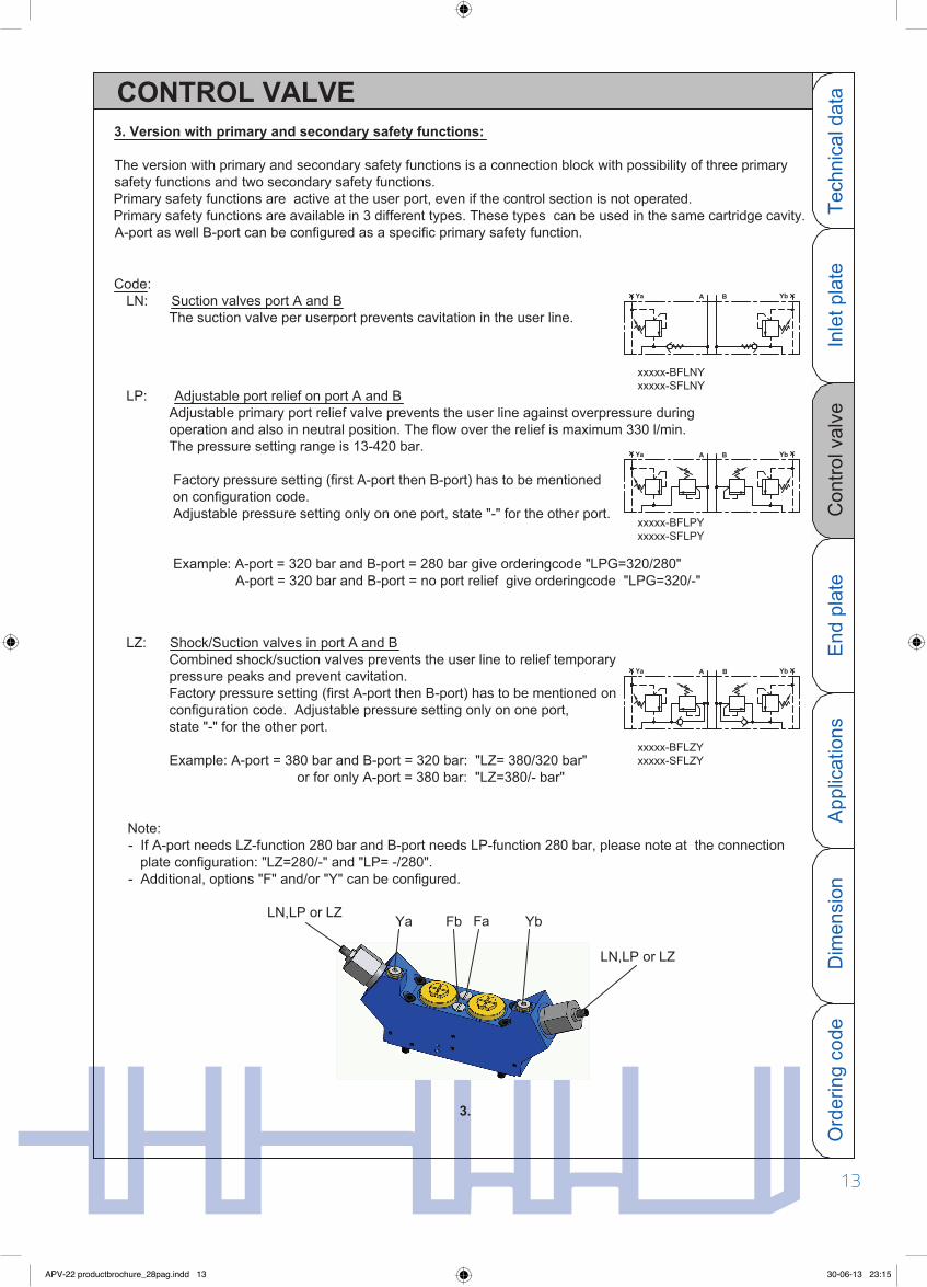
LP: Adjustable port relief on port A and B Adjustable primary port relief valve prevents the user line against overpressure during operation and also in neutral position. The flow over the relief is maximum 330 l/min. The pressure setting range is 13-420 bar.
Factory pressure setting (first A-port then B-port) has to be mentioned on configuration code. Adjustable pressure setting only on one port, state "-" for the other port.
Example: A-port = 320 bar and B-port = 280 bar give orderingcode "LPG=320/280" A-port = 320 bar and B-port = no port relief give orderingcode "LPG=320/-"
Code: LN: Suction valves port A and B The suction valve per userport prevents cavitation in the user line.
3. Version with primary and secondary safety functions:
The version with primary and secondary safety functions is a connection block with possibility of three primary safety functions and two secondary safety functions.
Primary safety functions are active at the user port, even if the control section is not operated.Primary safety functions are available in 3 different types. These types can be used in the same cartridge cavity.A-port as well B-port can be configured as a specific primary safety function.
LZ: Shock/Suction valves in port A and B Combined shock/suction valves prevents the user line to relief temporary pressure peaks and prevent cavitation. Factory pressure setting (first A-port then B-port) has to be mentioned on configuration code. Adjustable pressure setting only on one port, state "-" for the other port.
Example: A-port = 380 bar and B-port = 320 bar: "LZ= 380/320 bar" or for only A-port = 380 bar: "LZ=380/- bar"
Note:- If A-port needs LZ-function 280 bar and B-port needs LP-function 280 bar, please note at the connection plate configuration: "LZ=280/-" and "LP= -/280".- Additional, options "F" and/or "Y" can be configured.
App
licat
ions
O
rder
ing
code
Dim
ensi
onTe
chni
cal d
ata
Con
trol v
alve
End
pla
teIn
let p
late
Ya A B
BAYa
Yb
Yb
BAYa Yb
3.
Fa YbYaLN,LP or LZ
LN,LP or LZ
Fb
APV-22 productbrochure_28pag.indd 13 30-06-13 23:15

14
CONTROL SECTION
13
CONTROL VALVE
The unique modularity of the APV enables systems solutions for manufacturers of mobile machines, as a wide range of functions can be integrated/changed by the customer in an easy, flexible and cost-effective way.
Some examples are shown below.
OJEOJ
E
Spring and endcap with double control method electrical and hydraulic proportional.
4. Customized version:
Connection block with 4 LS-reliefs, 2 remote controlconnection and 2 2/2-way normally closed electrical cartridges.
Connection block for combining the amount of 2 sectionalflow's to 1 common SAE-port.Suction valves or shock/suction valves on A/B possible.
Connection block with LS-reliefs and 1 check valve.
APV-22 productbrochure_28pag.indd 14 30-06-13 23:15

1514
CONTROL VALVE
App
licat
ions
O
rder
ing
code
Dim
ensi
onTe
chni
cal d
ata
Con
trol v
alve
End
pla
teIn
let p
late
APV-22 valve block added to special size 32 manifold.
Double endcap for common piloting of 2 sections together.
Double springcap for common piloting of 2 sections together.
Combination APV-16 and APV-22.
APV-22 productbrochure_28pag.indd 15 30-06-13 23:15

16
Code PJ: For control method E or O
End plate with built-in pressure reducing valve for internal pilot pressure supply of 28 bar to the electrical pilot valves of each electrical proportional control valve or for external pilot pressure supply of 28 bar to the hydraulic joysticks.
Code PH: For control method H or O
End plate for manual or hydraulic operated valves.
15
END PLATE
22PH/P 22PJ
Note: The L-connection has to be connected as seperate drain to tank.APV..PJ
APV..PH
P2
T2
L
AO
LT2
P2
Code P: With additional P-port
Additional P-port to connect an extra P-line in systems with high pump flow.
APV..PJ..P
T2L
P2
AO
APV-22 productbrochure_28pag.indd 16 30-06-13 23:15

1716
END PLATE
Dim
ensi
onO
rder
ing
code
Tech
nica
l dat
aA
pplic
atio
ns
Con
trol v
alve
Inle
t pla
teE
nd p
late
Code Z: With Z-port
Z-port to connect the LS-signal of a second valve to the LS-cascade of the first valve , to be able to use the compensator of the first valve.
Code T: With additional T-port
Additional T-port.
M
Ø
22FOJC200/220/BF
a
P1
22S420B 22FOJC300/250/BF
ab
T1
LS
P
A
T
BA
P
b
22PJ2B
B
T
ABA B
APV..PJ..Z
APV..PJ..T
T2L
P2
LT2
AO
P2
Z
P2
Z
L
AO
T2
Note: In systems with a pumpflow > 380l/min use endplate with P2 port (Ordering code 22P...P). For reduction of the return pressure the use of the second tank connection T2 on the end plate is possible (ordering code 22P...T).
A0
APV-22 productbrochure_28pag.indd 17 30-06-13 23:15

18
22FEAMC300/300/B22U420B 22FEAMC300/300/B
a
BA
P
A B
T
22FEAMC300/300/BF
ab
BA
T
BA
P ab
A B
B
TP
A
22PJ3B
b
Example inlet plate code U.
Inlet plate for fixed displacement pump: 22U420BIf none of the control sections are in operation, the integrated 3-way compensator of the inlet plate 22U recirculates the flow to tank.Actuating one of the control sections, the specific load pressure is added as signal to the spring chamber. Actuating more control sections at the same time, the highest load pressure will be added (see shuttle valve cascade system).The maximum load signal pressure is controlled by the max. load pressure relief.If one or more of the users have to be set on a lower max. pressure, the control section can be configured with pressure reliefs per port (see for example the second section).
Code U:
Z
A
P
A
B
T
A
P
BA Ya
B
T
YbB
T2
P2
B
T
A
P
T2
Parallel circuit with fixed displacement pump: 22U and 22NWhen two valve blocks should be mounted on different places in a system one valve block can be configured with a 22N inlet plate. The valve block with the 22U is regulating the pump flow and the end plate 22P-Z has to be connected to the LS port of the second valve block with a 22N inlet plate. The max. load pressure relief of the 22N inlet plate has to be adjusted equally or lower as the max. load pressure relief at the main inlet plate 22U.
BA
APPLICATIONS Examples
17
M
P1
T1
T1
M
P1 P1
LS
T1
22FHC/B22U420B 22FHC/BFY 22PH2-Z 22N420B 22FHC/B 22PH-P
L L
P2
T2
L
P2
A0
APV-22 productbrochure_28pag.indd 18 30-06-13 23:15

19
22FHBA330/330/B22N420B 22FHFC150/200/B
A B
TP
BA
22FHFC250/250/B
P T
BA
A B
A
P
A
Example inlet plate code N.
22PH3B
B
T
T2
B
Inlet plate for LS-pumps: 22N240BThe version 22N is the inlet plate for the P, T and LS connection.The adjustable max. pressure relief for the load signal is standard integrated.
Code N:
BA
TP T
BA
P
A B A B
B
TP
A B
TP
A
A B BA
A
P T
B
A B
Series circuit with fixed displacement pump: 22U and 22RFor the same condition as the parallel circuit a series circuit can be used. The advantage of a series circuit is that there is not a longer LS signal line that shall give a lower signal under colder conditions.In the 22R inlet plate the tank circuit is disconnected from the control sections and there is an additional possibility of directing the pump flow from P to R in order to feed another circuit. Please note that with this type of valve block the T2 connection in the end plate has to be connected with tank.
bababa
baba
P1
M
T1
M
P
R
LS
P1
T1
22FOJC/BF22U420B 22FOJC/BF 22FOJC/BF 22PH3BJ
22R420B 22FOJMA/B 22FOJMA/BF 22PH2BJ
MØ
APPLICATIONS Examples
End
pla
teO
rder
ing
code
App
licat
ions
D
imen
sion
Con
trol v
alve
Inle
t pla
teTe
chni
cal d
ata
P2
L
LT2
P2
AO
P2
AO
LT2
APV-22 productbrochure_28pag.indd 19 30-06-13 23:15

20
22FOJC280/220/BF22FOJC330/330/BF22S420B
T
BA
P
BA
22PJ2B
P
A B
T
A B
Inlet plate for LS-pump: 22S420BThe version 22S has primary overpressure safety function.The relief valve can be adjusted to max. pumpline pressure and the relief spool reduces the overpressure by relieving the pump flow to tank.
Code S:
a b a b
MØ
22N420B
22N420B
a bT
BA
P
BA
T
B
a
A
P b
A B
T
B
a
A
P
BA
BA
TP
A B
b a b Pa
A
A
T b
B
B
P1
LS
T1
P1
LS
T1
P1
LS
T1
ØM
T2
L
P2
P2
LT2
P2
T2L
APPLICATIONS Examples
19
Example inlet plate code S.
A0
A0
A0
APV-22 productbrochure_28pag.indd 20 30-06-13 23:15

21
APPLICATIONS Examples
End
pla
teO
rder
ing
code
App
licat
ions
D
imen
sion
Con
trol v
alve
Inle
t pla
teTe
chni
cal d
ata
P
LS
1
T1
A
P T
B
a b
T2
La
B
TP
A
ba
A
P T
B
ba
A
P T
B
b
AYa B YbYa A B YbA BYa A B Yb
A0
APV-22 productbrochure_28pag.indd 21 30-06-13 23:15

2221
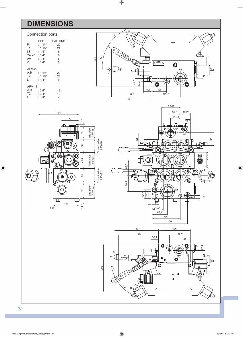
Connection ports
PT,T2A,BLSLYa,YbA0Z
BSP SAE ORB: 1 1/4" 20: 1 1/2" 24: 1 1/4" 20: 1/4" 6: 1/4" 6: 1/4" 6: 1/4" 6: 1/4" 6
DIMENSIONSb
a
34°
34°
191
231
81,5
35,5
172
62
8712
0,5
180
22,2
34,7
21823
161
Directional control valve
616168,5
Inlet plate
35,8
178,
5
155,
511
1
111
14,567
End plate
P2
Z
AB
AB
A
P1
T1
B
A0
LT2FaFbFb Fa
YbYa
YaYb
61 66,559
66,532,5
68
49,4
644
14
150
65,4
14
38,5
31
A0
13,7
15
MP
LS
APV-22 productbrochure_28pag.indd 22 30-06-13 23:15

23
Mounting holes M14 x 17
DIMENSIONS
End
pla
teO
rder
ing
code
App
licat
ions
C
ontro
l val
veIn
let p
late
Tech
nica
l dat
aD
imen
sion
Weight assembly kit: with 1 control valvewith 2 control valvewith 3 control valvewith 4 control valvewith 5 control valvewith 6 control valvewith 7 control valvewith 8 control valvewith 9 control valvewith 10 control valve
N 2,91 3,574,234,895,556,216,877,538,198,85
Weight: Connection blockBBFYBFLZY
End plate22PH22PJ
N
84 85 7,512
8789888588
Weight: Inlet plate22N22U/S/ROpt. D/EOpt. A/L
Spool section22FE* 22FE*M 22FH22FOJ22FOJM
N
303265
8383
Directional control valve
6114,5
End plate
67
Inlet plate
61 61 68,5 35,8
53,5
1585
,5
145
14
15
3015
2
30
APV-22 productbrochure_28pag.indd 23 30-06-13 23:15
24
5653
74,5
6167
14,5
9,5
End
pla
teA
PV
-16
End
pla
teA
PV
-22
Inle
t pla
teco
mbi
Con
trol v
alve
AP
V-1
6C
ontro
l val
veA
PV
-22
77
111
231
174
T1 P1
T2
T2
L
40,25
24,5
L
A0
44,75
55,5
83,25
54 5514 49,4
3138,5
65,4
120
66,5
69,5
136
27,416
89,75
49
P2
Z
Ya
YbYa
Yb
AB
AB
Fa
Fb
Fa
Fb
62120,5
22,234
,7
P2
Z
b
a
34°
34°
191
231
35,5
172
35,1
a
b34°
34°
189
170
203
Connection ports
P1T1LSYa,YbA0Z
APV-22A,BT2L
APV-16A,BT2L
BSP SAE ORB: 1 1/4" 20: 1 1/2" 24: 1/4" 6: 1/4" 6: 1/4" 6: 1/4" 6
: 1 1/4" 20: 1 1/2" 24: 1/4" 6
: 3/4" 12: 3/4" 12: 1/8" 4
A0
150
A0
14
23
DIMENSIONS
APV-22 productbrochure_28pag.indd 24 30-06-13 23:15

25
61 6774,556539,5 14,5
End plateAPV-22
End plateAPV-16
Inlet platecombi
Control valveAPV-22
Control valveAPV-16
108,
5
27,5
31,7
35
166
15
Mounting holes APV-22: M14 x 17
DIMENSIONS
End
pla
teO
rder
ing
code
App
licat
ions
C
ontro
l val
veIn
let p
late
Tech
nica
l dat
aD
imen
sion
Mounting holes APV-16: M8 x 12
APV-22 productbrochure_28pag.indd 25 30-06-13 23:15

2625
CONFIGURATION CODE
8 With 8 control valveWith 9 control valveWith 10 control valve
Variants:
With additional T-port
Port connections:Thread in BSP
With additional P-port
B
TP
910
D3 " 24VDC and N.O.
Plate version
END PLATE
Assembly kits:With 1 control valveWith 2 control valveWith 3 control valveWith 4 control valveWith 5 control valveWith 6 control valveWith 7 control valve
For control method: H or O
Viton seals
Electrical proportional pressure relief: 12VDC " 24VDC and N.C.
" 24VDCLS amplifier only in combination with N or S-plate
22 22
234
67
5
1
PH
Size
E1E2
D4
L
/ B222 PJ P
Plate versionFor LS-pump
For fixed displacement pump
INLET PLATE
Variants:
Port connections:Thread in BSP
Anti-saturation function
Pressure adjusment in bar:
For LS-pump and max. pressure valve in P
For fixed displacement pump and serial connection
Max. 420 bar (factory setting 350 bar)
Pump unloading function: 12VDC and N.O. " 12VDC and N.C.
N
A
B
D2D1
UR
S
420
Size22 22
B420N22 AD1
Combiplate/C
PJ For control method: E or O + port A0 for joystick supply: 28bar
Z With Z-port
/I
Thread in SAE ORBS
Viton seals/I
Thread in SAE ORBS
APV-22 productbrochure_28pag.indd 26 30-06-13 23:15

27
CONFIGURATION CODE
End
pla
teA
pplic
atio
ns
Dim
ensi
onC
ontro
l val
veIn
let p
late
Tech
nica
l dat
aO
rder
ing
code
Y Remote pressure connection on port A and B
*** = give pressure setting A and B-port** = one type per port, for LP and LZ give pressure setting
22FEBMC330/300/BFY (F=380/320bar)22F1EBMC200/250/BLPY (LP=280/200)22PJ2BP
22N320BAD1Example:
FY (F=380/320bar)
EBM " " : 24VDC and additional manual control
Manual proportional: spring return
PART: CONNECTION BLOCK
Shock/Suction valves port A and B
Suction valves port A and BAdjustable port relief valve on port A and B
Adjustable pressure setting on port A and B ***
Choose the flow: port A / port B (max. 330 l/min)
" " and additional manual control
" " : with detent (3 positions) " " : with friction brake and centre detent
Variants:
/I
FLN**LP**LZ**
Viton seals
B Thread in BSPPort connections:
A
.../...Max. flow: (l/min)A,B,C,D,F,G,K,OMain spool type:
HFHB
OJOJM
HR
Hydraulic proportional
PART: SPOOL SECTION
" " : 24VDC
Electrical proportional: 12VDC
With damped compensator
" " : 12VDC and additional manual control
With check valve function
With damped compensator incl. check valve function
With compensator incl. check valve function
2222
N No compensator
EBEAMEA
N1Control method:
F
F2F3*
F1*With compensatorCompensator:
SizeF22 330/300CEBM / B
CONTROL VALVE
" " : 24VDC with pinEFEH " " : 24VDC with II 2G Ex mb II T4
EE " " : 12VDC with pin
S Thread in SAE ORB
* = for option F1 and F3 the max. flow is 260l/min
APV-22 productbrochure_28pag.indd 27 30-06-13 23:15

AMCA Hydraulic Fluid Power BVB. Kuiperweg 339792 PJ Ten PostThe Netherlands
P.O. Box 189790 AA Ten BoerThe Netherlands
Tel.: +31 (0)50-3023577Fax: +31(0)[email protected]
APV-22 productbrochure_28pag.indd 28 30-06-13 23:15

![Savi EHS Adapters APV-60 & APV-65 Getting Started · 3 4 APV-60 System Connections APV-60 System Connections Setup 1 - [HIS Wired] Supported Phones Avaya 1608, 1616, 9620, 9630, 9640,](https://img.pdfslide.us/doc/110x75/5e08a259eb02f47481101e4f/savi-ehs-adapters-apv-60-apv-65-getting-started-3-4-apv-60-system-connections.jpg)