Embed Size (px)
Citation preview
R
www.MaterialsViews.comwww.advmat.de
EVIE
W
Applications of Ultrasound to the Synthesis ofNanostructured Materials
By Jin Ho Bang and Kenneth S. Suslick*
Recent advances in nanostructured materials have been led by the develop-
ment of new synthetic methods that provide control over size, morphology, and
nano/microstructure. The utilization of high intensity ultrasound offers a facile,
versatile synthetic tool for nanostructured materials that are often unavailable
by conventional methods. The primary physical phenomena associated with
ultrasound that are relevant to materials synthesis are cavitation and
nebulization. Acoustic cavitation (the formation, growth, and implosive
collapse of bubbles in a liquid) creates extreme conditions inside the collapsing
bubble and serves as the origin of most sonochemical phenomena in liquids or
liquid-solid slurries. Nebulization (the creation of mist from ultrasound passing
through a liquid and impinging on a liquid-gas interface) is the basis for
ultrasonic spray pyrolysis (USP) with subsequent reactions occurring in the
heated droplets of the mist. In both cases, we have examples of phase-
separated attoliter microreactors: for sonochemistry, it is a hot gas inside
bubbles isolated from one another in a liquid, while for USP it is hot droplets
isolated from one another in a gas. Cavitation-induced sonochemistry provides
a unique interaction between energy and matter, with hot spots inside the
bubbles of �5000K, pressures of �1000bar, heating and cooling rates of
>1010 K s�1; these extraordinary conditions permit access to a range of
chemical reaction space normally not accessible, which allows for the synthesis
of a wide variety of unusual nanostructured materials. Complementary to
cavitational chemistry, the microdroplet reactors created by USP facilitate the
formation of a wide range of nanocomposites. In this review, we summarize the
fundamental principles of both synthetic methods and recent development in
the applications of ultrasound in nanostructured materials synthesis.
1. Introduction
Nanoscience and nanotechnology have grown at an enormous ratefor the last three decades, and recent advances in nanostructuredmaterials have opened up new opportunities for diverse applica-tions in electronics, catalysis, energy, materials chemistry and evenbiology. Materials in the nanometer-size regime often exhibitproperties distinct from their bulk counterparts, in part because
[*] Prof. K. S. Suslick, Dr. J. H. BangSchool of Chemical SciencesUniversity of Illinois at Urbana-Champaign600 South Mathews Avenue, Urbana, Illinois 61801 (USA)E-mail: [email protected]
DOI: 10.1002/adma.200904093
Adv. Mater. 2010, 22, 1039–1059 � 2010 WILEY-VCH Verlag GmbH & Co. KGaA, Weinhei
clusters that small have electronic structuresthat have a high density of states, but not yetcontinuous bands. Nanostructured materialshave been prepared by a variety of syntheticmethods, including gas phase techniques(e.g., molten metal evaporation, flashvacuum thermal and laser pyrolysis decom-position of volatile organometallics), liquidphase methods (e.g., reduction of metalhalides with various strong reductants,colloidal techniques with controlled nuclea-tion), and mixed phase approaches (e.g.,synthesis of conventional heterogeneouscatalysts on oxide supports, metal atom vapordeposition into cryogenic liquids, explosiveshock synthesis). One could claim thatselecting an appropriate synthetic routeultimately determines the success or failureof nanostructured materials synthesis,because physical properties and applicationsof nanostructured materials are heavilydependent upon how they are prepared.The importance of choosing a propersynthetic route in designing nanostructuredmaterials has been a driving force for thedevelopment of new methodologies forseveral decades. Indeed, this has led scien-tists’ interest to the development of versatileand generalized synthetic methods readilyadaptable for the preparation of a variety ofnanostructuredmaterials. Among a variety ofapproaches, the utilization of ultrasound formaterials synthesis has been extensively
examined over many years, and is now positioned as one of themost powerful tools in nanostructured materials synthesis. In thisreview, the two most successful ultrasound-assisted syntheticmethods (sonochemistry and ultrasonic spray pyrolysis) will bediscussed to provide a fundamental understanding of their basicprinciples and to demonstrate the powerful and unique aspects ofultrasound in nanostructured materials synthesis.
2. Sonochemistry
2.1. Acoustic Cavitation
Chemistry deals with the interaction between energy and matter,and chemical reactions require some form of energy (e.g., heat,
m 1039
REVIE
W
www.advmat.dewww.MaterialsViews.com
Jin Ho Bang received his B.S. andM.S. degrees from SeoulNational University in 1999 and2001, respectively. During hisgraduate studies in South Korea,he majored in electrochemistryunder the supervision ofProfessor Hasuck Kim. Afterearning a M.S. degree, he movedto the University of Illinois atUrbana-Champaign in 2003 andreceived his Ph.D. degree in 2008.
Under the guidance of Professor Kenneth S. Suslick, he hadworked on the synthesis of nanostructured materials and theirapplications, including hydrogen evolution photocatalysts, fuelcells, and cellular imaging. Currently, he is working onquantum dot solar cells with Professor Prashant V. Kamat atthe University of Notre Dame as a postdoctoral researchassociate.
Kenneth S. Suslick received hisB.S. from the California Instituteof Technology in 1974, his Ph.D.from Stanford University in 1978,and came to the University ofIllinois at Urbana-Champaignimmediately thereafter. Currently,he is the Marvin T. SchmidtProfessor of Chemistry and also aProfessor of Materials Scienceand Engineering and of theBeckman Institute for Advanced
Science and Technology. He is a fellow of the MRS, AAAS, andthe Acoustical Society of America (ASA). His two majorresearch areas are the chemical and physical effects ofultrasound (which includes nanomaterials synthesis andsonoluminescence) and the bioinorganic and materialschemistry of metalloporphyrins, and now especially theirapplications for chemical sensing and artificial olfaction.
Figure 1. Islands of chemistry as a function of time, pressure, and energy.Adapted from [2] with permission. Copyright 1990, American Associationfor the Advancement of Science.
1040
light, radiation, electric potential, etc.) to proceed.[1,2] Precisecontrol over chemical reactions is a key to the success ofnanostructured materials synthesis, but currently such control islimited to the manipulations of various reaction parametersincluding time, energy input, and pressure. These parameters,however, are adjustable only within a certain boundaries definedby the energy source employed in reactions. Each type of energyhas its own realm of reaction conditions determined by itsinherent reaction parameters, as depicted in Figure 1.[3]
Compared to traditional energy sources, ultrasonic irradiationprovides rather unusual reaction conditions (a short duration ofextremely high temperatures and pressures in liquids) thatcannot be realized by other methods.
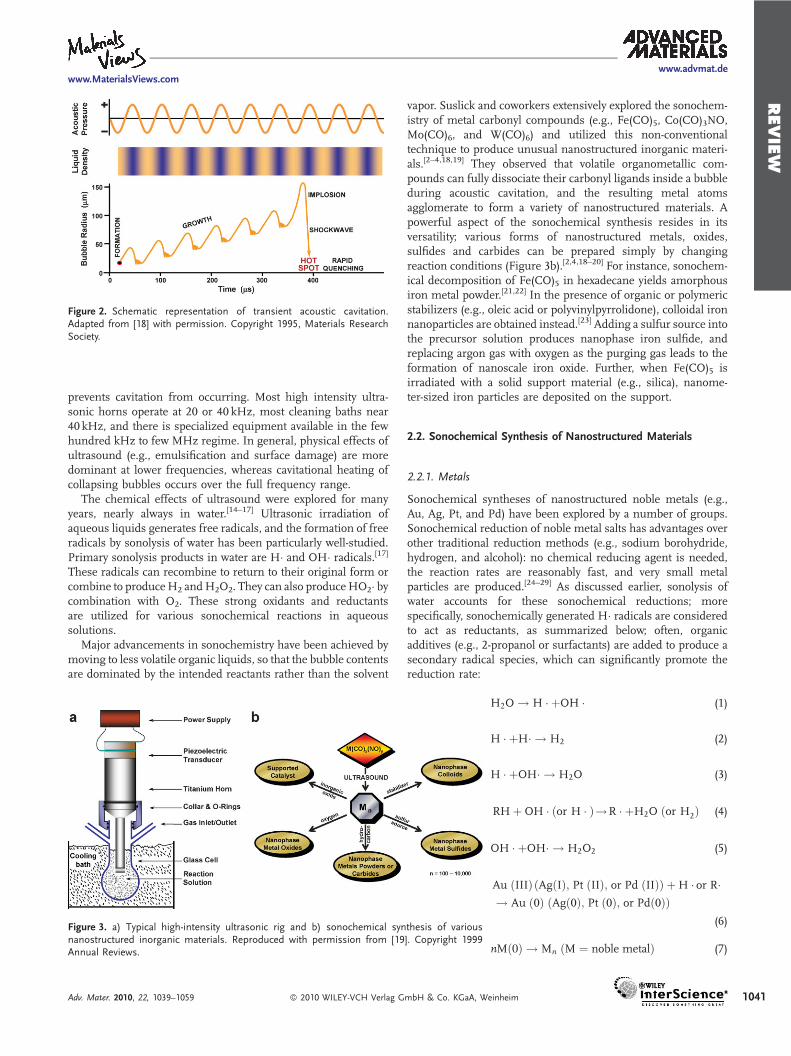
Interestingly, such extraordinary conditions are not deriveddirectly from ultrasound itself: acoustic wavelengths are muchlarger than molecular dimensions. Thus, no direct, molecular-level interaction between ultrasound and the chemical speciestakes place. Instead, acoustic cavitation (i.e., the formation,growth, and implosive collapse of bubbles in liquids), driven byhigh intensity ultrasound accounts for the chemical effects ofultrasound.[4] When liquids are irradiated with ultrasound, thealternating expansive and compressive acoustic waves createsbubbles (i.e., cavities) and makes the bubbles oscillate (Figure 2).The oscillating bubbles can accumulate ultrasonic energyeffectively while growing to a certain size (typically tens ofmm). Under the right conditions, a bubble can overgrow andsubsequently collapse, releasing the concentrated energy storedin the bubble within a very short time (with a heating and coolingrate of >1010 K s�1). This cavitational implosion is very localizedand transient with a temperature of �5000K and a pressure of�1000 bar.[2]
These extreme conditions created during acoustic cavitationcan give rise to light emission. This intriguing physicalphenomenon, known as sonoluminescence, was first observedduring the ultrasonic irradiation of water in 1934 by Frenzeland Schultes,[5] and afterward, has been systematicallyinvestigated by several research groups. Because of the transient
� 2010 WILEY-VCH Verlag Gmb
nature of acoustic cavitation, sonoluminescence has beenexplored as a spectroscopic probe to investigate reactionconditions (e.g., temperature and pressure) during ultrasonicirradiation.[6–13]
A variety of sonochemical apparatuses are commerciallyavailable with several designs: ultrasonic cleaning baths,direct-immersion ultrasonic horns, and flow reactors arecommon examples. Cleaning baths have insufficient intensityfor most applications, but are useful for liquid-solid reactionswith easily passivated but reactive solids (e.g., Li, Mg). A typicallaboratory-scale sonochemical apparatus (Figure 3a) consists of ahigh-intensity ultrasonic titanium horn driven by a piezoelectrictransducer which is directly introduced into a thermostated glassreactor having gas inlets and outlets.[2] Cavitation occurs over avery wide range of frequencies, from tens of Hz to tens of MHz;above that frequency regime, the intrinsic viscosity of liquids
H & Co. KGaA, Weinheim Adv. Mater. 2010, 22, 1039–1059
REVIE
W
www.MaterialsViews.comwww.advmat.de
Figure 2. Schematic representation of transient acoustic cavitation.Adapted from [18] with permission. Copyright 1995, Materials ResearchSociety.
prevents cavitation from occurring. Most high intensity ultra-sonic horns operate at 20 or 40 kHz, most cleaning baths near40 kHz, and there is specialized equipment available in the fewhundred kHz to few MHz regime. In general, physical effects ofultrasound (e.g., emulsification and surface damage) are moredominant at lower frequencies, whereas cavitational heating ofcollapsing bubbles occurs over the full frequency range.
The chemical effects of ultrasound were explored for manyyears, nearly always in water.[14–17] Ultrasonic irradiation ofaqueous liquids generates free radicals, and the formation of freeradicals by sonolysis of water has been particularly well-studied.Primary sonolysis products in water are H� and OH� radicals.[17]These radicals can recombine to return to their original form orcombine to produceH2 andH2O2. They can also produceHO2� bycombination with O2. These strong oxidants and reductantsare utilized for various sonochemical reactions in aqueoussolutions.
Major advancements in sonochemistry have been achieved bymoving to less volatile organic liquids, so that the bubble contentsare dominated by the intended reactants rather than the solvent
Figure 3. a) Typical high-intensity ultrasonic rig and b) sonochemical synnanostructured inorganic materials. Reproduced with permission from [19Annual Reviews.
Adv. Mater. 2010, 22, 1039–1059 � 2010 WILEY-VCH Verlag G
vapor. Suslick and coworkers extensively explored the sonochem-istry of metal carbonyl compounds (e.g., Fe(CO)5, Co(CO)3NO,Mo(CO)6, and W(CO)6) and utilized this non-conventionaltechnique to produce unusual nanostructured inorganic materi-als.[2–4,18,19] They observed that volatile organometallic com-pounds can fully dissociate their carbonyl ligands inside a bubbleduring acoustic cavitation, and the resulting metal atomsagglomerate to form a variety of nanostructured materials. Apowerful aspect of the sonochemical synthesis resides in itsversatility; various forms of nanostructured metals, oxides,sulfides and carbides can be prepared simply by changingreaction conditions (Figure 3b).[2,4,18–20] For instance, sonochem-ical decomposition of Fe(CO)5 in hexadecane yields amorphousiron metal powder.[21,22] In the presence of organic or polymericstabilizers (e.g., oleic acid or polyvinylpyrrolidone), colloidal ironnanoparticles are obtained instead.[23] Adding a sulfur source intothe precursor solution produces nanophase iron sulfide, andreplacing argon gas with oxygen as the purging gas leads to theformation of nanoscale iron oxide. Further, when Fe(CO)5 isirradiated with a solid support material (e.g., silica), nanome-ter-sized iron particles are deposited on the support.
2.2. Sonochemical Synthesis of Nanostructured Materials
2.2.1. Metals
Sonochemical syntheses of nanostructured noble metals (e.g.,Au, Ag, Pt, and Pd) have been explored by a number of groups.Sonochemical reduction of noble metal salts has advantages overother traditional reduction methods (e.g., sodium borohydride,hydrogen, and alcohol): no chemical reducing agent is needed,the reaction rates are reasonably fast, and very small metalparticles are produced.[24–29] As discussed earlier, sonolysis ofwater accounts for these sonochemical reductions; morespecifically, sonochemically generated H� radicals are consideredto act as reductants, as summarized below; often, organicadditives (e.g., 2-propanol or surfactants) are added to produce asecondary radical species, which can significantly promote thereduction rate:
thesis of various]. Copyright 1999
mbH & Co. KGaA, W
H2O ! H � þOH � (1)
H � þH� ! H2 (2)
H � þOH� ! H2O (3)
RHþ OH � ðor H � Þ!R � þH2O ðor H2Þ (4)
OH � þOH� ! H2O2 (5)
Au ðIIIÞðAgðIÞ; Pt ðIIÞ; or Pd ðIIÞÞ þH � or R�! Au ð0Þ ðAgð0Þ; Pt ð0Þ; or Pdð0ÞÞ
(6)
nMð0Þ ! Mn ðM ¼ noble metalÞ (7)
einheim 1041
REVIE
W
www.advmat.dewww.MaterialsViews.com
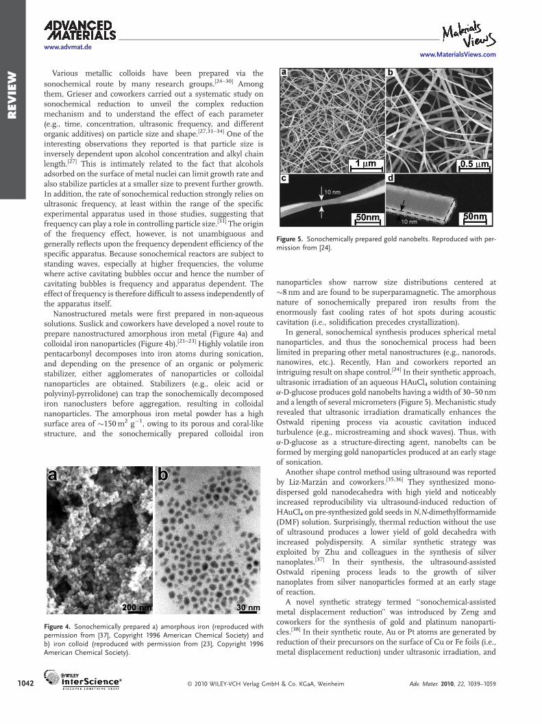
Figure 5. Sonochemically prepared gold nanobelts. Reproduced with per-mission from [24].
1042
Various metallic colloids have been prepared via the
sonochemical route by many research groups.[24–30] Amongthem, Grieser and coworkers carried out a systematic study onsonochemical reduction to unveil the complex reductionmechanism and to understand the effect of each parameter(e.g., time, concentration, ultrasonic frequency, and differentorganic additives) on particle size and shape.[27,31–34] One of theinteresting observations they reported is that particle size isinversely dependent upon alcohol concentration and alkyl chainlength.[27] This is intimately related to the fact that alcoholsadsorbed on the surface of metal nuclei can limit growth rate andalso stabilize particles at a smaller size to prevent further growth.In addition, the rate of sonochemical reduction strongly relies onultrasonic frequency, at least within the range of the specificexperimental apparatus used in those studies, suggesting thatfrequency can play a role in controlling particle size.[31] The originof the frequency effect, however, is not unambiguous andgenerally reflects upon the frequency dependent efficiency of thespecific apparatus. Because sonochemical reactors are subject tostanding waves, especially at higher frequencies, the volumewhere active cavitating bubbles occur and hence the number ofcavitating bubbles is frequency and apparatus dependent. Theeffect of frequency is therefore difficult to assess independently ofthe apparatus itself.
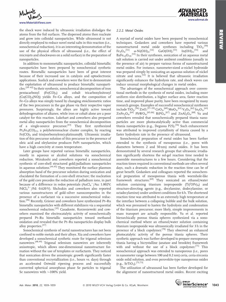
Nanostructured metals were first prepared in non-aqueoussolutions. Suslick and coworkers have developed a novel route toprepare nanostructured amorphous iron metal (Figure 4a) andcolloidal iron nanoparticles (Figure 4b).[21–23] Highly volatile ironpentacarbonyl decomposes into iron atoms during sonication,and depending on the presence of an organic or polymericstabilizer, either agglomerates of nanoparticles or colloidalnanoparticles are obtained. Stabilizers (e.g., oleic acid orpolyvinyl-pyrrolidone) can trap the sonochemically decomposediron nanoclusters before aggregation, resulting in colloidalnanoparticles. The amorphous iron metal powder has a highsurface area of �150m2 g�1, owing to its porous and coral-likestructure, and the sonochemically prepared colloidal iron
Figure 4. Sonochemically prepared a) amorphous iron (reproduced withpermission from [37], Copyright 1996 American Chemical Society) andb) iron colloid (reproduced with permission from [23], Copyright 1996American Chemical Society).
� 2010 WILEY-VCH Verlag Gmb
nanoparticles show narrow size distributions centered at�8 nm and are found to be superparamagnetic. The amorphousnature of sonochemically prepared iron results from theenormously fast cooling rates of hot spots during acousticcavitation (i.e., solidification precedes crystallization).
In general, sonochemical synthesis produces spherical metalnanoparticles, and thus the sonochemical process had beenlimited in preparing other metal nanostructures (e.g., nanorods,nanowires, etc.). Recently, Han and coworkers reported anintriguing result on shape control.[24] In their synthetic approach,ultrasonic irradiation of an aqueous HAuCl4 solution containinga-D-glucose produces gold nanobelts having a width of 30–50 nmand a length of several micrometers (Figure 5). Mechanistic studyrevealed that ultrasonic irradiation dramatically enhances theOstwald ripening process via acoustic cavitation inducedturbulence (e.g., microstreaming and shock waves). Thus, witha-D-glucose as a structure-directing agent, nanobelts can beformed by merging gold nanoparticles produced at an early stageof sonication.
Another shape control method using ultrasound was reportedby Liz-Marzan and coworkers.[35,36] They synthesized mono-dispersed gold nanodecahedra with high yield and noticeablyincreased reproducibility via ultrasound-induced reduction ofHAuCl4 on pre-synthesized gold seeds inN,N-dimethylformamide(DMF) solution. Surprisingly, thermal reduction without the useof ultrasound produces a lower yield of gold decahedra withincreased polydispersity. A similar synthetic strategy wasexploited by Zhu and colleagues in the synthesis of silvernanoplates.[37] In their synthesis, the ultrasound-assistedOstwald ripening process leads to the growth of silvernanoplates from silver nanoparticles formed at an early stageof reaction.
A novel synthetic strategy termed ‘‘sonochemical-assistedmetal displacement reduction’’ was introduced by Zeng andcoworkers for the synthesis of gold and platinum nanoparti-cles.[38] In their synthetic route, Au or Pt atoms are generated byreduction of their precursors on the surface of Cu or Fe foils (i.e.,metal displacement reduction) under ultrasonic irradiation, and
H & Co. KGaA, Weinheim Adv. Mater. 2010, 22, 1039–1059
REVIE
W
www.MaterialsViews.comwww.advmat.de
the shock wave induced by ultrasonic irradiation dislodges theatoms from the foil surfaces. The dispersed atoms then nucleateand grow into colloidal nanoparticles. While ultrasound is notdirectly employed to reduce novel metal salts in this reaction (i.e.,sonochemical reduction), it is an interesting demonstration of theuse of the physical effects of ultrasound (i.e., the effect ofmicrojets and shockwaves on a solid surface) in the preparation ofnanoparticles.
In addition to monometallic nanoparticles, colloidal bimetallicnanoparticles have been prepared by sonochemical syntheticroutes. Bimetallic nanoparticles have been of great interestbecause of their increased use in catalysis and optoelectronicapplications. Suslick and coworkers were the first to demonstratethe exploitation of ultrasound to produce bimetallic nanoparti-cles.[39–42] In their synthesis, sonochemical decomposition of ironpentacarbonyl (Fe(CO)5) and cobalt tricarbonylnitrosyl(Co(CO)3(NO)) yields Fe–Co alloys, and the composition ofFe–Co alloys was simply tuned by changing stoichiometric ratiosof the two precursors in the gas phase via their respective vaporpressures. Surprisingly, the alloys are highly active towarddehydrogenation of alkanes, while iron or cobalt alone are a poorcatalyst for this reaction. Lukehart and coworkers also preparedmetal alloy nanoparticles from the sonochemical decompositionof a single-source precursor.[43] They first synthesizedPt3Fe3(CO)15, a polyheteronuclear cluster complex, by reactingFe(CO)5 and tris(norbornylene)-platinum(0). Ultrasonic irradia-tion of this precursor solution of this precursor in the presence ofoleic acid and oleylamine produces FePt nanoparticles, whichhave a high coercivity at room temperature.
Later groups have reported various bimetallic nanoparticles,mostly in aqueous or alcohol solutions via sonochemicalreduction. Mizukoshi and coworkers reported a sonochemicalsynthesis of core-shell structured gold/palladium nanoparticlesin aqueous solutions.[44,45] They monitored the surface plasmonabsorption band of the precursor solution during sonication andelucidated the formation of a core-shell structure; the nucleationof the gold core precedes the reduction of palladium ions, in partbecause of a difference in redox potentials (AuCl4
�/Au: 1.002V;PdCl4
2�/Pd: 0.620V). Shchukin and coworkers also reportedvarious nanostructures of gold–silver nanocomposites in thepresence of a surfactant via a successive sonochemical reduc-tion.[46] Recently, Grieser and coworkers have synthesized Pt–Rubimetallic nanoparticles with different stabilizers via a sequentialsonochemical reduction.[32] Casadonte, Korzeniewski and cow-orkers examined the electrocatalytic activity of sonochemicallyprepared Pt–Ru bimetallic nanoparticles toward methanoloxidation and revealed that the Pt–Ru nanoparticles display bulkalloy properties.[47]
Sonochemical synthesis of metal nanostructures has not beenconfined to noble metals and their alloys. Xia and coworkers havedeveloped a sonochemical synthetic route for trigonal seleniumnanowires.[48,49] Trigonal selenium nanowires are inherentlyanisotropic, which allows one-dimensional nanostructure for-mation without the use of templates or surfactants. They noticedthat sonication drives the anisotropic growth significantly fasterthan conventional recrystallization (i.e., hours vs. days) throughan accelerated Ostwald ripening process and successfullyconverted spherical amorphous phase Se particles to trigonalSe nanowires with �100% yield.
Adv. Mater. 2010, 22, 1039–1059 � 2010 WILEY-VCH Verlag G
2.2.2. Metal Oxides
A myriad of metal oxides have been prepared by sonochemicaltechniques. Gedanken and coworkers have reported variousnanostructured metal oxide syntheses including TiO2,
[50]
Fe3O4,[51] a-Ni(OH)2,
[52] GaO(OH),[53] In(OH)3,[54] and
BaFe12O19.[55] In their syntheses, sonication of an aqueous metal
salt solution is carried out under ambient conditions (usually inthe presence of air) to prepare various forms of nanostructuredmetal oxides. For instance, nanometer-sized a-nickel hydroxidewas prepared simply by sonicating an aqueous solution of nickelnitrate and urea.[52] It is believed that ultrasonic irradiationsignificantly enhances the hydrolysis rate, and shock waves caninduce unusual morphological changes in metal oxides.
The advantages of the sonochemical approach over conven-tional methods in the synthesis of metal oxides, including moreuniform size distribution, a higher surface area, faster reactiontime, and improved phase purity, have been recognized by manyresearch groups. Examples of successful sonochemical synthesesinclude TiO2,
[56] ZnO,[57–59] CeO2,[60] MoO3,
[61] V2O5,[62] In2O3,
[63]
ZnFe2O4,[64] PbWO4,
[65,66] BiPO4,[67] and ZnAl2O4.
[68] Yu andcoworkers revealed that sonochemically prepared titania nano-particles are more photocatalytically active than commercialtitania nanoparticles (e.g., Degussa P25).[56] Such enhancementwas attributed to improved crystallinity of titania caused by afaster hydrolysis rate in the presence of ultrasound.
Sonochemical preparation of metal oxides has been furtherextended to the synthesis of mesoporous (i.e., pores withdiameters between 2 and 50 nm) metal oxides. It has beendemonstrated by several research groups that ultrasonic irradia-tion significantly shortens the sol-gel reaction time needed toassemble mesostructures to a few hours. Considering that thereaction times required in conventional methods are often severaldays, such a dramatic reduction in the reaction time can be ofgreat benefit. Gedanken and colleagues reported the sonochem-ical preparation of mesoporous titania with wormhole-likeframework structures.[69] They sonicated an ethanol/watersolution containing titanium isopropoxide (Ti(iOPr)4) andstructure-directing agents (e.g., decylamine, dodecylamine, oroctadecylamine) under ambient conditions for 6 h. The shortenedreaction time was attributed to an extremely high temperature atthe interface between a collapsing bubble and the bulk solution,which was presumed to hasten the hydrolysis and condensationof the titanium precursor; more likely, simple improvements inmass transport are actually responsible. Yu et al. reportedhierarchically porous titania spheres synthesized via a sono-chemical method where an ethanol/water solution containingtitanium isopropoxide was ultrasonically irradiated for 3 h in thepresence of a block copolymer.[70] They observed an enhancedphotocatalytic activity of the porous titania spheres. Theirsynthetic approach was further developed to prepare mesoporoustitania having a bicrystalline (anatase and brookite) frameworkwith and without the use of a block copolymer.[71] Thissonochemical approach was extended to nanoporous (i.e., poresin nanometer range between 100 and 0.2 nm) ceria, ceria-zirconiaoxide solid solution, and even perovskite-type nanoporous oxides(e.g., SrTiO3).
[72,73]
The utilization of ultrasound has been further developed forthe alignment of nanostructured metal oxides. Recent exciting
mbH & Co. KGaA, Weinheim 1043
REVIE
W
www.advmat.dewww.MaterialsViews.com
Figure 6. Tilt-view SEM images of vertically aligned ZnO rods producedusing sonochemical-induced anisotropic growth of ZnO along the (0001).Reproduced with permission from [74].
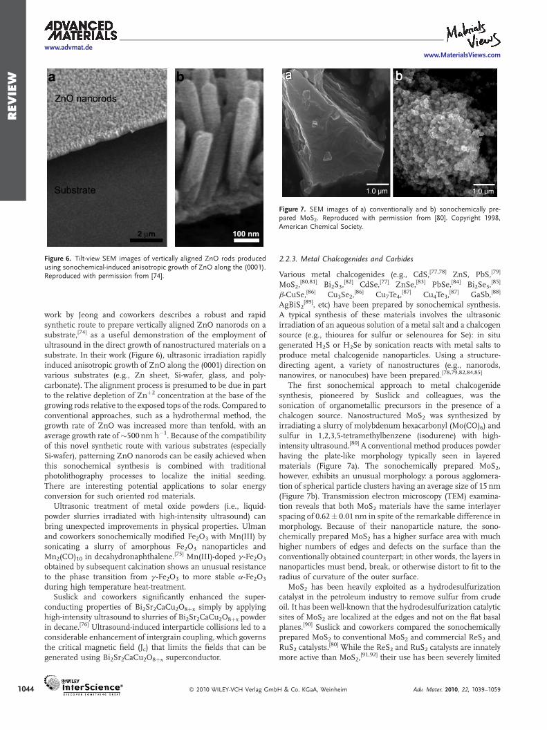
Figure 7. SEM images of a) conventionally and b) sonochemically pre-pared MoS2. Reproduced with permission from [80]. Copyright 1998,American Chemical Society.
1044
work by Jeong and coworkers describes a robust and rapidsynthetic route to prepare vertically aligned ZnO nanorods on asubstrate,[74] as a useful demonstration of the employment ofultrasound in the direct growth of nanostructured materials on asubstrate. In their work (Figure 6), ultrasonic irradiation rapidlyinduced anisotropic growth of ZnO along the (0001) direction onvarious substrates (e.g., Zn sheet, Si-wafer, glass, and poly-carbonate). The alignment process is presumed to be due in partto the relative depletion of Znþ2 concentration at the base of thegrowing rods relative to the exposed tops of the rods. Compared toconventional approaches, such as a hydrothermal method, thegrowth rate of ZnO was increased more than tenfold, with anaverage growth rate of�500 nm h�1. Because of the compatibilityof this novel synthetic route with various substrates (especiallySi-wafer), patterning ZnO nanorods can be easily achieved whenthis sonochemical synthesis is combined with traditionalphotolithography processes to localize the initial seeding.There are interesting potential applications to solar energyconversion for such oriented rod materials.
Ultrasonic treatment of metal oxide powders (i.e., liquid-powder slurries irradiated with high-intensity ultrasound) canbring unexpected improvements in physical properties. Ulmanand coworkers sonochemically modified Fe2O3 with Mn(III) bysonicating a slurry of amorphous Fe2O3 nanoparticles andMn2(CO)10 in decahydronaphthalene.[75] Mn(III)-doped g -Fe2O3
obtained by subsequent calcination shows an unusual resistanceto the phase transition from g -Fe2O3 to more stable a-Fe2O3
during high temperature heat-treatment.Suslick and coworkers significantly enhanced the super-
conducting properties of Bi2Sr2CaCu2O8þx simply by applyinghigh-intensity ultrasound to slurries of Bi2Sr2CaCu2O8þx powderin decane.[76] Ultrasound-induced interparticle collisions led to aconsiderable enhancement of intergrain coupling, which governsthe critical magnetic field (Jc) that limits the fields that can begenerated using Bi2Sr2CaCu2O8þx superconductor.
� 2010 WILEY-VCH Verlag Gmb
2.2.3. Metal Chalcogenides and Carbides
Various metal chalcogenides (e.g., CdS,[77,78] ZnS, PbS,[79]
MoS2,[80,81] Bi2S3,
[82] CdSe,[77] ZnSe,[83] PbSe,[84] Bi2Se3,[85]
b-CuSe,[86] Cu3Se2,[86] Cu7Te4,
[87] Cu4Te3,[87] GaSb,[88]
AgBiS2[89], etc) have been prepared by sonochemical synthesis.
A typical synthesis of these materials involves the ultrasonicirradiation of an aqueous solution of a metal salt and a chalcogensource (e.g., thiourea for sulfur or selenourea for Se): in situgenerated H2S or H2Se by sonication reacts with metal salts toproduce metal chalcogenide nanoparticles. Using a structure-directing agent, a variety of nanostructures (e.g., nanorods,nanowires, or nanocubes) have been prepared.[78,79,82,84,85]
The first sonochemical approach to metal chalcogenidesynthesis, pioneered by Suslick and colleagues, was thesonication of organometallic precursors in the presence of achalcogen source. Nanostructured MoS2 was synthesized byirradiating a slurry of molybdenum hexacarbonyl (Mo(CO)6) andsulfur in 1,2,3,5-tetramethylbenzene (isodurene) with high-intensity ultrasound.[80] A conventional method produces powderhaving the plate-like morphology typically seen in layeredmaterials (Figure 7a). The sonochemically prepared MoS2,however, exhibits an unusual morphology: a porous agglomera-tion of spherical particle clusters having an average size of 15 nm(Figure 7b). Transmission electron microscopy (TEM) examina-tion reveals that both MoS2 materials have the same interlayerspacing of 0.62� 0.01 nm in spite of the remarkable difference inmorphology. Because of their nanoparticle nature, the sono-chemically prepared MoS2 has a higher surface area with muchhigher numbers of edges and defects on the surface than theconventionally obtained counterpart; in other words, the layers innanoparticles must bend, break, or otherwise distort to fit to theradius of curvature of the outer surface.
MoS2 has been heavily exploited as a hydrodesulfurizationcatalyst in the petroleum industry to remove sulfur from crudeoil. It has been well-known that the hydrodesulfurization catalyticsites of MoS2 are localized at the edges and not on the flat basalplanes.[90] Suslick and coworkers compared the sonochemicallyprepared MoS2 to conventional MoS2 and commercial ReS2 andRuS2 catalysts.
[80] While the ReS2 and RuS2 catalysts are innatelymore active than MoS2,
[91,92] their use has been severely limited
H & Co. KGaA, Weinheim Adv. Mater. 2010, 22, 1039–1059
REVIE
W
www.MaterialsViews.comwww.advmat.de
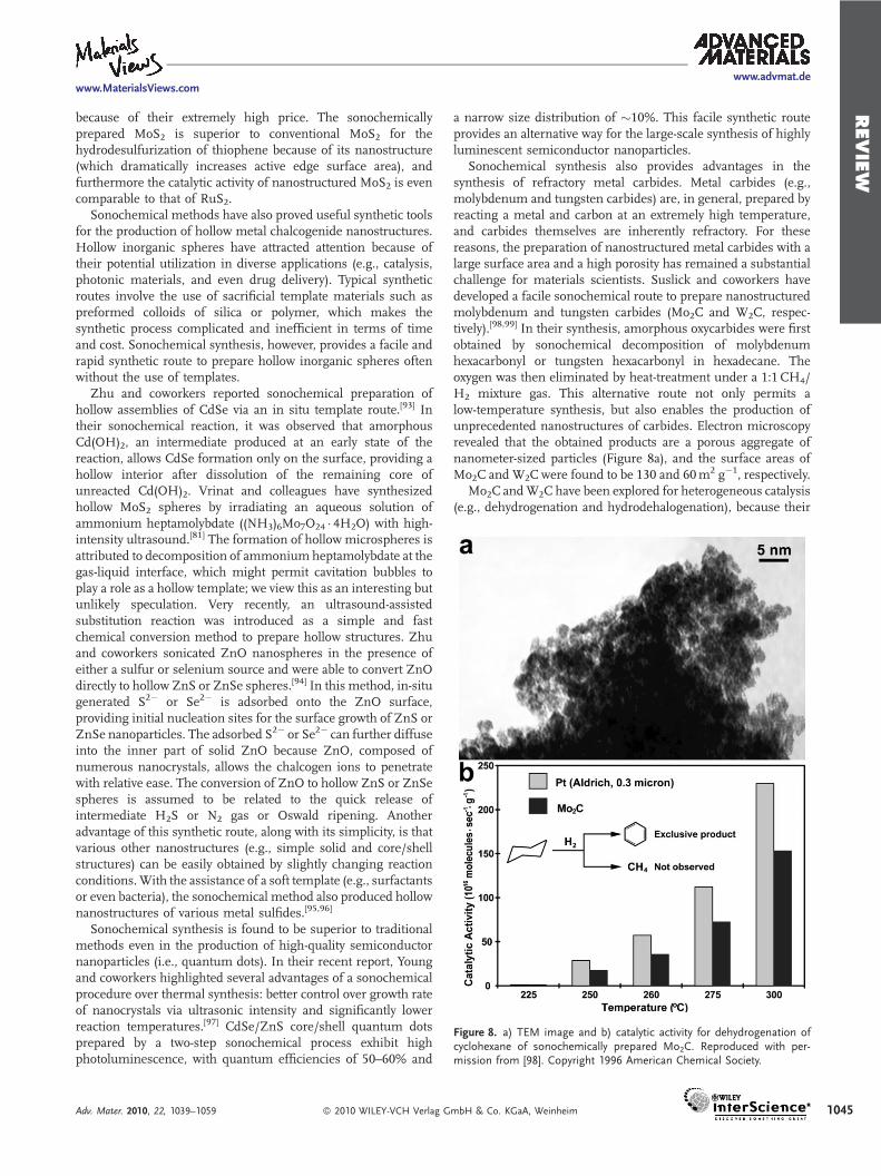
Figure 8. a) TEM image and b) catalytic activity for dehydrogenation ofcyclohexane of sonochemically prepared Mo2C. Reproduced with per-mission from [98]. Copyright 1996 American Chemical Society.
because of their extremely high price. The sonochemicallyprepared MoS2 is superior to conventional MoS2 for thehydrodesulfurization of thiophene because of its nanostructure(which dramatically increases active edge surface area), andfurthermore the catalytic activity of nanostructured MoS2 is evencomparable to that of RuS2.
Sonochemical methods have also proved useful synthetic toolsfor the production of hollow metal chalcogenide nanostructures.Hollow inorganic spheres have attracted attention because oftheir potential utilization in diverse applications (e.g., catalysis,photonic materials, and even drug delivery). Typical syntheticroutes involve the use of sacrificial template materials such aspreformed colloids of silica or polymer, which makes thesynthetic process complicated and inefficient in terms of timeand cost. Sonochemical synthesis, however, provides a facile andrapid synthetic route to prepare hollow inorganic spheres oftenwithout the use of templates.
Zhu and coworkers reported sonochemical preparation ofhollow assemblies of CdSe via an in situ template route.[93] Intheir sonochemical reaction, it was observed that amorphousCd(OH)2, an intermediate produced at an early state of thereaction, allows CdSe formation only on the surface, providing ahollow interior after dissolution of the remaining core ofunreacted Cd(OH)2. Vrinat and colleagues have synthesizedhollow MoS2 spheres by irradiating an aqueous solution ofammonium heptamolybdate ((NH3)6Mo7O24 � 4H2O) with high-intensity ultrasound.[81] The formation of hollow microspheres isattributed to decomposition of ammonium heptamolybdate at thegas-liquid interface, which might permit cavitation bubbles toplay a role as a hollow template; we view this as an interesting butunlikely speculation. Very recently, an ultrasound-assistedsubstitution reaction was introduced as a simple and fastchemical conversion method to prepare hollow structures. Zhuand coworkers sonicated ZnO nanospheres in the presence ofeither a sulfur or selenium source and were able to convert ZnOdirectly to hollow ZnS or ZnSe spheres.[94] In this method, in-situgenerated S2� or Se2� is adsorbed onto the ZnO surface,providing initial nucleation sites for the surface growth of ZnS orZnSe nanoparticles. The adsorbed S2� or Se2� can further diffuseinto the inner part of solid ZnO because ZnO, composed ofnumerous nanocrystals, allows the chalcogen ions to penetratewith relative ease. The conversion of ZnO to hollow ZnS or ZnSespheres is assumed to be related to the quick release ofintermediate H2S or N2 gas or Oswald ripening. Anotheradvantage of this synthetic route, along with its simplicity, is thatvarious other nanostructures (e.g., simple solid and core/shellstructures) can be easily obtained by slightly changing reactionconditions.With the assistance of a soft template (e.g., surfactantsor even bacteria), the sonochemical method also produced hollownanostructures of various metal sulfides.[95,96]
Sonochemical synthesis is found to be superior to traditionalmethods even in the production of high-quality semiconductornanoparticles (i.e., quantum dots). In their recent report, Youngand coworkers highlighted several advantages of a sonochemicalprocedure over thermal synthesis: better control over growth rateof nanocrystals via ultrasonic intensity and significantly lowerreaction temperatures.[97] CdSe/ZnS core/shell quantum dotsprepared by a two-step sonochemical process exhibit highphotoluminescence, with quantum efficiencies of 50–60% and
Adv. Mater. 2010, 22, 1039–1059 � 2010 WILEY-VCH Verlag G
a narrow size distribution of �10%. This facile synthetic routeprovides an alternative way for the large-scale synthesis of highlyluminescent semiconductor nanoparticles.
Sonochemical synthesis also provides advantages in thesynthesis of refractory metal carbides. Metal carbides (e.g.,molybdenum and tungsten carbides) are, in general, prepared byreacting a metal and carbon at an extremely high temperature,and carbides themselves are inherently refractory. For thesereasons, the preparation of nanostructured metal carbides with alarge surface area and a high porosity has remained a substantialchallenge for materials scientists. Suslick and coworkers havedeveloped a facile sonochemical route to prepare nanostructuredmolybdenum and tungsten carbides (Mo2C and W2C, respec-tively).[98,99] In their synthesis, amorphous oxycarbides were firstobtained by sonochemical decomposition of molybdenumhexacarbonyl or tungsten hexacarbonyl in hexadecane. Theoxygen was then eliminated by heat-treatment under a 1:1 CH4/H2 mixture gas. This alternative route not only permits alow-temperature synthesis, but also enables the production ofunprecedented nanostructures of carbides. Electron microscopyrevealed that the obtained products are a porous aggregate ofnanometer-sized particles (Figure 8a), and the surface areas ofMo2C and W2Cwere found to be 130 and 60m2 g�1, respectively.
Mo2C andW2C have been explored for heterogeneous catalysis(e.g., dehydrogenation and hydrodehalogenation), because their
mbH & Co. KGaA, Weinheim 1045
REVIE
W
www.advmat.dewww.MaterialsViews.com
1046
catalytic activities are comparable to those of platinum groupmetals. For instance, sonochemically produced Mo2Cwas provento be an excellent dehydrogenation catalyst, with activity andselectivity comparable to those of Pt metal (Figure 8b).[98] Inaddition, nanostructured molybdenum and tungsten carbidesprepared by the sonochemical route show superior activity,selectivity, and stability for hydrodehalogenation of halogenatedorganic pollutants.[99]
2.2.4. Nanostructured Materials via Sonochemical Deposition
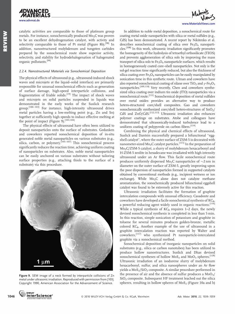
The physical effects of ultrasound (e.g., ultrasound-induced shockwaves and microjets at the liquid–solid interface) are primarilyresponsible for unusual sonochemical effects such as generationof surface damage, high-speed interparticle collisions, andfragmentation of friable solids.[19] The impact of shock wavesand microjets on solid particles suspended in liquids wasdemonstrated in the early works of the Suslick researchgroup.[100–103] For instance, high-intensity ultrasound drivesmetal particles having a low-melting point (e.g., Zn and Sn)together at sufficiently high speeds to induce effective melting atthe point of impact (Figure 9).[103,104]
The physical effects of ultrasound have often been utilized todeposit nanoparticles onto the surface of substrates. Gedankenand coworkers reported sonochemical deposition of in-situgenerated noble metal nanoparticles on various substrates (e.g.,silica, carbon, or polymer).[105–107] This sonochemical processsignificantly reduces the reaction time, achieving uniform coatingof nanoparticles on substrates. Also, noble metal nanoparticlescan be easily anchored on various substrates without tailoringsurface properties (e.g., attaching thiols to the surface of asubstrate) via this procedure.
Figure 9. SEM image of a neck formed by interparticle collisions of Znmetal under ultrasonic irradiation. Reproduced with permission from [103].Copyright 1990, American Association for the Advancement of Science.
� 2010 WILEY-VCH Verlag Gmb
In addition to noble metal deposition, a sonochemical route forcoating metal oxide nanoparticles with silica or metal sulfides (e.g.,CdS) has been demonstrated. A recent report by Nikitenko et al.describes sonochemical coating of silica over Fe3O4 nanoparti-cles.[108] In this work, ultrasonic irradiation significantly promotesthe homogeneity of the hydrolysis of tetraethyl orthosilicate (TEOS)and prevents agglomeration of silica sols by improving the masstransport of silica sols to Fe3O4 nanoparticle surfaces, which resultsin homogeneously coated core–shell nanoparticles. Not only is thesol-gel reaction time significantly reduced, but also the thickness ofsilica coating over Fe3O4 nanoparticles can be easily manipulated bysonication time in this synthetic route. Ulman and coworkers havealso reported sonochemical coating of silane over TiO2 and g-Fe2O3
nanoparticles.[109,110] Very recently, Chen and coworkers synthe-sized silica coating over indium tin oxide (ITO) nanoparticles via asonochemical route.[111] Sonochemical deposition of metal sulfidesover metal oxides provides an alternative way to producehetero-structured core/shell composites. Gao and coworkerssonochemically synthesized core/shell hetero-structures of SnO2/CdS and ZnO/CdS.[112,113] Ultrasonic irradiation also enhancespolymer coatings on substrates. Atobe and colleagues havedemonstrated that ultrasonically-induced turbulence lead to auniform coating of polypyrrole on carbon fibers.[114]
Combining the physical and chemical effects of ultrasound,Suslick and Dantsin successfully prepared a bifunctional ‘‘egg-shell catalyst’’, where the outer surface of ZSM-5 is decorated withnanometer-sizedMo2C catalyst particles.[115] In the preparation ofMo2C/ZSM-5 catalyst, a slurry of molybdenum hexacarbonyl andH-ZSM-5 zeolite in hexadecane was irradiated with high intensityultrasound under an Ar flow. This facile sonochemical routeproduces uniformly dispersed Mo2C nanoparticles of �2 nm indiameter on the outer surface of ZSM-5, greatly improving uponthe poor dispersion of nanoparticles formed in supported catalystsobtained by conventional methods (e.g., incipient wetness or ionexchange). While Mo2C alone does not catalyze methanearomatization, the sonochemically produced bifunctional eggshellcatalyst was found to be extremely active for this reaction.
Ultrasonic irradiation facilitates the formation of graphiteintercalation compounds with unusual efficiency. Casadonte andcoworkers have developed a facile sonochemical synthesis of KC8,a powerful reducing agent widely used in organic reactions.[116]
While a typical synthesis of KC8 requires 1–2 days, the newlydevised sonochemical synthesis is completed in less than 5min.In this reaction, simple sonication of potassium and graphite intoluene for several minutes produces golden-bronze, metalliccolored KC8. Another example of the use of ultrasound in agraphite intercalation reaction was reported by Walter andcoworkers,[117] who synthesized Pt nanoparticle-intercalatedgraphite via a sonochemical method.
Sonochemical deposition of inorganic nanoparticles on solidsubstrates (e.g., silica or carbon nanotubes) has been utilized toproduce hollow nanostructures. Suslick and Dhas devisedsonochemical syntheses of hollow MoS2 and MoO3 spheres.
[118]
Ultrasonic irradiation of an isodurene slurry of molybdenumhexacarbonyl, sulfur, and silica nanospheres under an Ar flowyields a MoS2/SiO2 composite. A similar procedure performed inthe presence of air and the absence of sulfur produces a MoO3/SiO2 composite. Subsequent HF treatment leached out the silicaspheres, resulting in hollow spheres of MoS2 (Figure 10a and b)
H & Co. KGaA, Weinheim Adv. Mater. 2010, 22, 1039–1059
REVIE
W
www.MaterialsViews.comwww.advmat.de
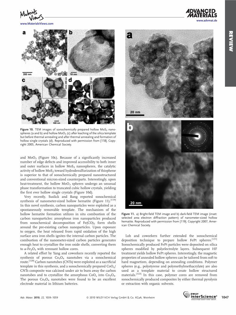
Figure 10. TEM images of sonochemically prepared hollow MoS2 nano-spheres (a and b) and hollow MoO3 (c) after leaching of the silica templatebut before thermal annealing and after thermal annealing and formation ofhollow single crystals (d). Reproduced with permission from [118]. Copy-right 2005, American Chemical Society.
Figure 11. a) Bright-field TEM image and b) dark-field TEM image (inset:selected area electron diffraction pattern) of nanometer-sized hollowhematite. Reproduced with permission from [119]. Copyright 2007, Amer-ican Chemical Society.
and MoO3 (Figure 10c). Because of a significantly increasednumber of edge defects and improved accessibility to both innerand outer surfaces in hollow MoS2 nanospheres, the catalyticactivity of hollowMoS2 toward hydrodesulfurization of thiopheneis superior to that of sonochemically prepared nanostructuredand conventional micron-sized counterparts. Interestingly, uponheat-treatment, the hollow MoO3 spheres undergo an unusualphase transformation to truncated cubic hollow crystals, yieldingthe first ever hollow single crystals (Figure 10d).
Very recently, Suslick and Bang reported sonochemicalsynthesis of nanometer-sized hollow hematite (Figure 11).[119]
In this novel synthesis, carbon nanoparticles were exploited as aspontaneously removable template. The mechanism of thehollow hematite formation utilizes in situ combustion of thecarbon nanoparticles: amorphous iron nanoparticles producedfrom sonochemical decomposition of Fe(CO)5 form shellsaround the pre-existing carbon nanoparticles. Upon exposureto oxygen, the heat released from rapid oxidation of the highsurface area iron shells ignites the internal carbon particles. Thecombustion of the nanometer-sized carbon particles generatesenough heat to crystallize the iron oxide shells, converting themto a-Fe2O3 with remnant hollow cores.
A related effort by Yang and coworkers recently reported thesynthesis of porous Co3O4 nanotubes via a sonochemicalroute.[120] Carbon nanotubes (CNTs) were exploited as a sacrificialtemplate in this synthesis, and a sonochemically prepared CoOx/CNTs composite was calcined under air to burn away the carbonnanotubes and to crystallize the amorphous CoOx into Co3O4.The porous Co3O4 nanotubes were found to be an excellentelectrode material in lithium batteries.
Adv. Mater. 2010, 22, 1039–1059 � 2010 WILEY-VCH Verlag G
Loh and coworkers further extended the sonochemicaldeposition technique to prepare hollow FePt spheres.[121]
Sonochemically produced FePt particles were deposited on silicaspheres modified by polyelectrolyte layers. Subsequent HFtreatment yields hollow FePt spheres. Interestingly, the magneticproperties of annealed hollow spheres can be tailored from soft tohard magnetism, depending on annealing conditions. Polymerspheres (e.g., polystyrene and polymethylmethacrylate) are alsoused as a template material to create hollow structuredmaterials.[122] In this case, polymer cores are removed fromsonochemically produced composites by either thermal pyrolysisor extraction with organic solvents.
mbH & Co. KGaA, Weinheim 1047
REVIE
W
www.advmat.dewww.MaterialsViews.com
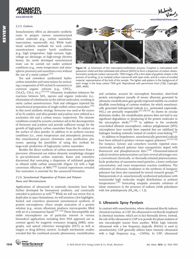
Figure 12. a) Schematic of the intercalation/exfoliation process. Graphite is intercalated withpotassium metal and then exfoliated with ethanol (EtOH) to form a dispersion of carbon sheets.Sonication produces carbon nanoscrolls. TEM images of b) a thin plate of graphitic sheets in theprocess of scrolling, c) an isolated carbon nanoscroll with open ends, and d) a mass of scrolledmaterial, representative of the bulk of the sample. The lighter web pattern in the background ofeach image is the lacey carbon TEM grid. Reproduced with permission from [126]. Copyright2003, AAAS.
1048
2.2.5. Carbons
Sonochemistry offers an alternative syntheticroute to prepare various nanostructuredcarbon materials (e.g., carbon nanotubes,nano-onions, nanoscrolls, etc). While tradi-tional synthetic methods for such carbonnanostructures require harsh conditions(e.g., high temperature, high vacuum, high-voltage arc discharge, or high-energy electronbeam), the newly developed sonochemicalroute can be carried out under ambientconditions (e.g., room temperature and atmo-spheric pressure) and sometimes even withoutthe use of a metal catalyst.[123]
Teo and coworkers synthesized hydro-carbon nanotubes and nano-onions by sonicat-ing a suspension of HF-etched Si nanowires incommon organic solvents (e.g., CHCl3,
CH2Cl2, CH3I, etc.).[123,124] Ultrasonic irradiation enhances thereactions between SiHx species and organic molecules (i.e.,elimination of substituents on the solventmolecules), resulting inexotic carbon nanostructures. Park and colleagues reported thesonochemical preparation of single-walled carbon nanotubes.[125]
In this novel synthetic strategy, ferrocene was used as the sourceof an Fe catalyst, and silica powder and p-xylene were utilized as anucleation site and a carbon source, respectively. The extremeconditions created by acoustic cavitation aid in the decompositionof ferrocene and p-xylene and provide sufficient energy for thegrowth of high-purity carbon nanotubes from the Fe catalyst onthe surface of silica powder. In addition to its ambient reactionconditions (i.e., room temperature and atmospheric pressure),this sonochemical process eliminates extra purification pro-cesses, opening the possibility of using this method forlarge-scale production of high-purity carbon nanotubes.
Besides the direct synthesis of carbon nanostructures from aprecursor, ultrasound can induce dramatic morphology changesin pre-synthesized carbon materials. Kaner and coworkersdiscovered that sonicating a dispersion of exfoliated graphitein ethanol yields carbon nanoscrolls (Figure 12) with a highconversion efficiency of 80%.[126] Control experiments revealedthat sonication is essential for the nanoscroll formation.
2.2.6. Sonochemical Preparation of Protein and Polymer
Nano and Microstructures
Applications of ultrasound to materials chemistry have beenfurther developed for biomaterial synthesis, and continuallyextended to polymers as well.[19] While we will not review this indepth (due to space limitations), we will mention a few highlights.Suslick and coworkers pioneered sonochemical synthesis ofprotein microspheres, where simple sonication of a proteinsolution (e.g., serum albumins) produces microcapsules filledwith air or a nonaqueous liquid.[127–134] These biocompatible andstable microspheres are of particular interest in variousbiomedical applications including their FDA approved use ascontrast agents for magnetic resonance imaging (MRI), sono-graphy, and optical coherence tomography (OCT) as well asoxygen or drug delivery carriers. In-depth mechanistic studiesrevealed that the combined acoustic phenomena, emulsification
� 2010 WILEY-VCH Verlag Gmb
and cavitation, account for microsphere formation: short-livedprotein microspheres (usually of serum albumin) generated byultrasonic emulsification gain greatly improved stability via covalentdisulfide cross-linking of cysteine residues, for which sonochemi-cally generated hydroperoxyl radicals (i.e., protonated superoxide,HO2�) are primarily responsible.[127,128,133] As shown by circulardichroism studies, the emulsification process does not lead to anysignificant degradation or denaturing of the protein molecules inthe microsphere shells.[127,128] In addition to the covalentlycross-linked albumin microspheres, sodium polyglutamate (SPG)microspheres have recently been reported that are stabilized byhydrogen bonding networks instead of covalent cross-linking.[134]
In addition to biopolymers, sonochemically generated radicalshave been utilized to produce various organic polymers.[19,135,136]
For instance, Grieser and coworkers recently reported sono-chemically produced polymer latex nanoparticles doped withfluorescent and phosphorescent dyes.[136] Ultrasound-inducedradical emulsion polymerization can have several advantages overa conventional chemically- or thermally-initiated polymerization:facile production of nanometer-sized particles, a lower surfactantconcentration, and room temperature reaction conditions. Theutilization of ultrasonic irradiation in the synthesis of inorganicpolymers has been also examined by several research groups.[19]
Matyjaszewski et al. sonochemically synthesized polysilanes withmonomodal high molecular weight distributions at ambienttemperatures.[137] Sonicating nonpolar aromatic solutions ofsilane monomers in the presence of sodium yields polysilaneswith low polydispersity (Mw/Mn< 1.2).
3. Ultrasonic Spray Pyrolysis
In contrast with sonochemistry, where ultrasound directly induceschemical reactions, in USP, the ultrasound is not directly employedin chemical reactions, which are in fact thermally driven. Instead,the role of the ultrasound inUSP is to provide the phase isolation ofone microdroplet reactor from another. While high intensityultrasound with a low frequency (typically 20 kHz) is used insonochemistry, USP generally utilizes lower intensity ultrasoundwith a high frequency (e.g., �2MHz). In USP, ultrasound
H & Co. KGaA, Weinheim Adv. Mater. 2010, 22, 1039–1059
REVIE
W
www.MaterialsViews.comwww.advmat.de
nebulizes precursor solutions to produce themicron-sized dropletsthat act as isolated, individualmicron-sized chemical reactors. Bothcavitation-induced sonochemistry and USP, in general, areinvolved phase-separated (i.e., two- and sometimes multi- phase)chemical reactions. InUSP, liquid droplets generated by ultrasonicnebulization are heated in a gas flow, and subsequently solid-phaseor sometimes liquid-phase (when precursors melt prior todecomposition or when high boiling point liquids are used)chemical reactions occur. The major differences between twosynthetic methods are summarized in Table 1.
Spray pyrolysis has been widely used in industry for ultrafine-and nanoparticle production as well as film deposition, in partbecause the apparatus is simple and continuous and can be scaledeasily for mass production. In general, spray pyrolysis involvesthe thermal decomposition of aerosols (i.e., solid or liquidparticles suspended in a gas) generated by an nebulizer (e.g.,pneumatic, ultrasonic, or electrostatic nebulizers) in a gasflow.[138] Among the various nebulization techniques, the use ofultrasonic nebulizers has been favored because of their out-standing energy-efficiency in aerosol generation over othernebulization tools, affordability (e.g., the use of householdhumidifiers), and the inherently low velocity of the initial aerosol.As a synthetic tool, USP has several advantages over othertraditional methods: production of micron- or submicron-sizedspherical particles, high product purity, continuous operation,and ease of controlling composition.[138–140] Unlike conventionalsolid- or liquid-phase synthetic methods (e.g., precipitation,hydrothermal method, and solid-state reaction) where batchreactions are performed to produce materials, the USP techniqueis a continuous flow process that enables both large and smallscale production of products with excellent reproducibility. Inaddition, the facile control over chemical and physical composi-tions in the USP method makes USP particularly useful in thepreparation of multicomponent or composite materials.[138]
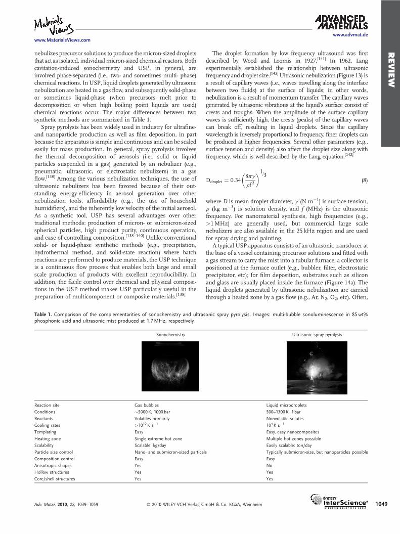
Table 1. Comparison of the complementarities of sonochemistry and ultrasphosphonic acid and ultrasonic mist produced at 1.7MHz, respectively.
Sonochemistry
Reaction site Gas bubbles
Conditions �5000 K, 1000 bar
Reactants Volatiles primarily
Cooling rates >1010 K s�1
Templating Easy
Heating zone Single extreme hot zone
Scalability Scalable: kg/day
Particle size control Nano- and submicron-sized particel
Composition control Easy
Anisotropic shapes Yes
Hollow structures Yes
Core/shell structures Yes
Adv. Mater. 2010, 22, 1039–1059 � 2010 WILEY-VCH Verlag G
The droplet formation by low frequency ultrasound was firstdescribed by Wood and Loomis in 1927.[141] In 1962, Langexperimentally established the relationship between ultrasonicfrequency and droplet size.[142] Ultrasonic nebulization (Figure 13) isa result of capillary waves (i.e., waves travelling along the interfacebetween two fluids) at the surface of liquids; in other words,nebulization is a result of momentum transfer. The capillary wavesgenerated by ultrasonic vibrations at the liquid’s surface consist ofcrests and troughs. When the amplitude of the surface capillarywaves is sufficiently high, the crests (peaks) of the capillary wavescan break off, resulting in liquid droplets. Since the capillarywavelength is inversely proportional to frequency, finer droplets canbe produced at higher frequencies. Several other parameters (e.g.,surface tension and density) also affect the droplet size along withfrequency, which is well-described by the Lang equation:[142]
Ddroplet ¼ 0:348pg
rf 2
� �1=3(8)
where D is mean droplet diameter, g (N m�1) is surface tension,r (kg m�3) is solution density, and f (MHz) is the ultrasonicfrequency. For nanomaterial synthesis, high frequencies (e.g.,>1MHz) are generally used, but commercial large scalenebulizers are also available in the 25 kHz region and are usedfor spray drying and painting.
A typical USP apparatus consists of an ultrasonic transducer atthe base of a vessel containing precursor solutions and fitted witha gas stream to carry the mist into a tubular furnace; a collector ispositioned at the furnace outlet (e.g., bubbler, filter, electrostaticprecipitator, etc); for film deposition, substrates such as siliconand glass are usually placed inside the furnace (Figure 14a). Theliquid droplets generated by ultrasonic nebulization are carriedthrough a heated zone by a gas flow (e.g., Ar, N2, O2, etc). Often,
onic spray pyrolysis. Images: multi-bubble sonoluminescence in 85wt%
Ultrasonic spray pyrolysis
Liquid microdroplets
500–1300 K, 1 bar
Nonvolatile solutes
104 K s�1
Easy, easy nanocomposites
Multiple hot zones possible
Easily scalable: ton/day
s Typically submicron-size, but nanoparticles possible
Easy
No
Yes
Yes
mbH & Co. KGaA, Weinheim 1049
REVIE
W
www.advmat.dewww.MaterialsViews.com
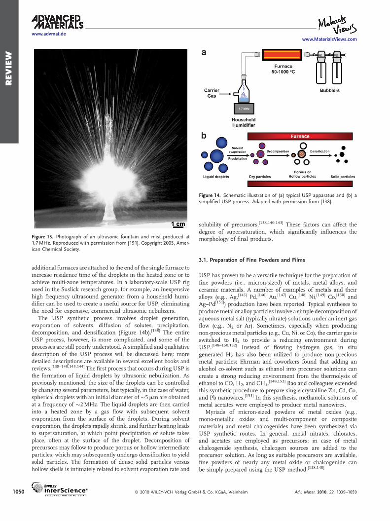
Figure 14. Schematic illustration of (a) typical USP apparatus and (b) asimplified USP process. Adapted with permission from [138].
Figure 13. Photograph of an ultrasonic fountain and mist produced at1.7MHz. Reproduced with permission from [191]. Copyright 2005, Amer-ican Chemical Society.
1050
additional furnaces are attached to the end of the single furnace toincrease residence time of the droplets in the heated zone or toachieve multi-zone temperatures. In a laboratory-scale USP rigused in the Suslick research group, for example, an inexpensivehigh frequency ultrasound generator from a household humi-difier can be used to create a useful source for USP, eliminatingthe need for expensive, commercial ultrasonic nebulizers.
The USP synthetic process involves droplet generation,evaporation of solvents, diffusion of solutes, precipitation,decomposition, and densification (Figure 14b).[138] The entireUSP process, however, is more complicated, and some of theprocesses are still poorly understood. A simplified and qualitativedescription of the USP process will be discussed here; moredetailed descriptions are available in several excellent books andreviews.[138–140,143,144] The first process that occurs during USP isthe formation of liquid droplets by ultrasonic nebulization. Aspreviously mentioned, the size of the droplets can be controlledby changing several parameters, but typically, in the case of water,spherical droplets with an initial diameter of �5mm are obtainedat a frequency of �2MHz. The liquid droplets are then carriedinto a heated zone by a gas flow with subsequent solventevaporation from the surface of the droplets. During solventevaporation, the droplets rapidly shrink, and further heating leadsto supersaturation, at which point precipitation of solute takesplace, often at the surface of the droplet. Decomposition ofprecursors may follow to produce porous or hollow intermediateparticles, which may subsequently undergo densification to yieldsolid particles. The formation of dense solid particles versushollow shells is intimately related to solvent evaporation rate and
� 2010 WILEY-VCH Verlag Gmb
solubility of precursors.[138,140,143] These factors can affect thedegree of supersaturation, which significantly influences themorphology of final products.
3.1. Preparation of Fine Powders and Films
USP has proven to be a versatile technique for the preparation offine powders (i.e., micron-sized) of metals, metal alloys, andceramic materials. A number of examples of metals and theiralloys (e.g., Ag,[145] Pd,[146] Au,[147] Cu,[148] Ni,[149] Co,[150] andAg–Pd[151]) production have been reported. Typical syntheses toproducemetal or alloy particles involve a simple decomposition ofaqueous metal salt (typically nitrate) solutions under an inert gasflow (e.g., N2 or Ar). Sometimes, especially when producingnon-preciousmetal particles (e.g., Cu, Ni, or Co), the carrier gas isswitched to H2 to provide a reducing environment duringUSP.[148–150,152] Instead of flowing hydrogen gas, in situgenerated H2 has also been utilized to produce non-preciousmetal particles; Ehrman and coworkers found that adding analcohol co-solvent such as ethanol into precursor solutions cancreate a strong reducing environment from the thermolysis ofethanol to CO, H2, and CH4.
[148,152] Rao and colleagues extendedthis synthetic procedure to prepare single crystalline Zn, Cd, Co,and Pb nanowires.[153] In this synthesis, methanolic solutions ofmetal acetates were employed to produce metal nanowires.
Myriads of micron-sized powders of metal oxides (e.g.,mono-metallic oxides and multi-component or compositematerials) and metal chalcogenides have been synthesized viaUSP synthetic routes. In general, metal nitrates, chlorates,and acetates are employed as precursors; in case of metalchalcogenide synthesis, chalcogen sources are added to theprecursor solution. As long as suitable precursors are available,fine powders of nearly any metal oxide or chalcogenide canbe simply prepared using the USP method.[138,140]
H & Co. KGaA, Weinheim Adv. Mater. 2010, 22, 1039–1059
REVIE
W
www.MaterialsViews.comwww.advmat.de
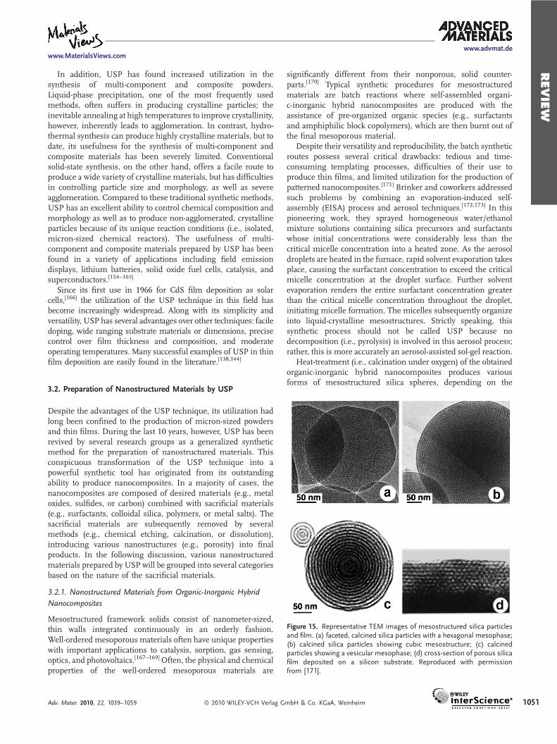
Figure 15. Representative TEM images of mesostructured silica particlesand film. (a) faceted, calcined silica particles with a hexagonal mesophase;(b) calcined silica particles showing cubic mesostructure; (c) calcinedparticles showing a vesicular mesophase; (d) cross-section of porous silicafilm deposited on a silicon substrate. Reproduced with permissionfrom [171].
In addition, USP has found increased utilization in thesynthesis of multi-component and composite powders.Liquid-phase precipitation, one of the most frequently usedmethods, often suffers in producing crystalline particles; theinevitable annealing at high temperatures to improve crystallinity,however, inherently leads to agglomeration. In contrast, hydro-thermal synthesis can produce highly crystalline materials, but todate, its usefulness for the synthesis of multi-component andcomposite materials has been severely limited. Conventionalsolid-state synthesis, on the other hand, offers a facile route toproduce a wide variety of crystalline materials, but has difficultiesin controlling particle size and morphology, as well as severeagglomeration. Compared to these traditional synthetic methods,USP has an excellent ability to control chemical composition andmorphology as well as to produce non-agglomerated, crystallineparticles because of its unique reaction conditions (i.e., isolated,micron-sized chemical reactors). The usefulness of multi-component and composite materials prepared by USP has beenfound in a variety of applications including field emissiondisplays, lithium batteries, solid oxide fuel cells, catalysis, andsuperconductors.[154–165]
Since its first use in 1966 for CdS film deposition as solarcells,[166] the utilization of the USP technique in this field hasbecome increasingly widespread. Along with its simplicity andversatility, USP has several advantages over other techniques: faciledoping, wide ranging substrate materials or dimensions, precisecontrol over film thickness and composition, and moderateoperating temperatures. Many successful examples of USP in thinfilm deposition are easily found in the literature.[138,144]
3.2. Preparation of Nanostructured Materials by USP
Despite the advantages of the USP technique, its utilization hadlong been confined to the production of micron-sized powdersand thin films. During the last 10 years, however, USP has beenrevived by several research groups as a generalized syntheticmethod for the preparation of nanostructured materials. Thisconspicuous transformation of the USP technique into apowerful synthetic tool has originated from its outstandingability to produce nanocomposites. In a majority of cases, thenanocomposites are composed of desired materials (e.g., metaloxides, sulfides, or carbon) combined with sacrificial materials(e.g., surfactants, colloidal silica, polymers, or metal salts). Thesacrificial materials are subsequently removed by severalmethods (e.g., chemical etching, calcination, or dissolution),introducing various nanostructures (e.g., porosity) into finalproducts. In the following discussion, various nanostructuredmaterials prepared by USP will be grouped into several categoriesbased on the nature of the sacrificial materials.
3.2.1. Nanostructured Materials from Organic-Inorganic Hybrid
Nanocomposites
Mesostructured framework solids consist of nanometer-sized,thin walls integrated continuously in an orderly fashion.Well-ordered mesoporous materials often have unique propertieswith important applications to catalysis, sorption, gas sensing,optics, and photovoltaics.[167–169] Often, the physical and chemicalproperties of the well-ordered mesoporous materials are
Adv. Mater. 2010, 22, 1039–1059 � 2010 WILEY-VCH Verlag G
significantly different from their nonporous, solid counter-parts.[170] Typical synthetic procedures for mesostructuredmaterials are batch reactions where self-assembled organi-c-inorganic hybrid nanocomposites are produced with theassistance of pre-organized organic species (e.g., surfactantsand amphiphilic block copolymers), which are then burnt out ofthe final mesoporous material.
Despite their versatility and reproducibility, the batch syntheticroutes possess several critical drawbacks: tedious and time-consuming templating processes, difficulties of their use toproduce thin films, and limited utilization for the production ofpatterned nanocomposites.[171] Brinker and coworkers addressedsuch problems by combining an evaporation-induced self-assembly (EISA) process and aerosol techniques.[172,173] In thispioneering work, they sprayed homogeneous water/ethanolmixture solutions containing silica precursors and surfactantswhose initial concentrations were considerably less than thecritical micelle concentration into a heated zone. As the aerosoldroplets are heated in the furnace, rapid solvent evaporation takesplace, causing the surfactant concentration to exceed the criticalmicelle concentration at the droplet surface. Further solventevaporation renders the entire surfactant concentration greaterthan the critical micelle concentration throughout the droplet,initiating micelle formation. The micelles subsequently organizeinto liquid-crystalline mesostructures. Strictly speaking, thissynthetic process should not be called USP because nodecomposition (i.e., pyrolysis) is involved in this aerosol process;rather, this is more accurately an aerosol-assisted sol-gel reaction.
Heat-treatment (i.e., calcination under oxygen) of the obtainedorganic-inorganic hybrid nanocomposites produces variousforms of mesostructured silica spheres, depending on the
mbH & Co. KGaA, Weinheim 1051
REVIE
W
www.advmat.dewww.MaterialsViews.com
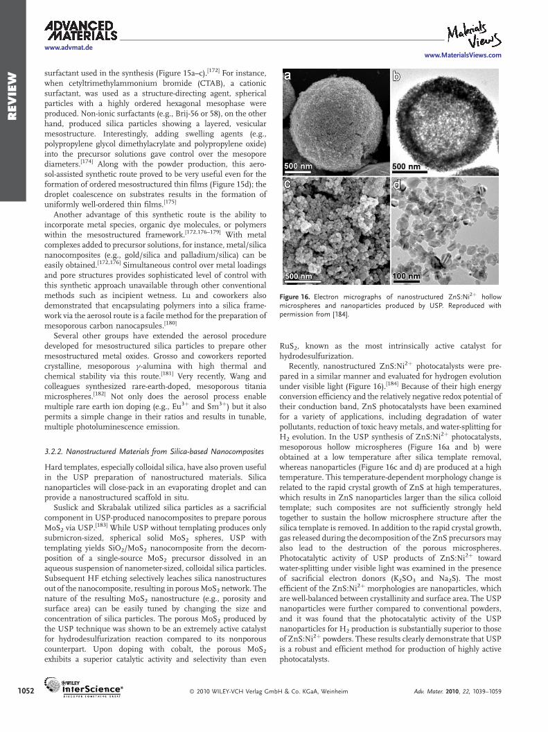
Figure 16. Electron micrographs of nanostructured ZnS:Ni2þ hollowmicrospheres and nanoparticles produced by USP. Reproduced withpermission from [184].
1052
surfactant used in the synthesis (Figure 15a–c).[172] For instance,when cetyltrimethylammonium bromide (CTAB), a cationicsurfactant, was used as a structure-directing agent, sphericalparticles with a highly ordered hexagonal mesophase wereproduced. Non-ionic surfactants (e.g., Brij-56 or 58), on the otherhand, produced silica particles showing a layered, vesicularmesostructure. Interestingly, adding swelling agents (e.g.,polypropylene glycol dimethylacrylate and polypropylene oxide)into the precursor solutions gave control over the mesoporediameters.[174] Along with the powder production, this aero-sol-assisted synthetic route proved to be very useful even for theformation of ordered mesostructured thin films (Figure 15d); thedroplet coalescence on substrates results in the formation ofuniformly well-ordered thin films.[175]
Another advantage of this synthetic route is the ability toincorporate metal species, organic dye molecules, or polymerswithin the mesostructured framework.[172,176–179] With metalcomplexes added to precursor solutions, for instance, metal/silicananocomposites (e.g., gold/silica and palladium/silica) can beeasily obtained.[172,176] Simultaneous control over metal loadingsand pore structures provides sophisticated level of control withthis synthetic approach unavailable through other conventionalmethods such as incipient wetness. Lu and coworkers alsodemonstrated that encapsulating polymers into a silica frame-work via the aerosol route is a facile method for the preparation ofmesoporous carbon nanocapsules.[180]
Several other groups have extended the aerosol proceduredeveloped for mesostructured silica particles to prepare othermesostructured metal oxides. Grosso and coworkers reportedcrystalline, mesoporous g -alumina with high thermal andchemical stability via this route.[181] Very recently, Wang andcolleagues synthesized rare-earth-doped, mesoporous titaniamicrospheres.[182] Not only does the aerosol process enablemultiple rare earth ion doping (e.g., Eu3þ and Sm3þ) but it alsopermits a simple change in their ratios and results in tunable,multiple photoluminescence emission.
3.2.2. Nanostructured Materials from Silica-based Nanocomposites
Hard templates, especially colloidal silica, have also proven usefulin the USP preparation of nanostructured materials. Silicananoparticles will close-pack in an evaporating droplet and canprovide a nanostructured scaffold in situ.
Suslick and Skrabalak utilized silica particles as a sacrificialcomponent in USP-produced nanocomposites to prepare porousMoS2 via USP.[183] While USP without templating produces onlysubmicron-sized, spherical solid MoS2 spheres, USP withtemplating yields SiO2/MoS2 nanocomposite from the decom-position of a single-source MoS2 precursor dissolved in anaqueous suspension of nanometer-sized, colloidal silica particles.Subsequent HF etching selectively leaches silica nanostructuresout of the nanocomposite, resulting in porousMoS2 network. Thenature of the resulting MoS2 nanostructure (e.g., porosity andsurface area) can be easily tuned by changing the size andconcentration of silica particles. The porous MoS2 produced bythe USP technique was shown to be an extremely active catalystfor hydrodesulfurization reaction compared to its nonporouscounterpart. Upon doping with cobalt, the porous MoS2exhibits a superior catalytic activity and selectivity than even
� 2010 WILEY-VCH Verlag Gmb
RuS2, known as the most intrinsically active catalyst forhydrodesulfurization.
Recently, nanostructured ZnS:Ni2þ photocatalysts were pre-pared in a similar manner and evaluated for hydrogen evolutionunder visible light (Figure 16).[184] Because of their high energyconversion efficiency and the relatively negative redox potential oftheir conduction band, ZnS photocatalysts have been examinedfor a variety of applications, including degradation of waterpollutants, reduction of toxic heavy metals, and water-splitting forH2 evolution. In the USP synthesis of ZnS:Ni2þ photocatalysts,mesoporous hollow microspheres (Figure 16a and b) wereobtained at a low temperature after silica template removal,whereas nanoparticles (Figure 16c and d) are produced at a hightemperature. This temperature-dependent morphology change isrelated to the rapid crystal growth of ZnS at high temperatures,which results in ZnS nanoparticles larger than the silica colloidtemplate; such composites are not sufficiently strongly heldtogether to sustain the hollow microsphere structure after thesilica template is removed. In addition to the rapid crystal growth,gas released during the decomposition of the ZnS precursorsmayalso lead to the destruction of the porous microspheres.Photocatalytic activity of USP products of ZnS:Ni2þ towardwater-splitting under visible light was examined in the presenceof sacrificial electron donors (K2SO3 and Na2S). The mostefficient of the ZnS:Ni2þ morphologies are nanoparticles, whichare well-balanced between crystallinity and surface area. The USPnanoparticles were further compared to conventional powders,and it was found that the photocatalytic activity of the USPnanoparticles for H2 production is substantially superior to thoseof ZnS:Ni2þ powders. These results clearly demonstrate that USPis a robust and efficient method for production of highly activephotocatalysts.
H & Co. KGaA, Weinheim Adv. Mater. 2010, 22, 1039–1059

REVIE
W
www.MaterialsViews.comwww.advmat.de
Figure 17. Electron micrographs of (a) silica-titania composite producedby USP and (b) porous titania obtained by HF treatment; (c) SEM and(d) TEM image of ball-in-ball silica-titania composite decorated with Cooxide nanoparticles after partial etching with HF. Reproduced with per-mission from [185].
The utilization of a silica template has been further extendedfor the synthesis of nanostructured metal oxides. Suslick andcoworkers reported the USP synthesis of various forms of titaniananostructures, including porous, hollow, and ball-in-ballarchitectures (Figure 17).[185] When an aqueous solution contain-ing a titanium complex and silica nanoparticles is nebulized anddecomposed via the USP process, a titania/silica nanocompositeis produced (Figure 17a). This normally produces a porous titaniamicrosphere after the silica is selectively etched with HF from thenanocomposite (Figure 17b). In the presence of some transitionmetal ions in the precursor solution, however, an unusual phaseseparation occurs during USP with the formation of an outertitania enriched shell and an inner silica core. Upon etching, thisgenerates initially a ball-in-ball with an inner silica core and anouter porous titania shell (Figure 17c and d); on full etching, thecore is gone and only a porous titania spherical shell remains;the exact mechanism by which the transition metal ions inducethe phase separation remains unknown. Cytotoxicity studiesrevealed that these nanostructured microspheres possessnegligible effects on the viability of various cell lines, whichled to the further examination of these materials as potential drugdelivery agents. The microspheres loaded with a potential drugfor Alzheimer’s disease showed an outstanding ability toselectively deliver the drug to cytosol rather than cell nuclei.
In another use of silica colloid templating, Lu and coworkerssynthesized various kinds of porous carbon spheres from silica/sucrose nanocomposites.[186,187] By changing the type of silicatemplate and manipulating the ratio of template to sucrose, theywere able to simply control the pore structures of carbon spheres
Adv. Mater. 2010, 22, 1039–1059 � 2010 WILEY-VCH Verlag G
and their macroscopic morphology. Hydrogen physisorption onthese carbon materials has been recently evaluated, presenting apotential use of these USP carbons for hydrogen storageapplications.[187]
3.2.3. Nanostructured Materials from Polymer-based
Nanocomposites
Colloidal polymer particles have also been utilized as a templatematerial in USP synthesis. Okuyama and coworkers synthesizedorderedmacroporous (i.e., pores with diameters of>50 nm) silicaspheres by employing polystyrene latex particles as a tem-plate.[188,189] In this approach, a dilute colloidal suspension ofsilica and polystyrene latex is ultrasonically nebulized, and theresulting droplets are carried though heating zones with atemperature gradient. The droplets first pass through a low-temperature zone where a silica/polystyrene nanocomposite iscreated after solvent evaporation, and in the subsequenthigh-temperature zone the polystyrene particles of the inter-mediate nanocomposite are pyrolyzed out as gases, leavingordered macroporous silica spheres behind. Occasionally anadditional, higher temperature zone is added to anneal the poroussilica in situ.
As with colloidal silica templating, the polymer particles tendto organize into an ordered network during solvent evaporation.In this case, polystyrene particles are packed in a hexagonalfashion, and the choice of polystyrene particle size changes thepore size of the resulting porous silica spheres. When colloidalsilica nanoparticles are replaced with titania nanoparticles,macroporous titania spheres are simply obtained; the Okuyamaresearch group recently reported[190] macroporous, brookite titaniaspheres using the same synthetic route and demonstrated anenhanced photocatalytic performance of these porous spheres,resulting from their large surface area and improved resistanceagainst sintering during photochemical reactions.
One would wish to combine the macroporosity resulting froma polymer template and the mesoporosity achieved by surfactantself-assembly. Brinker and coworkers exploited colloidal poly-styrene particles and a surfactant as a structure-directing agent formacroporosity and mesoporosity, respectively.[174] The combina-tion of two different templates turned out to be very effective forcreating multiple-sized pores in silica spheres, which areinterconnected to each other, and even controlling the porestructures.
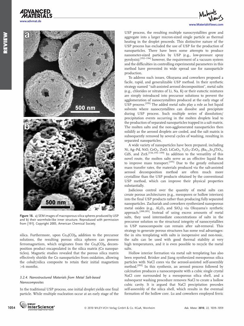
The polymer templating strategy has been further developed bySuslick and Suh who utilized an in situ generated polymertemplate for the preparation of macroporous silica spheres(Figure 18).[191] While the polymer templating method originallydeveloped by the Okuyama research group is robust and simple, itrelies on the use of expensive polymer beads for the creation ofmacroporosity. In Suh’s method, however, the polymerization ofan organic monomer (i.e., styrene) in the nebulized dropletshaving silica nanoparticles takes place at the first heating zoneheld at a low temperature, creating a silica/polystyrenenanocomposite in situ. The nanocomposite is then carried intoa second, hotter temperature zone where the in situ generatedpolymer is pyrolyzed out, producing macroporous silica spheres.The morphology and surface area of the porous silica spheres arealso easily controllable by manipulating the ratios of styrene and
mbH & Co. KGaA, Weinheim 1053
REVIE
W
www.advmat.dewww.MaterialsViews.com
Figure 18. a) SEM images of macroporous silica spheres produced by USPand b) their wormhole-like inner structure. Reproduced with permissionfrom [191]. Copyright 2005, American Chemical Society.
1054
silica. Furthermore, upon Co2(CO)8 addition to the precursorsolutions, the resulting porous silica spheres can possessferromagnetism, which originates from the Co2(CO)8 decom-position product encapsulated in the silica matrix (Co nanopar-ticles). Magnetic studies revealed that the porous silica matrixeffectively shields the Co nanoparticles from oxidation, allowingthe cobalt/silica composite to retain their initial magnetism>6 months.
3.2.4. Nanostructured Materials from Metal Salt-based
Nanocomposites
In the traditional USP process, one initial droplet yields one finalparticle. While multiple nucleation occur at an early stage of the
� 2010 WILEY-VCH Verlag Gmb
USP process, the resulting multiple nanocrystallites grow andaggregate into a larger micron-sized single particle as thermalheating in the droplet proceeds. This distinctive nature of theUSP process has excluded the use of USP for the production ofnanoparticles. There have been some attempts to producenanometer-sized particles by USP (e.g., low-pressure spraypyrolysis);[192–194] however, the requirement of a vacuum systemand the difficulties in controlling experimental parameters in thismethod have prevented its wide spread use for nanoparticleproduction.
To address such issues, Okuyama and coworkers proposed afacile, rapid, and generalizable USP method. In their syntheticstrategy named ‘‘salt-assisted aerosol decomposition’’, metal salts(e.g., chlorides or nitrates of Li, Na, K) or their eutectic mixturesare simply introduced into precursor solutions to prevent theagglomeration of nanocrystallites produced at the early stage ofUSP process.[195] The added metal salts play a role as hot liquidsolvents where nanocrystallites can dissolve and precipitateduring USP process. Such multiple series of dissolution/precipitation events occurring in the molten droplets lead tothe production of separated nanoparticles trapped in a salt matrix.The molten salts and the non-agglomerated nanoparticles thensolidify as the aerosol droplets are cooled, and the salt matrix issubsequently removed by several cycles of washing, resulting inseparated nanoparticles.
A wide variety of nanoparticles have been prepared, includingNi, Ag–Pd, NiO, CeO2, ZnO, LiCoO2, Y2O3–ZrO2, (Ba1-xSrx)TiO3,CdS, and ZnS.[156,195–199] In addition to the versatility of thisnovel route, the molten salts serve as an effective liquid fluxto improve mass transport.[195] Due to the greatly enhancedmass transfer rates, the materials produced via the salt-assistedaerosol decomposition method are often much morecrystalline than the USP products obtained by the conventionalUSP method, which can improve their physical propertiessubstantially.
Judicious control over the quantity of metal salts cancreate porous architectures (e.g., mesopores or hollow interiors)into the final USP products rather than producing fully separatednanoparticles. Zachariah and coworkers synthesized nanoporousmetal oxides (e.g., Al2O3 and SiO2) via Okuyama’s syntheticapproach.[200,201] Instead of using excess amounts of metalsalts, they used intermediate concentrations of salts in theprecursor solution so the structural integrity of nanocrystallitesin USP nanocomposite can remain after salt-removal. Thisstrategy to generate porous structures has some real advantages:the in situ templating with salts is inexpensive and non-toxic,the salts can be used with good thermal stability at veryhigh temperatures, and it is even possible to recycle the metalsalts.
Hollow interior formation via metal salt templating has alsobeen reported. Brinker and Jiang synthesized mesoporous silicaparticles with NaCl cores via the aerosol-assisted self-assemblymethod.[202] In this synthesis, an aerosol process followed bycalcination produces a nanocomposite with a cubic single crystalNaCl core surrounded by a mesoporous silica shell, and asubsequent washing procedure removes NaCl to create a hollowcubic cavity. It is argued that NaCl precipitation precedesself-assembly of the silica shell, which results in the eventualformation of the hollow core. Lu and coworkers employed ferric
H & Co. KGaA, Weinheim Adv. Mater. 2010, 22, 1039–1059
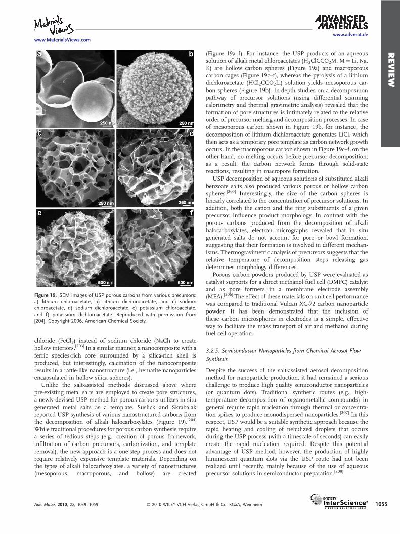
REVIE
W
www.MaterialsViews.comwww.advmat.de
Figure 19. SEM images of USP porous carbons from various precursors:a) lithium chloroacetate, b) lithium dichloroacetate, and c) sodiumchloroacetate, d) sodium dichloroacetate, e) potassium chloroacetate,and f) potassium dichloroacetate. Reproduced with permission from[204]. Copyright 2006, American Chemical Society.
chloride (FeCl3) instead of sodium chloride (NaCl) to createhollow interiors.[203] In a similar manner, a nanocomposite with aferric species-rich core surrounded by a silica-rich shell isproduced, but interestingly, calcination of the nanocompositeresults in a rattle-like nanostructure (i.e., hematite nanoparticlesencapsulated in hollow silica spheres).
Unlike the salt-assisted methods discussed above wherepre-existing metal salts are employed to create pore structures,a newly devised USP method for porous carbons utilizes in situgenerated metal salts as a template. Suslick and Skrabalakreported USP synthesis of various nanostructured carbons fromthe decomposition of alkali halocarboxylates (Figure 19).[204]
While traditional procedures for porous carbon synthesis requirea series of tedious steps (e.g., creation of porous framework,infiltration of carbon precursors, carbonization, and templateremoval), the new approach is a one-step process and does notrequire relatively expensive template materials. Depending onthe types of alkali halocarboxylates, a variety of nanostructures(mesoporous, macroporous, and hollow) are created
Adv. Mater. 2010, 22, 1039–1059 � 2010 WILEY-VCH Verlag G
(Figure 19a–f). For instance, the USP products of an aqueoussolution of alkali metal chloroacetates (H2ClCCO2M, M¼ Li, Na,K) are hollow carbon spheres (Figure 19a) and macroporouscarbon cages (Figure 19c–f), whereas the pyrolysis of a lithiumdichloroacetate (HCl2CCO2Li) solution yields mesoporous car-bon spheres (Figure 19b). In-depth studies on a decompositionpathway of precursor solutions (using differential scanningcalorimetry and thermal gravimetric analysis) revealed that theformation of pore structures is intimately related to the relativeorder of precursor melting and decomposition processes. In caseof mesoporous carbon shown in Figure 19b, for instance, thedecomposition of lithium dichloroacetate generates LiCl, whichthen acts as a temporary pore template as carbon network growthoccurs. In the macroporous carbon shown in Figure 19c–f, on theother hand, no melting occurs before precursor decomposition;as a result, the carbon network forms through solid-statereactions, resulting in macropore formation.
USP decomposition of aqueous solutions of substituted alkalibenzoate salts also produced various porous or hollow carbonspheres.[205] Interestingly, the size of the carbon spheres islinearly correlated to the concentration of precursor solutions. Inaddition, both the cation and the ring substituents of a givenprecursor influence product morphology. In contrast with theporous carbons produced from the decomposition of alkalihalocarboxylates, electron micrographs revealed that in situgenerated salts do not account for pore or bowl formation,suggesting that their formation is involved in different mechan-isms. Thermogravimetric analysis of precursors suggests that therelative temperature of decomposition steps releasing gasdetermines morphology differences.
Porous carbon powders produced by USP were evaluated ascatalyst supports for a direct methanol fuel cell (DMFC) catalystand as pore formers in a membrane electrode assembly(MEA).[206] The effect of these materials on unit cell performancewas compared to traditional Vulcan XC-72 carbon nanoparticlepowder. It has been demonstrated that the inclusion ofthese carbon microspheres in electrodes is a simple, effectiveway to facilitate the mass transport of air and methanol duringfuel cell operation.
3.2.5. Semiconductor Nanoparticles from Chemical Aerosol Flow
Synthesis
Despite the success of the salt-assisted aerosol decompositionmethod for nanoparticle production, it had remained a seriouschallenge to produce high quality semiconductor nanoparticles(or quantum dots). Traditional synthetic routes (e.g., high-temperature decomposition of organometallic compounds) ingeneral require rapid nucleation through thermal or concentra-tion spikes to produce monodispersed nanoparticles.[207] In thisrespect, USP would be a suitable synthetic approach because therapid heating and cooling of nebulized droplets that occursduring the USP process (with a timescale of seconds) can easilycreate the rapid nucleation required. Despite this potentialadvantage of USP method, however, the production of highlyluminescent quantum dots via the USP route had not beenrealized until recently, mainly because of the use of aqueousprecursor solutions in semiconductor preparation.[208]
mbH & Co. KGaA, Weinheim 1055
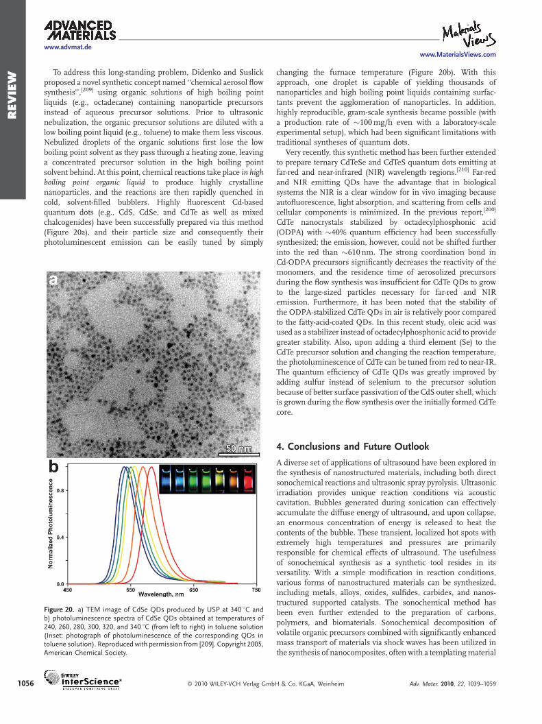
REVIE
W
www.advmat.dewww.MaterialsViews.com
1056
To address this long-standing problem, Didenko and Suslickproposed a novel synthetic concept named ‘‘chemical aerosol flowsynthesis’’,[209] using organic solutions of high boiling pointliquids (e.g., octadecane) containing nanoparticle precursorsinstead of aqueous precursor solutions. Prior to ultrasonicnebulization, the organic precursor solutions are diluted with alow boiling point liquid (e.g., toluene) to make them less viscous.Nebulized droplets of the organic solutions first lose the lowboiling point solvent as they pass through a heating zone, leavinga concentrated precursor solution in the high boiling pointsolvent behind. At this point, chemical reactions take place in highboiling point organic liquid to produce highly crystallinenanoparticles, and the reactions are then rapidly quenched incold, solvent-filled bubblers. Highly fluorescent Cd-basedquantum dots (e.g., CdS, CdSe, and CdTe as well as mixedchalcogenides) have been successfully prepared via this method(Figure 20a), and their particle size and consequently theirphotoluminescent emission can be easily tuned by simply
Figure 20. a) TEM image of CdSe QDs produced by USP at 340 8C andb) photoluminescence spectra of CdSe QDs obtained at temperatures of240, 260, 280, 300, 320, and 340 8C (from left to right) in toluene solution(Inset: photograph of photoluminescence of the corresponding QDs intoluene solution). Reproduced with permission from [209]. Copyright 2005,American Chemical Society.
� 2010 WILEY-VCH Verlag Gmb
changing the furnace temperature (Figure 20b). With thisapproach, one droplet is capable of yielding thousands ofnanoparticles and high boiling point liquids containing surfac-tants prevent the agglomeration of nanoparticles. In addition,highly reproducible, gram-scale synthesis became possible (witha production rate of �100mg/h even with a laboratory-scaleexperimental setup), which had been significant limitations withtraditional syntheses of quantum dots.
Very recently, this synthetic method has been further extendedto prepare ternary CdTeSe and CdTeS quantum dots emitting atfar-red and near-infrared (NIR) wavelength regions.[210] Far-redand NIR emitting QDs have the advantage that in biologicalsystems the NIR is a clear window for in vivo imaging becauseautofluorescence, light absorption, and scattering from cells andcellular components is minimized. In the previous report,[200]
CdTe nanocrystals stabilized by octadecylphosphonic acid(ODPA) with �40% quantum efficiency had been successfullysynthesized; the emission, however, could not be shifted furtherinto the red than �610 nm. The strong coordination bond inCd-ODPA precursors significantly decreases the reactivity of themonomers, and the residence time of aerosolized precursorsduring the flow synthesis was insufficient for CdTe QDs to growto the large-sized particles necessary for far-red and NIRemission. Furthermore, it has been noted that the stability ofthe ODPA-stabilized CdTe QDs in air is relatively poor comparedto the fatty-acid-coated QDs. In this recent study, oleic acid wasused as a stabilizer instead of octadecylphosphonic acid to providegreater stability. Also, upon adding a third element (Se) to theCdTe precursor solution and changing the reaction temperature,the photoluminescence of CdTe can be tuned from red to near-IR.The quantum efficiency of CdTe QDs was greatly improved byadding sulfur instead of selenium to the precursor solutionbecause of better surface passivation of the CdS outer shell, whichis grown during the flow synthesis over the initially formed CdTecore.
4. Conclusions and Future Outlook
A diverse set of applications of ultrasound have been explored inthe synthesis of nanostructured materials, including both directsonochemical reactions and ultrasonic spray pyrolysis. Ultrasonicirradiation provides unique reaction conditions via acousticcavitation. Bubbles generated during sonication can effectivelyaccumulate the diffuse energy of ultrasound, and upon collapse,an enormous concentration of energy is released to heat thecontents of the bubble. These transient, localized hot spots withextremely high temperatures and pressures are primarilyresponsible for chemical effects of ultrasound. The usefulnessof sonochemical synthesis as a synthetic tool resides in itsversatility. With a simple modification in reaction conditions,various forms of nanostructured materials can be synthesized,including metals, alloys, oxides, sulfides, carbides, and nanos-tructured supported catalysts. The sonochemical method hasbeen even further extended to the preparation of carbons,polymers, and biomaterials. Sonochemical decomposition ofvolatile organic precursors combined with significantly enhancedmass transport of materials via shock waves has been utilized inthe synthesis of nanocomposites, often with a templatingmaterial
H & Co. KGaA, Weinheim Adv. Mater. 2010, 22, 1039–1059
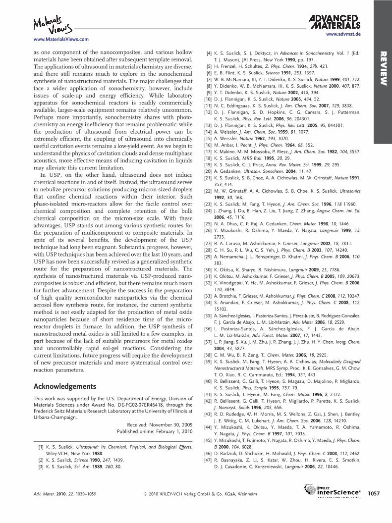
REVIE
W
www.MaterialsViews.comwww.advmat.de
as one component of the nanocomposites, and various hollowmaterials have been obtained after subsequent template removal.The applications of ultrasound inmaterials chemistry are diverse,and there still remains much to explore in the sonochemicalsynthesis of nanostructured materials. The major challenges thatface a wider application of sonochemistry, however, includeissues of scale-up and energy efficiency. While laboratoryapparatus for sonochemical reactors is readily commerciallyavailable, larger-scale equipment remains relatively uncommon.Perhaps more importantly, sonochemistry shares with photo-chemistry an energy inefficiency that remains problematic: whilethe production of ultrasound from electrical power can beextremely efficient, the coupling of ultrasound into chemicallyuseful cavitation events remains a low-yield event. As we begin tounderstand the physics of cavitation clouds and densemultiphaseacoustics, more effective means of inducing cavitation in liquidsmay alleviate this current limitation.
In USP, on the other hand, ultrasound does not inducechemical reactions in and of itself. Instead, the ultrasound servesto nebulize precursor solutions producing micron-sized dropletsthat confine chemical reactions within their interior. Suchphase-isolated micro-reactors allow for the facile control overchemical composition and complete retention of the bulkchemical composition on the micron-size scale. With theseadvantages, USP stands out among various synthetic routes forthe preparation of multicomponent or composite materials. Inspite of its several benefits, the development of the USPtechnique had long been stagnant. Substantial progress, however,with USP techniques has been achieved over the last 10 years, andUSP has now been successfully revived as a generalized syntheticroute for the preparation of nanostructured materials. Thesynthesis of nanostructured materials via USP-produced nano-composites is robust and efficient, but there remains much roomfor further advancement. Despite the success in the preparationof high quality semiconductor nanoparticles via the chemicalaerosol flow synthesis route, for instance, the current syntheticmethod is not easily adapted for the production of metal oxidenanoparticles because of short residence time of the micro-reactor droplets in furnace. In addition, the USP synthesis ofnanostructured metal oxides is still limited to a few examples, inpart because of the lack of suitable precursors for metal oxidesand uncontrollably rapid sol-gel reactions. Considering thecurrent limitations, future progress will require the developmentof new precursor materials and more systematical control overreaction parameters.
Acknowledgements
This work was supported by the U.S. Department of Energy, Division ofMaterials Sciences under Award No. DE-FG02-07ER46418, through theFrederick Seitz Materials Research Laboratory at the University of Illinois atUrbana-Champaign.
Received: November 30, 2009
Published online: February 1, 2010
[1] K. S. Suslick, Ultrasound: Its Chemical, Physical, and Biological Effects,
Wiley-VCH, New York 1988.
[2] K. S. Suslick, Science 1990, 247, 1439.
[3] K. S. Suslick, Sci. Am. 1989, 260, 80.
Adv. Mater. 2010, 22, 1039–1059 � 2010 WILEY-VCH Verlag G
[4] K. S. Suslick, S. J. Doktycz, in Advances in Sonochemistry, Vol. 1 (Ed.:
T. J. Mason), JAI Press, New York 1990, pp. 197.
[5] H. Frenzel, H. Schultes, Z. Phys. Chem. 1934, 27b. 421.
[6] E. B. Flint, K. S. Suslick, Science 1991, 253, 1397.
[7] W. B. McNamara, III, Y. T. Didenko, K. S. Suslick, Nature 1999, 401, 772.
[8] Y. Didenko, W. B. McNamara, III, K. S. Suslick, Nature 2000, 407, 877.
[9] Y. T. Didenko, K. S. Suslick, Nature 2002, 418, 394.
[10] D. J. Flannigan, K. S. Suslick, Nature 2005, 434, 52.
[11] N. C. Eddingsaas, K. S. Suslick, J. Am. Chem. Soc. 2007, 129, 3838.
[12] D. J. Flannigan, S. D. Hopkins, C. G. Camara, S. J. Putterman,
K. S. Suslick, Phys. Rev. Lett. 2006, 96, 204301.
[13] D. J. Flannigan, K. S. Suslick, Phys. Rev. Lett. 2005, 95, 044301.
[14] A. Weissler, J. Am. Chem. Soc. 1959, 81, 1077.
[15] A. Weissler, Nature 1962, 193, 1070.
[16] M. Anbar, I. Pecht, J. Phys. Chem. 1964, 68, 352.
[17] K. Makino, M. M. Mossoba, P. Riesz, J. Am. Chem. Soc. 1982, 104, 3537.
[18] K. S. Suslick, MRS Bull. 1995, 20, 29.
[19] K. S. Suslick, G. J. Price, Annu. Rev. Mater. Sci. 1999, 29, 295.
[20] A. Gedanken, Ultrason. Sonochem. 2004, 11, 47.
[21] K. S. Suslick, S. B. Choe, A. A. Cichowlas, M. W. Grinstaff, Nature 1991,
353, 414.
[22] M. W. Grinstaff, A. A. Cichowlas, S. B. Choe, K. S. Suslick, Ultrasonics
1992, 30, 168.
[23] K. S. Suslick, M. Fang, T. Hyeon, J. Am. Chem. Soc. 1996, 118 11960.
[24] J. Zhang, J. Du, B. Han, Z. Liu, T. Jiang, Z. Zhang, Angew. Chem. Int. Ed.
2006, 45, 1116.
[25] N. A. Dhas, C. P. Raj, A. Gedanken, Chem. Mater. 1998, 10, 1446.
[26] Y. Mizukoshi, R. Oshima, Y. Maeda, Y. Nagata, Langmuir 1999, 15,
2733.
[27] R. A. Caruso, M. Ashokkumar, F. Grieser, Langmuir 2002, 18, 7831.
[28] C. H. Su, P. L. Wu, C. S. Yeh, J. Phys. Chem. B 2003, 107, 14240.
[29] A. Nemamcha, J. L. Rehspringer, D. Khatmi, J. Phys. Chem. B 2006, 110,
383.
[30] K. Okitsu, K. Sharyo, R. Nishimura, Langmuir 2009, 25, 7786.
[31] K. Okitsu, M. Ashokkumar, F. Grieser, J. Phys. Chem. B 2005, 109, 20673.
[32] K. Vinodgopal, Y. He, M. Ashokkumar, F. Grieser, J. Phys. Chem. B 2006,
110, 3849.
[33] A. Brotchie, F. Grieser, M. Ashokkumar, J. Phys. Chem. C 2008, 112, 10247.
[34] S. Anandan, F. Grieser, M. Ashokkumar, J. Phys. Chem. C 2008, 112,
15102.
[35] A. Sanchez-Iglesias, I. Pastoriza-Santos, J. Perez-Juste, B. Rodrıguez-Gonzalez,
F. J. Garcıa de Abajo, L. M. Liz-Marzan, Adv. Mater. 2006, 18, 2529.
[36] I. Pastoriza-Santos, A. Sanchez-Iglesias, F. J. Garcıa de Abajo,
L. M. Liz-Marzan, Adv. Funct. Mater. 2007, 17, 1443.
[37] L. P. Jiang, S. Xu, J. M. Zhu, J. R. Zhang, J. J. Zhu, H. Y. Chen, Inorg. Chem.
2004, 43, 5877.
[38] C. M. Wu, B. P. Zeng, T., Chem. Mater. 2006, 18, 2925.
[39] K. S. Suslick, M. Fang, T. Hyeon, A. A. Cichowlas, Molecularly Designed
Nanostructured Materials, MRS Symp. Proc., K. E. Gonsalves, G. M. Chow,
T. O. Xiao, R. C. Cammarata, Ed.: 1994, 351, 443.
[40] R. Bellissent, G. Galli, T. Hyeon, S. Magazu, D. Majolino, P. Migliardo,
K. S. Suslick, Phys. Scripta 1995, T57. 79.
[41] K. S. Suslick, T. Hyeon, M. Fang, Chem. Mater. 1996, 8, 2172.
[42] R. Bellissent, G. Galli, T. Hyeon, P. Migliardo, P. Parette, K. S. Suslick,
J. Noncryst. Solids 1996, 205, 656.
[43] R. D. Rutledge, W. H. Morris, M. S. Wellons, Z. Gai, J. Shen, J. Bentley,
J. E. Wittig, C. M. Lukehart, J. Am. Chem. Soc. 2006, 128, 14210.
[44] Y. Mizukoshi, K. Okitsu, Y. Maeda, T. A. Yamamoto, R. Oshima,
Y. Nagata, J. Phys. Chem. B 1997, 101, 7033.
[45] Y. Mizukoshi, T. Fujimoto, Y. Nagata, R. Oshima, Y. Maeda, J. Phys. Chem.
B 2000, 104, 6028.
[46] D. Radziuk, D. Shchukin, H. Mohwald, J. Phys. Chem. C 2008, 112, 2462.
[47] R. Basnayake, Z. Li, S. Katar, W. Zhou, H. Rivera, E. S. Smotkin,
D. J. Casadonte, C. Korzeniewski, Langmuir 2006, 22, 10446.
mbH & Co. KGaA, Weinheim 1057
REVIE
W
www.advmat.dewww.MaterialsViews.com
1058
[48] B. Gates, B. Mayers, A. Grossman, Y. Xia, Adv. Mater. 2002, 14, 1749.
[49] B. T. Mayers, K. Liu, D. Sunderland, Y. Xia, Chem. Mater. 2003, 15, 3852.
[50] Y. Zhu, H. Li, Y. Koltypin, Y. R. Hacohen, A. Gedanken, Chem. Commun.
2001, 2616.
[51] R. V. Kumar, Y. Koltypin, X. N. Xu, Y. Yeshurun, A. Gedanken, I. Felner,
J. Appl. Phys. 2001, 89, 6324.
[52] P. Jeevanandam, Y. Koltypin, A. Gedanken, Nano Lett. 2001, 1, 263.
[53] S. Avivi, Y. Mastai, G. Hodes, A. Gedanken, J. Am. Chem. Soc. 1999, 121,
4196.
[54] S. Avivi, Y. Mastai, A. Gedanken, Chem. Mater. 2000, 12, 1229.
[55] K. V. P. M. Shafi, I. Felner, Y. Mastai, A. Gedanken, J. Phys. Chem. B 1999,
103, 3358.
[56] J. C. Yu, J. Yu, W. Ho, L. Zhang, Chem. Commun. 2001, 1942.
[57] D. Qian, J. Z. Jiang, P. L. Hansen, Chem. Commun. 2003, 1078.
[58] S.-H. Jung, E. Oh, K.-H. Lee, Y. Yang, C. G. Park, W. Park, S.-H. Jeong,
Cryst. Growth Des. 2008, 8, 265.
[59] H.-M. Xiong, D. G. Shchukin, H. Mohwald, Y. Xu, Y.-Y. Xia, Angew. Chem.
Int. Ed. 2009, 48, 2727.
[60] D. Zhang, H. Fu, L. Shi, C. Pan, Q. Li, Y. Chu, W. Yu, Inorg. Chem. 2007, 46,
2446.
[61] C. V. C. Krishnan, J. Burger, C. Chu, B., J. Phys. Chem. B 2006, 110, 20182.
[62] C.-J. Mao, H.-C. Pan, X.-C. Wu, J.-J. Zhu, H.-Y. Chen, J. Phys. Chem. B 2006,
110, 14709.
[63] D. P. Dutta, V. Sudarsan, P. Srinivasu, A. Vinu, A. K. Tyagi, J. Phys. Chem. C
2008, 112, 6781.
[64] M. Sivakumar, T. Takami, H. Ikuta, A. Towata, K. Yasui, T. Tuziuti,
T. Kozuka, D. Bhattacharya, Y. Iida, J. Phys. Chem. B 2006, 110, 15234.
[65] J. Geng, J. J. Zhu, H. Y. Chen, Cryst. Growth Des. 2006, 6, 321.
[66] J. Z. Geng, J.-J. Lu, D.-J. Chen, H.-Y., Inorg. Chem. 2006, 45, 8403.
[67] J. Geng, W. H. Hou, Y. N. Lv, J. J. Zhu, H. Y. Chen, Inorg. Chem. 2005, 44,
8503.
[68] D. P. Dutta, R. Ghildiyal, A. K. Tyagi, J. Phys. Chem. C 2009, 113, 16954.
[69] Y. Wang, X. Tang, L. Yin, W. Huang, Y. R. Hacohen, A. Gedanken, Adv.
Mater. 2000, 12, 1183.
[70] L. Zhang, J. C. Yu, Chem. Commun. 2003, 2078.
[71] J. C. Yu, L. Zhang, J. Yu, Chem. Mater. 2002, 14, 4647.
[72] J. C. Yu, L. Z. Zhang, J. Lin, J. Colloid Interface Sci. 2003, 260, 240.
[73] J. C. Yu, L. Zhang, Q. Li, K. W. Kwong, A. W. Xu, J. Lin, Langmuir 2003, 19,
7673.
[74] S.-H. Jung, E. Oh, K.-H. Lee, W. Park, S.-H. Jeong, Adv. Mater. 2007, 19,
749.
[75] J. Lai, K. V. P. M. Shafi, K. Loos, A. Ulman, Y. Lee, T. Vogt, C. Estournes,
J. Am. Chem. Soc. 2003, 125, 11470.
[76] T. Prozorov, B. McCarty, Z. Cai, R. Prozorov, K. S. Suslick, Appl. Phys. Lett.
2004, 85, 3513.
[77] H.-l. Li, Y.-c. Zhu, S.-g. Chen, O. Palchik, J.-p. Xiong, Y. Koltypin, Y. Gofer,
G.A., J. Solid State Chem. 2003, 172, 102.
[78] S. M. Zhou, Y. S. Feng, L. D. Zhang, Mater. Lett. 2003, 57, 2936.
[79] S. M. Zhou, Y. S. Feng, L. D. Zhang, J. Mater. Res. 2003, 18, 1188.
[80] M. M. Mdleleni, T. Hyeon, K. S. Suslick, J. Am. Chem. Soc. 1998, 120,
6189.
[81] I. Uzcanga, I. Bezverkhyy, P. Afanasiev, C. Scott, M. Vrinat, Chem. Mater.
2005, 17, 3575.
[82] H. Wang, J. J. Zhu, J. M. Zhu, H. Y. Chen, J. Phys. Chem. B 2002, 106, 3848.
[83] J. Zhu, Y. Koltypin, A. Gedanken, Chem. Mater. 2000, 12, 73.
[84] J. J. Zhu, H. Wang, S. Xu, H. Y. Chen, Langmuir 2002, 18, 3306.
[85] X. Qiu, C. Burda, R. Fu, L. Pu, H. Chen, J. Zhu, J. Am. Chem. Soc. 2004,
126, 16276.
[86] Y. Xie, X. Zheng, X. Jiang, J. Lu, L. Zhu, Inorg. Chem. 2002, 41, 387.
[87] B. Li, Y. Xie, J. Huang, Y. Liu, Y. Qian, Chem. Mater. 2000, 12, 2614.
[88] H. L. Li, Y. C. Zhu, O. Palchik, Y. Koltypin, A. Gedanken, V. Palchik,
M. Slifkin, A. Weiss, Inorg. Chem. 2002, 41, 637.
[89] B. Pejova, I. Grozdanov, D. Nesheva, A. Petrova, Chem. Mater. 2008, 20,
2551.
� 2010 WILEY-VCH Verlag Gmb
[90] B. C. Gates, in Catalytic Chemistry, Wiley & Sons, New York 1992, pp. 406.
[91] T. A. Pecoraro, R. R. Chianelli, J. Catal. 1981, 67, 430.
[92] M. J. Ledoux, O. Michaux, G. Agostini, P. Panisscd, J. Catal. 1986, 102,
275.
[93] J. J. Zhu, S. Xu, H. Wang, J. M. Zhu, H.-Y. Chen, Adv. Mater. 2003, 15,
156.
[94] J. Geng, B. Liu, L. Xu, F. N. Hu, J. J. Zhu, Langmuir 2007, 23, 10286.
[95] S. F. Wang, F. Gu, M. K. Lu, Langmuir 2006, 22, 398.
[96] H. Zhou, T. Fan, D. Zhang, Q. Guo, H. Ogawa, Chem. Mater. 2007, 19,
2144.
[97] M. J. Murcia, D. L. Shaw, H. Woodruff, C. A. Naumann, B. A. Young,
E. C. Long, Chem. Mater. 2006, 18, 2219.
[98] T. Hyeon, M. Fang, K. S. Suslick, J. Am. Chem. Soc. 1996, 118, 5492.
[99] J. D. Oxley, M. M. Mdleleni, K. S. Suslick, Catal. Today 2004, 88, 139.
[100] K. S. Suslick, D. J. Casadonte, J. Am. Chem. Soc. 1987, 109, 3459.
[101] K. S. Suslick, S. J. Doktycz, J. Am. Chem. Soc. 1989, 111, 2342.
[102] K. S. Suslick, S. J. Doktycz, Chem. Mater. 1989, 1, 6.
[103] S. J. Doktycz, K. S. Suslick, Science. 1990, 247, 1067.
[104] T. Prozorov, R. Prozorov, K. S. Suslick, J. Am. Chem. Soc. 2004, 126, 13890.
[105] V. G. Pol, A. Gedanken, J. Calderon-Moreno, Chem. Mater. 2003, 15, 1111.
[106] V. G. Pol, M. Motiei, A. Gedanken, J. Calderon-Moreno, Y. Mastai, Chem.
Mater. 2003, 15, 1378.
[107] V. G. Pol, H. Grisaru, A. Gedanken, Langmuir 2005, 21, 3635.
[108] A.-L. Morel, S. I. Nikitenko, K. Gionnet, A. Wattiaux, J. Lai-Kee-Him,
C. Labrugere, B. Chevalier, G. Deleris, C. Petibois, A. Brisson,
M. Simonoff, ACS Nano. 2008, 2, 847.
[109] K. V. P. M. Shafi, A. Ulman, X. Yan, N. L. Yang, M. Himmelhaus,
M. Grunze, Langmuir 2001, 17, 1726.
[110] K. V. P. M. Shafi, A. Ulman, A. Dyal, X. Yan, N. L. Yang, C. Estournes,
L. Fournes, A. Wattiaux, H. White, M. Rafailovich, Chem. Mater. 2002, 14,
1778.
[111] Q. Chen, C. Boothroyd, G. H. Tan, N. Sutanto, A. M. Soutar, Z. T. Zeng,
Langmuir 2008, 24, 650.
[112] T. Gao, T. Wang, Chem. Commun. 2004, 2558.
[113] T. Gao, Q. Li, T. Wang, Chem. Mater. 2005, 17, 887.
[114] J.-E. Park, M. Saikawa, M. Atobe, T. Fuchigami, Chem. Commun. 2006,
2708.
[115] G. Dantsin, K. S. Suslick, J. Am. Chem. Soc. 2000, 122, 5214.
[116] J. E. Jones, M. C. Cheshire, D. J. Casadonte, C. C. Phifer,Org. Lett. 2004, 6,
1915.
[117] J. Walter, M. Nishioka, S. Hara, Chem. Mater. 2001, 13, 1828.
[118] N. A. Dhas, K. S. Suslick, J. Am. Chem. Soc. 2005, 127, 2368.
[119] J. H. Bang, K. S. Suslick, J. Am. Chem. Soc. 2007, 129, 2242.
[120] N. Du, H. Zhang, B. D. Chen, J. B. Wu, X. Y. Ma, Z. H. Liu, Y. Q. Zhang,
D. R. Yang, X. H. Huang, J. P. Tu, Adv. Mater. 2007, 19, 4505.
[121] J. Wang, K. P. Loh, Y. L. Zhong, M. Lin, J. Ding, Y. L. Foo, Chem. Mater.
2007, 19, 2566.
[122] J. Yin, X. Qian, J. Yin, M. Shi, G. Zhou, Mater. Lett. 2003, 57, 3859.
[123] X. H. Sun, C. P. Li, N. B. Wong, C. S. Lee, S. T. Lee, B. K. Teo, J. Am. Chem.
Soc. 2002, 124, 14856.
[124] C. P. Li, B. K. Teo, X. H. Sun, N. B. Wong, S. T. Lee, Chem. Mater. 2005, 17,
5780.
[125] S. H. Jeong, J. H. Ko, J. B. Park, W. Park, J. Am. Chem. Soc. 2004, 126,
15982.
[126] L. M. Viculis, J. J. Mack, R. B. Kaner, Science. 2003, 299, 1361.
[127] K. S. Suslick, M. W. Grinstaff, J. Am. Chem. Soc. 1990, 112, 7807.
[128] M. W. Grinstaff, K. S. Suslick, Proc. Natl. Acad. Sci. U. S. A. 1991, 88,
7708.
[129] K. J. Liu, M. W. Grinstaff, J. Jiang, K. S. Suslick, H. M. Swartz, W. Wang,
Biophys. J. 1994, 67, 896.
[130] K. S. Suslick, M. W. Grinstaff, K. J. Kolbeck, M. Wong,Ultrason. Sonochem.
1994, 1, S65.
[131] A. G.Webb,M.Wong, K. J. Kolbeck, R. L. Magin, L. J. Wilmes, K. S. Suslick,
J. Magn. Reson. Imaging 1996, 6, 675.
H & Co. KGaA, Weinheim Adv. Mater. 2010, 22, 1039–1059
REVIE
W
www.MaterialsViews.comwww.advmat.de
[132] J. J. Eckburg, J. C. Chato, K. J. Liu, M. W. Grinstaff, H. M. Swartz,
K. S. Suslick, F. P. Auteri, J. Biomech. Eng. 1996, 118, 193.
[133] F. J.-J. Toublan, S. Boppart, K. S. Suslick, J. Am. Chem. Soc. 2006, 128,
3472.
[134] E. M. Dibbern, F. J.-J. Toublan, K. S. Suslick, J. Am. Chem. Soc. 2006, 128,
6540.
[135] S. Biggs, F. Grieser, Macromolecules. 1995, 28, 4877.
[136] M. Bradley, M. Ashokkumar, F. Grieser, J. Am. Chem. Soc. 2003, 125, 525.
[137] H. K. Kim, K. Matyjaszewski, J. Am. Chem. Soc. 1988, 110, 3321.
[138] T. T. Kodas, M. Hampden-Smith, Aerosol Processing of Materials,
Wiley-VCH, New York 1999.
[139] K. Okuyama, W. Lenggoro, Chem. Eng. Sci. 2003, 58, 537.
[140] G. L. Messing, S.-C. Zhang, G. V. Jayanthi, J. Am. Ceram. Soc. 1993, 76,
2707.
[141] R. W. Wood, A. L. Loomis, Phil. Mag. 1927, 7, 417.
[142] R. J. Lang, J. Acoustical Soc. 1962, 34, 6.
[143] I. W. Lenggoro, T. Hata, F. Iskandar, M. M. Lunden, O.K., J. Mater. Res.
2000, 15, 733.
[144] P. S. Patil, Mater. Chem. Phys. 1999, 59, 185.
[145] T. C. Pluym, Q. H. Powell, G.A.S., T. L. Ward, T. T. Kodas, L.-M. Wang,
H. D. Glicksman, J. Aerosol Sci. 1993, 24, 383.
[146] T. C. Pluym, S. W. Lyons, Q. H. Powell, A. S. Gurav, T. T. Kodas,
L.-M. Wang, H. D. Glicksman, Mater. Res. Bull. 1993, 28, 369.
[147] D. Majumdar, T. T. Kodas, H. D. Glicksman, Adv. Mater. 1996, 8, 1020.
[148] J. H. Kim, T. A. Germer, G.W.Mulholland, S. H. Ehrman, Adv.Mater. 2002,
14, 518.
[149] K. Nagashima, M. Wada, A. Kato, J. Mater. Res. 1990, 5, 2828.
[150] S. Gurmen, S. Stopic, B. Friedrich, Mater. Res. Bull. 2006, 41, 1882.
[151] T. C. Pluym, T. T. Kodas, L.-M. Wang, H. D. Glicksman, J. Mater. Res. 1995,
10, 1661.
[152] J. H. Kim, V. I. Babushok, T. A. Germer, G. W. Mulholland, S. H. Ehrman,
J. Mater. Res. 2003, 18, 1614.
[153] S. R. C. Vivekchand, G. Gundiah, A. Govindaraj, C. N. R. Rao, Adv. Mater.
2004, 16, 1842.
[154] Y. C. Kang, H. S. Roh, S. B. Park, Adv. Mater. 2000, 12, 451.
[155] B. Xia, I. W. Lenggoro, K. Okuyama, Chem. Mater. 2002, 14, 4969.
[156] I. W. Lenggoro, Y. Itoh, K. Okuyama, T. O. Kim, J. Mater. Res. 2004, 19,
3534.
[157] I. W. Lenggoro, C. Panatarani, K. Okuyama, Mater. Sci. Eng. B 2004, 113,
60.
[158] K. Y. Jung, H. W. Lee, Y. C. Kang, S. B. Park, Y. S. Yang, Chem. Mater. 2005,
17, 2729.
[159] S.-H. Park, S. W. Oh, Y.-K. Sun, J. Power Sources 2005, 146, 622.
[160] Y. Huang, Z. Zheng, Z. Ai, L. Zhang, X. Fan, Z. Zou, J. Phys. Chem. B 2006,
110, 19323.
[161] C. R. Michel, E. R. Lopex, H. R. Zea, Mater. Res. Bull. 2006, 41, 209.
[162] D. Jugovic, N. Cvjeticanin, V. Kusigerski, M. Mitric, M. Miljkovic,
D. Makovec, D. Uskokovic, Mater. Res. Bull. 2007, 42, 515.
[163] T.-H. Teng, M.-R. Yang, S.-h. Wu, Y.-P. Chiang, Solid State Commun. 2007,
142, 389.
[164] W.-N. Wang, W. Widiyastuti, I. W. Lenggoro, T. O. Kim, K. Okuyama,
J. Electrochem. Soc. 2007, 154, J121.
[165] C.-L. Chang, C.-S. Hsu, B.-H. Hwang, J. Power Sources 2008, 179, 734.
[166] R. R. Chamberlin, J. S. Skarman, J. Electrochem. Soc. 1966, 113, 86.
[167] M. E. Davis, Nature 2002, 417, 813.
[168] G. J. d, A. Soler-Illia, C. Sanchez, B. Lebeau, J. Patarin, Chem. Rev. 2002,
102, 4093.
[169] S. W. Boettcher, J. Fan, C.-K. Tsung, Q. Shi, G. D. Stucky, Acc. Chem. Res.
2007, 40, 784.
Adv. Mater. 2010, 22, 1039–1059 � 2010 WILEY-VCH Verlag G
[170] M. G. Kanatzidis, Adv. Mater. 2007, 19, 1165.
[171] C. J. Brinker, Y. Lu, A. Sellinger, H. Fan, Adv. Mater. 1999, 11, 579.
[172] Y. Lu, H. Fan, A. Stump, T. L. Ward, T. Rieker, C. J. Brinker, Nature 1999,
398, 223.
[173] X. Ji, Q. Hu, J. E. Hampsey, X. Qiu, L. Gao, J. He, Y. Lu, Chem. Mater. 2006,
18, 2265.
[174] H. Fan, F. Van Swol, Y. Lu, C. J. Brinker, J. Non-Crystalline Solids 2001, 285,
71.
[175] Y. Lu, B. F. McCaughey, D. Wang, J. E. Hampsey, N. Doke, Z. Yang,
C. J. Brinker, Adv. Mater. 2003, 15, 1733.
[176] J. E. Hampsey, S. Arsenault, Q. Hu, Y. Lu, Chem. Mater. 2005, 17, 2475.
[177] X. Ji, J. E. Hampsey, Q. Hu, J. He, Z. Yang, Y. Lu, Chem. Mater. 2003, 15,
3656.
[178] J. H. Bang, S. H. Lim, E. Park, K. S. Suslick, Langmuir 2008, 24, 13168.
[179] L. Li, C.-K. Tsung, T. Ming, Z. Sun, W. Ni, Q. Shi, G. D. Stucky, J. Wang,
Adv. Funct. Mater. 2008, 18, 2956.
[180] T. Zheng, J. Zhan, J. Pang, G. S. Tan, J. He, G. L. McPherson, Y. Lu,
V. T. John, Adv. Mater. 2006, 18, 2735.
[181] C. Boissiere, L. Nicole, C. Gervais, F. Babonneau, M. Antonietti,
H. Amenitsch, C. Sanchez, D. Grosso, Chem. Mater. 2006, 18, 5238.
[182] L. Li, C.-K. Tsung, Z. Yang, G. D. Stucky, L. D. Sun, J. F. Wang, C. H. Yan,
Adv. Mater. 2008, 20, 903.
[183] S. E. Skrabalak, K. S. Suslick, J. Am. Chem. Soc. 2005, 127, 9990.
[184] J. H. Bang, R. J. Helmich, K. S. Suslick, Adv. Mater. 2008, 20, 2599.
[185] W. H. Suh, A. R. Jang, Y.-H. Suh, K. S. Suslick, Adv. Mater. 2006, 18, 1832.
[186] J. E. Hampsey, Q. Hu, L. Rice, J. Pang, Z. Wu, Y. Lu, Chem. Commun. 2005,
3606.
[187] Q. Hu, Y. Lu, G. P. Meisner, J. Phys. Chem. C 2008, 112, 1516.
[188] F. Iskandar, A. Mikrajuddin, K. Okuyama, Nano Lett. 2001, 1, 231.
[189] F. Iskandar, A. Mikrajuddin, K. Okuyama, Nano Lett. 2002, 2, 389.
[190] F. Iskandar, A. B. D. Nandiyanto, K. M. Yun, H.J.C.J., K. Okuyama,
P. Biswas, Adv. Mater. 2007, 19, 1408.
[191] W. H. Suh, K. S. Suslick, J. Am. Chem. Soc. 2005, 127, 12007.
[192] Y. C. Kang, S. B. Park, J. Aerosol Sci. 1995, 26, 1131.
[193] I. W. Lenggoro, Y. Itoh, N. Iida, K. Okuyama, Mater. Res. Bull. 2003, 38,
1819.
[194] W.-N. Wang, I. W. Lenggoro, Y. Terashi, Y.-C. Wang, K. Okuyama, J. Mater.
Res. 2005, 20, 2873.
[195] B. Xia, W. Lenggoro, K. Okuyama, Adv. Mater. 2001, 13, 1579.
[196] B. Xia, I. W. Lenggoro, K. Okuyama, J. Mater. Chem. 2001, 11, 2925.
[197] Y. Itoh, I. W. Lenggoro, K. Okuyama, L. Madler, S. E. Pratsinis, J. Nanopart.
Res. 2003, 5, 191.
[198] C. Panatarani, I. W. Lenggoro, K. Okuyama, J. Nanopart. Res. 2003, 5, 47.
[199] Y. Itoh, M. Abdullah, K. Okuyama, J. Mater. Res. 2004, 19, 1077.
[200] S. H. Kim, B. Y. H. Liu, M. R. Zachariah, Chem. Mater. 2002, 14, 2889.
[201] S. H. Kim, B. Y. H. Liu, M. R. Zachariah, Langmuir 2004, 20, 2523.
[202] X. Jiang, C. J. Brinker, J. Am. Chem. Soc. 2006, 128, 4512.
[203] T. Zheng, J. Pang, G. Tan, J. He, G. L. McPherson, Y. Lu, V. T. John, J. Zhan,
Langmuir 2007, 23, 5143.
[204] S. E. Skrabalak, K. S. Suslick, J. Am. Chem. Soc. 2006, 128, 12642.
[205] S. E. Skrabalak, K. S. Suslick, J. Phys. Chem. C 2007, 111, 17807.
[206] J. H. Bang, K. Han, S. E. Skrabalak, H. Kim, K. S. Suslick, J. Phys. Chem. C
2007, 111, 10959.
[207] C. B. Murray, C. R. Kagan, M. G. Bawendi, Annu. Rev. Mater. Sci. 2000, 30,
545.
[208] K. Okuyama, I. W. Lenggoro, N. Tagami, S. Tamaki, N. Tohge, J. Mater.
Sci. 1997, 32, 1229.
[209] Y. T. Didenko, K. S. Suslick, J. Am. Chem. Soc. 2005, 127, 12196.
[210] J. H. Bang, W. H. Suh, K. S. Suslick, Chem. Mater. 2008, 20, 4033.
mbH & Co. KGaA, Weinheim 1059