Embed Size (px)
Citation preview
APPLICATIONS OF PARTICLE ACCELERATORS
IN EUROPE
TAB
LE
OF
CO
NTE
NTS
AP
PLI
CA
TIO
NS
OF
PA
RT
ICLE
AC
CE
LER
ATO
RS
IN E
UR
OP
E 1. FOREWORD1.1. Applications of Particle Accelerators in Europe (APAE) 1.2. Organising committee
2. INTRODUCTION 2.1. What is a particle accelerator?
2.1.1. The units used
2.2. How do particle accelerators work?
2.2.1. Electrostatic acceleration
2.2.2. Radiofrequency acceleration
2.2.3. Components of a modern accelerator layout
2.3. Types of accelerator
2.3.1. Linacs
2.3.2. Circular accelerators
2.4. What can the accelerated particles do?
2.5. The everyday applications of particle accelerators
2.6. Developments in accelerator technology
2.6.1. Use of superconducting components
2.6.2. New compact accelerator configurations
3. ACCELERATORS AND HEALTH 3.1. Introduction
3.2. Radiotherapy
3.2.1. State of the art
3.2.2. X-ray therapy
3.2.3. Particle therapy
3.2.4. Research challenges
3.2.5. Generic challenges
3.2.6. Priority areas for R&D in radiotherapy
3.2.7. Impact on industry and education
3.3. Radionuclides
3.3.1. State of the art
3.3.2. Radionuclide production
3.3.3. Research challenges
3.3.4. Political and social challenges
3.3.5. Priority areas for R&D in medical radionuclide production
3.3.6. Impact on industry and education
3.4. Key recommendations in funding for applications of particle accelerators to health
68
16
2
TAB
LE
OF
CO
NTE
NTS
AP
PLIC
AT
ION
S OF
PAR
TIC
LE A
CC
ELE
RA
TOR
S IN E
UR
OP
E
4. ACCELERATORS AND INDUSTRY 4.I. Introduction
4.2. Very low-energy e-beams
4.2.1. Background and state of the art
4.2.2. Applications of very low-energy e-beams
4.2.3. Research challenges
4.2.4. Other challenges
4.2.5. Priority areas for R&D
4.2.6. Impact on industry and education
4.3. Low-energy e-beams
4.3.1. Background and state of the art
4.3.2. Applications of low-energy e-beams
4.3.3. Research challenges
4.3.4. Other challenges
4.3.5. Priority areas for R&D
4.3.6. Impact on industry and education
4.4. Ion beams
4.4.1. Ion beam analysis – state of the art
4.4.2. Applications of ion beams for the environment and cultural heritage
4.4.3. Research challenges
4.4.4. Priority areas for R&D
4.4.5. Ion implantation
4.4.6. Applications of ion implantation
4.4.7. Priority areas for R&D
4.4.8. Impact on industry and education/skills transfer
4.5. Key recommendations for applications of accelerators to industry
5. ACCELERATORS AND ENERGY 5.1. Introduction
5.2. Solving nuclear fission problems
5.2.1. Current status
5.2.2. Destroying long-lived radioactive waste
5.2.3. Accelerator-driven transmutation
5.2.4. Accelerator-driven nuclear power generation
5.3. Paving the road towards fusion-based nuclear energy
5.3.1. Current status
5.3.2. Accelerators for intense sources of neutrons
5.4. Research challenges
5.4.1. Nuclear fission
5.4.2. Nuclear fusion
5.4.3. Other challenges – licensing aspects
5.5. Priority areas for R&D
5.6. Impact in industry and education
5.7. Key recommendations for applications of particle accelerators to energy
42
70
3

TAB
LE
OF
CO
NTE
NTS
6. ACCELERATORS AND SECURITY6.1. Introduction
6.2. Border security
6.2.1. Current status
6.2.2. X-ray imaging
6.2.3. Use of neutrons
6.2.4. Gamma-rays
6.3. Counter-terrorism
6.4. Nuclear security
6.4.1. Support to maintaining international treaties, safeguards and nuclear arms control
6.4.2. Support to stockpile stewardship
6.5. Research challenges
6.5.1. Border security
6.5.2. Nuclear security
6.6. Other challenges
6.7. Priority areas for R&D in security
6.8. Impact on industry and education
6.8.1. Industry
6.8.2. Education
6.9. Key recommendations for applications of particle accelerators to security
80
4
AP
PLI
CA
TIO
NS
OF
PA
RT
ICLE
AC
CE
LER
ATO
RS
IN E
UR
OP
E
7. ACCELERATORS AND PHOTON SOURCES7.1. Introduction
7.1.1. Current use of photon sources in research
7.2. State of the art
7.2.1. Synchrotron-based light sources
7.2.2. Linac-based light sources
7.2.3. Compton sources
7.2.4. Advantages and disadvantages of the di�erent light sources
7.3. Research challenges
7.3.1. SRs
7.3.2. SASE FELs
7.3.3. ERLs
7.4. Other challenges
7.5. Priority areas for R&D
7.5.1. Compact FELs using plasma-wave accelerators
7.5.2. Accelerator on a chip
7.6. Impact on industry and education
7.6.1. Industry
7.6.2. Education
7.7. Key recommendations for applications of particle accelerators to photon sources
8. ACCELERATORS AND NEUTRON SOURCES8.1. Introduction
8.1.2. Applications of neutron scattering
8.2. State of the art
8.2.1. Neutrons from research reactors
8.2.2. Neutrons from particle accelerators
8.3. Current usage of neutron sources
8.4. Compact neutron sources (CNSs)
8.5. Research challenges
8.6. Other challenges
8.7. Priority areas for R&D
8.8. Impact on industry and education
8.9. Key recommendations for applications of particle accelerators to neutron sources
9. A SUMMARY OF KEY RECOMMENDATIONS FOR APPLICATIONS OF PARTICLE ACCELERATORS
TAB
LE
OF
CO
NTE
NTS
112
102
88
5
AP
PLIC
AT
ION
S OF
PAR
TIC
LE A
CC
ELE
RA
TOR
S IN E
UR
OP
E
PARTICLE ACCELERATORS ARE SOPHISTICATED MACHINES, WHICH, IN PROVIDING ENERGY TO SUBATOMIC PARTICLES, MAKE THEM CAPABLE OF INTERACTING WITH ATOMIC NUCLEI, OF GENERATING NEW PARTICLES, OF PRODUCING INTENSE STREAMS OF X-RAYS OR NEUTRONS, AND OF PRECISELY DELIVERING THEIR ENERGY TO MATERIALS OR BIOLOGICAL CELLS.
In less than the 90 years since their invention, accelerators have propelled modern science – contributing to more than one-third of the Nobel prizes in physics – and they have reached well beyond fundamental research towards applied science and market applications. Although the most visible accelerators are the large machines employed in particle physics, of the more than 30,000 accelerators that currently exist in the world, only less than 1 per cent operate for the benefit of fundamental research; the large majority are small accelerators used for healthcare or in industry.
The transition of accelerator technology, from its use in basic science to applications more directly benefiting society, has been a very visible trend in recent decades; and that represents only the first step in a major evolution for particle accelerators. While accelerators for basic research are growing in dimensions and complexity, the increasing expansion and accessibility of accelerator technologies, together with the emergence of smaller, compact designs, are fostering their spread across a wealth of applications in fields as diverse as health, industry, energy, security, and the environment. All these accelerator applications share a common drive to move beyond the traditional chemical approaches used in analysis and material transformations to those that rely on interactions at the atomic and subatomic scale, thus opening up new opportunities in terms of novel products, industrial processes, and techniques addressing societal problems. These include improving cancer treatment and medical diagnostics, reducing air pollution and treating radioactive waste.
1. FOREWORD1.
FO
RE
WO
RD
1.1. APPLICATIONS OF PARTICLE ACCELERATORS IN EUROPE (APAE)Applications of Particle Accelerators in Europe (APAE) is an EU project, launched in June 2015, which aims to show how the accelerator technology, developed as a result of accelerator research, is of benefit to the wider community. It is organised by Work Package 4 of the EuCARD2 project, an Integrating Activity Project for coordinated Research and Development on Particle Accelerators, co-funded by the European Commission under the FP7 Capacities.
The APAE project aims to promote the development of novel accelerator technologies and to identify new applications in six sectors:
› Health – accelerators produce particles and radiation for radiotherapy, and make radionuclides for clinical applications.
› Industry – accelerators generate electron beams and ion beams for materials analysis and modification.
› Energy – accelerators can be employed in the transmutation of nuclear waste and in nuclear fusion.
› Security – accelerators generate X-rays, gamma-rays and neutrons required for screening operations in border security, counter-terrorism and nuclear security.
› Analysis with photons – the accelerator-based production of very bright electromagnetic radiation (mostly X-rays) for studies of the structure and behaviour of a wide variety of materials at the atomic and molecular scales using a variety of X-ray analytical techniques such as crystallography. The main photon sources used are synchrotrons and free electron lasers.
› Analysis with neutrons – the accelerator-based production of neutron beams via spallation for studies of the structure and behaviour of materials at the atomic and molecular scales using neutron-scattering techniques.
This document explains the current state of the art in accelerator technology and how accelerators are used in these applied areas. It also identifies the key future developments that would be beneficial to these sectors. 6
AP
PLI
CA
TIO
NS
OF
PA
RT
ICLE
AC
CE
LER
ATO
RS
IN E
UR
OP
E
EUROPE’S ROLEEurope hosts a large infrastructure of accelerator laboratories dedicated to applied research or medical treatments, a wide network of advanced universities and research centres active in the accelerator field, as well as established companies and innovative SMEs producing accelerator components and complete small-scale accelerators. This dynamic environment makes Europe a world-leader in developing and exploiting accelerator technology to the advantage of society. The ambition of the European Commission and the main European national agencies is to maintain this leading position, with the goal of improving the quality of life of European citizens, while generating employment and economic growth.
To achieve these results, much remains to be done on the technological side, as well as exploring further the benefits of accelerators in many everyday applications. On the societal side, we need to increase the awareness of the potential of accelerator technology amongst decision-makers and the general public, and we need to improve our schemes for public–private partnerships and for sharing the financial risks inherent with new technologies. We also need to raise public acceptance of technologies in relation to perceptions about radioactivity, proving that radiation risks are well understood and mastered in modern accelerator technology.
With these objectives in mind, the EuCARD-2 (European Coordinated Accelerator Research and Development) Integrating Activity is proud to promote the preparation of this comprehensive document on the applications
of accelerators. EuCARD-2 is supported by the European Commission under the FP7 programme to foster and develop particle-accelerator technologies; promoting accelerator applications is a priority for our project and for the entire particle-accelerator community .
Maurizio Vretenar, EuCARD-2 Coordinator (CERN)
1. FOR
EW
OR
D
1.2. ORGANISING COMMITTEEAngeles Faus-Golfe (IFIC Valencia – LAL Orsay), APAE coordinator
Rob Edgecock (U. Huddersfield – STFC)
Roy Aleksan (CEA),
Oliver Boine-Frankenheim (GSI Darmstadt – TUD)
Phil Burrows (JAI Oxford – UOX)
Giovanni Annelli (CERN)
Andrea Pisent (INFN LNL)
Agnes Szeberenyi (CERN)
Jennifer Toes (CERN)
7
AP
PLIC
AT
ION
S OF
PAR
TIC
LE A
CC
ELE
RA
TOR
S IN E
UR
OP
E
DURING THE PAST CENTURY, PARTICLE ACCELERATORS AND THEIR TECHNOLOGY HAVE PLAYED AN ESSENTIAL ROLE IN DELIVERING THE SCIENTIFIC ADVANCES THAT HAVE LED TO IMPROVED STANDARDS OF LIVING AND WELLBEING. TODAY, ACCELERATORS IN VARIOUS CONFIGURATIONS ARE BEING INCREASINGLY APPLIED AS TOOLS NOT ONLY IN THE LABORATORY BUT ALSO IN HOSPITALS AND INDUSTRY. AS ACCELERATOR TECHNOLOGY DEVELOPS, THE POTENTIAL FOR NEW APPLICATIONS IS EXPANDING, WITH EUROPE IN A STRONG POSITION TO EXPLOIT THEM.
Rob Edgecock
While originally invented and developed for basic scientific research, particle accelerators now play a vital role in improving health and prosperity in Europe, and around the world. They are used for applications ranging from treating cancer, through making better electronics, to removing harmful micro-organisms from food and water. There are approaching 40,000 accelerators in use globally, and it is estimated that their application underpins nearly half a trillion dollars-worth of commerce a year.* Despite their importance, most people do not even know of their existence, beyond perhaps the Large Hadron Collider (LHC) at CERN, a massive machine employed to probe the fundamental nature of matter and the Universe. Only a few patients receiving radiotherapy, for example, will know that the technology being used to treat them has similarities to that of the LHC.
The aim of this document is to explain the significant role of accelerators in practical areas such as medical treatments, manufacturing, energy generation, the detection of materials and analysis, and show how the continued development of particle accelerators is essential to further improve social and economic development in Europe. It will explain what particle accelerators are, show what they are used for, and describe how the current applications could be improved and new applications created by research on accelerator technology.
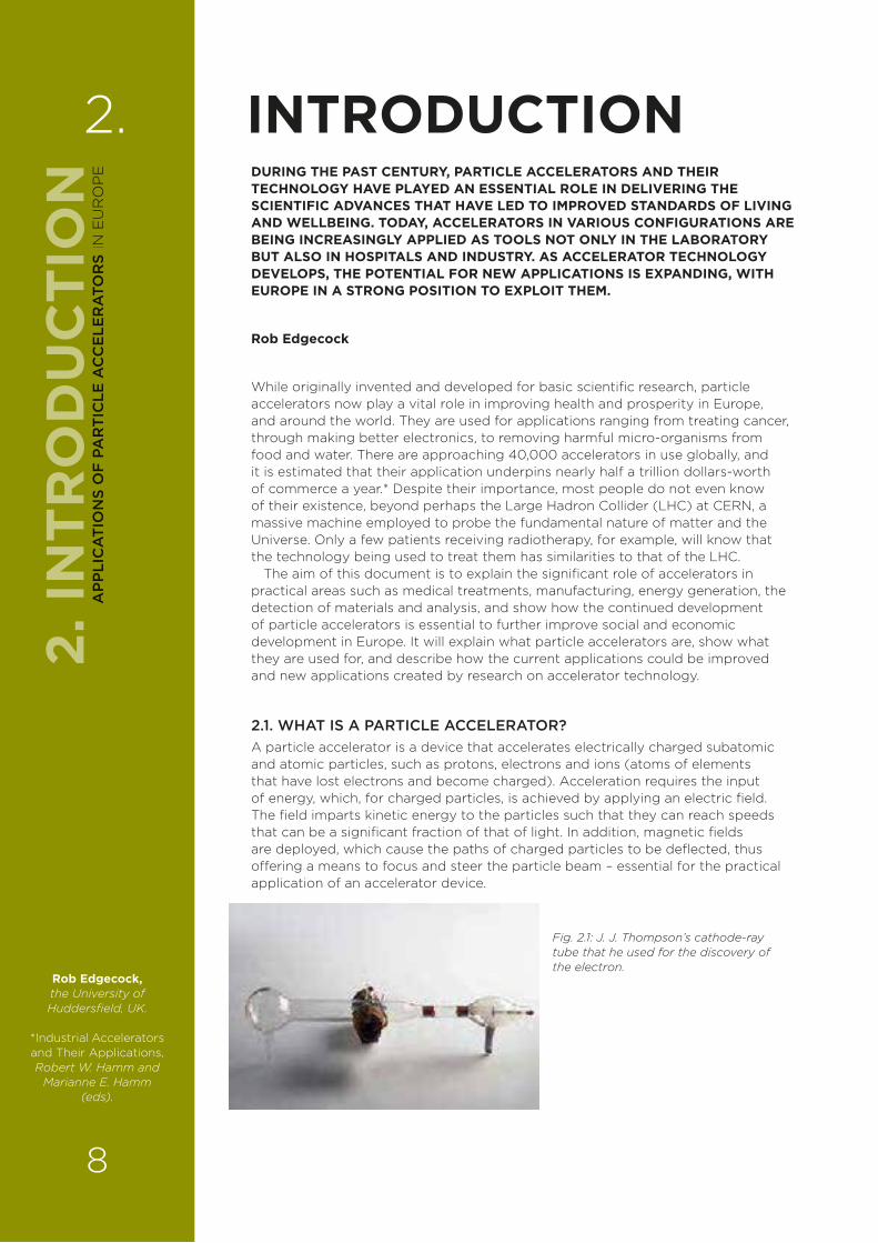
2.1. WHAT IS A PARTICLE ACCELERATOR?A particle accelerator is a device that accelerates electrically charged subatomic and atomic particles, such as protons, electrons and ions (atoms of elements that have lost electrons and become charged). Acceleration requires the input of energy, which, for charged particles, is achieved by applying an electric field. The field imparts kinetic energy to the particles such that they can reach speeds that can be a significant fraction of that of light. In addition, magnetic fields are deployed, which cause the paths of charged particles to be deflected, thus o¥ering a means to focus and steer the particle beam – essential for the practical application of an accelerator device.
2. INTRODUCTION
Fig. 2.1: J. J. Thompson’s cathode-ray tube that he used for the discovery of the electron.
Rob Edgecock, the University of Huddersfield, UK.
*Industrial Accelerators and Their Applications, Robert W. Hamm and
Marianne E. Hamm (eds).
2. IN
TRO
DU
CTI
ON
8
AP
PLI
CA
TIO
NS
OF
PA
RT
ICLE
AC
CE
LER
ATO
RS
IN E
UR
OP
E
2.2. HOW DO PARTICLE ACCELERATORS WORK?2.2.1. ELECTROSTATIC ACCELERATIONThe simplest way of accelerating particles is to have two sets of electrodes with a constant voltage di¥erence between them. The particles are then accelerated between the electrode plates in the electric field created by the voltage. The first accelerator to employ this technique was built by the British physicist, J. J. Thompson, in 1897, and its use resulted in the discovery of the electron (Fig. 2.1). The cathode-ray tube found in old television sets is a practical example of this approach.
The problem with this type of accelerator is that to reach ever higher energies, the voltage must be increased, and it becomes more di§cult to avoid electrical breakdown between the electrodes (with the resulting typical sparking). Various configurations, based on this electrostatic type of acceleration, including the so-called voltage multiplier and the famous Van de Graa¥ accelerator, are used to increase the energy that can be obtained, but the practical limit via this technique is 5 MeV.
These types of electrostatic, or DC, accelerators are the most commonly employed. This is because they are not only simple to operate but also constantly accelerate particles, making it possible to produce a large beam current – which is useful for many applications.
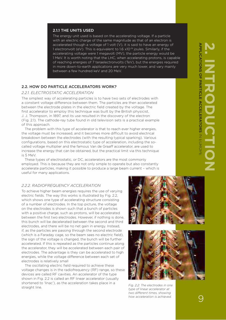
2.2.2. RADIOFREQUENCY ACCELERATIONTo achieve higher beam energies requires the use of varying electric fields. The way this works is illustrated by Fig. 2.2, which shows one type of accelerating structure consisting of a number of electrodes. In the top picture, the voltage on the electrodes is shown such that a bunch of particles with a positive charge, such as protons, will be accelerated between the first two electrodes. However, if nothing is done, this bunch will be decelerated between the second and third electrodes, and there will be no net gain in energy. Instead, if, as the particles are passing through the second electrode (which is a Faraday cage, so the beam sees no electric field), the sign of the voltage is changed, the bunch will be further accelerated. If this is repeated as the particles continue along the accelerator, they will be accelerated between each pair of electrodes. The advantage is they can be accelerated to high energies, while the voltage di¥erence between each set of electrodes is relatively small
The oscillating electric field required to achieve these voltage changes is in the radiofrequency (RF) range, so these devices are called RF cavities. An accelerator of the type shown in Fig. 2.2 is called an RF linear accelerator (usually shortened to ‘linac’), as the acceleration takes place in a straight line.2.2.3. COMPONENTS OF A MODERN ACCELERATOR
2.1.1 THE UNITS USEDThe energy unit used is based on the accelerating voltage. If a particle with an electric charge of the same magnitude as that of an electron is accelerated though a voltage of 1 volt (V), it is said to have an energy of 1 electronvolt (eV). This is equivalent to 1.6 x10⁻¹⁹ joules. Similarly, if the accelerating voltage were 1 megavolt (MV), the particle energy would be 1 MeV. It is worth noting that the LHC, when accelerating protons, is capable of reaching energies of 7 teraelectronvolts (TeV), but the energies required in more down-to-earth applications are very much lower, and vary mainly between a few hundred keV and 20 MeV.
Fig. 2.2: The electrodes in one type of linear accelerator at two di�erent times, showing how acceleration is achieved.
2. INTR
OD
UC
TION
9
AP
PLIC
AT
ION
S OF
PAR
TIC
LE A
CC
ELE
RA
TOR
S IN E
UR
OP
E
2.2.3 COMPONENTS OF A MODERN ACCELERATOR LAYOUTAn accelerator thus consists of:
› A particle production and injection system;
› An accelerating system complete with RF cavities to accelerate the beam;
› Magnets to control the direction and size of the beam;
› The accelerated beam is then ejected from the accelerator for use in selected applications.
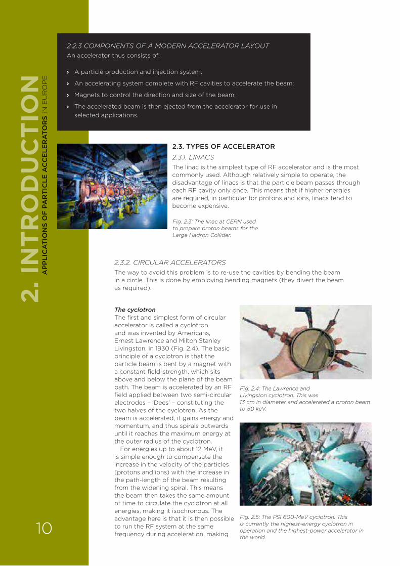
2.3. TYPES OF ACCELERATOR2.3.1. LINACSThe linac is the simplest type of RF accelerator and is the most commonly used. Although relatively simple to operate, the disadvantage of linacs is that the particle beam passes through each RF cavity only once. This means that if higher energies are required, in particular for protons and ions, linacs tend to become expensive.
Fig. 2.3: The linac at CERN used to prepare proton beams for the Large Hadron Collider.
2.3.2. CIRCULAR ACCELERATORSThe way to avoid this problem is to re-use the cavities by bending the beam in a circle. This is done by employing bending magnets (they divert the beam as required).
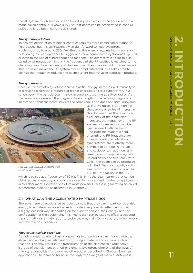
The cyclotronThe first and simplest form of circular accelerator is called a cyclotron and was invented by Americans, Ernest Lawrence and Milton Stanley Livingston, in 1930 (Fig. 2.4). The basic principle of a cyclotron is that the particle beam is bent by a magnet with a constant field-strength, which sits above and below the plane of the beam path. The beam is accelerated by an RF field applied between two semi-circular electrodes – ‘Dees’ – constituting the two halves of the cyclotron. As the beam is accelerated, it gains energy and momentum, and thus spirals outwards until it reaches the maximum energy at the outer radius of the cyclotron.
For energies up to about 12 MeV, it is simple enough to compensate the increase in the velocity of the particles (protons and ions) with the increase in the path-length of the beam resulting from the widening spiral. This means the beam then takes the same amount of time to circulate the cyclotron at all energies, making it isochronous. The advantage here is that it is then possible to run the RF system at the same frequency during acceleration, making
Fig. 2.4: The Lawrence and Livingston cyclotron. This was 13 cm in diameter and accelerated a proton beam to 80 keV.
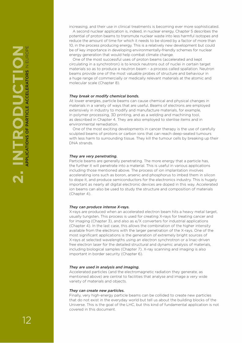
Fig. 2.5: The PSI 600-MeV cyclotron. This is currently the highest-energy cyclotron in operation and the highest-power accelerator in the world.
2. IN
TRO
DU
CTI
ON
10
AP
PLI
CA
TIO
NS
OF
PA
RT
ICLE
AC
CE
LER
ATO
RS
IN E
UR
OP
E
the RF system much simpler. In addition, it is possible to run the accelerator in a mode called continuous wave (CW), so that beam can be accelerated in each RF pulse and large beam currents delivered.
The synchrocyclotronTo achieve acceleration at higher energies requires more complicated magnetic field shapes, but it is still reasonably straightforward to keep cyclotrons isochronous up to around 230 MeV. Beyond this energy requires high magnetic-field strengths, leading either to bigger and more complicated cyclotrons (Fig. 2.5) or even to the use of superconducting magnets. The alternative is to go to a so-called synchrocyclotron. In this, the frequency of the RF cavities is matched to the changing revolution frequency of the beam, much as in a synchrotron (see below). This, however, makes the RF system more complicated and, as it takes time to change the frequency, reduces the beam current that the accelerator can produce.
The synchrotron Because the size of a cyclotron increases as the energy increases, a di¥erent type of circular accelerator is required at higher energies. This is a synchrotron. In a synchrotron, the particle beam travels around a closed ring at a fixed radius. As the beam is accelerated, the magnetic field strength in the bending magnets is increased so that the beam stays at the same radius and does not spiral outwards,
as in a cyclotron. In addition, for the particle energies of interest in this document, as the revolution frequency of the beam also increases, the frequency of the RF system is increased so that it is synchronised with the beam.
As both the magnetic field strength and RF frequency are changed during acceleration, synchrotrons are relatively more complex to operate than linacs and cyclotrons. In addition, as it takes time to ramp the magnets up and down, the frequency with which the beam can be produced is limited. The most rapidly cycling synchrotron in the world is at the ISIS neutron facility in the UK,
which is pulsed at a frequency of 50 Hz. This limits the beam current that can be obtained. As a result, synchrotrons are used for only a small number of applications in this document. However, one of its most powerful uses is in generating so-called synchrotron radiation as described in Chapter 7.
2.4. WHAT CAN THE ACCELERATED PARTICLES DO?The advantage of accelerated particle beams is that they can impart considerable energy to a material or object so as to create a very specific e¥ect, and often in a highly localised way, depending on the type of particle, their energy and the configuration of the equipment. This means they can be used to e¥ect a selected transformation in a material, or to probe the material’s form, structure or behaviour with microscopic precision.
They cause nuclear reactions.At high energies, particle beams – specifically of protons – can interact with the atomic nuclei of a given element constituting a material and cause a nuclear reaction. This may result in the transmutation of the element to a radioactive isotope of that element or another element. Cyclotrons o¥er one of the ways of making radionuclides for use in radiotherapy, as described in Chapter 3 on health applications. The demand for an increasingly wide range of medical isotopes is
2. INTR
OD
UC
TION
Fig. 2.6: The SOLEIL synchrotron Saint-Aubin, France.
11
AP
PLIC
AT
ION
S OF
PAR
TIC
LE A
CC
ELE
RA
TOR
S IN E
UR
OP
E
increasing, and their use in clinical treatments is becoming ever more sophisticated. A second nuclear application is, indeed, in nuclear energy. Chapter 5 describes the
potential of proton beams to transmute nuclear waste into less harmful isotopes and reduce the amount of time for which it needs to be stored by a factor of more than 10, in the process producing energy. This is a relatively new development but could be of key importance in developing environmentally-friendly schemes for nuclear energy generation that would help combat climate change.
One of the most successful uses of proton beams (accelerated and kept circulating in a synchrotron) is to knock neutrons out of nuclei in certain target materials so as to produce a neutron beam – a process called spallation. Neutron beams provide one of the most valuable probes of structure and behaviour in a huge range of commercially or medically relevant materials at the atomic and molecular scale (Chapter 8).
They break or modify chemical bonds. At lower energies, particle beams can cause chemical and physical changes in materials in a variety of ways that are useful. Beams of electrons are employed extensively in industry to modify and manufacture materials, for example, in polymer processing, 3D printing, and as a welding and machining tool, as described in Chapter 4. They are also employed to sterilise items and in environmental remediation.
One of the most exciting developments in cancer therapy is the use of carefully sculpted beams of protons or carbon ions that can reach deep-seated tumours with less harm to surrounding tissue. They kill the tumour cells by breaking up their DNA strands.
They are very penetrating.Particle beams are generally penetrating. The more energy that a particle has, the further it will penetrate into a material. This is useful in various applications including those mentioned above. The process of ion implantation involves accelerating ions such as boron, arsenic and phosphorus to imbed them in silicon to dope it, and produce semiconductors for the electronics industry. This is hugely important as nearly all digital electronic devices are doped in this way. Accelerated ion beams can also be used to study the structure and composition of materials (Chapter 4).
They can produce intense X-rays.X-rays are produced when an accelerated electron beam hits a heavy metal target, usually tungsten. This process is used for creating X-rays for treating cancer and for imaging (Chapter 3), and also as e/X converters for industrial applications (Chapter 4). In the last case, this allows the combination of the higher intensity available from the electrons with the larger penetration of the X-rays. One of the most significant applications is the generation of extremely bright sources of X-rays at selected wavelengths using an electron synchrotron or a linac-driven free electron laser for the detailed structural and dynamic analysis of materials, including biological samples (Chapter 7). X-ray scanning and imaging is also important in border security (Chapter 6).
They are used in analysis and imaging.Accelerated particles (and the electromagnetic radiation they generate, as mentioned above) are central to facilities that analyse and image a very wide variety of materials and objects.
They can create new particles.Finally, very high-energy particle beams can be collided to create new particles that do not exist in the everyday world but tell us about the building blocks of the Universe. This is the goal of the LHC, but this kind of fundamental application is not covered in this document.
2. IN
TRO
DU
CTI
ON
12
AP
PLI
CA
TIO
NS
OF
PA
RT
ICLE
AC
CE
LER
ATO
RS
IN E
UR
OP
E
2.5. THE EVERYDAY APPLICATIONS OF PARTICLE ACCELERATORSWithout accelerators, major advances in the biosciences of the past 50 years would not have happened, and future developments in accelerator technology will stimulate further a better understanding of living processes, leading to new medicines and therapies. Similarly, accelerated particle beams will continue to play a growing role in the analysis and fabrication of commercially important products, particularly in the development of the next generation of electronics, and advanced engineering and smart materials. Technology based on accelerators is also helping to solve environmental problems, and can help provide solutions to dealing with climate change (via ‘greener’ nuclear energy, for example).
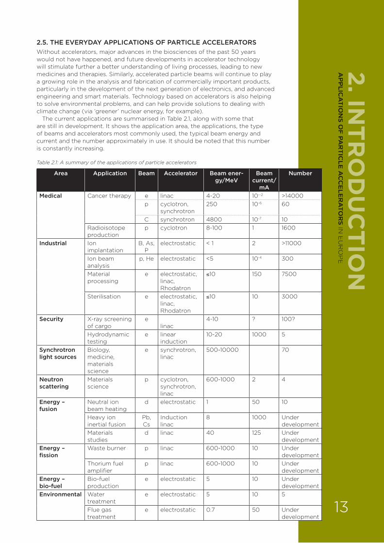
The current applications are summarised in Table 2.1, along with some that are still in development. It shows the application area, the applications, the type of beams and accelerators most commonly used, the typical beam energy and current and the number approximately in use. It should be noted that this number is constantly increasing.
Table 2.1: A summary of the applications of particle accelerators
Area Application Beam Accelerator Beam ener-gy/MeV
Beam current/
mA
Number
Medical Cancer therapy e linac 4-20 10--2 >14000p cyclotron,
synchrotron250 10-6 60
C synchrotron 4800 10-7 10Radioisotope production
p cyclotron 8-100 1 1600
Industrial Ion implantation
B, As, P
electrostatic < 1 2 >11000
Ion beam analysis
p, He electrostatic <5 10-4 300
Material processing
e electrostatic, linac, Rhodatron
≤10 150 7500
Sterilisation e electrostatic, linac, Rhodatron
≤10 10 3000
Security X-ray screening of cargo
elinac
4-10 ? 100?
Hydrodynamic testing
e linear induction
10-20 1000 5
Synchrotron light sources
Biology, medicine, materials science
e synchrotron, linac
500-10000 70
Neutron scattering
Materials science
p cyclotron, synchrotron, linac
600-1000 2 4
Energy – fusion
Neutral ion beam heating
d electrostatic 1 50 10
Heavy ion inertial fusion
Pb, Cs
Induction linac
8 1000 Under development
Materials studies
d linac 40 125 Under development
Energy – fission
Waste burner p linac 600-1000 10 Under development
Thorium fuel amplifier
p linac 600-1000 10 Under development
Energy – bio-fuel
Bio-fuel production
e electrostatic 5 10 Under development
Environmental Water treatment
e electrostatic 5 10 5
Flue gas treatment
e electrostatic 0.7 50 Under development
2. INTR
OD
UC
TION
13
AP
PLIC
AT
ION
S OF
PAR
TIC
LE A
CC
ELE
RA
TOR
S IN E
UR
OP
E
2.6. DEVELOPMENTS IN ACCELERATOR TECHNOLOGYThe current applications, especially those used in healthcare and industry, tend to use rather old technology, and their performance, especially for newer applications, can be limited by this. Much research is now going into developing more e§cient, better performing and more compact machines exploiting new approaches to particle acceleration. Inexpensive table-top accelerators for use in medicine, or in industry and commerce, are an achievable and desirable goal, and could lead to novel applications not yet thought of.
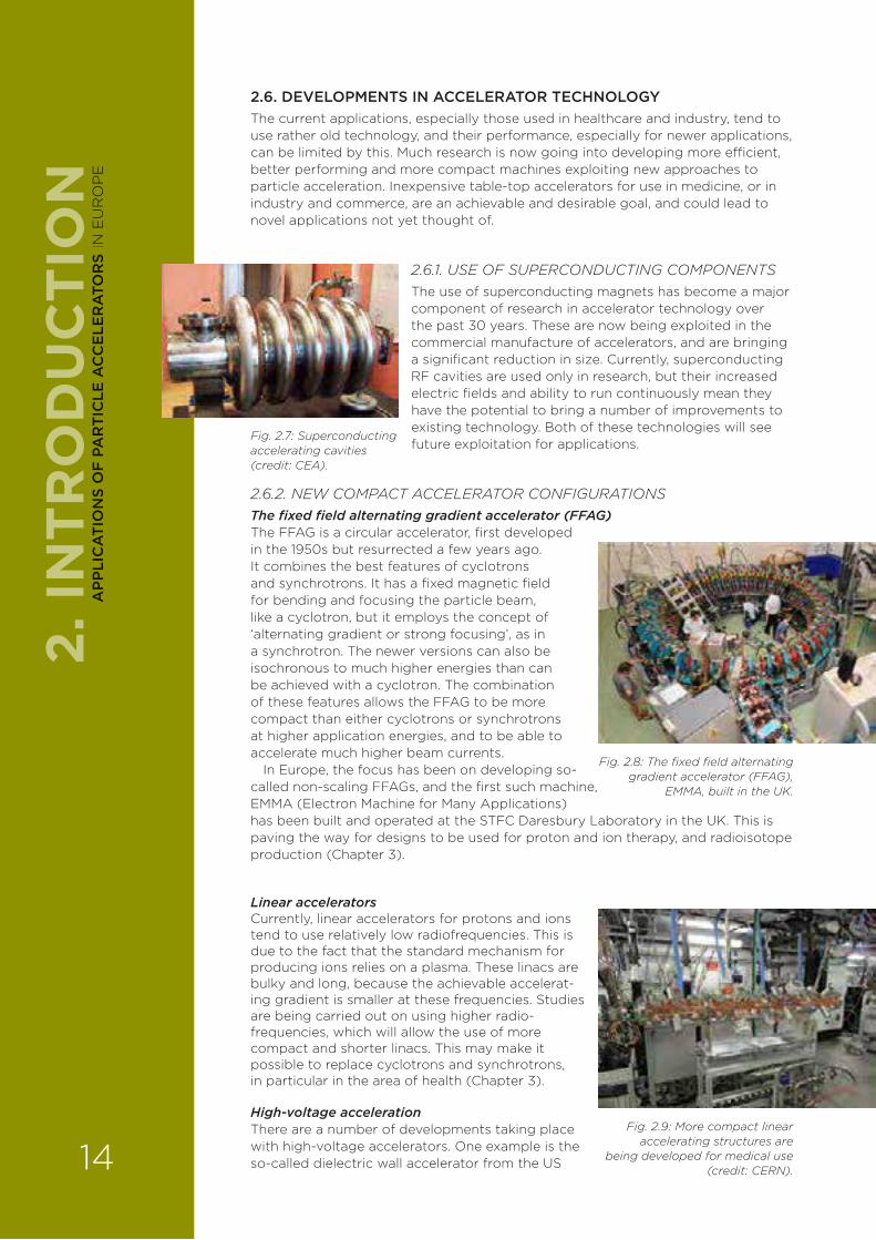
2.6.1. USE OF SUPERCONDUCTING COMPONENTSThe use of superconducting magnets has become a major component of research in accelerator technology over the past 30 years. These are now being exploited in the commercial manufacture of accelerators, and are bringing a significant reduction in size. Currently, superconducting RF cavities are used only in research, but their increased electric fields and ability to run continuously mean they have the potential to bring a number of improvements to existing technology. Both of these technologies will see future exploitation for applications.
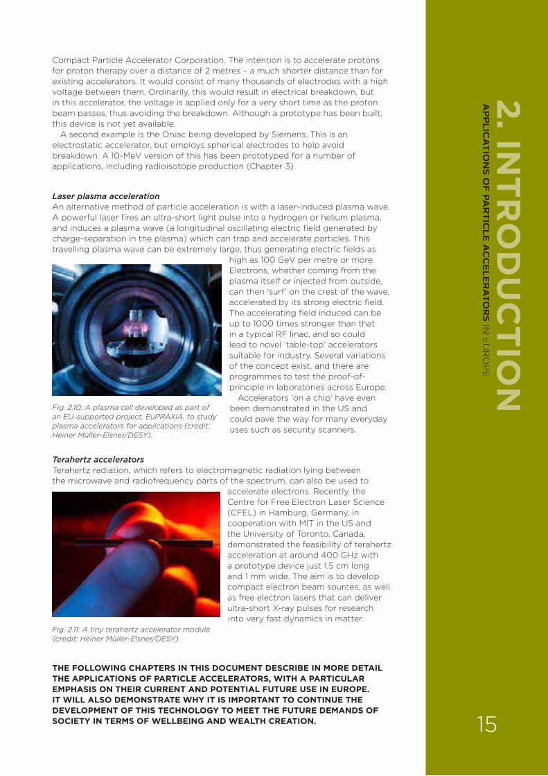
2.6.2. NEW COMPACT ACCELERATOR CONFIGURATIONSThe fixed field alternating gradient accelerator (FFAG) The FFAG is a circular accelerator, first developed in the 1950s but resurrected a few years ago. It combines the best features of cyclotrons and synchrotrons. It has a fixed magnetic field for bending and focusing the particle beam, like a cyclotron, but it employs the concept of ‘alternating gradient or strong focusing’, as in a synchrotron. The newer versions can also be isochronous to much higher energies than can be achieved with a cyclotron. The combination of these features allows the FFAG to be more compact than either cyclotrons or synchrotrons at higher application energies, and to be able to accelerate much higher beam currents.
In Europe, the focus has been on developing so-called non-scaling FFAGs, and the first such machine, EMMA (Electron Machine for Many Applications) has been built and operated at the STFC Daresbury Laboratory in the UK. This is paving the way for designs to be used for proton and ion therapy, and radioisotope production (Chapter 3).
Linear acceleratorsCurrently, linear accelerators for protons and ions tend to use relatively low radiofrequencies. This is due to the fact that the standard mechanism for producing ions relies on a plasma. These linacs are bulky and long, because the achievable accelerat-ing gradient is smaller at these frequencies. Studies are being carried out on using higher radio- frequencies, which will allow the use of more compact and shorter linacs. This may make it possible to replace cyclotrons and synchrotrons, in particular in the area of health (Chapter 3).
High-voltage accelerationThere are a number of developments taking place with high-voltage accelerators. One example is the so-called dielectric wall accelerator from the US
Fig. 2.7: Superconducting accelerating cavities (credit: CEA).
Fig. 2.8: The fixed field alternating gradient accelerator (FFAG),
EMMA, built in the UK.
Fig. 2.9: More compact linear accelerating structures are
being developed for medical use (credit: CERN).
2. IN
TRO
DU
CTI
ON
14
AP
PLI
CA
TIO
NS
OF
PA
RT
ICLE
AC
CE
LER
ATO
RS
IN E
UR
OP
E
Compact Particle Accelerator Corporation. The intention is to accelerate protons for proton therapy over a distance of 2 metres – a much shorter distance than for existing accelerators. It would consist of many thousands of electrodes with a high voltage between them. Ordinarily, this would result in electrical breakdown, but in this accelerator, the voltage is applied only for a very short time as the proton beam passes, thus avoiding the breakdown. Although a prototype has been built, this device is not yet available.
A second example is the Oniac being developed by Siemens. This is an electrostatic accelerator, but employs spherical electrodes to help avoid breakdown. A 10-MeV version of this has been prototyped for a number of applications, including radioisotope production (Chapter 3).
Laser plasma accelerationAn alternative method of particle acceleration is with a laser-induced plasma wave. A powerful laser fires an ultra-short light pulse into a hydrogen or helium plasma, and induces a plasma wave (a longitudinal oscillating electric field generated by charge-separation in the plasma) which can trap and accelerate particles. This travelling plasma wave can be extremely large, thus generating electric fields as
high as 100 GeV per metre or more. Electrons, whether coming from the plasma itself or injected from outside, can then ‘surf’ on the crest of the wave, accelerated by its strong electric field. The accelerating field induced can be up to 1000 times stronger than that in a typical RF linac, and so could lead to novel ‘table-top’ accelerators suitable for industry. Several variations of the concept exist, and there are programmes to test the proof-of-principle in laboratories across Europe.
Accelerators ‘on a chip’ have even been demonstrated in the US and could pave the way for many everyday uses such as security scanners.
Terahertz acceleratorsTerahertz radiation, which refers to electromagnetic radiation lying between the microwave and radiofrequency parts of the spectrum, can also be used to
accelerate electrons. Recently, the Centre for Free Electron Laser Science (CFEL) in Hamburg, Germany, in cooperation with MIT in the US and the University of Toronto, Canada, demonstrated the feasibility of terahertz acceleration at around 400 GHz with a prototype device just 1.5 cm long and 1 mm wide. The aim is to develop compact electron beam sources, as well as free electron lasers that can deliver ultra-short X-ray pulses for research into very fast dynamics in matter.
THE FOLLOWING CHAPTERS IN THIS DOCUMENT DESCRIBE IN MORE DETAIL THE APPLICATIONS OF PARTICLE ACCELERATORS, WITH A PARTICULAR EMPHASIS ON THEIR CURRENT AND POTENTIAL FUTURE USE IN EUROPE. IT WILL ALSO DEMONSTRATE WHY IT IS IMPORTANT TO CONTINUE THE DEVELOPMENT OF THIS TECHNOLOGY TO MEET THE FUTURE DEMANDS OF SOCIETY IN TERMS OF WELLBEING AND WEALTH CREATION.
2. INTR
OD
UC
TION
Fig. 2.10: A plasma cell developed as part of an EU-supported project, EuPRAXIA, to study plasma accelerators for applications (credit: Heiner Müller-Elsner/DESY).
Fig. 2.11: A tiny terahertz accelerator module (credit: Heiner Müller-Elsner/DESY).
15
AP
PLIC
AT
ION
S OF
PAR
TIC
LE A
CC
ELE
RA
TOR
S IN E
UR
OP
E

Ondrej Lebeda, Nuclear Physics
Institute of the Czech Academy of Sciences,
Czech Republic.
Alejandro Mazal, Institut Curie, Paris
France.
Hywel Owen, University of
Manchester/Cockcroft Institute, UK.
Additional contributors: Oxana Actis
(PSI, Switzerland), Alberto Degiovanni (CERN, Switzerland)
and Jay Flanz
(Massachusetts General Hospital, US).
THE POTENTIAL OF ACCELERATOR-RELIANT THERAPY AND DIAGNOSTIC TECHNIQUES HAS INCREASED CONSIDERABLY OVER PAST DECADES, PLAYING AN INCREASINGLY IMPORTANT ROLE IN IDENTIFYING AND CURING OTHERWISE DIFFICULT-TO-TREAT CANCERS, AS WELL AS IN UNDERSTANDING HOW MAJOR ORGANS SUCH AS THE BRAIN FUNCTION AND THUS THE UNDERLYING CAUSES OF DISEASES OF GROWING SIGNIFICANCE TO SOCIETY, SUCH AS DEMENTIA.
Ondrej Lebeda, Alejandro Mazal and Hywel Owen
3.1. INTRODUCTION Energetic particles – high-energy photons (X-rays and gamma-rays), electrons, protons, neutrons, various atomic nuclei and more exotic species – provide an indispensable tool in improving human health. Because they penetrate living tissue, they can act as detecting agents in the non-invasive imaging of internal organs, or at higher energies selectively destroy malignant tissue. Such particles may be delivered as precisely sculpted beams in carefully planned therapeutic procedures, or be generated by radioactive isotopes (radionuclides) that have been combined with a suitable chemical or biological agent and injected into the body. Known as radio-medicine, this field is growing rapidly because of its extremely e¥ective role in researching, diagnosing and curing a number of ubiquitous and life-threatening conditions; these include cancer, heart disease, and the diseases of old age, which only a few decades ago were thought di§cult or impossible to treat. Today, millions of procedures, in which radio-medicine plays the central part, are carried out across the world – and the demand is growing.
The generation of particle beams, for example protons, requires an accelerator, and while some radio-isotopes are made in a nuclear reactor, there are increasingly strong arguments for developing more dedicated accelerators for isotope production. In both cases, there are considerable opportunities to intensify R&D programmes that will expand the clinical use of accelerators by developing novel designs that make them more compact, e§cient and cost-e¥ective – and also versatile enough to meet the needs of specific treatments. Below, we describe the expanding role of accelerators in improving human health and the future challenges for accelerator R&D in meeting these requirements.
3.2. RADIOTHERAPY3.2.1. STATE OF THE ARTCancer is currently responsible for just over a quarter of all deaths in Europe. The incidence of the disease is rising, with nearly one in two people in Europe now su¥ering from it at some point during their lives, largely due to the increasing age of the population. There are three main treatments for cancer, with a fourth rapidly developing. They are:
› surgery;
› radiotherapy;
› chemotherapy;
› immunotherapy.
Around a half of all cancer patients will receive some kind of radiotherapy as part of their treatment, and the most common external radiotherapy techniques intrinsically depend on the use of an accelerator. Treatments may be with photons (X-rays) or particle-based (protons, ions, neutrons, electrons or even more exotic particles).
3. ACCELERATORS AND HEALTH
3. H
EA
LTH
16
AP
PLI
CA
TIO
NS
OF
PA
RT
ICLE
AC
CE
LER
ATO
RS
IN E
UR
OP
E
3.2.2. X-RAY THERAPYX-rays provided the first radiotherapeutic technique used clinically; shortly after Wilhelm Roentgen had discovered X-rays in 1895, Austrians Leopold Freund and Eduard Schi¥ were employing them to treat skin diseases, while Herbert Jackson – a chemist at Kings College London in the UK – developed the first focusing system to control better the delivery of those X-ray beams.
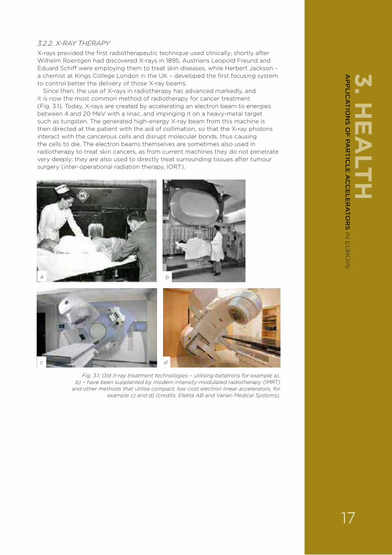
Since then, the use of X-rays in radiotherapy has advanced markedly, and it is now the most common method of radiotherapy for cancer treatment (Fig. 3.1). Today, X-rays are created by accelerating an electron beam to energies between 4 and 20 MeV with a linac, and impinging it on a heavy-metal target such as tungsten. The generated high-energy X-ray beam from this machine is then directed at the patient with the aid of collimation, so that the X-ray photons interact with the cancerous cells and disrupt molecular bonds, thus causing the cells to die. The electron beams themselves are sometimes also used in radiotherapy to treat skin cancers, as from current machines they do not penetrate very deeply; they are also used to directly treat surrounding tissues after tumour surgery (inter-operational radiation therapy, IORT).
a b
c d
Fig. 3.1: Old X-ray treatment technologies – utilising betatrons for example a), b) – have been supplanted by modern intensity-modulated radiotherapy (IMRT)
and other methods that utilise compact, low-cost electron linear accelerators, for example c) and d) (credits: Elekta AB and Varian Medical Systems).
3. HE
ALTH
17
AP
PLIC
AT
ION
S OF
PAR
TIC
LE A
CC
ELE
RA
TOR
S IN E
UR
OP
E
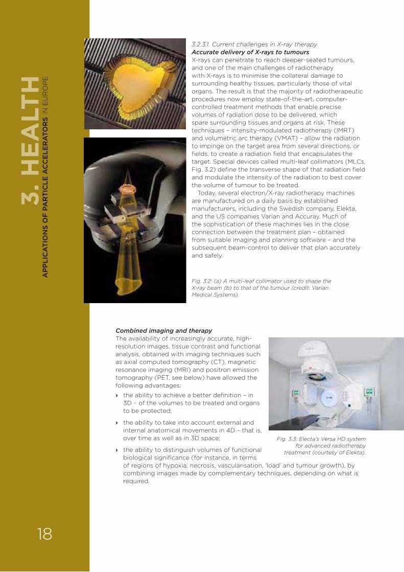
3.2.3.1. Current challenges in X-ray therapyAccurate delivery of X-rays to tumoursX-rays can penetrate to reach deeper-seated tumours, and one of the main challenges of radiotherapy with X-rays is to minimise the collateral damage to surrounding healthy tissues, particularly those of vital organs. The result is that the majority of radiotherapeutic procedures now employ state-of-the-art, computer-controlled treatment methods that enable precise volumes of radiation dose to be delivered, which spare surrounding tissues and organs at risk. These techniques – intensity-modulated radiotherapy (IMRT) and volumetric arc therapy (VMAT) – allow the radiation to impinge on the target area from several directions, or fields, to create a radiation field that encapsulates the target. Special devices called multi-leaf collimators (MLCs, Fig. 3.2) define the transverse shape of that radiation field and modulate the intensity of the radiation to best cover the volume of tumour to be treated.
Today, several electron/X-ray radiotherapy machines are manufactured on a daily basis by established manufacturers, including the Swedish company, Elekta, and the US companies Varian and Accuray. Much of the sophistication of these machines lies in the close connection between the treatment plan – obtained from suitable imaging and planning software – and the subsequent beam-control to deliver that plan accurately and safely.
Fig. 3.2: (a) A multi-leaf collimator used to shape the X-ray beam (b) to that of the tumour (credit: Varian Medical Systems).
Combined imaging and therapyThe availability of increasingly accurate, high-resolution images, tissue contrast and functional analysis, obtained with imaging techniques such as axial computed tomography (CT), magnetic resonance imaging (MRI) and positron emission tomography (PET, see below) have allowed the following advantages:
› the ability to achieve a better definition – in 3D – of the volumes to be treated and organs to be protected;
› the ability to take into account external and internal anatomical movements in 4D – that is, over time as well as in 3D space;
› the ability to distinguish volumes of functional biological significance (for instance, in terms of regions of hypoxia, necrosis, vascularisation, ‘load’ and tumour growth), by combining images made by complementary techniques, depending on what is required.
Fig. 3.3: Electa’s Versa HD system for advanced radiotherapy
treatment (courtesy of Elekta).
3. H
EA
LTH
18
AP
PLI
CA
TIO
NS
OF
PA
RT
ICLE
AC
CE
LER
ATO
RS
IN E
UR
OP
E

Personalised planningFurther improvements include items available to reduce the risk that a treatment di¥ers from the prescription, for example:
› ‘robust’ treatment planning, taking into account uncertainties;
› the use of images in the treatment room – image-guided radiation therapy (IGRT);
› the control of the doses administered to patients (dosimetry ‘in vivo’ and/or ‘transit’);
› adapting treatments to changes such as patient morphology (‘adaptive radiotherapy’).
3.2.3.2. The future for X-ray treatmentsUsing the UK as an example with its population of around 64 million people, about 130,000 patients are treated each year with around 300 linacs; more than half of these treatments are for breast and prostate treatment. Each X-ray treatment machine achieves around 7000 ‘attendances’ a year. A useful rule-of-thumb is that radiotherapy demands treatment dose rates measured in several grays per minute (Gy/min).
Fig. 3.4: The MR-linac, developed by Elekta, consists of a linear accelerator equipped with multi-leaf collimator technology for accurate radiotherapy dosage, combined with a high-field MR
imaging system. The MR-linac is work in progress and is not available for sale or distribution (courtesy of Elekta).
In Europe and more widely, capacity needs have been forecast in several studies that include the EU-funded projects QUARTS (Quantification of Radiation Therapy Infrastructure and Sta§ng Needs) and HERO (Health Economics in Radiation Oncology). The demand for such facilities is steadily increasing, with most new machines being specified to have an IMRT or a similar delivery method, and with many incorporating image-guidance. A notable new technology entering clinical use at the moment is the so-called MR-linac, which provides near-simultaneous magnetic resonance (MR) imaging and radiotherapy treatment.
3.2.3. PARTICLE THERAPYTherapies using accelerated beams of particles have growing potential in dealing with di§cult-to-treat tumours, for example, because of the risk of damaging neighbouring sensitive tissues such as the spine or certain organs. Also, some treatments may benefit from the use of particles that deliver doses with a greater radiobiological e¥ectiveness (RBE), notably carbon ions.
3. HE
ALTH
19
AP
PLIC
AT
ION
S OF
PAR
TIC
LE A
CC
ELE
RA
TOR
S IN E
UR
OP
E
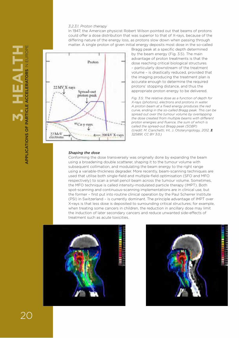
3.2.3.1. Proton therapyIn 1947, the American physicist Robert Wilson pointed out that beams of protons could o¥er a dose distribution that was superior to that of X-rays, because of the di¥ering nature of the energy loss, as protons slow down when passing through matter. A single proton of given initial energy deposits most dose in the so-called
Bragg peak at a specific depth determined by the beam energy (Fig. 3.5). The main advantage of proton treatments is that the dose reaching critical biological structures – particularly downstream of the treatment volume – is drastically reduced, provided that the imaging producing the treatment plan is accurate enough to determine the required protons’ stopping distance, and thus the appropriate proton energy to be delivered.
Shaping the doseConforming the dose transversely was originally done by expanding the beam using a broadening double scatterer, shaping it to the tumour volume with subsequent collimation, and modulating the beam energy to the right range using a variable-thickness degrader. More recently, beam-scanning techniques are used that utilise both single-field and multiple-field optimisation (SFO and MFO respectively) to scan a small pencil beam across the tumour volume. Sometimes, the MFO technique is called intensity-modulated particle therapy (IMPT). Both spot-scanning and continuous-scanning implementations are in clinical use, but the former – first put into routine clinical operation by the Paul Scherrer Institute (PSI) in Switzerland – is currently dominant. The principle advantage of IMPT over X-rays is that less dose is deposited to surrounding critical structures; for example, when treating some cancers in children, the reduction in ancillary dose may limit the induction of later secondary cancers and reduce unwanted side-e¥ects of treatment such as acute toxicities.
Fig. 3.5: The relative dose as a function of depth for X-rays (photons), electrons and protons in water. A proton beam at a fixed energy produces the red curve, ending in the so-called Bragg peak. This can be spread out over the tumour volume by overlapping the dose created from multiple beams with di�erent proton energies and fluence, the sum of which is called the spread-out Bragg peak (SOBP) (credit: M. Cianchetti, Int. J. Otolaryngology, 2012, 3, 325891, CC BY 3.0.)
3. H
EA
LTH
20
AP
PLI
CA
TIO
NS
OF
PA
RT
ICLE
AC
CE
LER
ATO
RS
IN E
UR
OP
E
Current accelerator and facility statusTo obtain a su§cient Bragg peak-depth for most adult treatments requires incident proton energies up to around 230 MeV (corresponding to a range of 33 cm in water). The required beam current at the patient is small when compared to other uses of particle accelerators; a maximum current around 10 nA during treatment is enough to enable modulated intensities such that a dose of 1 Gy may be delivered to a typical treatment volume of 1 litre in about 1 minute; this corresponds to about 50 billion protons. Such energies and dose rates are in principle obtainable from many types of accelerators, but in practice all current clinical systems utilise either fixed-energy cyclotrons (with a suitable downstream degrader to produce the correct energy), or variable-energy synchrotrons (where the extraction energy is changed).
The rapid growth in treatments seen today is being spearheaded by a number of commercial suppliers, and two major trends in treatment are clear. First, until recently the majority of patients were treated using protons derived from synchrotrons, but now this is reversed, with a greater fraction of patients being treated with beams from cyclotrons. Secondly, in the next few years, the majority of treatment rooms will o¥er beam-delivery systems with beam-scanning rather than with passive scattering.
The worldwide organisation promoting particle therapies – the Particle Therapy Co-Operative Group (PTCOG) – maintains up-to-date information on the use of particle therapy. Following the initial period starting in the 1950s when treatments were carried out in physics laboratories, today there are more than 60 dedicated centres around the world o¥ering particle therapy located principally at hospitals. More than 100,000 patients have now been treated.
Early laboratory-based particle therapy was studied at a number of centres worldwide. The first hospital-based proton therapy centre in the world was at the Clatterbridge Cancer Centre in the UK, which commenced patient treatment in 1989; however, this facility is limited by its 62-MeV cyclotron to delivering eye treatments to a depth of about 30 mm. The first high-energy, hospital-based centre was at the Loma Linda University Medical Center in California, US; the first hospital-based centre that was commercially produced was installed at the Massachusetts General Hospital, US. Proton therapy centres are now widely distributed across Europe, and high-energy facilities suitable for adult treatments are summarised in Table 3.1. Germany and Italy not only have the majority of proton centres but also o¥er the only ion-beam treatments currently available in Europe. Many new centres are currently under construction in Europe, as in the rest of the world (Table 3.2).
3. HE
ALTH
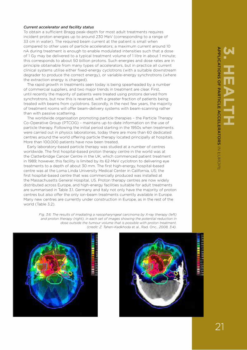
Fig. 3.6: The results of irradiating a nasopharyngeal carcinoma by X-ray therapy (left) and proton therapy (right), in each set of images showing the potential reduction in
dose outside the tumour volume that is possible with proton treatment. (credit: Z. Taheri-Kadkhoda et al., Rad. Onc., 2008, 3:4).
21
AP
PLIC
AT
ION
S OF
PAR
TIC
LE A
CC
ELE
RA
TOR
S IN E
UR
OP
E
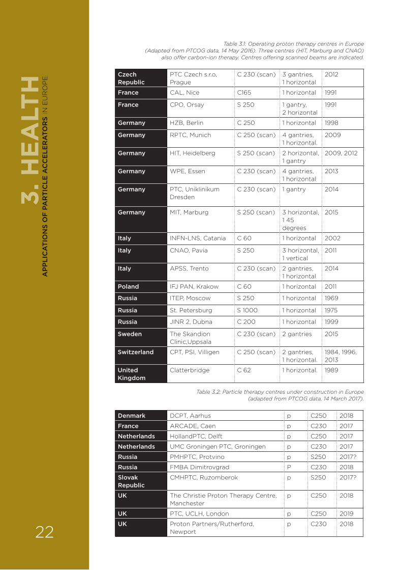
Table 3.1: Operating proton therapy centres in Europe (Adapted from PTCOG data, 14 May 2016). Three centres (HIT, Marburg and CNAO)
also o�er carbon-ion therapy. Centres o�ering scanned beams are indicated.
Czech Republic
PTC Czech s.r.o, Prague
C 230 (scan) 3 gantries, 1 horizontal
2012
France CAL, Nice C165 1 horizontal 1991
France CPO, Orsay S 250 1 gantry, 2 horizontal
1991
Germany HZB, Berlin C 250 1 horizontal 1998
Germany RPTC, Munich C 250 (scan) 4 gantries, 1 horizontal.
2009
Germany HIT, Heidelberg S 250 (scan) 2 horizontal, 1 gantry
2009, 2012
Germany WPE, Essen C 230 (scan) 4 gantries, 1 horizontal
2013
Germany PTC, Uniklinikum Dresden
C 230 (scan) 1 gantry 2014
Germany MIT, Marburg S 250 (scan) 3 horizontal, 1 45 degrees
2015
Italy INFN-LNS, Catania C 60 1 horizontal 2002
Italy CNAO, Pavia S 250 3 horizontal, 1 vertical
2011
Italy APSS, Trento C 230 (scan) 2 gantries, 1 horizontal
2014
Poland IFJ PAN, Krakow C 60 1 horizontal 2011
Russia ITEP, Moscow S 250 1 horizontal 1969
Russia St. Petersburg S 1000 1 horizontal 1975
Russia JINR 2, Dubna C 200 1 horizontal 1999
Sweden The Skandion Clinic,Uppsala
C 230 (scan) 2 gantries 2015
Switzerland CPT, PSI, Villigen C 250 (scan) 2 gantries, 1 horizontal.
1984, 1996, 2013
United Kingdom
Clatterbridge C 62 1 horizontal. 1989
Table 3.2: Particle therapy centres under construction in Europe (adapted from PTCOG data, 14 March 2017).
Denmark DCPT, Aarhus p C250 2018
France ARCADE, Caen p C230 2017
Netherlands HollandPTC, Delft p C250 2017
Netherlands UMC Groningen PTC, Groningen p C230 2017
Russia PMHPTC, Protvino p S250 2017?
Russia FMBA Dimitrovgrad P C230 2018
Slovak Republic
CMHPTC, Ruzomberok p S250 2017?
UK The Christie Proton Therapy Centre, Manchester
p C250 2018
UK PTC, UCLH, London p C250 2019
UK Proton Partners/Rutherford, Newport
p C230 2018
3. H
EA
LTH
22
AP
PLI
CA
TIO
NS
OF
PA
RT
ICLE
AC
CE
LER
ATO
RS
IN E
UR
OP
E
3.2.3.2. Ion and exotic particle therapiesCarbon ionsAs well as protons, the ions of heavier elements – especially carbon – have been used in radiotherapy. Sometimes known as hadron therapy, these ions o¥er distinct di¥erences in their biological e¥ect that may be advantageous for certain treatments. The RBE per unit of delivered dose is around 1.1 for protons (compared to 1.0 for X-rays generated from cobalt-60), but may be as high as 3 or more for carbon ions.
The downside is the greater di§culty in obtaining and directing these heavier ions onto the patient. Carbon ions require kinetic energies up to as much as 425 MeV per atomic mass unit (as in the Heidelberg Ion Beam Therapy Centre, HIT, in Germany), which corresponds to a beam rigidity (resistance to deflection by a magnetic field) of 6.57 Tm (tesla-metres); this is nearly three times larger than the 2.43-Tm rigidity of a 250-MeV proton beam with roughly the same stopping range. The greater rigidity means that stronger magnetic fields are required to direct the particles, which a¥ects the size of all the magnetic components in a carbon-
ion facility, and if normal-conducting magnets are used (limited to fields of around 1.8 T), this means that the accelerator source and delivery gantry has to be about three times bigger. For example, the Heidelberg gantry has a mass approaching 600 tonnes with a dipole bending radius of 3.65 metres. Higher-field, superconducting magnets must be used if the size is to be reduced (see below). Once delivered to the patient, the transverse scattering of carbon ions is significantly smaller, and, together with the increased RBE, may o¥er significant clinical benefits for some treatments.
For a variety of clinical, technical (and historical) reasons, carbon-ion treatment is currently the predominant ion in use today. Following the establishment of pioneering centres in Japan, a number of carbon-ion treatment centres have been constructed in Europe in recent years: most notably HIT in Germany, the National Centre of Oncological Hadrontherapy (CNAO) in Pavia, Italy, and MedAustron near Vienna in Austria. Currently, only synchrotrons have been routinely used for
clinical carbon treatment; this is because their greater ion-beam rigidity makes cyclotrons more di§cult to employ. However, recently there has been some debate as to the optimal future technology for ion therapy, with linacs and FFAG accelerators (fixed field alternating gradient) – as described in Chapter 2 – also being considered.
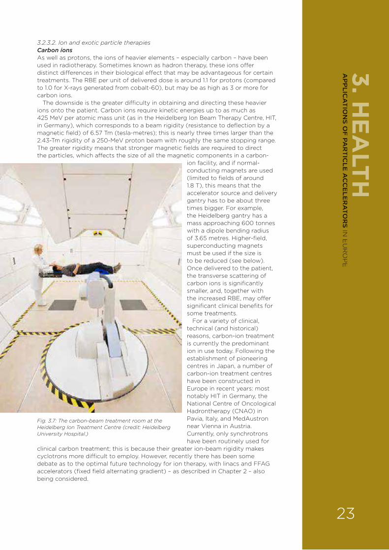
Fig. 3.7: The carbon-beam treatment room at the Heidelberg Ion Treatment Centre (credit: Heidelberg University Hospital.)
3. HE
ALTH
23
AP
PLIC
AT
ION
S OF
PAR
TIC
LE A
CC
ELE
RA
TOR
S IN E
UR
OP
E
Helium, oxygen and argon ionsThere are good arguments for investigating further which is the most appropriate ion type to be used for a particular radiotherapy treatment. Various ions have been studied in the past to determine their benefits, including early studies at the University of California at Berkeley and Harvard University in the US, Uppsala University in Sweden, the Institute for Theoretical and Experimental Physics (ITEP) in Moscow and St Petersburg State University in Russia, and the National Institute of Radiological Sciences (NIRS) in Japan. These have included ions such as those of helium, oxygen and argon (as well as carbon); at Berkeley, for example, a large research cyclotron was used to produce these ions.
Recently, there has been a renewed interest in the use of helium ions because of their lower transverse-scattering compared with that of protons, and because helium ions represent an intermediate step between protons and carbon ions in the required accelerator size. Some clinical testing has been carried out, but this is an immature topic deserving further study. There is also some interest in the use of radioactive ions such as carbon-11 (11C), which can provide both treatment and PET imaging from a single incident beam.
In terms of accelerator technology, generating ion beams such as those of helium requires a similar set-up to that needed for carbon beams: a suitable ion source, followed by a pre-injector and (usually) then a synchrotron. However, it should be noted that cyclotrons and linacs are also an option for generating the lighter helium ions.
Pions and antiprotonsMore exotic candidates such as pions and antiprotons have also been studied, where the so-called star dose from (matter–antimatter annihilation and other processes) may usefully augment the dose delivered at the end of the particle range. However, these star doses have generally been shown to be detrimental to the sharpness of the dose gradient on the distal edge of the Bragg peak. They also need a suitable nuclear reaction to make them, which requires an accelerated particle beam and a target that, especially in the case of antiprotons, is rather complex and costly. These factors limit any likely clinical application; therefore, despite these and other similar species having been studied, none is in routine clinical use today.
At present, the consensus view is that only carbon and helium ions are likely to be used widely, although the optimal RBE depth distribution may lie with other ions.
3.2.3.3. Neutron therapies Fast neutron therapyFast-neutron therapy, in which neutrons with kinetic energies above 1 MeV (and often much higher) deliver a higher RBE than is obtained with other particle types, may be helpful for the treatment of certain radio-resistant tumours; it is, however, a much less used technique. After several studies in the 1970s and later, the consensus today is that fast neutrons do not convey significant advantages over other forms of radiotherapy. Its principle disadvantages are the great di§culty in controlling and directing the neutral particles, and the often, increased side-e¥ects of using neutrons – owing to the higher RBE – in healthy tissue. However, there are still some proponents of fast-neutron therapy.
The neutrons themselves may be obtained from a suitable target interaction: for example, 50-MeV protons (from a cyclotron) striking a beryllium target, as is carried out at the University of Washington in the US; or other reactions such as the nuclear reaction between a beam of deuterons and a beryllium target. In the latter case, the treatment gantry involves rotating both the beryllium target and ancillary equipment such as a multi-leaf collimator to shape the imparted neutron field. Fast neutrons can also be generated in a suitable research reactor, and in this case the neutrons are guided to the patient treatment head through a suitable reflecting system. Far fewer patients have been treated with neutrons than with protons.
3. H
EA
LTH
24
AP
PLI
CA
TIO
NS
OF
PA
RT
ICLE
AC
CE
LER
ATO
RS
IN E
UR
OP
E
Boron–neutron capture therapy (BNCT)A related but quite di¥erent technique to neutron therapy is boron–neutron capture therapy (BNCT). It takes advantage of the property that the (normal) stable version of boron, boron-10, readily captures slow neutrons to give boron-11. This then decays into lithium-7 and alpha particles, the latter delivering the radiotherapy dose at the location of the original boron-10. A boron-containing drug designed to localise in cancerous cells is first injected into the patient, and a beam of low-energy neutrons shaped to optimise capture by the injected boron is then directed at the patient. This two-stage creation of the delivered dose may be particularly e¥ective with some di§cult-to-treat cancers including some brain tumours or malignant melanoma.
In BNCT, the primary challenge today is how to improve the flux and beam quality over that from present sources. Notably, the National Cancer Centre in Tokyo, Japan, has made several technical advances in the production of neutrons, and now has a clinical centre in operation. The first commercially produced BNCT facility – from Neutron Therapeutics – has recently been announced by Helsinki University Hospital. This will use an electrostatic accelerator and a rotating lithium target, and is due to start treatments in 2018. In the UK, a BNCT programme at the University of Birmingham has looked at maximising the possible intensity from the proton–lithium reaction at 3 MeV above the 1 mA currently possible; EUCARD2 recently sponsored a workshop on accelerator-based neutron sources that discussed sources for BNCT.
3.2.3.4 High-energy electron therapyAlthough accelerated electrons are used to generate X-rays for radiotherapy, they may also be employed directly in the technique of electron therapy – originally demonstrated by Americans Robert J. Van De Graa¥ and John D. Trump in 1937, with DC acceleration. Electron therapy today employs the same electron machines that are used for conventional X-ray radiotherapy.
Although the low energy of the electrons limits their penetration range and thus their clinical applicability, there has recently been renewed interest in exploiting very high-gradient acceleration to achieve electron energies in the 200-MeV range. Electrons with this energy travel deep enough into the patient. The advantages of this very high-energy electron therapy (VHEE) are that the depth–dose profile from the electrons is flatter than the quasi-exponential dose given by X-rays, and also that – in principle – the delivered electrons (which are charged) may be focused and steered in ways that X-rays cannot. The disadvantage is the di§culty in obtaining high-energy electrons in a small space; this may, in principle, be overcome either with high-gradient cavities (usually X-band cavities are considered) or by using laser-based acceleration. Nevertheless, there is increasing interest in VHEE, driven initially by studies undertaken in the US but also now being considered in Europe in a preliminary way.
3.2.4. RESEARCH CHALLENGES3.2.4.1. X-ray radiotherapyX-ray radiotherapy is a well-established technique used daily in the clinic to treat many thousands of patients around the world. Nevertheless, the following R&D challenges have been identified for this field:
› The integration of imaging devices for image-guided radiation therapy (including MRI and functional imaging).
Most notable is the recent clinical adoption of the MR-linac developed during the past decade, for which a number of research advances were made, including the development of a suitable MRI system, studies of the dose modification from the MRI magnetic field, and so on. The combination of di¥erent modalities, improved imaging and combining imaging with treatment should be seen as key elements to improving future radiotherapy.
› The integration of measuring devices for dose reconstruction (for example, transit dosimetry, prompt gamma, acoustic signals).
3. HE
ALTH
25
AP
PLIC
AT
ION
S OF
PAR
TIC
LE A
CC
ELE
RA
TOR
S IN E
UR
OP
E

› The development of fast and precise simulation and calculation tools in 4D and more dimensions (including biology).
› The integration of tools for online adaptive therapy.
› Research on radiation biology, including biometry.
› The implementation of new delivery systems (for example, micro-strips, ‘flash’ or very high dose-rate irradiation).
› The use of radio-sensitisers and radio-protectors (for example, nanoparticles, which can accumulate in tumour tissues).
› A broader spread of technology with warranty on quality, workflow and clinical, as well as socioeconomic evaluation.
› The use of ‘big data’ as ‘smart data’ (for example, for diagnosis, treatment strategy, automatic planning and optimised quality assurance).
› The reduction of accelerator costs.
In Europe, accelerator technology has been optimised so as to cut the cost to as little as 15,000 euros per complete multi-fraction treatment. The RF structures in a typical linac may cost only around 50,000 euros, and some manufacturers, in addition, utilise magnetron sources to reduce costs further. Linacs for conventional X-ray and (low-energy) electron therapy are thus already relatively cheap, and it is di§cult to conceive how much innovation there might be to reduce costs further. That said, some manufacturers have given attention to reducing the coat of RF structures. Much of the cost that goes into modern radiotherapy units is in the control and delivery of the X-rays after they have been created – and in particular, the employment of multi-leaf collimators to achieve the most complex IMRT treatments.
› The increase of reliability/availability for operation in challenging environments.
It has been estimated that the annual global cancer incidence will rise from 15 million cases in 2015 to as many as 25 million cases in 2035, 65 to 70 per cent of which will occur in low- and middle-income countries (LMICs) where there is a severe shortfall in radiation-treatment capacity. Modern, e¥ective radiation therapy in LMICs requires radiation-therapy machines that can deliver sophisticated treatment in an environment with a challenging infrastructure and/or a shortage of personnel.
3.2.4.2. Particle therapyProton therapy is currently a rapidly growing market, with the number of particle sources (mainly cyclotrons) presently under construction being a significant fraction of the installed user base. Carbon-therapy facilities are far fewer in number, but momentum is growing in Europe to develop future centres.
In proton therapy, cyclotron suppliers are now dominant, and the primary challenge is to reduce cost to enable adoption at smaller hospital centres. However, the inclusion of improved imaging as part of a treatment is an important research topic for future facilities. Ion-treatment sources must similarly reduce their cost to enable greater adoption, but here there is less consensus as to the correct ion or technology. Both carbon and helium-based technology studies are therefore warranted to decide the best route for the next generation of treatment facilities.
Synchrotrons versus cyclotronsToday, particles for therapy are generated using either cyclotrons or synchrotrons; European manufacturers o¥er only cyclotrons. These are typically designed to o¥er extraction energies of between 230 and 250 MeV, which is su§cient for adult treatments using the Bragg peak to provide dose enhancement at the end of the particle range (hitherto called stopped-beam treatment). Coincidentally, 250 MeV is the energy above which isochronous cyclotrons become problematic to design.
While cyclotrons o¥er almost continuous beam extraction, synchrotrons deliver a pulsed output typically every few seconds. Despite their slower cycling rate, synchrotrons may o¥er similar dose rates at the patient, partly because of their inherently lower losses (they require no degrader). Recent commercial o¥erings (for example, from Hitachi and PROTOM) minimise the size and number of
3. H
EA
LTH
26
AP
PLI
CA
TIO
NS
OF
PA
RT
ICLE
AC
CE
LER
ATO
RS
IN E
UR
OP
E
components, whilst also o¥ering the ability to vary the energy during a single-pulse extraction, as recently implemented at NIRS in Japan with carbon ions. Synchrotrons also more conveniently enable higher energies to be achieved than with cyclotrons (see below), which allows them to be used either for particle-based imaging, or for ion therapy, either on its own or as part of a combined proton/ion facility.
Because of the larger number of magnetic components, synchrotrons appear to be more complex to operate. However, it remains debatable which technology is simpler to design and construct. Synchrotron designs already exist with as little as four dipoles, and the primary challenge is how to increase the rate at which they can vary their output energy. Cyclotrons are also a mature technology, and the challenge here is to reduce their capital cost via increases in the mean bending field.
3.2.4.3. R&D into improved accelerator designsWhilst conventional proton spot-scanning treatment at up to 250 MeV is achievable with current commercial technology, further development is needed to provide additional capabilities such as a wider range of particles, more rapid treatment, and higher energies for di¥erent treatment and imaging techniques.
Synchrotron/FFAG hybrid accelerators The pulse-by-pulse rapid variation of energy at the site of the patient may provide a better method of delivering spot scanning; one proposed way to achieve this (by the Brookhaven National Laboratory and BEST Medical in the US) is using a rapid-cycling synchrotron. Synchrotron cycling speeds are limited by inductive e¥ects in the dipole magnets; hybrid synchrotron/FFAG combinations are one idea that might overcome this. As mentioned in Chapter 2), FFAG accelerators are a well-known strong-focusing adaptation of the cyclotron that has seen a revival in the past decade, as a result of the demonstration of the first non-scaling variant of such a machine in Europe (EMMA), and by the development of suitable rapid-frequency-change accelerating structures in Japan. As well as the rapid energy variation of around 1 kHz o¥ered by such designs, FFAGs also have the advantage of being able to achieve higher energies than the 250 MeV readily achievable from medical cyclotrons (see imaging requirements, below). A newer design will also allow isochronous acceleration up to much higher energies than can be achieved with a cyclotron.
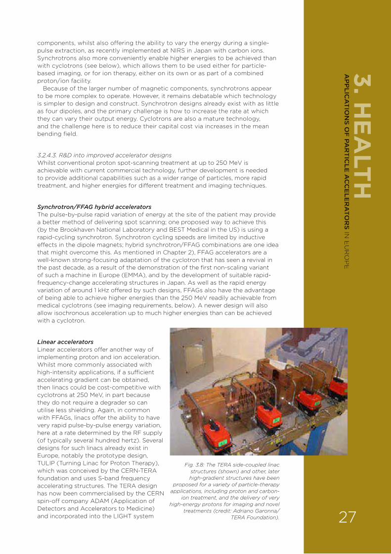
Linear acceleratorsLinear accelerators o¥er another way of implementing proton and ion acceleration. Whilst more commonly associated with high-intensity applications, if a su§cient accelerating gradient can be obtained, then linacs could be cost-competitive with cyclotrons at 250 MeV, in part because they do not require a degrader so can utilise less shielding. Again, in common with FFAGs, linacs o¥er the ability to have very rapid pulse-by-pulse energy variation, here at a rate determined by the RF supply (of typically several hundred hertz). Several designs for such linacs already exist in Europe, notably the prototype design, TULIP (Turning Linac for Proton Therapy), which was conceived by the CERN-TERA foundation and uses S-band frequency accelerating structures. The TERA design has now been commercialised by the CERN spin-o¥ company ADAM (Application of Detectors and Accelerators to Medicine) and incorporated into the LIGHT system
Fig. 3.8: The TERA side-coupled linac structures (shown) and other, later high-gradient structures have been
proposed for a variety of particle-therapy applications, including proton and carbon-
ion treatment, and the delivery of very high-energy protons for imaging and novel
treatments (credit: Adriano Garonna/TERA Foundation).
3. HE
ALTH
27
AP
PLIC
AT
ION
S OF
PAR
TIC
LE A
CC
ELE
RA
TOR
S IN E
UR
OP
E
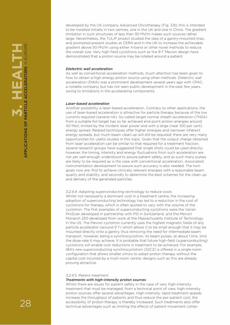
developed by the UK company Advanced Oncotherapy (Fig. 3.8); this is intended to be installed initially in two centres, one in the UK and one in China. The gradient limitation in such structures of less than 30 MV/m makes such sources rather large. Nevertheless, the TULIP project studied the idea of a gantry-mounted linac, and prompted present studies at CERN and in the UK to increase the achievable gradient above 50 MV/m using either X-band or other novel methods to reduce the overall size. Very high-field cyclotrons such as the 9-T Mevion design have demonstrated that a proton source may be rotated around a patient.
Dielectric wall accelerationAs well as conventional acceleration methods, much attention has been given to how to obtain a high-energy proton source using other methods. Dielectric wall acceleration (DWA) was a prominent development several years ago with CPAC, a notable company, but has not seen public development in the past few years, owing to limitations in the accelerating components.
Laser-based accelerationAnother possibility is laser-based acceleration. Contrary to other applications, the use of laser-based acceleration is attractive for particle therapy because of the low currents required (several nA). So-called target normal sheath acceleration (TNSA) from a suitable foil target has so far achieved end-point proton energies around 40 MeV, limited by the incident laser power and with a large (near 100 per cent) energy spread. Related techniques o¥er higher energies and narrower inherent energy spreads, but much beam clean-up will still be required; there are very many opportunities for useful studies in this topic. Given that the output charge obtained from laser acceleration can be similar to that required for a treatment fraction, several research groups have suggested that single shots could be used directly; however, the timing, intensity and energy fluctuations from such acceleration are not yet well-enough understood to assure patient safety, and as such many pulses are likely to be required as is the case with conventional acceleration. Associated instrumentation development to assure such accuracy is also needed. The twin goals now are: first to achieve clinically relevant energies with a reasonable beam quality and stability; and secondly to determine the best schemes for the clean-up and delivery of the generated particles.
3.2.4.4. Adopting superconducting technology to reduce costsWhilst not necessarily a dominant cost in a treatment centre, the increasing adoption of superconducting technology has led to a reduction in the cost of cyclotrons for therapy, which is often quoted to vary with the volume of the cyclotron. The first examples of superconducting cyclotrons were the Varian ProScan developed in partnership with PSI in Switzerland, and the Mevion Monarch 250 developed from work at the Massachusetts Institute of Technology in the US. The Mevion cyclotron currently uses the highest magnetic fields of any particle accelerator (around 9 T) which allows it to be small enough that it may be mounted directly onto a gantry, thus removing the need for intermediate beam transport. However, being a synchrocyclotron, its beam pulses, at about 1 kHz, limit the dose-rate it may achieve. It is probable that future high-field (superconducting) cyclotrons will enable cost reductions in treatment to be achieved. For example, IBA’s new superconducting synchrocyclotron (S2C2) is o¥ered in a single-room configuration that allows smaller clinics to adopt proton therapy without the capital cost incurred by a multi-room centre; designs such as this are already proving attractive.
3.2.4.5. Patient treatment Treatments with high-intensity proton sourcesWhilst there are issues for patient safety in the case of very high-intensity treatment that must be managed, from a technical point of view, high-intensity proton sources o¥er several advantages. High-intensity, rapid treatment speeds increase the throughput of patients and thus reduce the per-patient cost; the accessibility of proton therapy is thereby increased. Such treatments also o¥er technical advantages such as limiting the e¥ects of patient movement (when
3. H
EA
LTH
28
AP
PLI
CA
TIO
NS
OF
PA
RT
ICLE
AC
CE
LER
ATO
RS
IN E
UR
OP
E
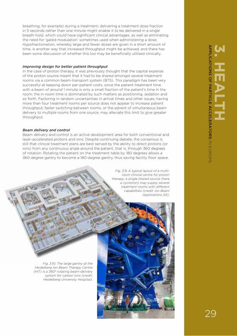
breathing, for example) during a treatment; delivering a treatment dose fraction in 5 seconds rather than one minute might enable it to be delivered in a single breath-hold, which could have significant clinical advantages, as well as eliminating the need for ‘gated modulation’ sometimes used when administering a dose. Hypofractionation, whereby large and fewer doses are given in a short amount of time, is another way that increased throughput might be achieved, and there has been some discussion of whether this too may be beneficially utilised clinically.
Improving design for better patient throughputIn the case of proton therapy, it was previously thought that the capital expense of the proton source meant that it had to be shared amongst several treatment rooms via a common beam-transport system (BTS). This paradigm has been very successful at keeping down per-patient costs, since the patient treatment time with a beam of around 1 minute is only a small fraction of the patient’s time in the room; the in-room time is dominated by such matters as positioning, sedation and so forth. Factoring in random uncertainties in arrival times and other issues, having more than four treatment rooms per source does not appear to increase patient throughput; faster switching between rooms, or the advent of simultaneous beam delivery to multiple rooms from one source, may alleviate this limit to give greater throughput.
Beam delivery and controlBeam delivery and control is an active development area for both conventional and laser-accelerated protons and ions. Despite continuing debate, the consensus is still that clinical treatment plans are best served by the ability to direct protons (or ions) from any continuous angle around the patient, that is, through 360 degrees of rotation. Rotating the patient on the treatment table by 180 degrees allows a 360-degree gantry to become a 180-degree gantry, thus saving facility floor space.
Fig. 3.9: A typical layout of a multi-room clinical centre for proton
therapy; a single shared source (here a cyclotron) may supply several treatment rooms with di�erent
capabilities (credit: Ion Beam Applications SA).
Fig. 3.10: The large gantry at the Heidelberg Ion Beam Therapy Centre
(HIT) is a 360° rotating beam-delivery system for carbon ions (credit:
Heidelberg University Hospital).
3. HE
ALTH
29
AP
PLIC
AT
ION
S OF
PAR
TIC
LE A
CC
ELE
RA
TOR
S IN E
UR
OP
E

Gantry designFixed lines o¥ering only a few treatment angles have been implemented, but have been considered to be less clinically e¥ective as they limit the optimisation of treatment plans. Whilst the first gantry that was implemented bent the beam in more than one plane to reduce the longitudinal extent (the so-called Koehler corkscrew gantry), current gantry designs employ a single bend plane (thus reducing the expense of the magnets), with most gantries employing normal-conducting magnets, and in which transverse scanning of the proton beam is carried out downstream of the final dipole magnet. So-called upstream scanning is employed at PSI for protons and at HIT and NIRS for carbon ions; the principle reason for utilising upstream scanning is to reduce the diameter of the gantry. NIRS
employs superconducting magnets for all of its bends (Fig. 3.11). Lately, there has been much interest in improving gantry design, either to minimise their size, weight and cost, or to provide faster scanning either by increasing the energy acceptance or by improving magnet performance; two workshops have been sponsored by EUCARD2 to support this development.
One notable gantry design is a superconducting system under development by the US company ProNova, which employs a high-field final achromat to reduce the weight to around 25 tonnes and to improve patient access by having a large final throw from dipole to patient. Another example is the design proposed by Brookhaven National Laboratory in New York, which utilises strong-focusing
FFAG magnets to remove the need for field adjustment during energy variation. Similarly, the Lawrence Berkeley National Laboratory (LBNL) in California proposes a superconducting final bend in a Pavlovic-type optics to reduce the gantry size whilst increasing energy acceptance. Finally, CNAO in Italy and others have proposed a Riesenrad (exocentric) gantry for carbon treatment that keeps the heavy magnet rotation on a single axis, and the patient is also moved in front of the rotating magnet.
The large number of designs being explored indicates the degree of innovation that may be possible. Further examples are the incorporation of acceleration within the gantry itself, as implemented by Mevion and proposed by TERA (see above). Currently, scanned-beam treatments typically utilise a layer-by-layer approach, in which the deepest layer is irradiated first; however, this need not necessarily be employed, and changes to the available transverse and longitudinal scanning rates, and beam distributions, may give cause for that approach to be modified.
3.2.4.6. Combined imaging and treatmentImaging using secondary emissions from the proton or ion beamA very important growing element of particle therapy is to employ imaging as part of the treatment process. Imaging via the emission of secondary particles, for example, prompt gamma-ray or positron emission, which are emitted when the proton or ion beam impinges on tissue, is probably the most advanced technique at the moment to determine the particle range in a patient.
Proton tomographyThere is also considerable ongoing development towards proton tomography, which utilises high-energy protons that pass through the patient to form improved density and direct stopping-power representations for treatment planning. Several detector systems, based mainly on semiconductor trackers and calorimeters, are nearing clinical use (for example, those developed by research groups in the US, Italy and the UK), and accelerator sources have been proposed to deliver the
Fig. 3.11: The first superconducting gantry for carbon-ion therapy, installed at NIRS (Japan),
which utilises superconducting, combined-function magnets with fields up to 2.9 T
(credit: Y. Iwata/NIRS).
3. H
EA
LTH
30
AP
PLI
CA
TIO
NS
OF
PA
RT
ICLE
AC
CE
LER
ATO
RS
IN E
UR
OP
E
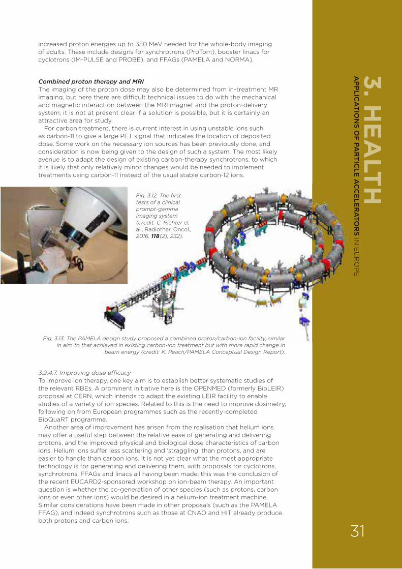
increased proton energies up to 350 MeV needed for the whole-body imaging of adults. These include designs for synchrotrons (ProTom), booster linacs for cyclotrons (IM-PULSE and PROBE), and FFAGs (PAMELA and NORMA).
Combined proton therapy and MRIThe imaging of the proton dose may also be determined from in-treatment MR imaging, but here there are di§cult technical issues to do with the mechanical and magnetic interaction between the MRI magnet and the proton-delivery system; it is not at present clear if a solution is possible, but it is certainly an attractive area for study.
For carbon treatment, there is current interest in using unstable ions such as carbon-11 to give a large PET signal that indicates the location of deposited dose. Some work on the necessary ion sources has been previously done, and consideration is now being given to the design of such a system. The most likely avenue is to adapt the design of existing carbon-therapy synchrotrons, to which it is likely that only relatively minor changes would be needed to implement treatments using carbon-11 instead of the usual stable carbon-12 ions.
3.2.4.7. Improving dose e°cacyTo improve ion therapy, one key aim is to establish better systematic studies of the relevant RBEs. A prominent initiative here is the OPENMED (formerly BioLEIR) proposal at CERN, which intends to adapt the existing LEIR facility to enable studies of a variety of ion species. Related to this is the need to improve dosimetry, following on from European programmes such as the recently-completed BioQuaRT programme.
Another area of improvement has arisen from the realisation that helium ions may o¥er a useful step between the relative ease of generating and delivering protons, and the improved physical and biological dose characteristics of carbon ions. Helium ions su¥er less scattering and ‘straggling’ than protons, and are easier to handle than carbon ions. It is not yet clear what the most appropriate technology is for generating and delivering them, with proposals for cyclotrons, synchrotrons, FFAGs and linacs all having been made; this was the conclusion of the recent EUCARD2-sponsored workshop on ion-beam therapy. An important question is whether the co-generation of other species (such as protons, carbon ions or even other ions) would be desired in a helium-ion treatment machine. Similar considerations have been made in other proposals (such as the PAMELA FFAG), and indeed synchrotrons such as those at CNAO and HIT already produce both protons and carbon ions.
Fig. 3.12: The first tests of a clinical prompt-gamma imaging system (credit: C. Richter et al., Radiother. Oncol., 2016, 118(2), 232).
Fig. 3.13: The PAMELA design study proposed a combined proton/carbon-ion facility, similar in aim to that achieved in existing carbon-ion treatment but with more rapid change in
beam energy (credit: K. Peach/PAMELA Conceptual Design Report).
3. HE
ALTH
31
AP
PLIC
AT
ION
S OF
PAR
TIC
LE A
CC
ELE
RA
TOR
S IN E
UR
OP
E

3.2.4.8. Other particle therapiesBoron-neutron capture therapy (BCNT)The main challenges for BNCT are:
› the accurate shaping of the incident neutron field such that the boron capture is optimised without undue neutron dose to the patient;
› the e§cient taking-up of the administered boron-containing agent by the tumour cells;
› the creation of neutrons with su§cient intensity via a suitable nuclear reaction and target. Typically, low-energy reactions involving accelerated proton beams impinging on a lithium or beryllium target are used.
Electron therapyFor very high-energy electron therapy (VHEET), what is needed is the demonstration of a suitable high-gradient accelerating system – whether conventional, such as X-band, or not – and the development of novel concepts that take advantage of the charged electrons to improve the beam delivery (focusing schemes, scanning, and so forth).
Use of exotic particlesThere is also some scope to study more exotic species, but the priority should be towards how to translate such work into clinical use in an a¥ordable manner, with a good understanding of the biological mechanisms of their action, and to pursue improvements that are driven by clinical demand.
3.2.5. GENERIC CHALLENGES The need for advances in superconducting magnet technology An over-arching technology development common to all particle therapies is the advance in superconducting magnet systems. In particular, the ability to achieve high fields up to about 4 T – in magnets that may be readily varied in field strength whilst also being rotated – is strongly desired in many of the applications described above.
Improved computer modelling, control and monitoring systemsThere is need for improved modelling support through the use of large-scale simulation, principally of particle transport through patients. This is likely to be best achieved through development of the gold-standard GEANT4 code, paying attention to improvements in the validation of its nuclear physics models, particularly of protons and carbon ions over the 1-to-400 MeV-energy range, and improvements that make large-scale calculation more e§cient. The complexity of the beam-delivery systems (scanning, energy changes, special patterns, and so on), together with the need for high doses (hypofractionation), high dose rates (shorter delivery times, and maybe di¥erent biological e¥ects), the management of organ movements and the delivery of adaptive therapy (for example, to adapt to changes in the patient anatomy) call for the development of new control systems and monitoring devices that optimise the patient workflow and provide a warranty for the quality control of every treatment.
More research/industry collaborationThe EUCARD-2 programme has made some significant strides in bringing together researchers and industry in common events. However, more needs to be done.
There also remains a gap between the initial technology development and the eventual clinical licensing of new methods, and commercial providers have always had a key role here in bringing new products to market. The implementation in routine clinical operation of spot scanning is an important case study in which a national laboratory (PSI) initiated work to demonstrate the advantages of the method, which then drove clinical demand leading to the provision of such methods in commercial products. It is likely that prompt-gamma imaging and proton tomography, mentioned above, will be adopted in a similar manner.
3. H
EA
LTH
32
AP
PLI
CA
TIO
NS
OF
PA
RT
ICLE
AC
CE
LER
ATO
RS
IN E
UR
OP
E

A counter-example is carbon-ion therapy; the clinical centres that o¥ered this treatment found it di§cult to obtain reimbursement to match their costs, leading to a smaller commercial o¥ering today than was the case only a few years ago. This is part of a wider issue of trying to achieve lower costs in particle therapy, which – more than technology improvements – is the primary driver for most commercial providers today.
Particle therapy must rightly compete with X-ray therapy, which is currently the cheaper method, and so particle therapy must demonstrate improved outcomes. National and EU policy on indications and reimbursements for particle-therapy treatments are an important issue that must be better understood to determine the right developments in this field. National and EU networks that improve the links between clinical and technical developers are key to achieving this.
3.2.6. PRIORITY AREAS FOR R&D IN RADIOTHERAPY
› Cost-reduction methods for X-ray therapy machines, for example, in the linac structures, in the delivery system and in the adaptive solutions;
› The operational integration of particle-therapy systems with conventional X-ray systems to achieve the optimal treatment for patients in terms of survival rates, reduction in side-e¥ects and cost;
› The development of new combined imaging methods and fast, lightly-intercepting instrumentation for accurate delivery;
› The development of lower-cost particle sources from 250 to 350 MeV, including high-field cyclotrons, synchrocyclotrons, very compact synchrotrons, high-gradient linacs and novel architectures such as laser-based acceleration with the appropriate beam properties;
› The development of solutions to allow depth-dose imaging, including improved diagnostic methods such as prompt-gamma imaging and proton tomography, and the development of particle sources supporting such imaging;
› The development of systematic studies of ion RBEs and radiobiology to improve clinical modelling;
› The development of lower-cost, combined treatment machines capable of delivering the appropriate ion combinations resulting from radiobiological studies which could include both carbon ions and helium ions – a facility design is required;
› The development of solutions for secondary-particle imaging for ions, particularly 11C/PET;
› The design and implementation of improved lighter gantry systems for proton and ion delivery, utilising superconducting magnets and/or FFAG designs;
› The demonstration of high-energy electron therapy and the design of a system to optimally use it;
› The demonstration of high-flux BNCT using improved production targets;
› The consideration of co-use of facilities to achieve these and other applications, for example, combining isotope production with RBE studies or isotope production with proton therapy.
› Finally, it is crucial to emphasise the importance of carrying out multidisciplinary research in radiobiology, as one of the bases of progress in radiotherapy.
3. HE
ALTH
33
AP
PLIC
AT
ION
S OF
PAR
TIC
LE A
CC
ELE
RA
TOR
S IN E
UR
OP
E

3.2.7. IMPACT ON INDUSTRY AND EDUCATION3.2.7.2. IndustryThe equipment for radiation therapy represents an annual market of nearly 6 billion dollars with a growth rate close to 7 per cent. While standardisation is essential, there is also a continuous improvement through updates, upgrades and big technological changes that needs support from basic and applied research. New approaches not only improve the results (better tumour control, fewer complications), but also may open up new indications. In particular:
› X-ray radiotherapy: a better engagement in driving improvements to existing equipment designs may deliver cost savings (for example, in RF-structure designs) and thereby increased access to treatment, particularly in emerging economies;
› Proton therapy: new technologies or imaging systems could enable new products to be o¥ered; di¥erent technologies provide distinct IP that allow companies to enter the market;
› Ion therapy: lower-cost designs may allow ion therapy to be adopted commercially in competition with proton therapy; systematic studies of RBE and related work can justify the greater cost of such treatment, leading to a commercial space for products;
› VHEET: the demonstration of a new treatment method would first be in a clinic, then perhaps adopted more widely; it would need clinical justification in terms of improved dose at the equivalent cost to X-ray treatment;
› Component development: the development of technologies such as fast-ramping superconducting magnets and high-gradient X-band cavities provide new solutions for other research areas and for companies providing these components.
3.2.7.3. EducationThe better tying-together of technological and clinical knowledge can in part be achieved through the development of sta¥ skilled in both areas. For example, the EU OMA programme is funding 15 early-stage researchers who will develop skills across these discipline boundaries. The outcome will be a pool of experienced sta¥ who can assist in the development and operation of clinical facilities around Europe (and elsewhere), and who may enter industry to improve their product o¥erings. There is ample evidence of this occurring at many national laboratories and European research institutes. For example, in previous EU networks DITANET, OPAC and LA3NET, a good percentage of the trained researchers went on to industrial/commercial posts. Networking activities with EUCARD2 have also attracted many of the main companies involved in radiotherapy accelerators, and several collaborations have been initiated between companies and research institutes as a direct result of EUCARD2 network events. One example is the recent collaboration between Varian, LBNL and PSI on the development of a superconducting-gantry design for proton-beam delivery.
3.3. RADIONUCLIDES3.3.1. STATE OF THE ART Radionuclides (radioactive isotopes) have been employed in medicine ever since radioactivity was discovered. Produced in an accelerator or a nuclear reactor, the variety of radionuclides that can be used for in-vivo imaging and therapy suited to treating specific diseases is increasing. As reactors become an increasingly less reliable source of radioisotopes, a clear strategy for the development of dedicated, cost-e¥ective and versatile accelerators is needed.
3. H
EA
LTH
34
AP
PLI
CA
TIO
NS
OF
PA
RT
ICLE
AC
CE
LER
ATO
RS
IN E
UR
OP
E

Radionuclides have two main uses: imaging and cancer therapy.
ImagingThe radionuclide is delivered to the region of the patient to be imaged using a pharmaceutical that has been labelled with a specific radionuclide. The decay products of the radionuclide are detected and used to determine the location of
each decay event, from which an image can be reconstructed.
The most commonly used imaging technique is single-photon emission computed tomography (SPECT), in which the radionuclide decays via the emission of a single gamma-ray photon, which is then detected.
The second technique is positron emission tomography (PET), in which the decay results in the emission of a positron (positively charged electron). This then annihilates with a nearby (negative) electron to release two gamma-rays, which are detected. PET is e¥ective at imaging tumours and metastases, and mapping the function of major organs like the brain, where it can visualise physical changes associated with neurological disorders. Although PET is currently not as widely used as SPECT, the emission of two photons means that it tends to have a better image resolution.
It should be noted that SPECT and PET are very good at identifying the location of tumours, for example, but much worse at showing the surroundings. This is because the radio-pharmaceuticals used are designed to deliver them to the highly active tumour cells. To overcome this problem, SPECT and PET are now usually done in combination with another imaging technique such as CT or MRI. These show the surroundings much better, so giving a superior, combined picture of the tumour.
Cancer therapy In this treatment, radionuclides used are those that decay into highly-ionising particles – alpha particles (helium nuclei) or high-energy beta particles (electrons) – which are capable of killing cancer cells. They are attached to chemical compounds that are preferentially taken up by cancerous tissue. A promising new therapy involves binding the radionuclide to an antibody that specifically targets a tumour cell (radio-immunotherapy).
This type of therapy has huge potential, but is not being fully exploited currently because most of the radionuclides used are produced in nuclear reactors, and the supply can be somewhat erratic. Furthermore, although some of the alpha-decaying radionuclides with the most potential can be created by accelerators, they require beams of alpha and other accelerated particles for their production. Most of the commercial accelerators are unable to provide these beams.
Fig. 3.14: A combined PET/MRI image revealing cancer metastases (credit: Siemens/TUM/LMU).
3. HE
ALTH
35
AP
PLIC
AT
ION
S OF
PAR
TIC
LE A
CC
ELE
RA
TOR
S IN E
UR
OP
E
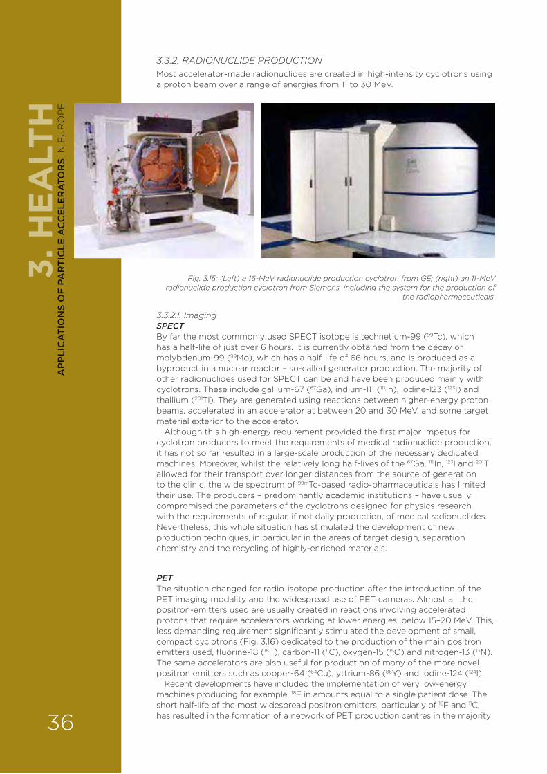
3.3.2. RADIONUCLIDE PRODUCTIONMost accelerator-made radionuclides are created in high-intensity cyclotrons using a proton beam over a range of energies from 11 to 30 MeV.
3.3.2.1. ImagingSPECTBy far the most commonly used SPECT isotope is technetium-99 (99Tc), which has a half-life of just over 6 hours. It is currently obtained from the decay of molybdenum-99 (99Mo), which has a half-life of 66 hours, and is produced as a byproduct in a nuclear reactor – so-called generator production. The majority of other radionuclides used for SPECT can be and have been produced mainly with cyclotrons. These include gallium-67 (67Ga), indium-111 (111
1In), iodine-123 (123I) and thallium (201Tl). They are generated using reactions between higher-energy proton beams, accelerated in an accelerator at between 20 and 30 MeV, and some target material exterior to the accelerator.
Although this high-energy requirement provided the first major impetus for cyclotron producers to meet the requirements of medical radionuclide production, it has not so far resulted in a large-scale production of the necessary dedicated machines. Moreover, whilst the relatively long half-lives of the 67Ga, 111
1In, 123I and 201Tl allowed for their transport over longer distances from the source of generation to the clinic, the wide spectrum of 99mTc-based radio-pharmaceuticals has limited their use. The producers – predominantly academic institutions – have usually compromised the parameters of the cyclotrons designed for physics research with the requirements of regular, if not daily production, of medical radionuclides. Nevertheless, this whole situation has stimulated the development of new production techniques, in particular in the areas of target design, separation chemistry and the recycling of highly-enriched materials.
PETThe situation changed for radio-isotope production after the introduction of the PET imaging modality and the widespread use of PET cameras. Almost all the positron-emitters used are usually created in reactions involving accelerated protons that require accelerators working at lower energies, below 15–20 MeV. This, less demanding requirement significantly stimulated the development of small, compact cyclotrons (Fig. 3.16) dedicated to the production of the main positron emitters used, fluorine-18 (18F), carbon-11 (11C), oxygen-15 (15O) and nitrogen-13 (13N). The same accelerators are also useful for production of many of the more novel positron emitters such as copper-64 (64Cu), yttrium-86 (86Y) and iodine-124 (124I).
Recent developments have included the implementation of very low-energy machines producing for example, 18F in amounts equal to a single patient dose. The short half-life of the most widespread positron emitters, particularly of 18F and 11C, has resulted in the formation of a network of PET production centres in the majority
Fig. 3.15: (Left) a 16-MeV radionuclide production cyclotron from GE; (right) an 11-MeV radionuclide production cyclotron from Siemens, including the system for the production of
the radiopharmaceuticals.
3. H
EA
LTH
36
AP
PLI
CA
TIO
NS
OF
PA
RT
ICLE
AC
CE
LER
ATO
RS
IN E
UR
OP
E
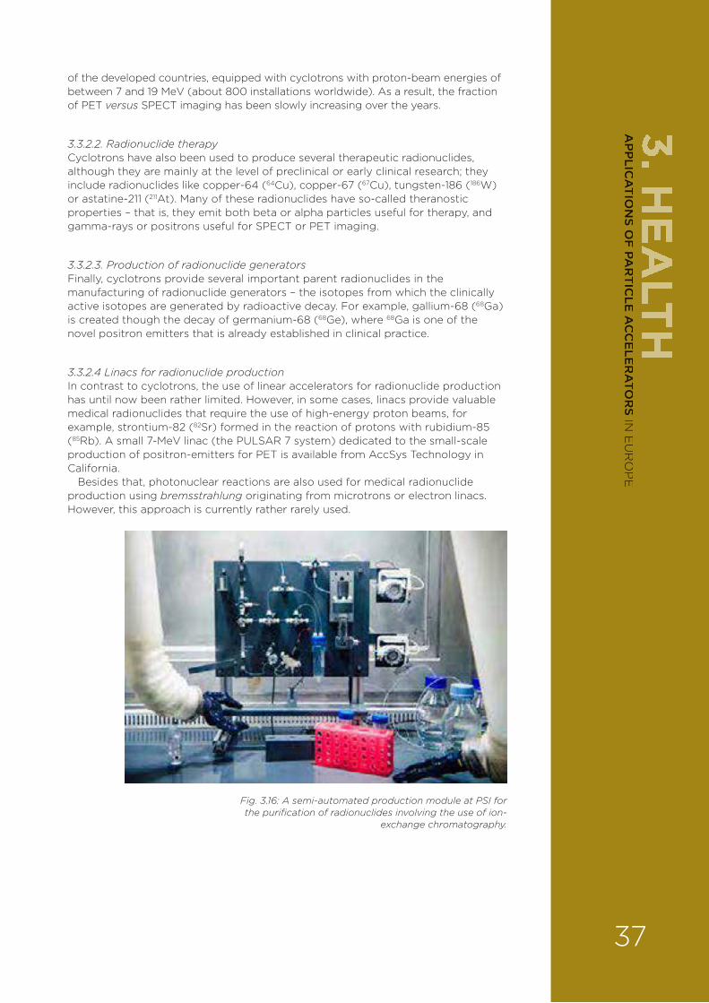
of the developed countries, equipped with cyclotrons with proton-beam energies of between 7 and 19 MeV (about 800 installations worldwide). As a result, the fraction of PET versus SPECT imaging has been slowly increasing over the years.
3.3.2.2. Radionuclide therapyCyclotrons have also been used to produce several therapeutic radionuclides, although they are mainly at the level of preclinical or early clinical research; they include radionuclides like copper-64 (64Cu), copper-67 (67Cu), tungsten-186 (186W) or astatine-211 (211At). Many of these radionuclides have so-called theranostic properties – that is, they emit both beta or alpha particles useful for therapy, and gamma-rays or positrons useful for SPECT or PET imaging.
3.3.2.3. Production of radionuclide generatorsFinally, cyclotrons provide several important parent radionuclides in the manufacturing of radionuclide generators – the isotopes from which the clinically active isotopes are generated by radioactive decay. For example, gallium-68 (68Ga) is created though the decay of germanium-68 (68Ge), where 68Ga is one of the novel positron emitters that is already established in clinical practice.
3.3.2.4 Linacs for radionuclide productionIn contrast to cyclotrons, the use of linear accelerators for radionuclide production has until now been rather limited. However, in some cases, linacs provide valuable medical radionuclides that require the use of high-energy proton beams, for example, strontium-82 (82Sr) formed in the reaction of protons with rubidium-85 (85Rb). A small 7-MeV linac (the PULSAR 7 system) dedicated to the small-scale production of positron-emitters for PET is available from AccSys Technology in California.
Besides that, photonuclear reactions are also used for medical radionuclide production using bremsstrahlung originating from microtrons or electron linacs. However, this approach is currently rather rarely used.
Fig. 3.16: A semi-automated production module at PSI for the purification of radionuclides involving the use of ion-
exchange chromatography.
3. HE
ALTH
37
AP
PLIC
AT
ION
S OF
PAR
TIC
LE A
CC
ELE
RA
TOR
S IN E
UR
OP
E
3.3.3. RESEARCH CHALLENGESThe existing network of medical cyclotrons, particularly dedicated machines for positron emitters, naturally attracts the attention of researchers in order to maximise their use in providing an increasingly wider spectrum of novel medical radionuclides. For radionuclides produced via simple reactions, the main issues to be addressed are the following:
› The availability and price of the target material (particularly if an enriched isotope is required);
› The yield and achievable radionuclide purity;
› The physico-chemical properties of the target layer (thermal conductivity, melting point, feasibility of the target layer manufacturing);
› E§cient separation chemistry and suitable labelling chemistry;
› The availability of e§cient recycling of the enriched target matrix, if necessary;
› Automation and the related decrease of personnel radiation burden.
3.3.3.1. Accelerator requirementsFor the production of novel and more sophisticated radionuclides, the economics, or even the technical feasibility of a particular radionuclide production, is dictated by two parameters closely related to cyclotron technology – the maximum available beam energy and the maximum available current. In some cases, the availability of beams for particles other than protons, like deuterons or alpha particles, is also a key factor in production of a particular radionuclide (for example, 211At can be e§ciently obtained only with use of an alpha-particle beam).
The modern and e§cient production of medical radionuclides thus requires accelerators that are:
› versatile – able to be tuned over a wide energy range to high energies (30 MeV) to produce a wider range of isotopes;
› relatively inexpensive to acquire and cost-e¥ective to run;
› capable of running at high currents to increase radionuclide yields.
Availability of a wide range of energies We can currently observe a trend to bridge the gap between traditional PET-dedicated machines and cyclotrons with a proton-beam energy of up to 30 MeV, by designing and manufacturing relatively cheap cyclotrons with energies between 19 and 30 MeV. Recently, the Canadian company ACSI released two new cyclotrons working at 24 and 28MeV respectively, TR24 and TR28, which provide a maximum beam current up to 1 mA, thanks to external ion-source technology (an ion source creates the charged particle beam). They allow reactor-generated isotopes such as 99mTc to be produced with a cyclotron.
Cost-reduction through more compact acceleratorsSuper-compact solutions minimising the cyclotron dimensions via the use of superconducting magnets represent another technical approach to address these requirements, although their implementation into the large-scale radionuclide production has not yet been realised.
Increasing beam current to maximise yield Increasing the beam current brings technical challenges, mainly the e§cient cooling of the given target matrix. The appropriate design and testing of the whole target system is an inevitable part in the development of a sustainable technology for the production of a new radionuclide. The manufacture of a target matrix must allow for well-reproducible layers, and be also compatible with the subsequent separation of the radionuclide and e§cient recycling of the enriched material, if required.
3. H
EA
LTH
38
AP
PLI
CA
TIO
NS
OF
PA
RT
ICLE
AC
CE
LER
ATO
RS
IN E
UR
OP
E
Obtaining reliable data for the calculation of yields and the achievable radionuclide purity is also an important part of the process, because the current predictive nuclear-reaction model codes (TALYS, EMPIRE, ALICE) may still significantly di¥er from the real cross-sections (probabilities) of a reaction. Experimentally obtained excitation functions are therefore required in order to get sound values. These measurements are performed on cyclotrons as well as linacs, although the requirements for such experiments di¥er from the large-scale radionuclide production (low beam currents, precise beam energies with minimum dispersion).
3.3.3.2. Challenges in medical radionuclide production using acceleratorsThere are two areas of interest:
› R&D on the production of novel diagnostic or therapeutic radionuclides;
› Testing alternative production routes of established medical radionuclides.
New radionuclidesWe can describe the first area as the exploration of a large pool of radionuclides that are potentially interesting for molecular imaging or targeted radionuclide therapy. These start with radionuclides that are already entering clinical practice – for example, copper-64 (64Cu), iodine-124 (124I), radium-223 (223Ra), actinium-225 (225Ac) – and ending with less advanced or recently proposed candidates – for example, scandium-44 (444Sc), titanium-45 (45Ti), scandium-47 (47Sc), manganese-52 (52Mn), iron-52 (52Fe), copper-61 (61Cu), cobalt-55 (55Co), copper-67 (67Cu), rhenium-186 (186Re), astatine-211 (211At) and uranium-230 (230U). Many of these radionuclides may be easily produced on a dedicated medical cyclotron typically used for fluorine-18 production, but the appropriate targetry, target-material, processing/separation and R&D of pharmaceutical potential carriers are not yet at hand or not entirely completed. Some of them (for example, 52Fe) require unusually high-beam energies or an unusual beam particles such as alpha particles or even helium-3 ions (3He).
Similar enlightenment is required in the field of novel therapeutic radionuclides, namely alpha-emitters. The alpha-emitters have excellent properties for the therapy of certain sorts of cancer, but the development of appropriate carriers is very demanding. Recent successes in the clinical use of the alpha-emitter, radium-223 (223Ra) for treating metastatic prostate cancer at Heidelberg, and the large-scale clinical trials at Warsaw on very short-lived bismuth-213 (213Bi) – generated by the decay of actinium-225 (225Ac) – for the radio-immunotherapy of leukaemia, are good arguments for further work in this direction.
Novel accelerator productionThe second field is focused on a few radionuclides already well established in the clinical practice. Top of this list is R&D on alternative production routes for 99Mo and 99mTc. The recent shortage crisis in the conventional 99Mo production in nuclear reactors (2009–2010) revealed the vulnerability, high centralisation and hidden subsidies in the production chain of 99Mo/99mTc generators. In this context, the direct production in accelerators of 99mTc by bombarding 100Mo with protons in a cyclotron, together with the production of the 99Mo generator via the photo-fission of uranium-238 (238U) or the neutron spallation of molybdenum-100 (100Mo) are being studied; they seem to be both technically feasible and economically sustainable. A particular advantage is that the accelerator production method avoids the creation of a high amount of the long-lived radioactive waste, inevitably generated through fission reactions in a reactor.
Another example of this alternative approach is the direct production of 68Ga in cyclotrons from the reaction of protons with zinc-68 (68Zn) – instead of using the very expensive 68Ge/68Ga generator method mentioned earlier. The short half-life and relatively high yields from this reaction enable it to be made on the existing network of dedicated medical cyclotrons in amounts that are comparable, or exceed, those available from the elution of the commercial 68Ge/68Ga generators through separation chemistry.
3. HE
ALTH
39
AP
PLIC
AT
ION
S OF
PAR
TIC
LE A
CC
ELE
RA
TOR
S IN E
UR
OP
E

3.3.4. POLITICAL AND SOCIAL CHALLENGESEnsuring an adequate supply of medical isotopes in EuropeEurope, so far, has been rather relaxed regarding the much-publicised 99Mo/99mTc production crisis – in contrast to Canada. Up till now, it has relied on the extended capacity of its current research nuclear reactors. However, we should keep in mind that Europe may soon have to compete with the US for its own 99Mo production – once the current biggest producer of this isotope, the NRU reactor in Chalk River, Canada, is finally decommissioned. It would therefore be provident to ensure that there is a realistic and reliable alternative to hand. The existing network of the medical cyclotrons operated in the established PET centres form a natural basis for a decentralised solution complementary to the reactor-produced 99Mo/99mTc generators. The same network would also be a tool for the independent production of 68Ga at a local level.
Public perception of the clinical use of radioactive isotopesIn many European countries, the public tends to have a negative perception of the use radioactive emitters, and there has been a tendency to replace radio-medical diagnostic methods, where possible, with those that do not use radioactivity. The clear benefits of radio-medicine versus the relatively low radiation burden received by the body is often poorly understood by the layperson, and there is generally little appreciation of the extraordinary role that accelerators play in advanced medical treatments. While there is occasional media attention given to a specific procedure, together with a heart-warming human story of a successful clinical outcome, it is vitally important that our decision-makers appreciate the wider picture and the potential in supporting the relevant accelerator research programmes.
3.3.5. PRIORITY AREAS FOR R&D IN MEDICAL RADIONUCLIDE PRODUCTIONThere are two distinct areas:
› The first is directly related to the accelerators themselves. Providing small, compact machines with low acquisition and operational costs is a challenge for the designers and producers of cyclotrons, FFAGs and linacs. All directions of development seem to be open.
› The second area covers targetry and the target chemistry of novel medical radionuclides (like copper and scandium radionuclides) and/or alternative accelerator-based technology for the established medical radionuclides (99mTc and 68Ga).
3.3.6. IMPACT ON INDUSTRY AND EDUCATIONThis R&D can be performed only via a close and e§cient collaboration of research institutes with industrial partners. Some research can be also commercialised by the research institutes themselves, if they have at hand suitable vehicles such as spin-o¥ companies. The key parameter is, of course, funding and the appropriate choice of topics.
We expect there to be a major impact on the cyclotron and linear accelerator producers and companies interested in the first phases of the radio-pharmaceuticals R&D and production.
New approaches will a¥ect both students of applied nuclear physics and chemistry as well as nuclear engineering. This is a typical example of an interdisciplinary R&D – and also involves radio-pharmacists, and indirectly nuclear physicians and experts in molecular imaging and targeted radionuclide therapy.
3. H
EA
LTH
40
AP
PLI
CA
TIO
NS
OF
PA
RT
ICLE
AC
CE
LER
ATO
RS
IN E
UR
OP
E

3.4. KEY RECOMMENDATIONS IN FUNDING FOR APPLICATIONS OF PARTICLE ACCELERATORS TO HEALTH
RadiotherapiesThe key recommendations for funding are:
› Further research in medical physics and the promotion of technological development in the field of radiotherapy using a multidisciplinary approach, including the use of biological information (genetic and molecular biology-based data) and immunological protocols, clinically oriented towards personalised medicine, with the participation of clinical centres, academics, laboratories and industry (including physicians, physicists, biologists, engineers and paramedical sta©).
› Strong links and cooperation between academics, industry, national and international research organisations such as CERN, public and private hospitals, universities, with the widespread dissemination of results to the community;
› A design study for a future multi-particle therapy facility, possibly including helium-ion treatment and/or secondary imaging as its primary goals;
› Clinical studies to demonstrate the benefits of new therapies;
› The establishment of systematic RBE experiments in Europe, including in-vivo animal studies;
› The study of solutions for ion secondary-particle imaging and other dose-delivery instrumentation;
› A programme of development for high-gradient ion acceleration;
› Support for the development of rotatable superconducting magnet systems.
› Studies to reduce significantly both the initial investment and the functional costs of radiotherapy systems.
Radionuclide production › The investigation of alternative mechanisms for 99Mo and 99mTc production
in Europe.
› The further development of compact sources for PET radionuclide production directly in hospital, in particular for the use of the shorter half-life isotopes.
› The study of novel radionuclides for therapy in particular, but also for imaging.
› The development of compact, high-current accelerators with the ability to accelerate and extract di©erent types of particle for the production of radionuclides for therapy and imaging.
3. HE
ALTH
41
AP
PLIC
AT
ION
S OF
PAR
TIC
LE A
CC
ELE
RA
TOR
S IN E
UR
OP
E

Massimo Chiari, INFN, Florence, Italy.
Andrzei Chimielewski, Institute of the
Institute of Nuclear Chemistry and
Technology, Warsaw, Poland.
Frank-Holm Roegner, FEP – Fraunhofer
Institute for Organic Electronics, Electron
Beam and Plasma Technology, Dresden,
Germany.
Further contributions from
Chris Jeynes, University of Surrey Ion Beam Centre,
Guildford, UK, and
Franco Lucarelli, University of Florence
and INFN, Florence Italy.
PARTICLE BEAMS PRODUCED USING ACCELERATOR TECHNOLOGY PLAY A SIGNIFICANT ROLE IN BOTH THE ANALYSIS AND IN THE MODIFICATION OF SURFACES ACROSS A VERY WIDE RANGE OF FIELDS, FROM MANUFACTURING AND PROCESSING TO ENVIRONMENTAL PROTECTION AND CONSERVATION. THEY OFFER A SELECTIVE LEVEL OF PRECISION AND SENSITIVITY NOT ALWAYS AVAILABLE WITH, SAY, CHEMICAL TECHNIQUES, AND ARE OFTEN NON-INVASIVE AND NON-DESTRUCTIVE. Massimo Chiari, Andrzei Chimielewski and Frank-Holm Roegner
4.I. INTRODUCTIONTwo types of particle beams have been employed across a range of industrial applications for many years:
› electron beams (e-beams);
› ion beams.
E-beams can be separated into two energy regions: very low energy (less than 330 keV) and low energy (330 keV to 10 MeV). Very low-energy e-beams are used largely in surface treatments and processing, while low-energy e-beams, being more penetrating, can e¥ect changes in the bulk material. Ion beams in the keV- and MeV-energy ranges (up to 70 MeV) have also been routinely used for decades to study and modify the surface composition of materials, particularly in relation to electronic materials and advanced nano-structures, composites and thin films, as well as the environment and cultural artefacts.
4.2. VERY LOW-ENERGY E-BEAMS4.2.1 BACKGROUND AND STATE OF THE ARTVery low-energy e-beam accelerators have been used in industry and research since the 1950s, and now play an important role in a number of areas. They are already having a significant economic impact but, until recently, the expansion in their use has been held back by the size and cost of the equipment. However, during the past 6 years, compact low-cost, low-energy e-beam accelerators have become available as industrialised products. We are now at the beginning of an ‘e-beam renaissance’. Within the next 5 to 7 years, more very low-energy e-beam accelerators will be installed than during their entire history of more than 50 years.
4.2.1.1. How very low-energy e-beams are generatedAn e-beam is directed particle radiation. If the potential for acceleration is between 5 kV and 300 kV, then the e-beam is referred to as very low energy. The speed reached by the electrons depends on the acceleration voltage, and is in the range of (1 – 2.3) x 108 metres per second; the
4. I
ND
UST
RY
4. ACCELERATORS AND INDUSTRY
Fig. 4.1: The principle of electron-beam generation and direction for focused beam
applications under vacuum conditions.42
AP
PLI
CA
TIO
NS
OF
PA
RT
ICLE
AC
CE
LER
ATO
RS
IN E
UR
OP
E

maximum value corresponds to 78 per cent of the speed of light (3 x 10⁸ metres per second).
A very low-energy e-beam accelerator used for industrial applications is mostly called an EB-gun, EB-generator or e-beam lamp. The main principle is simple (Fig. 4.1). Inside a vacuum chamber (typically evacuated down to 10-5 to 10-7 mbar), a cathode produces free electrons. These electrons are accelerated under vacuum by an electrostatic force and directed towards a workpiece. Depending on the application, in some cases the path of the electrons is influenced to form a focused beam, and the beam is sometimes statically or dynamically deflected.
4.2.1.2. How very low-energy e-beams interact with matterWhen the accelerated electrons interact with matter, they can excite the atomic electrons and also ionise them (knock out electrons). These interactions lead to important e¥ects:
› the emission of X-rays, and the emission of backscattered, secondary and Auger electrons (electrons emitted from the inner shells of atoms);
› the breaking of molecular bonds;
› heating up.
To achieve these e¥ects, very low-energy e-beams are used in one of two configurations:
› As an expanded electron ‘shower’ at the upper level of the energy range (≥80 keV), but low power density (in the range of 10 W/cm2) to change a material’s chemistry under atmospheric conditions, and with virtually no temperature rise involved.
› As a focused beam with a very high power density up to 108 W/cm2, but lower level of the energy range (≤175 keV), under vacuum conditions to heat up a material.
The following technologically useful operations can then be carried out:
Detection This includes all analytical methods using electrons or X-rays (such as scanning electron microscopy, transmission electron microscopy, Auger electron spectroscopy, X-ray photoelectron spectroscopy and computer-aided tomography).
Cutting, linking and pasting at the molecular level These changes are non-thermal and underpin the chemical modification of organic materials such as monomers, oligomers and polymers, as well as biological materials. The electrons break molecular bonds – and, more specifically (and of much interest to chemists), they create radicals (molecules with unpaired electrons, which make them extremely chemically reactive). The molecular bonds may just stay permanently broken (cutting), and so result in the scission of polymer chains and the degradation of a material. In some cases, however, the radicals that are generated on one section of the polymer chain may react with another part of the chain, causing cross-linking. In other cases, the radicals may bind with active sites on another, chemically di¥erent molecule. This allows two substances to bond together that otherwise would not, and is the e¥ect behind e-grafting, reactive compounding, laminating, and coating. In another e¥ect called curing, a polymerisation chain reaction is kicked-o¥ by the incoming electrons. The target material, such as an ink or a coating, starts o¥ as a liquid or semi-viscous paste. The electrons set o¥ reactions in which the pigment molecules bond with each other and with other ingredients in the ink. Tens of milliseconds later, the material is completely solid. This is sometimes called e-beam drying or e-beam hardening.
Heating This covers thermal applications in which the accelerated electrons heat up materials globally or locally (melting, evaporation, welding, joining, drilling, hardening, di¥usion, sintering).
4. IN
DU
STRY
43
AP
PLIC
AT
ION
S OF
PAR
TIC
LE A
CC
ELE
RA
TOR
S IN E
UR
OP
E
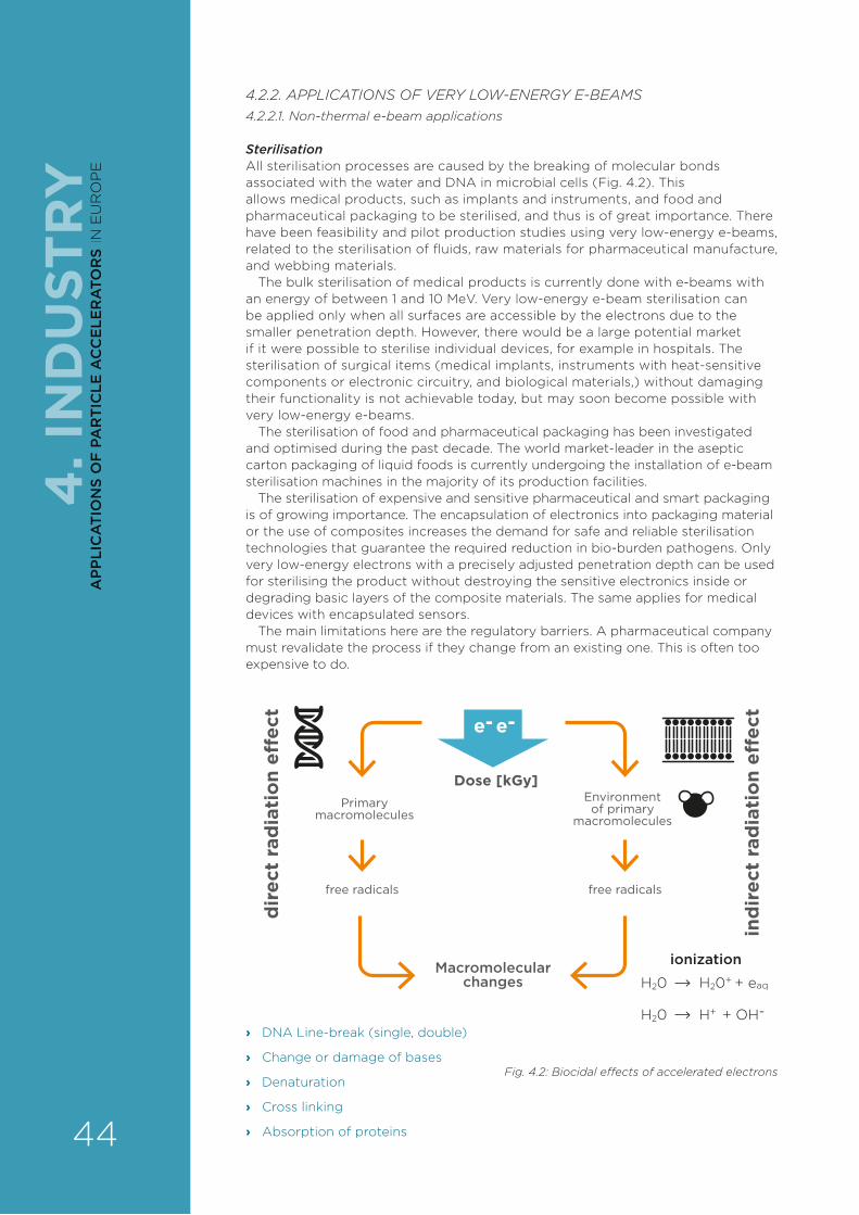
e-
dir
ect
rad
iati
on
e�ec
t
Dose [kGy]
ind
irec
t ra
dia
tio
n e�
ect
Primarymacromolecules
Macromolecularchanges
ionization
Environmentof primary
macromolecules
free radicalsfree radicals
e-
H20 + eaqH20+
H20 + OH-H+
4.2.2. APPLICATIONS OF VERY LOW-ENERGY E-BEAMS4.2.2.1. Non-thermal e-beam applications
SterilisationAll sterilisation processes are caused by the breaking of molecular bonds associated with the water and DNA in microbial cells (Fig. 4.2). This allows medical products, such as implants and instruments, and food and pharmaceutical packaging to be sterilised, and thus is of great importance. There have been feasibility and pilot production studies using very low-energy e-beams, related to the sterilisation of fluids, raw materials for pharmaceutical manufacture, and webbing materials.
The bulk sterilisation of medical products is currently done with e-beams with an energy of between 1 and 10 MeV. Very low-energy e-beam sterilisation can be applied only when all surfaces are accessible by the electrons due to the smaller penetration depth. However, there would be a large potential market if it were possible to sterilise individual devices, for example in hospitals. The sterilisation of surgical items (medical implants, instruments with heat-sensitive components or electronic circuitry, and biological materials,) without damaging their functionality is not achievable today, but may soon become possible with very low-energy e-beams.
The sterilisation of food and pharmaceutical packaging has been investigated and optimised during the past decade. The world market-leader in the aseptic carton packaging of liquid foods is currently undergoing the installation of e-beam sterilisation machines in the majority of its production facilities.
The sterilisation of expensive and sensitive pharmaceutical and smart packaging is of growing importance. The encapsulation of electronics into packaging material or the use of composites increases the demand for safe and reliable sterilisation technologies that guarantee the required reduction in bio-burden pathogens. Only very low-energy electrons with a precisely adjusted penetration depth can be used for sterilising the product without destroying the sensitive electronics inside or degrading basic layers of the composite materials. The same applies for medical devices with encapsulated sensors.
The main limitations here are the regulatory barriers. A pharmaceutical company must revalidate the process if they change from an existing one. This is often too expensive to do.
Fig. 4.2: Biocidal e�ects of accelerated electrons
› DNA Line-break (single, double)
› Change or damage of bases
› Denaturation
› Cross linking
› Absorption of proteins
4. I
ND
UST
RY
44
AP
PLI
CA
TIO
NS
OF
PA
RT
ICLE
AC
CE
LER
ATO
RS
IN E
UR
OP
E
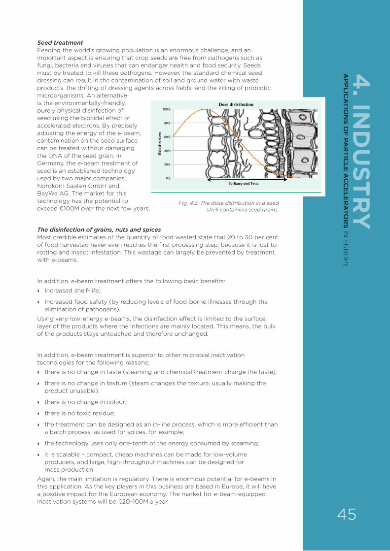
4. IN
DU
STRY
© Fraunhofer FEPpage 1
Dipl.-Ing. André Weidauer
How does it workBasic principle
0%
20%
40%
60%
80%
100%
Rel
ativ
e do
se
Perikarp und Testa
Dose distribution
Seed treatmentFeeding the world’s growing population is an enormous challenge, and an important aspect is ensuring that crop seeds are free from pathogens such as fungi, bacteria and viruses that can endanger health and food security. Seeds must be treated to kill these pathogens. However, the standard chemical seed dressing can result in the contamination of soil and ground water with waste products, the drifting of dressing agents across fields, and the killing of probiotic microorganisms. An alternative is the environmentally-friendly, purely physical disinfection of seed using the biocidal e¥ect of accelerated electrons. By precisely adjusting the energy of the e-beam, contamination on the seed surface can be treated without damaging the DNA of the seed grain. In Germany, the e-beam treatment of seed is an established technology used by two major companies, Nordkorn Saaten GmbH and BayWa AG. The market for this technology has the potential to exceed €100M over the next few years.
The disinfection of grains, nuts and spicesMost credible estimates of the quantity of food wasted state that 20 to 30 per cent of food harvested never even reaches the first processing step, because it is lost to rotting and insect infestation. This wastage can largely be prevented by treatment with e-beams.
In addition, e-beam treatment o¥ers the following basic benefits:
› Increased shelf-life;
› Increased food safety (by reducing levels of food-borne illnesses through the elimination of pathogens).
Using very-low-energy e-beams, the disinfection e¥ect is limited to the surface layer of the products where the infections are mainly located. This means, the bulk of the products stays untouched and therefore unchanged.
In addition, e-beam treatment is superior to other microbial inactivation technologies for the following reasons:
› there is no change in taste (steaming and chemical treatment change the taste);
› there is no change in texture (steam changes the texture, usually making the product unusable);
› there is no change in colour;
› there is no toxic residue;
› the treatment can be designed as an in-line process, which is more e§cient than a batch process, as used for spices, for example;
› the technology uses only one-tenth of the energy consumed by steaming;
› it is scalable – compact, cheap machines can be made for low-volume producers, and large, high-throughput machines can be designed for mass production.
Again, the main limitation is regulatory. There is enormous potential for e-beams in this application. As the key players in this business are based in Europe, it will have a positive impact for the European economy. The market for e-beam-equipped inactivation systems will be €20–100M a year.
Fig. 4.3: The dose distribution in a seed shell containing seed grains.
45
AP
PLIC
AT
ION
S OF
PAR
TIC
LE A
CC
ELE
RA
TOR
S IN E
UR
OP
E

2D printingVery low-energy e-beams have been used for many decades for curing inks printed with the classic printing technologies such as o¥set and flexographic printing. However, these technologies are not well adapted to recent trends, with lot sizes becoming ever smaller. The disruption of this industry via digital inkjet printing is already underway, and the number of inkjet printers delivered annually has already surpassed the number of traditional printing presses.
New, compact e-beam accelerators are on the market, making it possible to integrate an e-beam curing-module right inside an industrial inkjet printer, taking the place of the UV lamps currently used. This would allow these printers to produce food-safe packaging material, which is the biggest demand driver for printed materials.
The use of e-beam technology and e-beam curable inks has had no major impact on the design of the printing machines. However, at the moment, there are no e-beam-curable inks for one of the three main printing technologies, rotogravure – but manufacturers in this market are trying to move to one of the other two types, o¥set or flexographic printing, as these are cheaper. For smaller and midsize runs, o¥set and flexographic printing are more cost-e¥ective, and the production runs nowadays are becoming ever smaller, as there are much greater variations in the design of packaging.
In the packaging printing process, carton board, film, paper and aluminium or other web-based materials are the most common substrates. E-beam-curable inks and coatings are being applied on these substrates and are cured with an e-beam device. These inks are an alternative to solvent-based inks (for rotogravure and flexographic printing) and UV inks (for o¥set and flexographic printing). They are cured instantly and completely, and the product can be further processed immediately.
Advantages of e-beam curing include the following:
› it is a clean process;
› it o¥ers instant curing with no temperature impact;
› there are no volatile organic compound emissions;
› photo-initiators in the inks for activating the curing process are not needed;
› energy consumption is low.
› it is a controlled and precisely adjustable process o¥ering a high stability of dose during the process;
› the curing is complete, leaving no residual unsaturated monomers;
› there is no filtering of the energy through colour pigments (colour-blind curing process), and the penetration depth is precisely adjustable;
› the heating impact on the substrate is low (temperature-sensitive substrates, for example shrink films, can be processed);
› e-beams have the smallest carbon footprint of any technology.
Packaging printing with e-beam-curable inks has – when compared with the other printing technologies – no limitations. The highest print quality can be reached, and additional steps like overprint varnish or laminating can be also done with e-beam technology. E-beam-curable inks and varnishes have better mechanical properties, and deliver the highest physical stability.
3D printingTwo of the dominant technologies in 3D printing use UV lamps to cure the jetted polymer. This method has several limitations:
› A slow linear speed. The power density of these lamps that ride around with the printheads is extremely low. Either they have to run with very low linear speeds or they need highly-reactive resins. Usually, they require both.
› A slow build rate. UV light does not penetrate far in opaque materials. Thus, the thickness of each layer must be very thin or else it will not be hardened. This results in a very slow build speed.
4. I
ND
UST
RY
46
AP
PLI
CA
TIO
NS
OF
PA
RT
ICLE
AC
CE
LER
ATO
RS
IN E
UR
OP
E

4. IN
DU
STRY
› A limited portfolio of materials. Because of the above constraints, the selection of materials available to designers is limited.
› High-cost materials. Highly reactive resins are much more expensive than normal resins.
› Low strength in the z (perpendicular) direction. As UV light does not penetrate far into a given material, it cannot reach through the layer being jetted to the layer underneath, and thus the adhesion between the layers is weak. Parts printed with these technologies are strong in the x,y direction, but weak in the z direction. That is why they are rarely used for anything other than modelling, rapid prototyping, and non-functional toys.
A 3D printer using a very low-energy e-beam to cure the jetted material would remove all five of the above bottlenecks. Such a machine would require a miniature e-beam lamp and power supply. The technology exists to develop such an e-beam ‘engine’, but to date, this has not been done. This is thus another opportunity with potential to build hundreds to thousands of units per year.
Lacquering and coatingIn this application, the e-beam serves both to cure the coating and to bond it to the substrate. Very low-energy e-beams have been used for this purpose for many decades, with large, continuously-pumped systems. The availability of compact e-beam accelerators opens up opportunities for decentralising production, smaller runs and customisation. The market for e-beam accelerators in this application will grow slowly over the next decade.
GraftingE-beam-grafting is a frontier application with enormous potential. Here, e-beams are used to bond together materials that would otherwise not bond, or would bond only with the use of toxic chemicals. Examples include:
› bonding biocompatible molecules to dialysis membranes to eliminate side-e¥ects after dialysis treatment;
› bonding enzymes to membranes to extend the useful life of filters;
› bonding vitamin E to high-density polyethylene to increase dramatically its wear-resistance;
These are just a few of the hundreds of examples in which the e¥ect of e-beams has been proven. Required now is a) the investigation of new, even more highly-functionalised smart materials; and b) pilot lines to prove the industrial viability of very low-energy e-beams for the in-line production of new materials.
4.2.2.2. Thermal e-beam applicationsThere are a number of approaches to exploiting the thermal e¥ects of e-beams. The most important are welding, melting and evaporation, but local surface-modification and drilling are also of significance.
47
AP
PLIC
AT
ION
S OF
PAR
TIC
LE A
CC
ELE
RA
TOR
S IN E
UR
OP
E
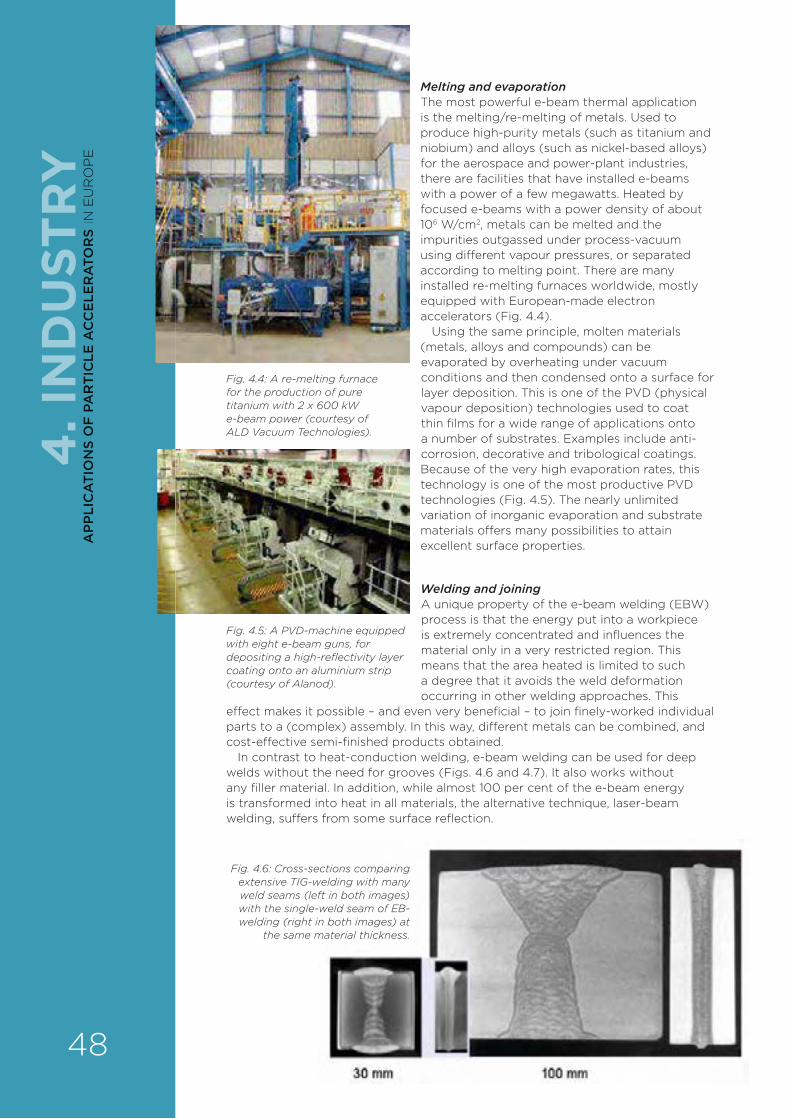
Fig. 4.5: A PVD-machine equipped with eight e-beam guns, for depositing a high-reflectivity layer coating onto an aluminium strip (courtesy of Alanod).
Fig. 4.6: Cross-sections comparing extensive TIG-welding with many weld seams (left in both images) with the single-weld seam of EB-welding (right in both images) at
the same material thickness.
Melting and evaporationThe most powerful e-beam thermal application is the melting/re-melting of metals. Used to produce high-purity metals (such as titanium and niobium) and alloys (such as nickel-based alloys) for the aerospace and power-plant industries, there are facilities that have installed e-beams with a power of a few megawatts. Heated by focused e-beams with a power density of about 106 W/cm2, metals can be melted and the impurities outgassed under process-vacuum using di¥erent vapour pressures, or separated according to melting point. There are many installed re-melting furnaces worldwide, mostly equipped with European-made electron accelerators (Fig. 4.4).
Using the same principle, molten materials (metals, alloys and compounds) can be evaporated by overheating under vacuum conditions and then condensed onto a surface for layer deposition. This is one of the PVD (physical vapour deposition) technologies used to coat thin films for a wide range of applications onto a number of substrates. Examples include anti-corrosion, decorative and tribological coatings. Because of the very high evaporation rates, this technology is one of the most productive PVD technologies (Fig. 4.5). The nearly unlimited variation of inorganic evaporation and substrate materials o¥ers many possibilities to attain excellent surface properties.
Welding and joiningA unique property of the e-beam welding (EBW) process is that the energy put into a workpiece is extremely concentrated and influences the material only in a very restricted region. This means that the area heated is limited to such a degree that it avoids the weld deformation occurring in other welding approaches. This
e¥ect makes it possible – and even very beneficial – to join finely-worked individual parts to a (complex) assembly. In this way, di¥erent metals can be combined, and cost-e¥ective semi-finished products obtained.
In contrast to heat-conduction welding, e-beam welding can be used for deep welds without the need for grooves (Figs. 4.6 and 4.7). It also works without any filler material. In addition, while almost 100 per cent of the e-beam energy is transformed into heat in all materials, the alternative technique, laser-beam welding, su¥ers from some surface reflection.
Fig. 4.4: A re-melting furnace for the production of pure titanium with 2 x 600 kW e-beam power (courtesy of ALD Vacuum Technologies).4
. IN
DU
STR
Y
48
AP
PLI
CA
TIO
NS
OF
PA
RT
ICLE
AC
CE
LER
ATO
RS
IN E
UR
OP
E
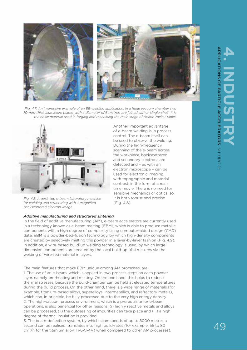
4. IN
DU
STRYAnother important advantage
of e-beam welding is in process control. The e-beam itself can be used to observe the welding. During the high-frequency scanning of the e-beam across the workpiece, backscattered and secondary electrons are detected and – as with an electron microscope – can be used for electronic imaging, with topographic and material contrast, in the form of a real-time movie. There is no need for sensitive mechanics or optics, so it is both robust and precise (Fig. 4.8).
Additive manufacturing and structured sinteringIn the field of additive manufacturing (AM), e-beam accelerators are currently used in a technology known as e-beam melting (EBM), which is able to produce metallic components with a high degree of complexity using computer-aided design (CAD) data. EBM is a powder-bed-fusion technology, by which high-density components are created by selectively melting this powder in a layer-by-layer fashion (Fig. 4.9). In addition, a wire-based build-up welding technology is used, by which large-dimension components are created by the local build-up of structures via the welding of wire-fed material in layers.
The main features that make EBM unique among AM processes, are:1. The use of an e-beam, which is applied in two-process steps on each powder layer, namely pre-heating and melting. On the one hand, this helps to reduce thermal stresses, because the build-chamber can be held at elevated temperatures during the build process. On the other hand, there is a wide range of materials (for example, titanium-based alloys, superalloys, intermetallics, and refractory metals), which can, in principle, be fully processed due to the very high energy density. 2. The high-vacuum process environment, which is a prerequisite for e-beam operations, is also beneficial for other reasons: (i) highly reactive metals and alloys can be processed, (ii) the outgassing of impurities can take place and (iii) a high degree of thermal insulation is provided.3. The beam-deflection system, by which scan-speeds of up to 8000 metres a second can be realised, translates into high build-rates (for example, 55 to 80 cm2/h for the titanium alloy, Ti-6Al-4V) when compared to other AM processes).
Fig. 4.7: An impressive example of an EB-welding application. In a huge vacuum chamber two 70-mm-thick aluminium plates, with a diameter of 6 metres, are joined with a ‘single-shot’. It is
the basic material used in forging and machining the main stage of Ariane-rocket tanks.
Fig. 4.8: A desk-top e-beam laboratory machine for welding and structuring with a magnified backscattered electron-image.
49
AP
PLIC
AT
ION
S OF
PAR
TIC
LE A
CC
ELE
RA
TOR
S IN E
UR
OP
E
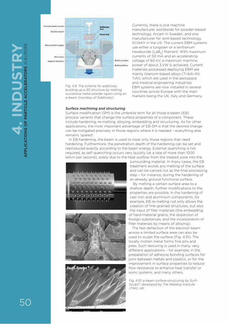
Currently, there is one machine manufacturer worldwide for powder-based technology, Arcam in Sweden, and one manufacturer for wire-based technology, SCIAKY in the US. The current EBM systems use either a tungsten or a lanthanum hexaboride (LaB6) filament. With maximum currents of 50 mA and an accelerating voltage of 60 kV, a maximum machine power of about 3 kW is achieved. Current materials processed deploying EBM are mainly titanium-based alloys (Ti-6Al-4V, TiAl), which are used in the aerospace and medical engineering industries. EBM systems are now installed in several countries across Europe with the main markets being the UK, Italy and Germany.
Surface machining and structuringSurface modification (SM) is the umbrella term for all those e-beam (EB) process variants that change the surface properties of a component. These include hardening, re-melting, alloying, embedding and structuring. As for other applications, the most important advantage of EB-SM is that the desired change can be instigated precisely in those regions where it is needed – everything else remains ‘spared’.
In EB hardening, the beam is used to treat only those regions that need hardening. Furthermore, the penetration depth of the hardening can be set and reproduced exactly according to the beam energy. External quenching is not required, as self-quenching occurs very quickly (at a rate of more than 1000 kelvin per second), solely due to the heat outflow from the treated zone into the
surrounding material. In many cases, the EB treatment avoids any melting of the surface and can be carried out as the final processing step – for instance, during the hardening of an already ground functional surface.
By melting a certain surface area to a shallow depth, further modifications to the properties are possible. In the hardening of cast iron and aluminium components, for example, EB re-melting not only allows the creation of fine-grained structures, but also the input of filler materials (the embedding of hard-material grains, the dispersion of foreign substances, and the incorporation of filler materials by means of alloying).
The fast deflection of the electron beam across a limited surface area can also be used to sculpt the surface (Fig. 4.10). The locally molten metal forms fine pits and piles. Such texturing is used in many, very di¥erent applications – for example, in the preparation of adhesive bonding surfaces for joins between metals and plastics, or for the improvement in surface properties to reduce flow resistance to enhance heat transfer or sonic systems, and many others.
Fig. 4.9: The scheme for additively building up a 3D structure by melting successive metal powder layers using an e-beam (courtesy of Additively).
Fig. 4.10: e-beam surface-structuring by Surfi-Sculpt®, developed by The Welding Institute (TWI), UK.
4. I
ND
UST
RY
50
AP
PLI
CA
TIO
NS
OF
PA
RT
ICLE
AC
CE
LER
ATO
RS
IN E
UR
OP
E
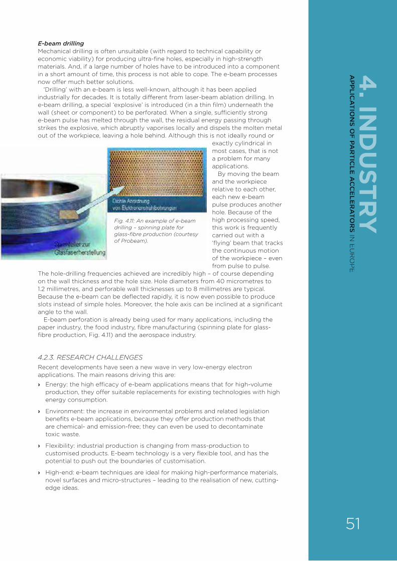
4. IN
DU
STRY
E-beam drillingMechanical drilling is often unsuitable (with regard to technical capability or economic viability) for producing ultra-fine holes, especially in high-strength materials. And, if a large number of holes have to be introduced into a component in a short amount of time, this process is not able to cope. The e-beam processes now o¥er much better solutions.
‘Drilling’ with an e-beam is less well-known, although it has been applied industrially for decades. It is totally di¥erent from laser-beam ablation drilling. In e-beam drilling, a special ‘explosive’ is introduced (in a thin film) underneath the wall (sheet or component) to be perforated. When a single, su§ciently strong e-beam pulse has melted through the wall, the residual energy passing through strikes the explosive, which abruptly vaporises locally and dispels the molten metal out of the workpiece, leaving a hole behind. Although this is not ideally round or
exactly cylindrical in most cases, that is not a problem for many applications.
By moving the beam and the workpiece relative to each other, each new e-beam pulse produces another hole. Because of the high processing speed, this work is frequently carried out with a ‘flying’ beam that tracks the continuous motion of the workpiece – even from pulse to pulse.
The hole-drilling frequencies achieved are incredibly high – of course depending on the wall thickness and the hole size. Hole diameters from 40 micrometres to 1.2 millimetres, and perforable wall thicknesses up to 8 millimetres are typical. Because the e-beam can be deflected rapidly, it is now even possible to produce slots instead of simple holes. Moreover, the hole axis can be inclined at a significant angle to the wall.
E-beam perforation is already being used for many applications, including the paper industry, the food industry, fibre manufacturing (spinning plate for glass-fibre production, Fig. 4.11) and the aerospace industry.
4.2.3. RESEARCH CHALLENGESRecent developments have seen a new wave in very low-energy electron applications. The main reasons driving this are:
› Energy: the high e§cacy of e-beam applications means that for high-volume production, they o¥er suitable replacements for existing technologies with high energy consumption.
› Environment: the increase in environmental problems and related legislation benefits e-beam applications, because they o¥er production methods that are chemical- and emission-free; they can even be used to decontaminate toxic waste.
› Flexibility: industrial production is changing from mass-production to customised products. E-beam technology is a very flexible tool, and has the potential to push out the boundaries of customisation.
› High-end: e-beam techniques are ideal for making high-performance materials, novel surfaces and micro-structures – leading to the realisation of new, cutting-edge ideas.
Fig. 4.11: An example of e-beam drilling – spinning plate for glass-fibre production (courtesy of Probeam).
51
AP
PLIC
AT
ION
S OF
PAR
TIC
LE A
CC
ELE
RA
TOR
S IN E
UR
OP
E

Based on these drivers, the main challenges to fulfil these demands are as follows:For non-thermal e-beam applications
› New high-voltage generator concepts for compact modules.
› New insulation materials/technologies for compact accelerator design.
› New, well-adapted e-beam sources for applications in 3D-shaped products.
› New concepts for electron exit windows in order to lower the usable energy below 80 keV.
› Enlarged sealed (permanently evacuated) e-beam accelerators with a longer lifetime;
› New surfaces with lower X-ray-reflection to reduce shielding e¥orts for inline e-beam systems.
› Miniaturised e-beam systems, suitable for 3D-printers, for example.
› E-beam-curable, ink-jet printable inks.
For thermal electron-beam applications
› Self-diagnostic tools for smart, ‘industry-4.0’ automation, application-realistic simulation of electron emission, electron-beam guiding and electron-substrate interactions for e-beam re-melting, welding and evaporation.
› Electron-beam structuring tools and technologies on scales of 1 to 10 micrometres.
› New powder concepts, better surface quality, larger possible part-size and in-line quality control for additive manufacturing by e-beam melting.
4.2.4. OTHER CHALLENGESLaws and regulationsThe laws and regulations governing ionising radiation are obsolete. They do not di¥erentiate between radiation that penetrates through the entire volume of an object and that which stops at the surface. Both the FDA (US Food and Drug Administration) and USDA (US Department of Agriculture) treat ionising radiation as an additive instead of a production process. Imagine if you had to label a food product because it has been exposed to steam!
The irradiation of food for disinfection is forbidden in most European countries, excluding herbs and spices. It is possible to obtain single-product approvals, but this is an expensive procedure. Furthermore, in most countries, most food products that have been treated with ionising radiation must be labelled as such. The vast majority of brand owners have an irrational fear of irradiation, which means that the public also inherit that fear and so react negatively to the label. They therefore do not pursue the application of ionising radiation as a process to reduce the bio-burden on food products. It seems that the public would prefer the risk of food poisoning.
Updating the regulations and laws governing the application of ionising radiation such that they address low-energy e-beams di¥erently from radiation that penetrates the entire product will:
› reduce food-borne illness;
› expand the world’s food supply;
› exponentially boost the market for accelerators.
As important is the good communication of understanding to consumers and public authorities. Opening the field of the surface-treatment of foods by accelerated electrons will make global food trade safer.
4. I
ND
UST
RY
52
AP
PLI
CA
TIO
NS
OF
PA
RT
ICLE
AC
CE
LER
ATO
RS
IN E
UR
OP
E

4. IN
DU
STRY
4.2.5. PRIORITY AREAS FOR R&DIn addition to those described above, the priority areas derive directly from the challenges:
› Machine development (build-space, e-beam gun and all the hardware connected to it);
› Materials development (powders, new materials, process development).
4.2.6. IMPACT ON INDUSTRY AND EDUCATION4.2.6.1. IndustryEurope is very strong in accelerator technology. A large fraction of the very low-energy e-beam accelerators used in the emerging, high-growth applications will be manufactured in Europe. Furthermore, Europe is the home of the market leaders for machinery manufacturers who integrate these accelerators and serve the emerging, high-growth applications mentioned above.
Altogether, the new applications listed above will add more than €1B to the GNP of European countries, and create thousands of new jobs. For instance, AM technologies are expected to have a major impact on industry, as they expand the manufacturing possibilities dramatically. This is confirmed in, for example, the aerospace sector, where companies like GE, MTU and also Airbus will make the step into serial production within the next few years. E-beam melting (EBM) is expected to have a major share, alongside laser-beam melting and laser metal deposition (LMD) technologies. This expectation arises from the unique characteristics of EBM, which make it the best technology for highly reactive and/or high-melting-point materials (such as titanium and nickel-based alloys, inter-metallics, and refractories), as well as materials that are prone to cracking due to thermal stresses (such as inter-metallics and high-performance steels).
E-beam welding (EBW) has been utilised extremely successfully for decades; all industrialised countries and experienced companies operate very many EBW installations. However, there is still huge potential in this area.
The lack of knowledge amongst designers is a particular obstacle in exploiting the potential o¥ered by e-beam technologies. Their work involves stipulating precisely which design and materials define a future product, and what e¥ective, and especially cost-favourable, fabrication method should be used. What is more, the utilisation properties – that is, the benefits for the subsequent user – are stipulated by their work. A knowledge of the benefits of e-beams must be spread amongst this group of specialists.
4.2.6.2. EducationIn universities and industrial R&D laboratories, there is a considerable knowledge gap regarding the potential use of e-beam technologies in relevant developments with a high industrial impact; the situation is worse in terms of skills-transfer. This bad situation hinders the development and expansion of e§cient production technologies and new products by using e-beams.
The education and training of sta¥ therefore need to be implemented by end-users now. This is expensive and takes a lot of time. It is very important to give universities and R&D facilities the technical and technological possibilities to teach students about irradiation processes. The barrier to using electron emitters in production will decrease significantly if companies already employ educated sta¥.
Installing very low-energy electron accelerators in transportable and/or compact laboratory machines for universities and research facilities creates new markets. To equip such machines with handling tools, adapted to customers’ demands will enlarge the market significantly.
53
AP
PLIC
AT
ION
S OF
PAR
TIC
LE A
CC
ELE
RA
TOR
S IN E
UR
OP
E
4.3. LOW-ENERGY E-BEAMS4.3.1. BACKGROUND AND STATE OF THE ARTLow-energy e-beams in the range between 330 keV and 10 MeV are more penetrating than very low-energy e-beams, which are used to bring about changes on or just under the surfaces of materials. In the case of 10-MeV beams, the penetration of electrons is about 4 cm in water, and the bremsstrahlung radiation emitted from an e/X solid converter has a penetration close to that of gamma-rays. There are nearly 3000 low-energy e-beams accelerators in use.
4.3.2. APPLICATIONS OF LOW-ENERGY E-BEAMS Low-energy e-beams are used for the following applications.
4.3.2.1. Polymer modificationLow-energy electron accelerators have been used for many decades to modify polymers – both natural and synthetic polymers. Well-established industrial technologies for these processes exist, and this is the biggest use of these accelerators. Polymers that have been cross-linked using radiation (see above) show excellent heat and abrasion resistance, and so are used to insulate wires and cables and other applications where good performance at elevated temperatures is essential. Insulating materials include polythene, PVC, fluoropolymers and polyurethane.
Other examples of applications include the production of wire harnesses (assemblies of wires) for electronic devices such as computers and audio-video equipment, and automobile components. Polyurethane covering the outside jacket of sensor cables for anti-lock brake systems is radiation-cross-linked to improve the resistance to hot water. Polybutylene terephthalate (PBT), which is a plastic for the electronics industry, can be cross-linked by radiation, with the result that lead-free soldering materials can be applied.
E-beams are also used to pre-vulcanise components of car tyres in order to prevent any reduction in thickness or displacement of the material during subsequent construction and vulcanisation. Approximately 92 per cent of all radial tyres are processed in this way. The typical electron accelerator used for this is low energy, at around 500 keV, but with a high current of 75 mA to 150 mA. This gives an irradiation dose of 15,000 to 50,000 grays per year. One accelerator can treat between 30,000 and 50,000 tyre plies a day.
In recent years, natural polymers are being re-visited with a renewed interest because of their unique characteristics of inherent biocompatibility, biodegradability and easy availability. The processing of these natural polymers with e-beams is being studied.
4.3.2.2. Materials processingE-beam processing is also used to improve the colour of gemstones, and for modifying semiconducting materials in electronic devices.
Colouring gemstonesE-beam irradiation can alter the electronic properties of gem-quality minerals such that the colour (which depends on the electronic structure in the atoms) can be enhanced. There are several irradiation contract facilities around the world, which convert colourless topaz into blue topaz using an e-beam processing system, sometimes in combination with treatment in a reactor. However, the nature of these irradiation processes is proprietary. In semi-precious stones, transformations include the conversion of beryls into yellow and green beryl, quartz into yellow (citrine), dark brown (smoky) and purple (amethyst) crystals, topaz into imperial or blue topaz, spodumene into yellow or green versions, tourmaline (colourless) into a pink red stone, zircon into a brown to reddish form, and pearls into the valuable brown, blue or black varieties. It should be noted that the deep coloration of certain gems such as blue tourmaline and dark green emerald has been introduced with a judicious combination of heat and radiation.
4. I
ND
UST
RY
54
AP
PLI
CA
TIO
NS
OF
PA
RT
ICLE
AC
CE
LER
ATO
RS
IN E
UR
OP
E
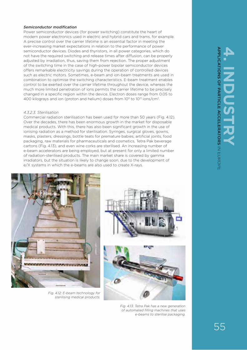
4. IN
DU
STRY
Semiconductor modificationPower semiconductor devices (for power switching) constitute the heart of modern power electronics used in electric and hybrid cars and trams, for example. A precise control over the carrier lifetime is an essential factor in meeting the ever-increasing market expectations in relation to the performance of power semiconductor devices. Diodes and thyristors, in all power categories, which do not have the required switching and release times after di¥usion, can be properly adjusted by irradiation, thus, saving them from rejection. The proper adjustment of the switching time in the case of high-power bipolar semiconductor devices o¥ers remarkable electricity savings during the operation of controlled devices such as electric motors. Sometimes, e-beam and ion-beam treatments are used in combination to optimise the switching characteristics. E-beam treatment enables control to be exerted over the carrier lifetime throughout the device, whereas the much more limited penetration of ions permits the carrier lifetime to be precisely changed in a specific region within the device. Electron doses range from 0.05 to 400 kilograys and ion (proton and helium) doses from 109 to 1013 ions/cm2.
4.3.2.3. SterilisationCommercial radiation sterilisation has been used for more than 50 years (Fig. 4.12). Over the decades, there has been enormous growth in the market for disposable medical products. With this, there has also been significant growth in the use of ionising radiation as a method for sterilisation. Syringes, surgical gloves, gowns, masks, plasters, dressings, bottle teats for premature babies, artificial joints, food packaging, raw materials for pharmaceuticals and cosmetics, Tetra Pak beverage cartons (Fig. 4.13), and even wine corks are sterilised. An increasing number of e-beam accelerators are being employed, but at present for only a limited number of radiation-sterilised products. The main market share is covered by gamma irradiators, but the situation is likely to change soon, due to the development of e/X systems in which the e-beams are also used to create X-rays.
Fig. 4.12: E-beam technology for sterilising medical products.
Fig. 4.13: Tetra Pak has a new generation of automated filling machines that uses
e-beams to sterilise packaging.
55
AP
PLIC
AT
ION
S OF
PAR
TIC
LE A
CC
ELE
RA
TOR
S IN E
UR
OP
E
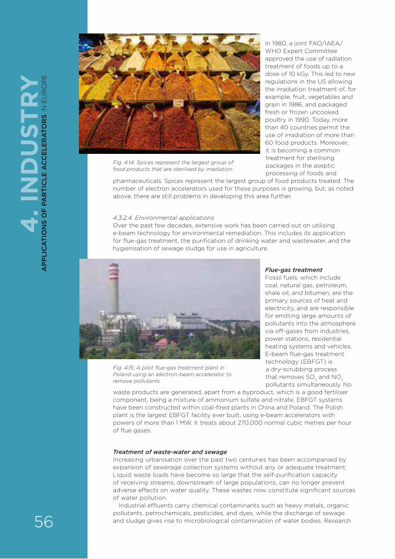
In 1980, a joint FAO/IAEA/WHO Expert Committee approved the use of radiation treatment of foods up to a dose of 10 kGy. This led to new regulations in the US allowing the irradiation treatment of, for example, fruit, vegetables and grain in 1986, and packaged fresh or frozen uncooked poultry in 1990. Today, more than 40 countries permit the use of irradiation of more than 60 food products. Moreover, it is becoming a common treatment for sterilising packages in the aseptic processing of foods and
pharmaceuticals. Spices represent the largest group of food products treated. The number of electron accelerators used for these purposes is growing, but, as noted above, there are still problems in developing this area further.
4.3.2.4. Environmental applicationsOver the past few decades, extensive work has been carried out on utilising e-beam technology for environmental remediation. This includes its application for flue-gas treatment, the purification of drinking water and wastewater, and the hygienisation of sewage sludge for use in agriculture.
Flue-gas treatmentFossil fuels, which include coal, natural gas, petroleum, shale oil, and bitumen, are the primary sources of heat and electricity, and are responsible for emitting large amounts of pollutants into the atmosphere via o¥-gases from industries, power stations, residential heating systems and vehicles. E-beam flue-gas treatment technology (EBFGT) is a dry-scrubbing process that removes SO2 and NOx pollutants simultaneously. No
waste products are generated, apart from a byproduct, which is a good fertiliser component, being a mixture of ammonium sulfate and nitrate. EBFGT systems have been constructed within coal-fired plants in China and Poland. The Polish plant is the largest EBFGT facility ever built, using e-beam accelerators with powers of more than 1 MW. It treats about 270,000 normal cubic metres per hour of flue gases.
Treatment of waste-water and sewageIncreasing urbanisation over the past two centuries has been accompanied by expansion of sewerage collection systems without any or adequate treatment. Liquid waste loads have become so large that the self-purification capacity of receiving streams, downstream of large populations, can no longer prevent adverse e¥ects on water quality. These wastes now constitute significant sources of water pollution.
Industrial e¶uents carry chemical contaminants such as heavy metals, organic pollutants, petrochemicals, pesticides, and dyes, while the discharge of sewage and sludge gives rise to microbiological contamination of water bodies. Research
Fig. 4.14: Spices represent the largest group of food products that are sterilised by irradiation.
Fig. 4.15: A pilot flue-gas treatment plant in Poland using an electron-beam accelerator to remove pollutants.
4. I
ND
UST
RY
56
AP
PLI
CA
TIO
NS
OF
PA
RT
ICLE
AC
CE
LER
ATO
RS
IN E
UR
OP
E

4. IN
DU
STRY
and industrial treatments testify to significant improvements in pollutant biodegradability after the e-beam radiation-oxidation in aerated wastewater. Usually a dose of about 1 to 2 kGy is necessary for the complete transformation of pollutants by biological resistance to a biodegradable state. A high-power accelerator (1 MeV, 400 kW) was applied at a wastewater treatment system in the Republic of Korea (South Korea). This plant treated up to 10,000 cubic metres per day of wastewater from textile-dyeing (from a total of 80,000 cubic metres), and showed good removal of non-degradable organic impurities. Research has shown that sewage sludge from a municipal wastewater treatment plant can be disinfected successfully by exposure to high-energy radiation. About 3 kGy of absorbed dose in sewage sludge removes 99.99 per cent of pathogenic bacteria consistently and reliably in a simple fashion. The irradiated sludge, being pathogen-free, can be beneficially used as manure in agricultural fields, as it is rich in nutrients required for the soil. Because the irradiated sludge is free of bacteria, it can also be used as a medium for growing useful microbes such as Rhizobium and Azotobacter to produce bio-fertilisers, which can be used to enhance crop yields. Furthermore, the e-beams help to break down long-chain organic molecules in the sludge, increasing the e§ciency of bio-gas production for power generation by anaerobic digestion and reducing the time taken and the size of the facility.
4.3.2.5. Special applications regarding biological hazardsConservationThe protection of books, archives and artefacts from destruction caused by insects and microorganisms is one of the main aims in conserving cultural heritage objects. The microbiological burden can also be harmful to the health of librarians and archivists. Currently, the most common method used to sterilise and preserve these materials is ethylene-oxide treatment, which is toxic to humans and harmful to the natural environment. The promising alternative for this technique is ionising radiation, including e-beams for some applications.
Security The anthrax that was sent through the mail in October 2001 caused several deaths and large economic losses in the US. Irradiation has proved to be very e¥ective for decontaminating mail. About 4000 tonnes of letters and 200 tonnes of parcels had been sanitised by the end of 2003, and the units equipped with 10-MeV accelerators are still in operation today.
4.3.3. RESEARCH CHALLENGESApplications in nanotechnologyNanotechnology is one of the fastest growing new areas in science and engineering. E-beams have been exploited in this area for many years, being used to re-arrange atoms and molecules. In the past, radiation chemists working on materials processing followed the same approach as chemists in general, namely, treatment in bulk at energies greater than 300 keV – mostly around 10 MeV. However, new trends in more precise treatment technology have been developed: surface curing, ion-track membranes and controlled-release drug-delivery systems are good examples.
The ability to fabricate structures with nanometre precision is of fundamental importance to any exploitation of nanotechnology. Because electrons with energies of 30 to 100 keV have short wavelengths, the resolution of e-beam nano-lithography is much higher than that of optical lithography. To improve the resolution, electron direct-writing systems applying electrons with an energy as low as 2 keV are proposed to reduce electron-scattering e¥ects.
Other studies concern the formation and synthesis of nanoparticles and nanocomposites. The radiation synthesis of nanoparticles of copper, silver and other metals has been studied. A solution of metal salts is exposed to gamma-rays, and the reactive species that form reduce the metal ions to the metallic state. The formation of aqueous bimetallic clusters by gamma and electron irradiation has also been studied. The development of nanostructures and nanocomposites, including the novel material graphene, is a new field of research. 57
AP
PLIC
AT
ION
S OF
PAR
TIC
LE A
CC
ELE
RA
TOR
S IN E
UR
OP
E

Widening use in decontaminationAnother important field of irradiation research is in environmental applications, in the form of gaseous, liquid and solid e¶uent treatment. The potential of e-beam irradiation in cultural heritage conservation also has to be studied more intensively. Its wider use requires conclusively establishing that irradiation does not lead to unacceptable changes in the functional or decorative properties of the artefact, and its authenticity being compromised.
4.3.4. OTHER CHALLENGESIndustrial development of low-energy, low-cost, compact acceleratorsThe total number of accelerators installed around the world used in radiation processing is close to 3000. Direct, transformer accelerators, single resonant-cavity accelerators and microwave-source-powered linear accelerators have been found to be the most suitable for this. The industrial development of accelerators is still in progress, not only due to new areas of application, but also because of demands for lower cost and more compact machines. The low-energy accelerator capability has not been explored fully up to now.
Dual e-beam–X-ray systemsIn addition, e-beam units equipped with e/X converters are a future of this technology. The concept of e/X conversion has been known for years; a great deal of R&D has been performed in the field and some units have been installed. However, a breakthrough in technology is expected following the implementation of high-power units that are already being tested by IBA in Belgium. Commercial irradiators are now being o¥ered on the market. Double-beam (electron-beam and X-ray) pulsed machines are the future of the market.
More e�cient, reliable machines neededVery important for industrial applications is the reliability of accelerators: the target, at least for environmental applications, must be 8500 hours per year, and these processes need a medium electron-beam energy (1 to 2 MeV), but a high current. Maintenance concepts must include scheduled replacement strategies, and it is necessary that the manufacturing of accelerator components gives very good reliability. The total cost of machine and other technological components must be compatible with conventional technologies, but e-beam technology has to demonstrate better e§ciency.
4.3.5. PRIORITY AREAS FOR R&DThe priority areas for R&D are:New or modernised accelerators New developments require the industrialisation of new solutions, like superconducting RF cavities and magnets, and other accelerator components such as cathodes, klystrons, advanced material windows, and so on. More e§cient means for generating of X-rays on e/X systems should be investigated.
Applications development Further fundamental research into the physical, chemical and biological e¥ects of radiation should be continued. The applications of e-beams in biological systems (sterilisation, biohazards, waste) and materials (nanotechnology, graphene, nanocomposites) should be studied in more detail.
Fig 4.16: IBA’s Easy-e-Beam™ Integrated system for cross-linking small wires for the automotive market.
4. I
ND
UST
RY
58
AP
PLI
CA
TIO
NS
OF
PA
RT
ICLE
AC
CE
LER
ATO
RS
IN E
UR
OP
E

4. IN
DU
STRY
4.3.6. IMPACT ON INDUSTRY AND EDUCATION4.3.6.1. IndustryIonising radiation in the form of energetic electrons and X-rays are being used for many practical applications. Successful irradiation processes provide significant advantages when compared with typical thermal and chemical processes, such as higher throughput rates, reduced energy consumption, less environmental pollution, more precise control over the process, and the manufacture of products with superior qualities. In some applications, radiation processing can produce unique e¥ects that cannot be duplicated by other means. High-energy, high-power beams can modify the physical, chemical and biological properties of materials and commercial products on an industrial scale. Many electron accelerators with a variety of specifications have been built and installed for these purposes. These technologies have been evolving for more than 50 years, and the field is still expanding.
The greatest industrial use of ionising radiation is in the modification of the properties of polymers, including rubber. Ionising radiation finds use in a variety of industrial applications such as wire and cable insulation, tyre manufacturing, the production of polymeric foams, heat-shrinkable films and tubes, the curing of coatings, adhesives and composites, printing, and other technological development. Other applications using ionising radiation include the synthesis of hydrogels, the radiation-curing of polymeric composites, the production of fluoro-additives, and radiation-cured flexography, coatings, adhesives, paints, and printing inks.
The other major use of this radiation technology is the sterilisation of medical devices. Approximately 50 per cent of single-use medical devices (such as syringes and scalpels) in the UK, and 40 to 50 per cent of all disposable medical products manufactured in North America are sterilised by ionising radiation. E-beams, although having a smaller, overall market share than gamma-rays, are the fastest-growing of the radiation processing methodologies, on a percentage basis.
There are other important fields from social point of view: environmental protection and cultural heritage preservation. Municipal and industrial activities lead to environment degradation. E-beam technology may contribute to the environmental protection to a great extent. The e§cient technologies for gas, liquid and solid wastes have been developed. The preservation of world cultural heritage is a key issue for maintaining national identity, and understanding the exchanges among civilisations throughout history. Cultural heritage artefacts that are based on paper, textiles or wood are prone to biological attack under improper conservation conditions. The application of ionising radiation (electrons generated at electron accelerators and X-rays from e/X systems) for the disinfection of artefacts has been successfully demonstrated in recent years, with the participation of museums and libraries.
4.3.6.2. Education and skills transferUniversities should be encouraged to o¥er courses in practical or industrial accelerator technologies and operation to meet the future demands of these applications. EU programmes can also provide important assistance in educating the public on the economic and humanitarian benefits of accelerators.
A good example is the Erasmus 2 project, Joint Innovative Training and Teaching/Learning Programme in Enhancing Development and Transfer of Knowledge on the Application of Ionising Radiation in Materials Processing, which is intended to fill the gap in education quality between di¥erent regions of the EU. Six partner countries – Poland, France, Italy, Lithuania, Romania and Turkey – are involved in this project. Its objectives are:
› to enhance the teaching level in chemistry and materials science in the higher-education sector through intensive lectures delivered by world-recognised scientists active in these research fields;
› to increase students’ industrial competence appropriate to relevant labour markets through visits to, and training in, industrial accelerator facilities;
› to strengthen international cooperation via the Erasmus 2 project;
› to improve the levels of education and research in universities and research institutions;
› to improve their reputation in the world through the cooperation and dissemination of knowledge on the Internet, as well as through workshops and seminars. 59
AP
PLIC
AT
ION
S OF
PAR
TIC
LE A
CC
ELE
RA
TOR
S IN E
UR
OP
E

4.4. ION BEAMSIon beams are used for both analysis and to modify surfaces.
4.4.1. ION BEAM ANALYSIS – STATE OF THE ARTIon beam analysis (IBA) is a suite of analytical techniques that exploits the interactions with matter of rapidly moving (that is, with MeV energies) charged particles (from protons to heavier ions such as gold). The aim is to determine the elemental composition and structure of the surface regions of solids (to depths of about 100 micrometres), inferred from measured quantities such as the characteristic energy spectra of the resulting X-rays, gamma-rays or charged particles emitted (Fig. 4.17).
Since the early 1960s, IBA has provided critical information in many fields – materials science, art and archeology, geology, biomedicine, and environmental studies as a result of the following attributes:
› multi-element sensitivity (right across the Periodic Table from hydrogen to uranium);
› low limits of detection (down to parts per million);
› the ability to provide spatially resolved and quantitative profiling of trace elements;
› highly quantitative (to a few per cent);
› traceable;
› sample preparation unnecessary.
The ability to extract an ion beam, prepared in a vacuum, into an external experimental environment under normal pressure, as well as the fact that measurements are made in a non-destructive and non-invasive manner, has been a major factor in the application of IBA techniques to the study of cultural heritage artefacts in particular (Fig. 4.19). All the strengths mentioned above are of great importance in maintaining the singular usefulness of IBA against a wide range of competitive analytical methods.
IBA covers a family of techniques:
› Elastic or Rutherford backscattering (EBS or RBS), with a particle detector at a backscattering angle, and also nuclear reaction analysis (NRA);
› Particle-induced X-ray emission (PIXE), with an X-ray detector;
› Particle-induced gamma-ray emission (PIGE), with a gamma detector;
› Elastic recoil detection analysis (ERDA) with a particle detector at a forward recoil/scattering angle.
The integration of all these techniques – in a so-called ‘total-IBA’ measurement – allows the complete characterisation of all the elements in a sample.
Fig. 4.17: A pictorial representation of ion beam analysis of a sample.
Fig. 4.18: A 3-MeV proton beam extracted into air.
4. I
ND
UST
RY
60
AP
PLI
CA
TIO
NS
OF
PA
RT
ICLE
AC
CE
LER
ATO
RS
IN E
UR
OP
E
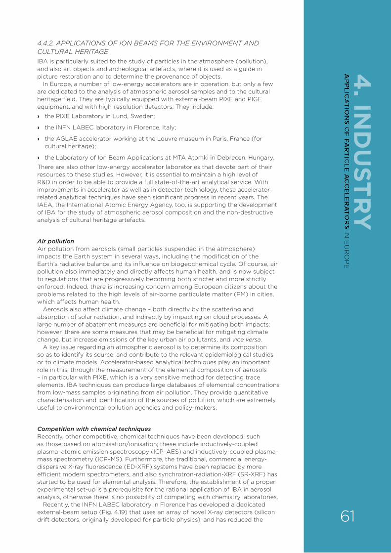
4. IN
DU
STRY
4.4.2. APPLICATIONS OF ION BEAMS FOR THE ENVIRONMENT AND CULTURAL HERITAGEIBA is particularly suited to the study of particles in the atmosphere (pollution), and also art objects and archeological artefacts, where it is used as a guide in picture restoration and to determine the provenance of objects.
In Europe, a number of low-energy accelerators are in operation, but only a few are dedicated to the analysis of atmospheric aerosol samples and to the cultural heritage field. They are typically equipped with external-beam PIXE and PIGE equipment, and with high-resolution detectors. They include:
› the PIXE Laboratory in Lund, Sweden;
› the INFN LABEC laboratory in Florence, Italy;
› the AGLAE accelerator working at the Louvre museum in Paris, France (for cultural heritage);
› the Laboratory of Ion Beam Applications at MTA Atomki in Debrecen, Hungary.
There are also other low-energy accelerator laboratories that devote part of their resources to these studies. However, it is essential to maintain a high level of R&D in order to be able to provide a full state-of-the-art analytical service. With improvements in accelerator as well as in detector technology, these accelerator-related analytical techniques have seen significant progress in recent years. The IAEA, the International Atomic Energy Agency, too, is supporting the development of IBA for the study of atmospheric aerosol composition and the non-destructive analysis of cultural heritage artefacts.
Air pollutionAir pollution from aerosols (small particles suspended in the atmosphere) impacts the Earth system in several ways, including the modification of the Earth’s radiative balance and its influence on biogeochemical cycle. Of course, air pollution also immediately and directly a¥ects human health, and is now subject to regulations that are progressively becoming both stricter and more strictly enforced. Indeed, there is increasing concern among European citizens about the problems related to the high levels of air-borne particulate matter (PM) in cities, which a¥ects human health.
Aerosols also a¥ect climate change – both directly by the scattering and absorption of solar radiation, and indirectly by impacting on cloud processes. A large number of abatement measures are beneficial for mitigating both impacts; however, there are some measures that may be beneficial for mitigating climate change, but increase emissions of the key urban air pollutants, and vice versa.
A key issue regarding an atmospheric aerosol is to determine its composition so as to identify its source, and contribute to the relevant epidemiological studies or to climate models. Accelerator-based analytical techniques play an important role in this, through the measurement of the elemental composition of aerosols – in particular with PIXE, which is a very sensitive method for detecting trace elements. IBA techniques can produce large databases of elemental concentrations from low-mass samples originating from air pollution. They provide quantitative characterisation and identification of the sources of pollution, which are extremely useful to environmental pollution agencies and policy-makers.
Competition with chemical techniquesRecently, other competitive, chemical techniques have been developed, such as those based on atomisation/ionisation; these include inductively-coupled plasma–atomic emission spectroscopy (ICP–AES) and inductively-coupled plasma–mass spectrometry (ICP–MS). Furthermore, the traditional, commercial energy-dispersive X-ray fluorescence (ED-XRF) systems have been replaced by more efficient modern spectrometers, and also synchrotron-radiation-XRF (SR-XRF) has started to be used for elemental analysis. Therefore, the establishment of a proper experimental set-up is a prerequisite for the rational application of IBA in aerosol analysis, otherwise there is no possibility of competing with chemistry laboratories.
Recently, the INFN LABEC laboratory in Florence has developed a dedicated external-beam setup (Fig. 4.19) that uses an array of novel X-ray detectors (silicon drift detectors, originally developed for particle physics), and has reduced the 61
AP
PLIC
AT
ION
S OF
PAR
TIC
LE A
CC
ELE
RA
TOR
S IN E
UR
OP
E
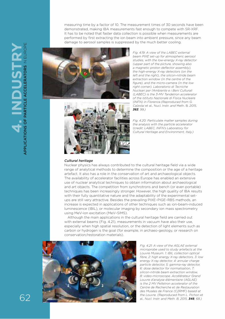
measuring time by a factor of 10. The measurement times of 30 seconds have been demonstrated, making IBA measurements fast enough to compete with SR-XRF. It has to be noted that faster data collection is possible when measurements are performed by first extracting the ion beam into ambient pressure, since any beam damage to aerosol samples is suppressed by the much better cooling.
Fig. 4.19: A view of the LABEC external beam PIXE set-up for atmospheric aerosol studies, with the low-energy X-ray detector (upper part of the picture, showing also a magnetic proton deflector assembly), the high-energy X-ray detectors (on the left and the right), the silicon-nitride beam extraction window (in the centre of the figure), and the micro-camera (in the low right corner). Laboratorio di Tecniche Nucleari per l’Ambiente e i Beni Culturali (LABEC) is the 3-MV Tandetron accelerator of the Istituto Nazionale di Fisica Nucleare (INFN) in Florence.(Reproduced from G. Calzolai et al., Nucl. Instr. and Meth. B, 2015, 363, 99.)
Fig. 4.20: Particulate matter samples during the analysis with the particle accelerator (credit: LABEC, INFN’s Laboratory for Cultural Heritage and Environment, Italy.)
Cultural heritageNuclear physics has always contributed to the cultural heritage field via a wide range of analytical methods to determine the composition or the age of a heritage artefact. It also has a role in the conservation of art and archaeological objects. The availability of accelerator facilities across Europe has enabled an extensive use of nuclear analytical techniques to obtain information about archaeological and art objects. The competition from synchrotrons and bench (or even portable) techniques has been increasingly stronger. However, the high quality of IBA results with their fully quantitative nature and the adaptability of the experimental set-ups are still very attractive. Besides the prevailing PIXE–PIGE–RBS methods, an increase is expected in applications of other techniques such as ion-beam-induced luminescence (IBIL), or molecular imaging by secondary ion mass spectrometry using MeV-ion excitation (MeV–SIMS).
Although the main applications in the cultural heritage field are carried out with external beams (Fig. 4.21), measurements in vacuum have also their use, especially when high spatial resolution, or the detection of light elements such as carbon or hydrogen is the goal (for example, in archaeo-geology, or research on conservation/restoration materials).
Fig. 4.21: A view of the AGLAE external microprobe used to study artefacts at the Louvre Museum. 1: IBIL collection optical fibre, 2: high energy X-ray detectors, 3: low energy X-ray detector, 4: annular charge particle detector, 5: gamma-ray detector, 6: dose detector for normalisation, 7: silicon-nitride beam extraction window, 8: video-microscope. Accélérateur Grand Louvre d’analyse élémentaire (AGLAE) is the 2 MV Pelletron accelerator of the Centre de Recherche et de Restauration des Musées de France (C2RMF) based at the Louvre. (Reproduced from L. Pichon et al., Nucl. Instr. and Meth. B, 2015, 348, 68.)
4. I
ND
UST
RY
62
AP
PLI
CA
TIO
NS
OF
PA
RT
ICLE
AC
CE
LER
ATO
RS
IN E
UR
OP
E
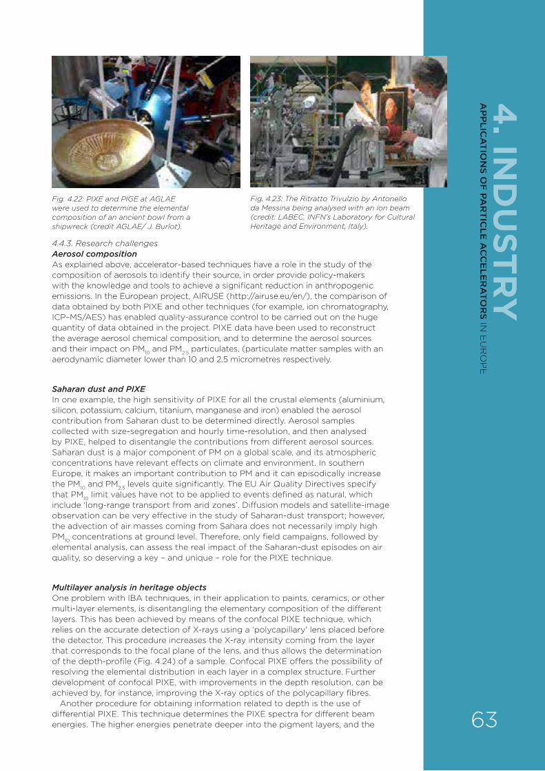
4. IN
DU
STRY
4.4.3. Research challenges Aerosol composition As explained above, accelerator-based techniques have a role in the study of the composition of aerosols to identify their source, in order provide policy-makers with the knowledge and tools to achieve a significant reduction in anthropogenic emissions. In the European project, AIRUSE (http://airuse.eu/en/), the comparison of data obtained by both PIXE and other techniques (for example, ion chromatography, ICP–MS/AES) has enabled quality-assurance control to be carried out on the huge quantity of data obtained in the project. PIXE data have been used to reconstruct the average aerosol chemical composition, and to determine the aerosol sources and their impact on PM10 and PM2.5 particulates, (particulate matter samples with an aerodynamic diameter lower than 10 and 2.5 micrometres respectively.
Saharan dust and PIXEIn one example, the high sensitivity of PIXE for all the crustal elements (aluminium, silicon, potassium, calcium, titanium, manganese and iron) enabled the aerosol contribution from Saharan dust to be determined directly. Aerosol samples collected with size-segregation and hourly time-resolution, and then analysed by PIXE, helped to disentangle the contributions from di¥erent aerosol sources. Saharan dust is a major component of PM on a global scale, and its atmospheric concentrations have relevant e¥ects on climate and environment. In southern Europe, it makes an important contribution to PM and it can episodically increase the PM10 and PM2.5 levels quite significantly. The EU Air Quality Directives specify that PM10 limit values have not to be applied to events defined as natural, which include ‘long-range transport from arid zones’. Di¥usion models and satellite-image observation can be very e¥ective in the study of Saharan-dust transport; however, the advection of air masses coming from Sahara does not necessarily imply high PM10 concentrations at ground level. Therefore, only field campaigns, followed by elemental analysis, can assess the real impact of the Saharan-dust episodes on air quality, so deserving a key – and unique – role for the PIXE technique.
Multilayer analysis in heritage objectsOne problem with IBA techniques, in their application to paints, ceramics, or other multi-layer elements, is disentangling the elementary composition of the di¥erent layers. This has been achieved by means of the confocal PIXE technique, which relies on the accurate detection of X-rays using a ‘polycapillary’ lens placed before the detector. This procedure increases the X-ray intensity coming from the layer that corresponds to the focal plane of the lens, and thus allows the determination of the depth-profile (Fig. 4.24) of a sample. Confocal PIXE o¥ers the possibility of resolving the elemental distribution in each layer in a complex structure. Further development of confocal PIXE, with improvements in the depth resolution, can be achieved by, for instance, improving the X-ray optics of the polycapillary fibres.
Another procedure for obtaining information related to depth is the use of di¥erential PIXE. This technique determines the PIXE spectra for di¥erent beam energies. The higher energies penetrate deeper into the pigment layers, and the
Fig. 4.22: PIXE and PIGE at AGLAE were used to determine the elemental composition of an ancient bowl from a shipwreck (credit AGLAE/ J. Burlot).
Fig. 4.23: The Ritratto Trivulzio by Antonello da Messina being analysed with an ion beam (credit: LABEC, INFN’s Laboratory for Cultural Heritage and Environment, Italy).
63
AP
PLIC
AT
ION
S OF
PAR
TIC
LE A
CC
ELE
RA
TOR
S IN E
UR
OP
E

corresponding PIXE spectra are more sensitive to the elemental composition of the deeper layers. In general, the use of total-IBA methods, at least of PIXE and RBS together, enables the full quantification of layered samples when the sample structure is not known, whereas SR–XRF and ED–XRF do not.
Interior analysis of metal objectsHigher-energy accelerators, delivering proton beams with energies from 20 to 70 MeV, can also be used for cultural heritage studies, to analyse, for instance, the interior of metal artefacts without interference from surface e¥ects. The bulk analysis of cultural heritage samples containing heavy elements exploits the detection of the high-energy X-rays that are produced with reasonably high intensity at these higher beam energies.
4.4.4. PRIORITY AREAS FOR R&DSince their birth, IBA techniques have been applied largely to the study of problems related to environmental science, cultural heritage, biology, and geology, providing compositional and mapping information in a non-destructive way – and thanks also to the use of particle beams extracted from the accelerator beamline into the external atmosphere. With the advent of other, competitive techniques, IBA can still continue to provide an invaluable contribution to study such problems related to societal challenges, although technical developments in accelerators, focusing systems, detectors and data-collection systems, and the software to process the datasets, are needed to consolidate and enhance the potential and the success of ion-beam techniques. In particular:
› The design of small-footprint, or even portable, accelerators could pave the road for the application of IBA to cultural heritage objects directly in their host museums or in archaeological sites .
› The standardisation of the synergic use of several IBA techniques (for example, PIXE/PIGE/EBS) with external or in-vacuum beams, both micro- and millimetre-sized, with imaging/mapping capabilities over an area of a square-centimetre.
› The development of compact and highly e§cient detection systems, and the implementation of appropriate data-analysis codes.
› IBA data simulation/analysis codes should implement the analysis of laterally inhomogeneous sample structures, rough surfaces in a very general way, for example, paint layers, aerosol dust samples, geological samples, and so on. This is very important in improving the quality of RBS data, for instance.
4.4.5. ION IMPLANTATION Ion implantation is a significant industrial process in which accelerated ions or protons impinge onto the surface of a material and become implanted, thus altering the surface chemical and/or physical properties of the material. It is an enabling fabrication technology both for the huge semiconductor industry worldwide, and also for manipulating the chemistry of near-surface layers of modern functional materials.
Implantation also provides a highly sensitive means of analysing the composition of surfaces and thin films, through secondary ion mass spectrometry (SIMS). The ion beam ejects secondary ions from a surface layer about a nanometre or so thick; they are then collected and identified from their mass-to-charge ratios measured in a mass spectrometer. SIMS can detect minute amounts of elements but is not
Fig. 4.24: A graphical representation of a typical confocal micro-PIXE geometry. A rectangular ion micro-beam (yellow) irradiates a sample (green object), which is observed though the sensitive detection-volume of a polycapillary lens (the red surface represents an iso-surface of the lens acceptance for a given X-ray energy). (Reproduced from D. Sokaras et al., J. Anal. At. Spectrom., 2009, 24, 611.)
4. I
ND
UST
RY
64
AP
PLI
CA
TIO
NS
OF
PA
RT
ICLE
AC
CE
LER
ATO
RS
IN E
UR
OP
E
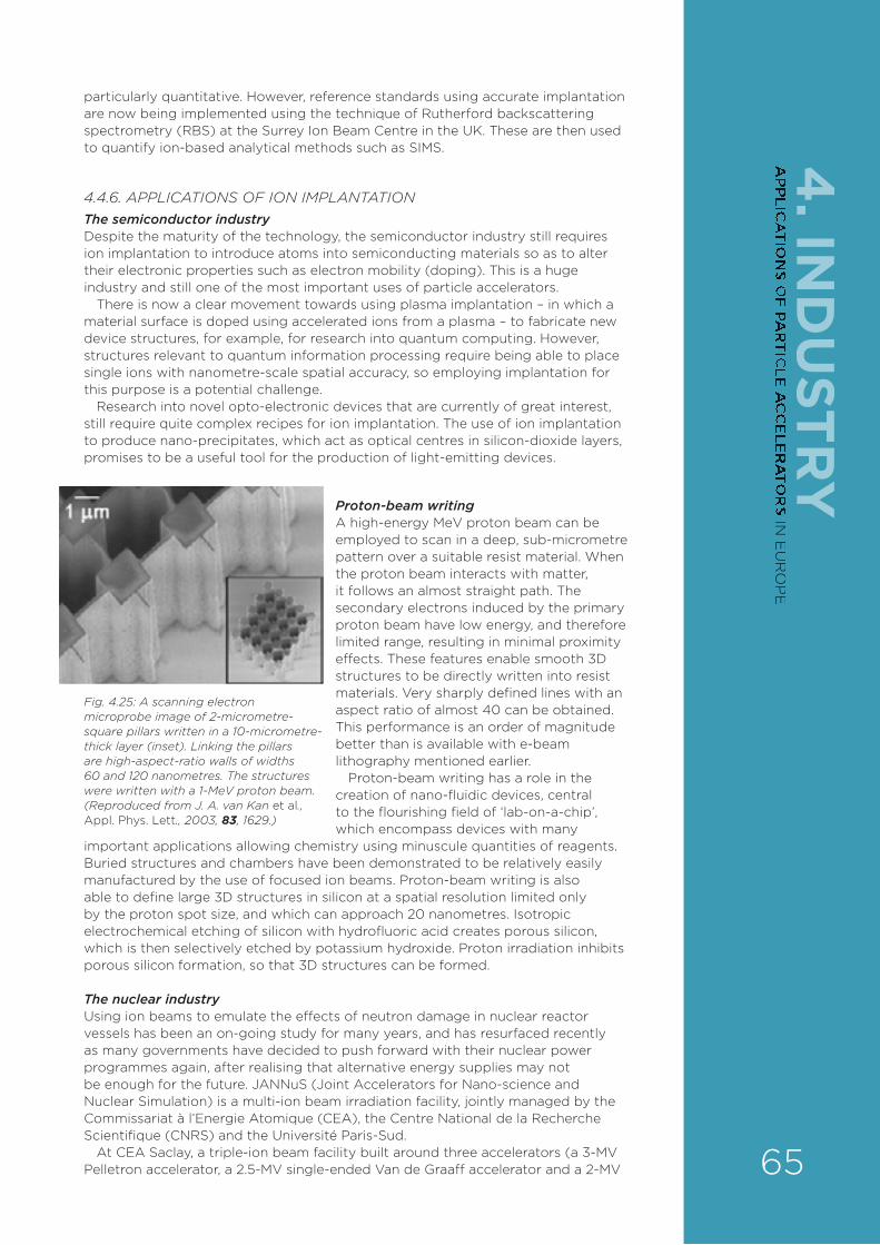
4. IN
DU
STRY
particularly quantitative. However, reference standards using accurate implantation are now being implemented using the technique of Rutherford backscattering spectrometry (RBS) at the Surrey Ion Beam Centre in the UK. These are then used to quantify ion-based analytical methods such as SIMS.
4.4.6. APPLICATIONS OF ION IMPLANTATION The semiconductor industryDespite the maturity of the technology, the semiconductor industry still requires ion implantation to introduce atoms into semiconducting materials so as to alter their electronic properties such as electron mobility (doping). This is a huge industry and still one of the most important uses of particle accelerators.
There is now a clear movement towards using plasma implantation – in which a material surface is doped using accelerated ions from a plasma – to fabricate new device structures, for example, for research into quantum computing. However, structures relevant to quantum information processing require being able to place single ions with nanometre-scale spatial accuracy, so employing implantation for this purpose is a potential challenge.
Research into novel opto-electronic devices that are currently of great interest, still require quite complex recipes for ion implantation. The use of ion implantation to produce nano-precipitates, which act as optical centres in silicon-dioxide layers, promises to be a useful tool for the production of light-emitting devices.
Proton-beam writingA high-energy MeV proton beam can be employed to scan in a deep, sub-micrometre pattern over a suitable resist material. When the proton beam interacts with matter, it follows an almost straight path. The secondary electrons induced by the primary proton beam have low energy, and therefore limited range, resulting in minimal proximity e¥ects. These features enable smooth 3D structures to be directly written into resist materials. Very sharply defined lines with an aspect ratio of almost 40 can be obtained. This performance is an order of magnitude better than is available with e-beam lithography mentioned earlier.
Proton-beam writing has a role in the creation of nano-fluidic devices, central to the flourishing field of ‘lab-on-a-chip’, which encompass devices with many
important applications allowing chemistry using minuscule quantities of reagents. Buried structures and chambers have been demonstrated to be relatively easily manufactured by the use of focused ion beams. Proton-beam writing is also able to define large 3D structures in silicon at a spatial resolution limited only by the proton spot size, and which can approach 20 nanometres. Isotropic electrochemical etching of silicon with hydrofluoric acid creates porous silicon, which is then selectively etched by potassium hydroxide. Proton irradiation inhibits porous silicon formation, so that 3D structures can be formed.
The nuclear industry Using ion beams to emulate the e¥ects of neutron damage in nuclear reactor vessels has been an on-going study for many years, and has resurfaced recently as many governments have decided to push forward with their nuclear power programmes again, after realising that alternative energy supplies may not be enough for the future. JANNuS (Joint Accelerators for Nano-science and Nuclear Simulation) is a multi-ion beam irradiation facility, jointly managed by the Commissariat à l’Energie Atomique (CEA), the Centre National de la Recherche Scientifique (CNRS) and the Université Paris-Sud.
At CEA Saclay, a triple-ion beam facility built around three accelerators (a 3-MV Pelletron accelerator, a 2.5-MV single-ended Van de Graa¥ accelerator and a 2-MV
Fig. 4.25: A scanning electron microprobe image of 2-micrometre-square pillars written in a 10-micrometre-thick layer (inset). Linking the pillars are high-aspect-ratio walls of widths 60 and 120 nanometres. The structures were written with a 1-MeV proton beam. (Reproduced from J. A. van Kan et al., Appl. Phys. Lett., 2003, 83, 1629.)
65
AP
PLIC
AT
ION
S OF
PAR
TIC
LE A
CC
ELE
RA
TOR
S IN E
UR
OP
E
tandem) allows the simultaneous emulation of neutron-induced damage and atom production in nuclear materials using protons, alpha particles and heavy-ion beams. This facility is also devoted to modifying, in a fully controlled way, the properties of materials, and to synthesising new phases by ion implantation or irradiation. In addition, the evolution of both the chemical composition and the microstructure of irradiated materials can be quantified using available online IBA techniques. Such a facility has no other equivalent in Europe, and plays an essential role in the multi-scale modelling of irradiation e¥ects in materials. It fills the gap between existing electron-irradiation equipment and high-energy accelerators.
Fig. 4.26: In this micro-machined Stonehenge-like structure, which is 80 micrometres in diameter, the horizontal ‘stones’ are fabricated by a beam of 500-keV protons (range in silicon about 6 micrometres) and the vertical ‘stones’ by 2-MeV protons (range about 48 micrometres). (Reproduced from F. Watt et al., Materials Today, 2007, 10, 20.)
Nanomaterials Ion implantation is still one of the most controllable and reliable techniques for incorporating a precise amount of one material in another. The role of ion implantation in producing buried nano-structures for a whole range of optical, magnetic and electronic applications will continue long into the future. There is no other technique that can compete with ion implantation in precision and accuracy of placing the right constituent and amount where required in a 3D arrangement. The ability to place single ions at depths of nanometres, and with similar spatial resolution, are key to producing nanostructures on a large scale. The analysis of the 3D location of hydrogen in nanostructured materials is di§cult by most other techniques, particularly if they need to be non-destructive, whereas ‘hydrogen tomography’ can be achieved by IBA. Most alternative techniques relying on interactions with electron shells on atoms have a general problem with light-element detection. Absolute quantification and accuracy of IBA in light-element analysis is an unique and important asset.
PolymersThe mixing of multi-layers and the functionalising of surfaces remain both an interesting research tool for investigating the immiscibility of materials and for creating new material phases. IBA methods have been crucial in understanding the mixing and de-mixing behaviour of polymers, leading to many novel and highly useful types of devices and materials. Plastic electronics is now a huge market, as also is plastic packaging and coating. Polymer chemists have investigated the inter-di¥usion structures of miscible and immiscible polymers, and various sorts of coatings have now been made in the fabrication of, for example, organic light-
Fig. 4.27: The JANNuS triple-beam facility at CEA Saclay in France.
4. I
ND
UST
RY
66
AP
PLI
CA
TIO
NS
OF
PA
RT
ICLE
AC
CE
LER
ATO
RS
IN E
UR
OP
E

4. IN
DU
STRY
emitting diodes (OLEDs), organic photovoltaic (PV) cells, polymer field-e¥ect transistors (FETs), and materials with a high potential for photonic applications. IBA (and in particular NRA, see above) can help answer the basic science questions, giving a new understanding essential for developing all these uses.
Many polymers contain only carbon and hydrogen, and are therefore indistinguishable in their elemental composition from the point of view of NRA. To obtain the depth profile of one polymer in another, therefore, one polymer is ‘deuterated’, that is, hydrogen atoms are replaced by deuterium atoms. The depth profile of the deuterium can then be detected by its strong nuclear reaction with a helium (3He) beam, and di¥usion coe§cients for the molecules involved are obtained directly from a parametrised fit to multiple NRA spectra.
4.4.7. PRIORITY AREAS FOR R&D Improvement in charge integration, particularly of scanned beams to improve dosimetry and the uniformity of implantation is required to keep up with the demands for high precision and uniform implantation of materials. This is the over-riding benefit that is achieved by directed ion implantation, and this advantage over other, less controllable, but cheaper, techniques needs to be maintained.
Ion-source development specifically aimed at improving micro-beams, that is, high brightness, is essential if micro-probes are really to compete with other technologies and to provide fabrication and analysis of structures at the nanoscale.
As outlined in a review conducted as part of the horizon scanning activities of the SPIRIT (Support of Public and Industrial Research using Ion Beam Technology) consortium, it was noted that currently there is not a ‘holistic’ approach to equipment for ion-beam techniques. There are accelerator manufacturers, beam-line suppliers and detector suppliers, and each system is manufactured and designed independently. One of the things preventing ion-beam techniques from competing with other techniques is the cost of ownership of the equipment and the large space requirements to house the equipment. Indeed, little has been done over the years to shrink the size of the accelerators that are used. A more ‘open source’ approach to accelerator design could help make new desktop units suitable for ion-beam applications, lowering overheads and improving reliability.
New types of accelerators also need to be considered – for example, those using high-energy laser beams. Such accelerators have the potential to realise very high-energy ion beams (hundreds of MeV), but their applications at lower energies should also be considered. Also, small footprint, flexible accelerators using positive ions with low beam-energy spread and emittance would help lower the cost of ownership and reduce the cost of both analysis and implantation.
4.4.8. IMPACT ON INDUSTRY AND EDUCATION/SKILLS TRANSFER For ion beams to be exploited successfully in the areas discussed above, it is essential to have enough trained early-stage researchers capable of understanding the use of ion beams for both the analysis and modification of materials. Training should also aim at gaining ‘real-world’ experience and ‘business-facing skills’ with the private and public sectors. Excluding the now-concluded Marie Curie Initial Training Network SPRITE, currently there is no European programme that directly supports students to develop skills in this area. SPRITE was a multi-disciplinary European training network which brought together Europe’s premier research institutes in the technology and applications of ion beams.
Collaboration with United Nations agencies – for instance, the International Atomic Energy Agency (IAEA) – should be pursued. It would o¥er a further dimension to education and skills transfer, as the researchers would have the opportunity to work within a global context and to interact with scientists from all over the world.
The implementation of appropriate training, including the transfer of capabilities across generational, institutional and geographical barriers, is crucial. This could be achieved by establishing networks for trans-institutional knowledge-transfer, the sharing of agreed common training materials and standard operating procedures, defining competency classes (technicians, engineers, young scientists, experienced scientists), raising resources for workshops, and establishing formal exchange processes. 67
AP
PLIC
AT
ION
S OF
PAR
TIC
LE A
CC
ELE
RA
TOR
S IN E
UR
OP
E
4.5. KEY RECOMMENDATIONS FOR APPLICATIONS OF ACCELERATORS TO INDUSTRYVery low-energy e-beamsThe view from industry and research organisations in order of priority is:
› Invest in R&D by o©ering suitable support programmes for technology development.
› Invest in the development of the next generation of e-beam technologies, including peripheral components, such as high-voltage power supplies, to create more compact, more robust systems for industrial use – that is, systems that are easy to handle, ready for Industry 4.0, and cheap and simple for manufacturing low-level products.
› Lobby for the updating of laws with respect to the specialities of very low-energy electron irradiation.
› Lobby for the updating of laws regarding food irradiation.
› Invest in basic education and training in the area of electron-beam technologies and its diverse applications and possibilities.
Low-energy electron beams › There is a need for strong programmes supported by the governments to move
e-beam technology from the laboratory to industry.
› There is a need to strengthen the connections between end-users and suppliers. The ARIES H2020 project can play a pivotal role in achieving this aim.
› There is a growing use of low-energy e-beam accelerators for the curing of inks, coatings and adhesives.
› Many existing applications require accelerators with powers of tens of kW, but with lower costs, higher eªciency, and simpler operation. The evolution of existing industrial accelerators can improve performance, reliability, eªciency, and lower costs to some extent.
› There are many emerging and exciting applications that need a higher beam power and eªciency to make them commercially viable. Some require very high power (MW class) and high energy (5 to 10 MeV) with high wall plug eªciencies.
› The wider geographical deployment of established applications, such as tyre-rubber crosslinking, the surface treatment of seed for agriculture, municipal wastewater treatment and other applications, needs to be encouraged.
› There is a growing need for mobile e-beam facilities for di©erent applications: industrial wastewater treatment, seed disinfestation, environmental remediation, etc.
› Small e-beam facilities including mobile accelerators are needed to develop applications.
› Large government/EU spending on big science accelerators drives the majority of advanced accelerator R&D worldwide. Industrial accelerator builders are often not well connected to these e©orts. The US, Europe and China are now encouraging such connections. Programmes are required.
› Revolutionary accelerator systems based on new technologies, like superconducting RF (SRF) and improved RF systems developed for big-science accelerators, may provide a path to very high-power, high-eªciency accelerators with significantly smaller capital and operating cost, and of substantially reduced size.
The international collaboration between EU institutions and programmes, IAEA and other bodies around the world is a key factor in connecting industrial accelerator groups, research facilities and radiation chemistry laboratories, and enhancing technology transfer, both in accelerator construction and applications.
4. I
ND
UST
RY
68
AP
PLI
CA
TIO
NS
OF
PA
RT
ICLE
AC
CE
LER
ATO
RS
IN E
UR
OP
E

4. IN
DU
STRY
Ion beams › Areas in which the potential of ion beams for the analysis and modification of
materials has not been fully exploited or promises to be further exploited should be identified.
› It is important to identify what is strategically interesting and propose it to industry, and with that show the politicians that ion beams provide industry with commercial value.
› In the application to environmental pollution problems, it is important to remember that nuclear techniques provide only part of the desired information with regard to chemical composition. PIXE practitioners should not limit themselves to PIXE and IBA analyses in general, but try to diversify their activities by also carrying out other chemical and/or physical and optical measurements, and by establishing collaborations with other groups (such as chemists, geologists and physicists).
› In the application to cultural heritage, IBA techniques must focus on non-destructive, high-sensitivity, depth-resolved, quantitative analysis (covering the whole range of elements) of movable cultural heritage objects, to address specific case studies, and maybe provide molecular information as well, whereas portable/transportable and cheaper ED-XRF systems should be routinely used to provide qualitative information for restoration and academic study.
› Although IBA is considered to be non-destructive, since no sampling is needed, the irradiation may cause visible or non-visible, reversible or irreversible changes, depending on the material and the experimental parameters. This might pose a problem in the analysis of cultural heritage objects. An obvious mitigation strategy could be to decrease the beam current and the duration of irradiation. To do that, eªcient detector systems, for example, based on arrays of detectors, are required.
› Outreach material (leaflets, publications) should be produced to provide information to environmental protection agencies, industry, archaeologists and curators on what they can expect from the use of accelerator-based nuclear techniques. For instance, environmental studies are a success story of IBA, having led to a high level of understanding of pollution generation and its dynamics; research has often motivated regulatory decisions, which have benefited the health of tens of millions of people. The modification of materials by ion beams also has a strong societal impact, but it is not easy to communicate; the opportunity for development depends on EU energy policy and energy management organisation.
› Access to ion-beam techniques needs to be facilitated. In the field of cultural heritage science, the access to nuclear physics techniques is not always straightforward. Currently, the IPERION CH (www.iperionch.eu) provides transnational access, free of charge, to large-scale facilities in France (AGLAE, SOLEIL) and Hungary (BNC, MTA Atomki) for users in the field. Nevertheless, these techniques are still not as well-known as they should be. A unique opportunity emerges, with the acceptance of the E-RIHS (European Research Infrastructure on Heritage Science) initiative for the ESFRI Roadmap. E-RIHS will provide state-of-the-art tools and services to the multidisciplinary communities of researchers working to advance knowledge about heritage and strategies for preservation.
69
AP
PLIC
AT
ION
S OF
PAR
TIC
LE A
CC
ELE
RA
TOR
S IN E
UR
OP
E
5. E
NE
RG
Y5. ENERGY
ADVANCED NUCLEAR POWER SOLUTIONS OFFER THE PROMISE OF GENERATING CLEANER, SUSTAINABLE ENERGY FOR THE FUTURE. THE USE OF SUITABLE HIGH-POWER ACCELERATORS IS ESSENTIAL NOT ONLY IN ACHIEVING THAT AIM BUT ALSO IN DEALING WITH LEGACY NUCLEAR WASTE.
Jean-Luc Biarrotte, Alban Mosnier, Ernest Mund and Gert Van den Eynde
5.1. INTRODUCTIONNuclear energy continues to o¥er an excellent prospect for supporting sustainable development because of its minimum contribution to the greenhouse e¥ect. Many decision-makers increasingly accept that nuclear power generation is needed in order to help meet the anticipated future increase in global energy demand.
Concepts for generating nuclear energy depend on two types of nuclear reactions, which release neutrons and gamma-rays:
› the nuclear fission of heavy isotopes such as those of uranium and plutonium;
› the nuclear fusion of hydrogen isotopes, deuterium and tritium.
Both types of nuclear energy have distinct and challenging problems associated with them. In the case of nuclear fission, they are:
› risks of accidents with potential catastrophic consequences;
› and the production of high-level, long-lived radioactive waste, which is considered to be an intolerable legacy to our descendants and will pose a serious engineering challenge for disposal in a safe way.
In the case of nuclear fusion, the technical challenges are considerable and it will still be many years before a commercial nuclear fusion reactor is fully operational.
Meeting some of these challenges requires R&D that inevitably relies on accelerator technology.
5.2. SOLVING NUCLEAR FISSION PROBLEMS5.2.1. CURRENT STATUSIn the past, today and in the near future, nuclear electricity is produced mainly by light water reactors (LWRs), whether pressurised water reactors (PWRs) or boiling water reactors (BWRs). This technology is based on a fission chain reaction induced by thermal (slow) neutrons. However, the fission process in these reactors is in competition with nuclear processes in which neutrons are absorbed: the actinides (the class of heaviest elements in the Periodic Table) present in the fuel (uranium and plutonium in so-called mixed-oxide, or MOX fuel) can also absorb a neutron without provoking fission. By this process, the heavier radioactive isotopes of neptunium, americium and curium are created. These so-called minor actinides (MAs) are typically long-lived and very radio-toxic. On average, for every tonne of fresh (low enriched) uranium loaded in a reactor, the absorption process produces about 12 kg of plutonium and about 2.5 kg of MAs in the spent fuel.
We estimate that the time needed for un-reprocessed spent fuel from an LWR to reach the radio-toxicity level of natural uranium is 170,000 years (Fig. 5.1). Such a time-frame is considered unacceptable for ethical reasons. Plutonium reprocessing (and recycling in MOX fuel) would reduce the ‘cooling time’ to 16,000 years, which is still very long.
5. ACCELERATORS AND ENERGY
Jean-Luc Biarrotte, IPN Orsay, CNRS/IN2P3, Paris-Sud
University, France.
Alban Mosnier, CEA, Gif-sur-Yvette,
France.
Ernest Mund, Université libre de Bruxelles, Belgium.
Gert Van den Eynde, SCK • CEN, Mol,
Belgium.
70
AP
PLI
CA
TIO
NS
OF
PA
RT
ICLE
AC
CE
LER
ATO
RS
IN E
UR
OP
E
5. EN
ER
GY
5.2.2. DESTROYING LONG-LIVED RADIOACTIVE WASTE There is, however, an important solution, which is now being investigated: further separation and nuclear transmutation (to lighter, short-lived isotopes) of these long-lived MAs could bring the cooling time down to 300 years – a much more manageable time-frame – with, say, a final disposal of the residual high-level waste in a suitable geological layer, for example, in clay, salt (in a mine) or in granite.
This raises the question regarding the technology needed to transmute MAs. As mentioned above, with slow neutrons, the competition between fission and capture swings too much towards capture, so generating even more, heavier MAs. However, if the MAs are bombarded with fast neutrons (with an energy above, say, 1 MeV), fission becomes the dominant process. In this way, the MAs will be transmuted into fission products that are radioactive isotopes in the medium mass-range, and typically with much shorter half-lives than those of the parent MAs.
For the e§cient transmutation of MAs, a fast-neutron system is thus crucial. A first option would be a fast-neutron critical reactor like the sodium fast reactor, a technology developed during 1970s and 1980s. This is again of interest in the framework of the most advanced reactor designs – the Generation IV nuclear power plants to be deployed in the 2050s. However, to guarantee the safe operation of such reactors, the MA content must not be greater than 5 per cent.
5.2.3. ACCELERATOR-DRIVEN TRANSMUTATIONA second option for a fast-neutron system would be an accelerator-driven system (ADS), using a heavy liquid metal as a coolant. An ADS consists of a subcritical reactor core, a spallation target and a particle accelerator (see box). The major advantage of this system over a critical reactor is that much larger quantities (up to 40 per cent of the core content) of MAs can be loaded safely for transmutation.
The idea is to use a limited (thanks to the high, allowable concentration of MAs) number of dedicated transmutation systems in the form of ADSs on a regional (European, for example) scale. This then allows for the unhindered deployment of fast reactors for electricity generation using classical reactor fuel, while cleaning up the legacy of nuclear waste from LWRs in ADSs. The ADSs are thus not constructed for electricity production (although power is an available byproduct) but for the reduction of the long-lived, high-level waste legacy.
Fig. 5.1: The time evolution of the radiotoxicity of un-reprocessed and reprocessed spent fuel.
71
AP
PLIC
AT
ION
S OF
PAR
TIC
LE A
CC
ELE
RA
TOR
S IN E
UR
OP
E

AN ACCELERATOR-DRIVEN SYSTEM FOR NUCLEAR TRANSMUTATIONAn ADS consists of three basic building blocks: a particle accelerator (for industrial applications, the particles would be protons), a spallation target and a subcritical reactor core (containing the MAs to be transmuted). The accelerator accelerates the protons up to between 600 and 1000 MeV, and they then collide with the heavy atoms of the spallation target (typically lead, bismuth, tungsten or tantalum) to release neutrons through so-called spallation reactions. Depending on the energy of the protons, the number of neutrons generated can range from a few neutrons per proton to 20 neutrons per proton. These neutrons act as source neutrons to the subcritical core, causing enough fissions (and thus more neutrons) in the core to establish a stable flow of fast-moving neutrons to maintain nuclear transmutation.
5. E
NE
RG
Y
5.2.3.1. The MYRRHA projectAt the European level, a conceptual design for an industrial transmutation facility named EFIT (European Facility for Industrial Transmutation) has been developed within the Sixth Framework Programme, IP-EUROTRANS. This facility is characterised by a subcritical reactor core operating at 400 thermal megawatts (MWth), driven by an 800-MeV proton accelerator. It was shown that a limited number (only seven for Europe) would su§ce to transmute all legacy LWR waste within a time-span of a century, for those EU countries that are now in nuclear phase-out.
Clearly, in order to have an e§cient system, the proton accelerator must be very reliable. Every interruption of the beam (a so-called beam trip) leads to a sharp decrease in neutron population, and therefore in power.
Before continuing the design work on the EFIT system, it is clear that much R&D needs to be done at various engineering levels: subcritical reactor physics, lead and lead–bismuth technology, materials science and so on. A particular challenge is to attain su§cient accelerator reliability. To support these developments, prototypes at di¥erent scales are necessary. As a result, the Belgian Nuclear Research Centre in Mol (SCK-CEN) has been developing a prototype, MYRRHA (Multi-purpose hYbrid Research Reactor for High-tech Applications), for almost 20 years. MYRRHA is based on the ADS concept using an accelerated proton beam of 600-MeV energy with a maximum beam current of 4 mA, which is coupled with a spallation target and a subcritical reactor. MYRRHA will demonstrate the full ADS concept by coupling the three components at a reasonable power level (50 to 100 MWth) to provide feedback about the complete operation.
Fig. 5.2: The layout of the MYRRHA reactor vessel.
As a flexible irradiation facility, MYRRHA will be capable of working in both subcritical and critical modes, so will be able to carry out a range of research programmes:
› the study of the partitioning and transmutation of high-level waste;
› the development of fuels for innovative reactor systems;
› the development of materials for Generation-IV and fusion reactors;
› radioisotope production for medical and industrial applications.
MYRRHA will be cooled by a lead–bismuth eutectic (LBE), and will play an important role in the development of the lead-alloy technology needed for the LFR (Lead Fast Reactor) Generation-IV concept. As the lead technology is related to the development of certain types of SMRs (Small and Modular Reactors), MYRRHA can also play a role as a prototype and demonstrator for such facilities.
72
AP
PLI
CA
TIO
NS
OF
PA
RT
ICLE
AC
CE
LER
ATO
RS
IN E
UR
OP
E
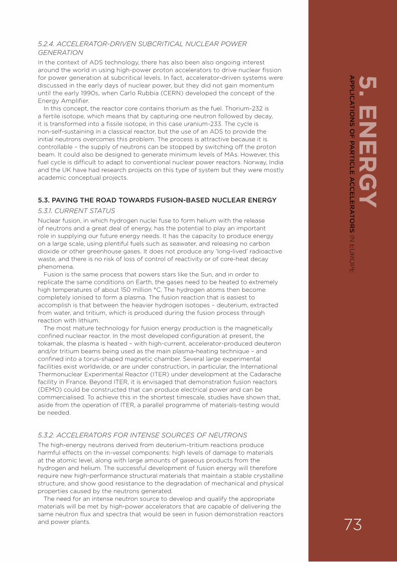
5. EN
ER
GY
5.2.4. ACCELERATOR-DRIVEN SUBCRITICAL NUCLEAR POWER GENERATION In the context of ADS technology, there has also been also ongoing interest around the world in using high-power proton accelerators to drive nuclear fission for power generation at subcritical levels. In fact, accelerator-driven systems were discussed in the early days of nuclear power, but they did not gain momentum until the early 1990s, when Carlo Rubbia (CERN) developed the concept of the Energy Amplifier.
In this concept, the reactor core contains thorium as the fuel. Thorium-232 is a fertile isotope, which means that by capturing one neutron followed by decay, it is transformed into a fissile isotope, in this case uranium-233. The cycle is non-self-sustaining in a classical reactor, but the use of an ADS to provide the initial neutrons overcomes this problem. The process is attractive because it is controllable – the supply of neutrons can be stopped by switching o¥ the proton beam. It could also be designed to generate minimum levels of MAs. However, this fuel cycle is di§cult to adapt to conventional nuclear power reactors. Norway, India and the UK have had research projects on this type of system but they were mostly academic conceptual projects.
5.3. PAVING THE ROAD TOWARDS FUSION-BASED NUCLEAR ENERGY 5.3.1. CURRENT STATUSNuclear fusion, in which hydrogen nuclei fuse to form helium with the release of neutrons and a great deal of energy, has the potential to play an important role in supplying our future energy needs. It has the capacity to produce energy on a large scale, using plentiful fuels such as seawater, and releasing no carbon dioxide or other greenhouse gases. It does not produce any ‘long-lived’ radioactive waste, and there is no risk of loss of control of reactivity or of core-heat decay phenomena.
Fusion is the same process that powers stars like the Sun, and in order to replicate the same conditions on Earth, the gases need to be heated to extremely high temperatures of about 150 million °C. The hydrogen atoms then become completely ionised to form a plasma. The fusion reaction that is easiest to accomplish is that between the heavier hydrogen isotopes – deuterium, extracted from water, and tritium, which is produced during the fusion process through reaction with lithium.
The most mature technology for fusion energy production is the magnetically confined nuclear reactor. In the most developed configuration at present, the tokamak, the plasma is heated – with high-current, accelerator-produced deuteron and/or tritium beams being used as the main plasma-heating technique – and confined into a torus-shaped magnetic chamber. Several large experimental facilities exist worldwide, or are under construction, in particular, the International Thermonuclear Experimental Reactor (ITER) under development at the Cadarache facility in France. Beyond ITER, it is envisaged that demonstration fusion reactors (DEMO) could be constructed that can produce electrical power and can be commercialised. To achieve this in the shortest timescale, studies have shown that, aside from the operation of ITER, a parallel programme of materials-testing would be needed.
5.3.2. ACCELERATORS FOR INTENSE SOURCES OF NEUTRONS The high-energy neutrons derived from deuterium–tritium reactions produce harmful e¥ects on the in-vessel components: high levels of damage to materials at the atomic level, along with large amounts of gaseous products from the hydrogen and helium. The successful development of fusion energy will therefore require new high-performance structural materials that maintain a stable crystalline structure, and show good resistance to the degradation of mechanical and physical properties caused by the neutrons generated.
The need for an intense neutron source to develop and qualify the appropriate materials will be met by high-power accelerators that are capable of delivering the same neutron flux and spectra that would be seen in fusion demonstration reactors and power plants. 73
AP
PLIC
AT
ION
S OF
PAR
TIC
LE A
CC
ELE
RA
TOR
S IN E
UR
OP
E
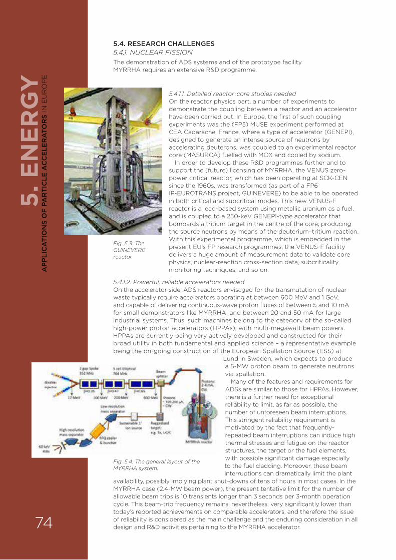
5. E
NE
RG
Y5.4. RESEARCH CHALLENGES 5.4.1. NUCLEAR FISSION The demonstration of ADS systems and of the prototype facility MYRRHA requires an extensive R&D programme.
Fig. 5.3: The GUINEVERE reactor.
5.4.1.2. Powerful, reliable accelerators needed On the accelerator side, ADS reactors envisaged for the transmutation of nuclear waste typically require accelerators operating at between 600 MeV and 1 GeV, and capable of delivering continuous-wave proton fluxes of between 5 and 10 mA for small demonstrators like MYRRHA, and between 20 and 50 mA for large industrial systems. Thus, such machines belong to the category of the so-called high-power proton accelerators (HPPAs), with multi-megawatt beam powers. HPPAs are currently being very actively developed and constructed for their broad utility in both fundamental and applied science – a representative example being the on-going construction of the European Spallation Source (ESS) at
Lund in Sweden, which expects to produce a 5-MW proton beam to generate neutrons via spallation.
Many of the features and requirements for ADSs are similar to those for HPPAs. However, there is a further need for exceptional reliability to limit, as far as possible, the number of unforeseen beam interruptions. This stringent reliability requirement is motivated by the fact that frequently-repeated beam interruptions can induce high thermal stresses and fatigue on the reactor structures, the target or the fuel elements, with possible significant damage especially to the fuel cladding. Moreover, these beam interruptions can dramatically limit the plant
availability, possibly implying plant shut-downs of tens of hours in most cases. In the MYRRHA case (2.4-MW beam power), the present tentative limit for the number of allowable beam trips is 10 transients longer than 3 seconds per 3-month operation cycle. This beam-trip frequency remains, nevertheless, very significantly lower than today’s reported achievements on comparable accelerators, and therefore the issue of reliability is considered as the main challenge and the enduring consideration in all design and R&D activities pertaining to the MYRRHA accelerator.
Fig. 5.4: The general layout of the MYRRHA system.
5.4.1.1. Detailed reactor-core studies neededOn the reactor physics part, a number of experiments to demonstrate the coupling between a reactor and an accelerator have been carried out. In Europe, the first of such coupling experiments was the (FP5) MUSE experiment performed at CEA Cadarache, France, where a type of accelerator (GENEPI), designed to generate an intense source of neutrons by accelerating deuterons, was coupled to an experimental reactor core (MASURCA) fuelled with MOX and cooled by sodium.
In order to develop these R&D programmes further and to support the (future) licensing of MYRRHA, the VENUS zero-power critical reactor, which has been operating at SCK-CEN since the 1960s, was transformed (as part of a FP6 IP-EUROTRANS project, GUINEVERE) to be able to be operated in both critical and subcritical modes. This new VENUS-F reactor is a lead-based system using metallic uranium as a fuel, and is coupled to a 250-keV GENEPI-type accelerator that bombards a tritium target in the centre of the core, producing the source neutrons by means of the deuterium–tritium reaction. With this experimental programme, which is embedded in the present EU’s FP research programmes, the VENUS-F facility delivers a huge amount of measurement data to validate core physics, nuclear-reaction cross-section data, subcriticality monitoring techniques, and so on.
74
AP
PLI
CA
TIO
NS
OF
PA
RT
ICLE
AC
CE
LER
ATO
RS
IN E
UR
OP
E
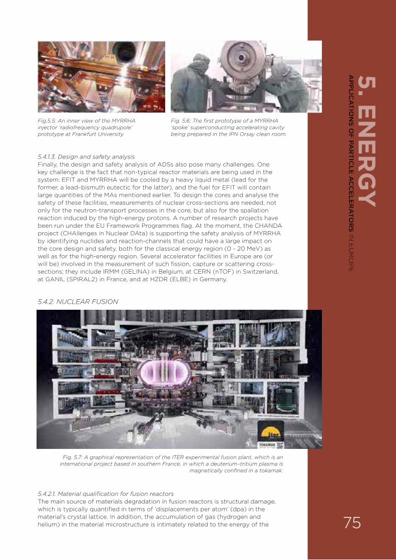
5. EN
ER
GY
5.4.1.3. Design and safety analysisFinally, the design and safety analysis of ADSs also pose many challenges. One key challenge is the fact that non-typical reactor materials are being used in the system: EFIT and MYRRHA will be cooled by a heavy liquid metal (lead for the former, a lead–bismuth eutectic for the latter), and the fuel for EFIT will contain large quantities of the MAs mentioned earlier. To design the cores and analyse the safety of these facilities, measurements of nuclear cross-sections are needed, not only for the neutron-transport processes in the core, but also for the spallation reaction induced by the high-energy protons. A number of research projects have been run under the EU Framework Programmes flag. At the moment, the CHANDA project (CHAllenges in Nuclear DAta) is supporting the safety analysis of MYRRHA by identifying nuclides and reaction-channels that could have a large impact on the core design and safety, both for the classical energy region (0 - 20 MeV) as well as for the high-energy region. Several accelerator facilities in Europe are (or will be) involved in the measurement of such fission, capture or scattering cross-sections; they include IRMM (GELINA) in Belgium, at CERN (nTOF) in Switzerland, at GANIL (SPIRAL2) in France, and at HZDR (ELBE) in Germany.
5.4.2. NUCLEAR FUSION
5.4.2.1. Material qualification for fusion reactorsThe main source of materials degradation in fusion reactors is structural damage, which is typically quantified in terms of ‘displacements per atom’ (dpa) in the material’s crystal lattice. In addition, the accumulation of gas (hydrogen and helium) in the material microstructure is intimately related to the energy of the
Fig.5.5: An inner view of the MYRRHA injector ‘radiofrequency quadrupole’ prototype at Frankfurt University.
Fig. 5.6: The first prototype of a MYRRHA ‘spoke’ superconducting accelerating cavity being prepared in the IPN Orsay clean room.
Fig. 5.7: A graphical representation of the ITER experimental fusion plant, which is an international project based in southern France, in which a deuterium–tritium plasma is
magnetically confined in a tokamak.
75
AP
PLIC
AT
ION
S OF
PAR
TIC
LE A
CC
ELE
RA
TOR
S IN E
UR
OP
E
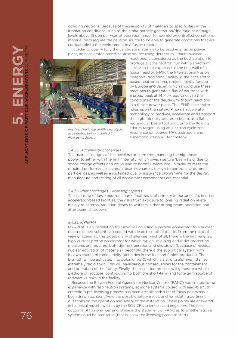
5. E
NE
RG
Ycolliding neutrons. Because of the sensitivity of materials to specificities in the irradiation conditions, such as the alpha-particle generation/dpa ratio at damage levels above 15 dpa per year of operation under temperature-controlled conditions, material tests require the neutron source to be able to generate conditions that are comparable to the environment in a fusion reactor.
In order to qualify fully the candidate materials to be used in a fusion power plant, an accelerator-based neutron source using deuterium–lithium nuclear
reactions, is considered as the best solution to produce a large neutron flux with a spectrum similar to that expected at the first wall of a fusion reactor. IFMIF, the International Fusion Materials Irradiation Facility, is the accelerator-based neutron source project, jointly funded by Europe and Japan, which should use these reactions to generate a flux of neutrons with a broad peak at 14 MeV, equivalent to the conditions of the deuterium–tritium reactions in a fusion power plant. The IFMIF accelerator relies upon the state-of-the-art accelerator technology to produce, accelerate and transport the high-intensity deuteron beam, as a flat rectangular beam footprint, onto the flowing lithium target, using an electron cyclotron-resonance ion source, RF quadrupole and superconducting RF technology.
5.4.2.2. Accelerator challengesThe main challenges of the accelerator stem from handling the high beam power, together with the high intensity, which gives rise to a ‘beam halo’ due to space-charge e¥ects and could lead to harmful beam loss. In order to meet the required performance, a careful beam-dynamics design to control any potential particle loss, as well as a sustained quality assurance programme for the design, manufacture and testing of all accelerator components are essential.
5.4.3. Other challenges – licensing aspectsThe licensing of large neutron source facilities is of primary importance. As in other accelerator-based facilities, the risks from exposure to ionising radiation relate mainly to external radiation doses to workers, either during beam operation and after beam shutdown.
5.4.3.1. MYRRHAMYRRHA is an installation that involves coupling a particle accelerator to a nuclear reactor (albeit subcritical) cooled with lead–bismuth eutectic. From the point of view of licensing, this poses many challenges. First of all, there is the high-energy, high-current proton accelerator for which typical shielding and radio-protection measures are required, both during operation and shutdown (because of residual nuclear activation of materials). Secondly, there is the subcritical system with its own source of radioactivity (actinides in the fuel and fission products). The bismuth will be activated into polonium-210, which is a strong alpha-emitter, so extremely radio-toxic. This will have serious consequences for the containment and operation of the facility. Finally, the spallation process will generate a whole plethora of isotopes, contributing to both the short-term and long-term source of radioactive risks in the facility.
Because the Belgian Federal Agency for Nuclear Control (FANC) had limited-to-no experience with fast-neutron systems, let alone systems cooled with lead–bismuth eutectic, a pre-licensing process has been established: a list of focus points has been drawn up, identifying the possible safety issues, and formulating pertinent questions on the operation and safety of the installation. These points are answered in technical reports written by the SCK-CEN scientists and engineers. The final outcome of this pre-licensing phase is the statement of FANC as to whether such a system could be licensable (that is, allow the licensing phase to start).
Fig. 5.8: The linear IFMIF prototype accelerator, being installed in Rokkasho, Japan.
76
AP
PLI
CA
TIO
NS
OF
PA
RT
ICLE
AC
CE
LER
ATO
RS
IN E
UR
OP
E
5. EN
ER
GY
5.4.3.2. IFMIFConcerning IFMIF, the main source of radiation stems from the lithium target, and the resulting irradiation and contamination needs to be properly assessed. Whereas the release of radioactivity from the accelerator under normal operating conditions might be considered of lower relevance, every e¥ort must be made to minimise the detrimental beam halo, optimise the design of biological shielding and radioactivity confinement, and select low-activation materials in order to optimise maintenance and waiting periods after shutdown.
5.5. PRIORITY AREAS FOR R&DAccelerator R&D for ADS: focus on reliability Besides high-power aspects, the feasibility of ADS systems relies mainly on the use of an e§cient and highly reliable accelerator in order to avoid excessive thermal stresses on the target and especially on the structures of the reactor core. The challenge here is to develop an accelerator concept suited to this goal, so as to demonstrate, through the construction and testing of prototype components, that the level of reliability required by this application – that is, orders of magnitude higher than present state of the art – can be achieved.
The conceptual design of an ADS accelerator has been under development for about 10 years in Europe. These activities have been coordinated by the Accelerator Research Department of IPN Orsay in France through successive EURATOM Framework Programme projects. They advocate the use of a solution based on a superconducting linear accelerator, so as to obtain an e§cient and highly modular machine with great potential in terms of reliability. Since 2011 and the launch of the MAX project supported by EURATOM FP7, these studies have focused mainly on the accelerator for MYRRHA in order to try to provide a consolidated design with a su§cient level of detail to start a possible construction phase in the coming years.
To try to fulfil the very specific reliability requirement (a mean time between failures greater than 250 hours), the MYRRHA linac design is therefore based on several redundancy schemes. In particular, the 17-MeV injector, based on cross-bar accelerating cavities, is doubled to provide a hot standby spare, able to resume beam operation quickly in case of any failure in the main one. Moreover, the main MYRRHA linac, which has spoke and elliptical superconducting RF cavities from 17 to 600 MeV, is designed with significant RF power and gradient overhead throughout the three superconducting sections to ensure enhanced ‘fault-tolerance’ capabilities: RF unit failures are recovered by using a local compensation method (while stopping the beam for not more than 3 seconds), during which the RF fault is compensated for by acting on the RF gradient and phase of the four nearest neighbouring cavities. A dedicated R&D programme is currently ongoing, partly through the MYRTE project, supported by EURATOM Horizon 2020, in order to demonstrate experimentally the feasibility of these kinds of concepts and procedures. The ultimate goal is to show that the reliability level required for ADS operation can be met.
Accelerator R&D for IFMIF: focus on high powerThe priority needs are, in this case, for high-power and high-availability accelerator neutron sources. Most of the critical components have been demonstrated but not at these high power and availability requirements operating in continuous wave (CW) mode. While an intermediate engineering design report has been produced for a total of 10-MW beam power – named full IFMIF – the development of a reduced-scale accelerator prototype, lithium loop and test facilities is ongoing in the framework of the IFMIF/EVEDA activities.
Within the framework of the Eurofusion consortium, and in close collaboration with F4E (Fusion for Energy), an intermediate step, named the ENS Project (Early Neutron Source), has been implemented to perform the engineering design of ENS, capable of producing about half of the damage dose of the full IFMIF (more than 10 dpa per year at full power, in a volume of half a litre), as well as the completion of the necessary prototyping work.
77
AP
PLIC
AT
ION
S OF
PAR
TIC
LE A
CC
ELE
RA
TOR
S IN E
UR
OP
E

5. E
NE
RG
Y5.6. IMPACT ON INDUSTRY AND EDUCATIONThe R&D activities ongoing around the MYRRHA and the IFMIF projects are directly supporting the potential development of novel nuclear energy generation. On the fission side, the demonstration of the ADS concept, through MYRRHA, will allow the EURATOM community to extrapolate to the design of an industrial waste-burner and evaluate the viability of concentrated transmutation in a double-strata fuel-cycle approach. This extrapolation exercise will be especially valid for the accelerator, since its concept remains identical when going from demonstrator to industrial scales.
On the fusion side, the IFMIF materials tests facility is also a crucial milestone on the pathway towards fusion-based nuclear energy.
Significant outcomes are also expected in terms of high-intensity beam management skills on the one hand, and in terms of reliability and availability optimisation on the other. This should have a substantial impact on all emerging and future accelerator projects featuring high-power proton beams. CERN is, for example, very interested in pushing the reliability of the Large Hadron Collider, so as to increase the integrated luminosity of this facility. These R&D activities on high-power beams with high reliability should not only create educational opportunities in laboratories and universities, particularly in relation to PhD and postdoctoral positions, but also have a significant impact on companies that build accelerator components, as well as on companies that employ them for various applications (for example, the security screening technologies described in Chapter 6).
78
AP
PLI
CA
TIO
NS
OF
PA
RT
ICLE
AC
CE
LER
ATO
RS
IN E
UR
OP
E
5. EN
ER
GY
5.7. KEY RECOMMENDATIONS FOR APPLICATIONS OF PARTICLE ACCELERATORS TO ENERGY
MYRRHA and IFMIF are two key facilities able to better assess what the future of nuclear energy in the world could be. The EURATOM community should therefore grasp every opportunity to achieve the construction of these facilities.
As far as specific accelerator developments are concerned, clearly the priority areas of investment should be R&D activities on:
› The development of high-intensity high-reliability proton and deuteron beam injectors.
› The development of superconducting RF-cavity technology in a high-power, high-reliability context.
› The investigation of high-current beam dynamics and beam halos.
› The development of innovative beam instrumentation.
› The modelling of the reliability of particle accelerators.
› Safety studies of high-energy, high-current proton accelerators and their coupling to a spallation target.
79
AP
PLIC
AT
ION
S OF
PAR
TIC
LE A
CC
ELE
RA
TOR
S IN E
UR
OP
E

6. S
EC
UR
ITY
ACCELERATOR-BASED DIAGNOSTIC TECHNIQUES ARE BECOMING INCREASINGLY USEFUL IN THE EVER-MORE DEMANDING CHALLENGE OF SECURING THE SAFETY OF EUROPEAN CITIZENS. ACCELERATORS ARE DEPLOYED AT NATIONAL BORDERS AND AIRPORTS TO PROVIDE SOURCES OF X-RAYS OR NEUTRONS TO CLEAR GOODS AND PASSENGERS AS FREE FROM ILLEGAL CONTRABAND, WEAPONS OR THREAT MATERIALS (SUCH AS EXPLOSIVELY-DRIVEN TERRORIST DEVICES). ACCELERATORS ARE ALSO USED AS PART OF RADIOGRAPHY TOOLS TO HELP ENABLE EXPLOSIVE ORDINANCE DISPOSAL TEAMS TO DIAGNOSE SUSPECTED THREATS SAFELY, IF THEY ARE INTERCEPTED AS WELL AS BY NATIONAL LABORATORIES TO AID IN THE UNDERSTANDING AND STEWARDSHIP OF NUCLEAR DETERRENTS. THEY ARE ALSO BEING EXPLORED FOR USE IN SAFEGUARDING CIVILIAN OR MILITARY NUCLEAR MATERIALS AND PROVIDING TECHNICAL ASSURANCE IN SUPPORT OF INTERNATIONAL TREATIES IN THESE AREAS. FURTHER OPPORTUNITIES EXIST TO PROVIDE EVEN MORE SOPHISTICATED AND VERSATILE DETECTION AND IDENTIFICATION SYSTEMS BASED ON NEW ACCELERATOR TECHNOLOGIES, WHICH CAN IMPROVE ALL OF THESE SECURITY MISSIONS AND PROVIDE ENHANCED AND COST-EFFECTIVE DEFENCE AND SECURITY FOR ALL.
Graeme Burt and John O’Malley
6.1. INTRODUCTIONSecuring borders both within and around Europe in relation to contraband and people smuggling, as well as identifying terrorist activities, is a growing challenge. Radiation is an e¥ective tool in interrogating objects rapidly and providing information on their contents. To probe and ascertain whether suspect objects require further investigation requires radiation that can penetrate materials (generally without damaging them) and provide some kind of diagnostic signal – an image or material analysis.
Traditionally, this has been carried out using X-ray radiography created by accelerating electrons into a solid target. However, more advanced techniques are now being developed, which may exploit rather sophisticated interactions within the materials of interest; some of them use beams of particles such as neutrons, protons or muons. All these methods require accelerators to generate the radiation, and there are now significant opportunities to develop novel accelerator-based systems that are optimised for security purposes.
6.2. BORDER SECURITY6.2.1. CURRENT STATUSMillions of cargo containers are sent across the world every day and pass through many European seaports and airports. The vast majority of the items being shipped are goods to be sold legally, but criminal gangs can disguise illegal goods amongst legitimate cargo. Examples of illegal goods can include:
› illegal drugs;
› contraband goods, such as tobacco or cars, where the aim is to avoid paying tax in the country of destination;
› money being laundered.
Graeme Burt, Lancaster University,
Lancaster, UK
John O’Malley, Atomic Weapons
Establishment, Reading, UK
6. ACCELERATORS AND SECURITY
80
AP
PLI
CA
TIO
NS
OF
PA
RT
ICLE
AC
CE
LER
ATO
RS
IN E
UR
OP
E

6. SE
CU
RITY
Some additional items are much less likely to be encountered, but could be illegally tra§cked and would be of significant concern to European security. These include:
› firearms and explosives;
› nuclear and radiological materials.
The contents of cargo containers should be declared in a manifest, but checking by hand that the real contents match those listed is a large and labour-intensive task. Here, particle accelerators that generate photons (X-rays or gamma-rays), or other particles such as neutrons, can help, since these kinds of penetrating particles o¥er invaluable tools in analysing the contents of closed containers. X-rays and neutron radiation can pass through the walls of a container or packing box, and e¥ectively scan the contents, via their reflection from, or the excitation of, the constituent materials.
6.2.2. X-RAY IMAGING X-ray transmission radiography is the established screening technique in border control. It relies on a source of electrons, which are then accelerated to several MeV, usually in a (commercially available) linac. The accelerating devices are standard RF cavities. This then produces X-rays using a technique, known as bremsstrahlung, in which the electrons are decelerated by scattering inside a solid target, which produces X-rays. Such X-ray generators are typically a metre or so long, and are capable of delivering significant dose rates according to the penetration and regulation requirements for a particular transport method and objects to be scanned. The companies, Rapiscan, Smiths and IBA, are world-leaders in this area, with a major European presence or manufacturing base.
Marine freightX-ray screening is one technique currently employed at some European seaports to screen cargo. Typically, dual-energy systems operating at two X-ray energies are utilised in order to distinguish di¥erent materials, as each material will attenuate the X-ray dose at di¥erent energies in a di¥erent way. By comparing the attenuation at two di¥erent energies, it is possible to calculate the approximate atomic number of the material.
Air freightLower-energy systems are beginning to be employed in the scanning of air-freight, because of the smaller size of air-freight containers. This is employed at European airports such as Manchester Airport in the UK to inspect baggage and cargo.
Fig. 6.1: Marine cargo must be scanned for illegal goods.
Fig. 6.2: Rapiscan’s mobile high-energy X-ray system for inspecting cargos at border crossings.
81
AP
PLIC
AT
ION
S OF
PAR
TIC
LE A
CC
ELE
RA
TOR
S IN E
UR
OP
E

6. S
EC
UR
ITY
Rail cargoThe X-ray screening of rail cargo includes the use of systems designed to scan shipping containers whilst in transit on trains moving at speeds of several tens of kph. The scanning of cargo being transported by rail is also conducted using RF-based accelerator technologies, but at slightly higher doses and energies (up to 10 MeV), and using faster repetition frequencies of the X-ray pulses, and larger-area detectors to cope with objects travelling at high speed.
People and mailTransmission radiography, together with X-ray backscatter imaging, is also used for screening passenger luggage and for scanning mail. Typically, the X-ray sources used are more compact and o¥er lower-dose rates and energies (bremsstrahlung X-rays with energies of less than 600 keV). These lower-energy sources are primarily designed to find concealed weapons, explosives and other contraband.
6.2.3. USE OF NEUTRONSNeutrons can also be used to scan cargo, rather than deploying an X-ray screening source. A source of neutrons provides neutrons that then interact with the cargo; some will scatter, as well as producing secondary gamma radiation.
Two techniques are involved:
› Neutron radiography, which involves detecting the neutrons transmitted through an object;
› neutron-induced gamma spectroscopy, in which the gamma-rays produced by neutron interactions with the cargo are detected.
In both cases the neutrons are produced using particle accelerators, which create deuterium or tritium ions and accelerate them into targets loaded with deuterium or tritium.
During the past decade, a number of new scanning techniques have also been developed to provide a more robust detection of highly-shielded nuclear materials (especially highly-enriched uranium). Some of these employ the same kinds of neutron sources deployed in neutron radiography or neutron spectroscopy to stimulate fission in any nuclear material present. Other new ‘active detection’ systems utilise
bremsstrahlung X-ray sources with beam energies high enough cause photo-fission in any nuclear materials present. In both cases, the fission of the nuclear material contained in the cargo generates additional neutrons and X-rays that can be detected, and which will have an energy signature characteristic of the fission process in the nuclear material present.
6.2.4. GAMMA-RAYSAn alternative to neutron spectroscopy to complement the X-ray scanning of freight has also been proposed, which uses MeV-gamma sources to generate a ‘fingerprint’ energy spectrum of gamma-rays in cargo materials of interest. In this technique, called nuclear resonance fluorescence (NRF), the gamma radiation released stimulates specific energy resonances from the nuclei of material to be detected. The isotope that has been stimulated then releases gamma-rays with a very sharp energy that is characteristic of that isotope, and can be detected.
NRF has been implemented in one prototype technology, which is currently under evaluation at the Massachusetts Port Authority in Boston in the US, by the American security company Passport Systems Inc. Whilst the current Passport prototype uses a bremsstrahlung source that creates a wide range of photon energies, narrow energy-band sources (ideally, tunable to energies of interest to stimulate transitions in materials to be detected) would be much preferred.
Fig. 6.3: X-ray data from Passport Systems scanning technology, which can detect a wide variety of materials.
82
AP
PLI
CA
TIO
NS
OF
PA
RT
ICLE
AC
CE
LER
ATO
RS
IN E
UR
OP
E

6. SE
CU
RITY
6.3. COUNTER-TERRORISM Applications of accelerator technology are not restricted to border security, but also form part of the tools used by other elements of security infrastructure. The technology is deployed by explosive ordinance disposal teams to diagnose and characterise suspected terrorist threats (explosives or chemical, biological, radiological and nuclear materials), and render them safe.
Any specialist counter-terrorism response typically involves the deployment of low-energy X-ray transmission radiography, which is similar to that used for scanning air-freight or people at borders. Relatively small, portable X-ray generators with peak energies less than few hundred keV are deployed. Once a threat object has been made safe, teams can take more time to investigate with more e¥ective and aggressive diagnostics in order to understand the composition and condition of the object, and to ensure that it is safe enough to dispose of.
In addition, higher-energy transmission radiography systems may also be used to analyse the denser components of suspect threat objects that are opaque to lower-energy X-rays. These require the same metre-sized bremsstrahlung sources used for shipping containers and rail freight. There are also programmes currently examining the feasibility of transferring the active nuclear fission and NRF diagnostic techniques described above for use by explosive ordinance disposal teams.
6.4. NUCLEAR SECURITY6.4.1. SUPPORT TO MAINTAINING INTERNATIONAL TREATIES, SAFEGUARDS AND NUCLEAR ARMS CONTROLThe same techniques can also be applied to nuclear security issues, such as ensuring that nuclear material is not brought across borders or other security checkpoints, and in inspecting nuclear facilities subject to arms-control agreements. In all cases, the radiation sources employ RF-driven linac or betatron technology for higher-energy techniques (4 to 9 MeV) or smaller, more compact bremsstrahlung X-ray devices for lower-energy techniques (less than 1 MeV).
Applications of the technology include the development of transmission-radiography portals, active detection techniques and/or NRF in support of civilian nuclear-waste assay and arms control. In some applications, the physical limitations on the size of the equipment to generate the source is an issue, and access to relevant nuclear facilities under international treaty conditions can limit the deployment of detection technologies that depend on large, complex accelerator systems.
6.4.2. SUPPORT TO STOCKPILE STEWARDSHIPX-rays generated by accelerators are used to help safeguard the UK and French nuclear deterrents. In particular, with the advent of the Comprehensive Test Ban Treaty, greater reliance is now placed on so-called hydrodynamic testing, which is conducted by countries with nuclear weapons to diagnose the condition of the ageing nuclear stockpiles, and underwrite the safety and performance of these weapon systems. In hydrodynamic testing, the materials are given an explosive shock to simulate the implosion process in nuclear weapons, while X-ray images are taken. Under such pressures, metal behave like fluids – hence, the term hydrodynamic testing.
Such ‘flash-radiography’ of large, explosively-driven metallic systems demands specialist accelerator technology. Typically, these are pulsed power X-ray sources; however, the energy required (up to 20 MeV) is several times larger than that used in border security and at much higher currents. It is supplied as a sub-100-nanosecond flash by a large pulse power generator. Recently, the UK and French governments embarked on the development of shared hydrodynamic testing facilities to be located in Valduc, France. These flash-radiography systems are currently deployed in facilities, and take images from one or two axes-of-view.
Fig. 6.4: The induction and accelerator cells for X-ray
flash radiography at the Valduc site (bottom) in
France (credit: CEA).
83
AP
PLIC
AT
ION
S OF
PAR
TIC
LE A
CC
ELE
RA
TOR
S IN E
UR
OP
E
6. S
EC
UR
ITY
6.5. RESEARCH CHALLENGES6.5.1. BORDER SECURITYThe need for more compact, cheaper acceleratorsThe development of more compact, cheaper accelerator technologies would benefit all aspects of security. More cost-e¥ective technology would allow a broader deployment of tools used to detect threats or mitigate their e¥ects, and would result in more robust security for Europe as a whole. Also, compact accelerator technology should result in logistical cost-savings for most applications.
More advanced X-ray systems neededAt major ports of entry, thousands of X-ray images are produced, which must be inspected by operators, even though most containers probably hold nothing suspicious. When suspicious items are found, operators then have to search through manually, which slows down throughput in the port because of the inevitably high number of false positives. The main research challenge is thus to reduce these false positives by providing more usefully accurate information via automated systems.
One method of improving the chances of spotting illegal cargo is to take the images in 3D rather than 2D. There are two interesting research avenues aimed at achieving this:
› The deployment of multiple sources of X-rays at di¥erent angles in order to provide a CT scan (as in body-scanning). Here, the cost of multiple sources is high, so a cheaper way of providing them is required.
› The use of backscattered X-rays as opposed to transmitted X-rays, as this allows scanning with sources and detectors located on the same side, and potentially 3D imaging. For X-ray backscattering, short pulses are required, which means the dose rate is reduced and this makes the image less clear. To recover image quality, the repetition rate must be increased significantly beyond what is achievable now.
Simpler-to-use, universal screening systems required The logistical costs of screening freight at borders can be dominated, not by the cost of the technologies themselves, but by the training and maintenance of personnel, and the associated infrastructure required. Because of this, an emerging trend is to try to develop border-screening techniques that are more versatile in being applied to probe a range of threats, and which can be operated in a way that is as low-maintenance and automated as possible. A single system that can e¥ectively detect all illegal materials – drugs, alcohol, tobacco and explosives, and radiological and nuclear materials – would be far more attractive to port authorities, rail operators and so on, rather than a series of bespoke technologies that identify these items individually. To this end, the use of multi-energy radiography systems, with sophisticated algorithms to help discriminate di¥erent materials, and the development of new border screening=tools such as NRF, are required.
The delivery of more precise radiation dosages needed Uncontrolled immigration and the associated smuggling of people is a current issue of great concern for Europe. It is therefore likely that border security will prefer more precise radiation to be delivered at lower net doses and dose rates, to avoid inadvertently irradiating people who may have been hidden in vehicles.
The better detection of nuclear materialFor active detection using NRF, or the photo-fission of nuclear material, photons with energies greater than 6 MeV are needed. However, current prototype systems produce a large fraction of photons with energies below this level, which adds no benefit to the technique. An alternative would be to develop cheap, compact, high-average-current proton accelerators (as of interest in other applications). The protons would trigger nuclear reactions in the material of interest to release signature, high-energy gamma-rays.84
AP
PLI
CA
TIO
NS
OF
PA
RT
ICLE
AC
CE
LER
ATO
RS
IN E
UR
OP
E

6. SE
CU
RITY
6.5.2. NUCLEAR SECURITYSupport to maintaining international treaties, safeguards and nuclear arms controlOne special challenge involved in technologies to be used in the corroboration of international treaties – particularly arms control – is that of authentication. In any treaty aimed at controlling amounts of fissile materials held, and in reducing nuclear stockpiles, the parties involved need to feel they have confidence in the technologies underpinning the necessary inspections. Both the inspectors, and the parties whose facilities are being inspected, need to be satisfied that any diagnostic procedure is sound, while not revealing any commercially or security-sensitive information. The use of accelerator-driven sources in the ratification of such a treaty can lessen the authentication burden, since the output of radiation generated can be confirmed by all parties.
Support to stockpile stewardshipIn terms of the hydrodynamic testing mentioned earlier, the ultimate challenge is to develop high-performance, time-resolved, multiple-view radiography that would generate a series of tailored snapshots of an explosively driven system. For multi-axis radiography, the large physical size of pulsed-power flash technology needed restricts the current hydrodynamic testing procedure to a modest number of spatially separated views (two to five). The further development of compact pulsed-power accelerator architectures capable of delivering electron beams of up to 20-MeV energies, at currents of between a few and hundreds of kA, in less than 100 ns, could enable a larger number of spatial lines-of-sight to be carried out, and consequently lead to a higher-fidelity, 3D reconstruction of the explosively-driven event.
In addition, there is an ongoing need for higher-quality imaging sources. In order to achieve this, further enhancement and versatility in the control of the beam current, which can be driven by pulsed-power accelerators, and more e¥ective focusing of that current to bremsstrahlung conversion targets, is desirable. The e¥ective diameter from which radiation is emitted in flash radiographic sources, and keeping these sources still, are factors in determining the image resolution achieved with these systems.
6.6. OTHER CHALLENGES• A clearer EU policy on screening and irradiation regulationA key challenge is the development of a clear and common policy by EU governments in the implementation of active security technologies.
• Optimising the radiation dose In the example of border detection, current regulations regarding food irradiation restrict the radiation dose passing through cargos to 0.2 sieverts, as well as limiting the energies of gamma and neutron radiation deployed. Such legislation limits the e¥ectiveness of proposed technologies to provide secondary screening of shipping containers, in which only suspect cargo is screened rather than all cargo, where a higher dose would make it easier to detect materials of interest with fewer false alarms.
• Ensuring public safetySimilarly, clearer guidance on the implementation of technologies that may inadvertently irradiate the public, especially with regards to stowaways, would be welcomed.
• Safeguarding electronic goodsAdditionally, emerging accelerator-based techniques to detect shielded nuclear materials via secondary screening modes have been suggested, which would provide potentially damaging exposures to electronic goods through net doses or dose rate. More research in these areas, and the consequent generation of a sound policy, guidance and legislation that safeguards goods against radiation-screening e¥ects would be welcomed.
85
AP
PLIC
AT
ION
S OF
PAR
TIC
LE A
CC
ELE
RA
TOR
S IN E
UR
OP
E

6. S
EC
UR
ITY
• Improving public understanding and perceptionsAnother key challenge is to ensure that – through education and communication – society as a whole is content with the balance of security o¥ered by these technologies and the concerns (legitimate or imagined) that citizens have.
6.7. PRIORITY AREAS FOR R&D IN SECURITY Reducing cost and size Across all security areas, the common beneficial thrust for all types of accelerator-based systems is to drive down the cost, size and weight. In the short term, providing a range of accelerator technologies, from RF linacs through to sophisticated pulsed-power radiation sources, which are more compact and cheaper than currently commercially available solutions, would be the most immediately useful development. Research leading to incremental improvements in compact-accelerator technology should be supplemented by more radical and ambitious studies, including the development of novel high-energy, compact particle accelerators. This could include the use of lasers to accelerate particles in a plasma, which can create and sustain very high electric fields. These accelerators can currently deliver the required energy but more work is required to improve the beam quality.
Other potential areas of R&D
› The development of tuneable narrow-band (MeV) X-ray sources for nuclear resonance fluorescence and/or active fission techniques.
› The development of 3D imaging to allow better recognition of images for operators. The development of low-cost and robust short-pulse, high-repetition rate accelerators for time-of-flight backscattering could be useful in this endeavour without degrading image quality.
› Studies into the feasibility of developing muon accelerators to provide muon sources for muon-scattering tomography screening systems (muons are another elementary particle, like electrons, sometimes employed in analysis).
› The improvement of accelerator diagnostics and the innovation of more rugged, user-friendly, autonomous technologies for use in security applications by border sta¥, police and military end-users – including the development of automatic image recognition to identify high-risk items.
› The development of compact, multi-pulsed source technology to support stockpile stewardship.
6.8. IMPACT ON INDUSTRY AND EDUCATION6.8.1. INDUSTRYThe potential application of advanced accelerator technologies to security o¥ers significant commercial opportunities for EU industry, both within Europe and across the world.
Most commercial accelerator-based systems for security rely on traditional RF-driven linac technology for radiographic applications, with some niche development of pulsed-power technology (mainly in the US) for stockpile stewardship. Industry could partner with the EU and with national governments to develop new, robust accelerator technologies for these applications, and new product lines for novel source applications. Industry could also work with regulatory bodies to promote their sensible and safe implementation and anticipate regulatory changes in this area. There is often a public fear of radiation at any dose level, even if well below allowed limits. In particular, a greater public understanding of the radiological hazards that the public may be subject to, and the radiation e¥ects on electronic goods and equipment, could help steer the output of accelerators utilised in border inspection.
86
AP
PLI
CA
TIO
NS
OF
PA
RT
ICLE
AC
CE
LER
ATO
RS
IN E
UR
OP
E

6. SE
CU
RITY
6.8.2. EDUCATIONResearch into developing accelerators for security provides excellent training opportunities for PhD physics and engineering students. Because these accelerators include some of the lowest-energy and simplest (RF linacs) available, they provide a good opportunity for students to be involved in all areas of their development and technology. This is also a sector in which many industrial employers and national laboratories are active, and they need a flow of highly trained specialist physicists and engineers. In many cases, the ideal student would have training in both accelerator technology and in security imaging techniques.
6.9. KEY RECOMMENDATIONS IN FUNDING IN APPLICATIONS OF PARTICLE ACCELERATORS TO SECURITY
In the short term, high priority should be given to the development of:
› 3D imaging;
› automated image recognition;
› accelerators that support enhanced techniques, such as nuclear resonance florescence, to discriminate illegal cargo from legitimate goods.
These areas aim to decrease the time required for inspection in areas of high-tra§c by providing operators with more information or by pre-selecting cargo to be inspected. This will likely increase throughput at ports and increase detection rates.
In the medium term, a priority area for investment would be the development of single-energy X-ray sources, which would allow the improved operation of accelerators in nuclear resonance florescence and active nuclear detection, as current X-ray sources produce a large spread in X-ray energy.
A significant long-term priority would to take novel compact, high-performance accelerator technology, such as could be o¥ered by laser or terahertz techniques, for example, from the laboratory into the security environment. These accelerators potentially o¥er a dramatic reduction in the size and weight of current security linacs, although significant development is needed to see if this can be achieved in a suitable environment.
87
AP
PLIC
AT
ION
S OF
PAR
TIC
LE A
CC
ELE
RA
TOR
S IN E
UR
OP
E
7. P
HO
TON
SO
UR
CE
S
ACCELERATORS OFFER THE MOST INTENSE SOURCES OF HIGH-ENERGY PHOTONS NEEDED FOR A WIDE RANGE OF ANALYTICAL TECHNIQUES THAT ARE USED ACROSS VIRTUALLY ALL FIELDS OF SCIENTIFIC RESEARCH, BOTH IN ACADEMIA AND IN INDUSTRY. NEW DEVELOPMENTS IN ACCELERATOR TECHNOLOGY ARE EXPECTED TO REAP CONSIDERABLE REWARDS IN FURTHERING ADVANCES IN THESE FIELDS.
Gaston Garcia, Terence Garvey and Leonid Rivkin
7.1. INTRODUCTIONIntense electromagnetic radiation (photons) – in particular, hard- and soft-energy X-rays and vacuum ultraviolet (VUV) light – provides one of the most valuable tools for studying the structure of materials at the atomic, molecular and mesoscopic scales. X-rays, for example, can penetrate deep into a material, where they are reflected o¥ individual atoms, and because their wavelength range matches those of interatomic or molecular spacings, the reflected waves are di¥racted to give a di¥raction pattern that is characteristic of the material’s structure. One of the most important discoveries of the 20th century – the structure of DNA – was the result of analysing its X-ray di¥raction pattern. If the radiation is delivered in a train of short flashes, then further information can be obtained, not only about the static structure, but also about any rapid changes that occur.
The brighter the source of radiation the clearer the patterns are, and the more information that can be obtained. During the past few decades, the development of accelerator-based photon sources has given researchers access to levels of photon intensities in the form of extremely fast pulses that have transformed scientific study in, for example, materials science and chemistry. However, nowhere has the e¥ect been more evident than in the field of molecular biology. The analysis of the structure and behaviour of proteins and other large biomolecules has become routine, thanks to X-ray crystallography and other related techniques – and with them, have come the advances in genetics and biomedical research we see today.
Because these photon sources are able to provide a wide range of wavelengths – from infrared light to hard X-rays – that can be accessed simultaneously by a large user community, there is now a world-wide network of facilities, generating an enormous and growing research output across many scientific disciplines.
7.2. STATE OF THE ARTToday’s radiation sources use both circular and linear accelerators to create so-called synchrotron radiation (Box 1) in the form of:
› synchrotrons used as electron storage rings;
› free electron lasers using linacs;
› energy recovery linacs exploiting a concept that is a more complex extension of the free electron laser.
The most widely used accelerator-based radiation source is the electron storage ring (SR). Prior to the discovery of synchrotron radiation, researchers used bremsstrahlung radiation, which is generated when an electron beam of several tens of keV energy strikes a heavy-metal target – so-called ‘rotating anodes’. In an SR, extremely broadband radiation is generated when a beam of electrons travelling close to the speed of light is deflected by a magnetic field.
Gaston Garcia, ALBA Synchrotron,
Cerdanyola de Vallès, Spain.
Terence Garvey, Paul Scherrer Institute, Villigen, Switzerland.
Leonid Rivkin, Paul Scherrer Institute, Villigen, Switzerland.
7. ACCELERATORS AND PHOTON SOURCES
88
AP
PLI
CA
TIO
NS
OF
PA
RT
ICLE
AC
CE
LER
ATO
RS
IN E
UR
OP
E
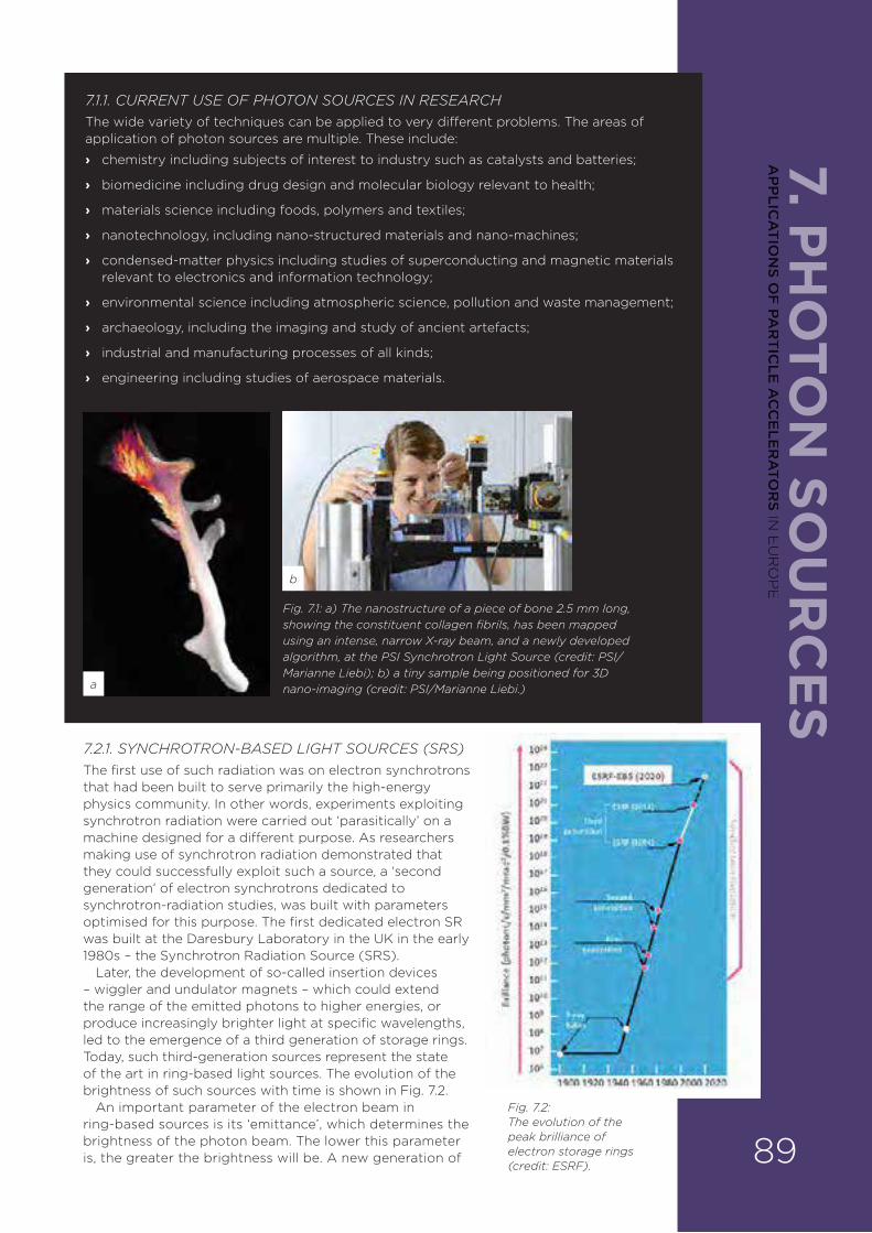
7. PH
OTO
N SO
UR
CE
S
7.2.1. SYNCHROTRON-BASED LIGHT SOURCES (SRS)The first use of such radiation was on electron synchrotrons that had been built to serve primarily the high-energy physics community. In other words, experiments exploiting synchrotron radiation were carried out ‘parasitically’ on a machine designed for a di¥erent purpose. As researchers making use of synchrotron radiation demonstrated that they could successfully exploit such a source, a ‘second generation’ of electron synchrotrons dedicated to synchrotron-radiation studies, was built with parameters optimised for this purpose. The first dedicated electron SR was built at the Daresbury Laboratory in the UK in the early 1980s – the Synchrotron Radiation Source (SRS).
Later, the development of so-called insertion devices – wiggler and undulator magnets – which could extend the range of the emitted photons to higher energies, or produce increasingly brighter light at specific wavelengths, led to the emergence of a third generation of storage rings. Today, such third-generation sources represent the state of the art in ring-based light sources. The evolution of the brightness of such sources with time is shown in Fig. 7.2.
An important parameter of the electron beam in ring-based sources is its ‘emittance’, which determines the brightness of the photon beam. The lower this parameter is, the greater the brightness will be. A new generation of
7.1.1. CURRENT USE OF PHOTON SOURCES IN RESEARCHThe wide variety of techniques can be applied to very di¥erent problems. The areas of application of photon sources are multiple. These include:
› chemistry including subjects of interest to industry such as catalysts and batteries;
› biomedicine including drug design and molecular biology relevant to health;
› materials science including foods, polymers and textiles;
› nanotechnology, including nano-structured materials and nano-machines;
› condensed-matter physics including studies of superconducting and magnetic materials relevant to electronics and information technology;
› environmental science including atmospheric science, pollution and waste management;
› archaeology, including the imaging and study of ancient artefacts;
› industrial and manufacturing processes of all kinds;
› engineering including studies of aerospace materials.
Fig. 7.1: a) The nanostructure of a piece of bone 2.5 mm long, showing the constituent collagen fibrils, has been mapped using an intense, narrow X-ray beam, and a newly developed algorithm, at the PSI Synchrotron Light Source (credit: PSI/Marianne Liebi); b) a tiny sample being positioned for 3D nano-imaging (credit: PSI/Marianne Liebi.)
Fig. 7.2: The evolution of the peak brilliance of electron storage rings (credit: ESRF).
a
b
89
AP
PLIC
AT
ION
S OF
PAR
TIC
LE A
CC
ELE
RA
TOR
S IN E
UR
OP
E
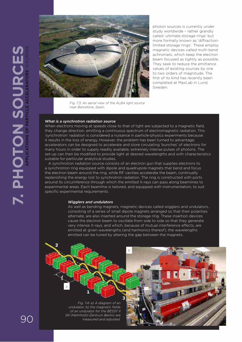
7. P
HO
TON
SO
UR
CE
S
What is a synchrotron radiation source When electrons moving at speeds close to that of light are subjected to a magnetic field, they change direction, emitting a continuous spectrum of electromagnetic radiation. This ‘synchrotron’ radiation is considered a nuisance in particle-physics experiments because it results in the loss of energy. However, the problem has been turned to advantage; accelerators can be designed to accelerate and store circulating ‘bunches’ of electrons for many hours in order to supply readily available, extremely intense pulses of photons. The set-up can then be modified to provide light at desired wavelengths and with characteristics suitable for particular analytical studies.
A synchrotron radiation source consists of an electron gun that supplies electrons to a synchrotron ring equipped with dipole and quadrupole magnets that bend and focus the electron beam around the ring, while RF cavities accelerate the beam, continually replenishing the energy lost to synchrotron radiation. The ring is constructed with ports around its circumference through which the emitted X-rays can pass along beamlines to experimental areas. Each beamline is tailored, and equipped with instrumentation, to suit specific experimental requirements.
photon sources is currently under study worldwide – rather grandly called ‘ultimate storage rings’ but more formally known as ‘di¥raction-limited storage rings’. These employ magnetic devices called multi-bend achromats, which keep the electron beam focused as tightly as possible. They seek to reduce the emittance values of existing sources by one to two orders of magnitude. The first of its kind has recently been completed at MaxLab in Lund, Sweden.
Fig. 7.4: a) A diagram of an undulator; b) the magnetic fields of an undulator for the BESSY II
SR (Helmholtz-Zentrum Berlin) are measured and adjusted.
Fig. 7.3: An aerial view of the ALBA light source near Barcelona, Spain.
Wigglers and undulatorsAs well as bending magnets, magnetic devices called wigglers and undulators, consisting of a series of small dipole magnets arranged so that their polarities alternate, are also inserted around the storage ring. These insertion devices cause the electron beam to oscillate from side to side so that they generate very intense X-rays, and which, because of mutual interference e¥ects, are emitted at given wavelengths (and harmonics thereof); the wavelengths emitted can be tuned by altering the gap between the magnets.
a
b
90
AP
PLI
CA
TIO
NS
OF
PA
RT
ICLE
AC
CE
LER
ATO
RS
IN E
UR
OP
E

7. PH
OTO
N SO
UR
CE
S7.2.2. LINAC-BASED LIGHT SOURCES. In recent decades, there have also been major advances in the development of light sources based on electrons accelerated in linacs. Linac-based light sources have an important advantage over storage rings in that the electron beam’s emittance is adiabatically damped during acceleration through the linac. This is in contrast to the situation in an SR where quantum excitation means that the emittance grows with the square of the beam energy. A linac-based source can thus provide an X-ray beam with a very high degree of coherence, a highly desirable feature for many for X-ray experiments.
Developments are centred on two main devices:
› the self-amplified spontaneous emission free electron laser (SASE-FEL);
› the energy recovery linac (ERL).
7.2.2.1. SASE FELSIn free electron lasers, an electron beam is accelerated in a linac, and passes through undulators to generate radiation. The wavelengths emitted are essentially dependent on the energy of the electron beam and the periodic arrangement of magnets in the undulator.
Fig. 7.5: The European XFEL at DESY in Hamburg, Germany. It runs from the DESY site in Hamburg to the research site in Schenefeld, Schleswig-Holstein
(credit: aerial view, FHH, Landesbetrieb Geoinf. und Vermessung).
Free electron lasers have been in existence for almost 40 years and come in di¥erent classes. In the early days of their development, they were restricted to mid-to-far-infrared operation in so-called oscillator mode: the generated radiation was allowed to interact repeatedly with the electron beam by being reflected back and forward in an optical cavity – to increase the intensity of the laser pulse. Although higher-energy electron beams could allow shorter wavelengths to be reached, the absence of mirrors of suitably high reflectivity in the VUV and X-ray region of the spectrum precluded this oscillator mode of operation at these wavelengths.
The development of the SASE concept, by which amplification of the radiation power is achieved after a single pass in a suitably long undulator, has made X-ray FELs a reality. 91
AP
PLIC
AT
ION
S OF
PAR
TIC
LE A
CC
ELE
RA
TOR
S IN E
UR
OP
E

7. P
HO
TON
SO
UR
CE
S
7.2.2.2. Energy recovery linacsEnergy recovery linacs (ERLs) are the most recent development, and are generating a lot of interest around the world because they combine the characteristics of an SR and a SASE FEL. An ERL is composed of a linac, which produces electron bunches having the required parameters for the radiation source. The linac is composed of a series of RF cavities which can either deliver or extract energy from the electron beam depending on the RF phase.
The electron beam is circulated in arcs, and is thus can be threaded back through the linac cavities at an appropriate phase so as to decelerate it and recover the energy not used to produce synchrotron radiation, thus making the system very e§cient. Superconducting linacs, in particular, can be highly e§cient due to their ability to store energy longer than normal conducting cavities. The ERL preserves the advantage of emittance reduction due to linac acceleration, while having the feature of an SR in that it can serve multiple user stations while the beam is being circulated in the arcs. Once the beam parameters have been diluted after several passages through the ERL, a ‘fresh’ beam can be accelerated in the linac to maintain the radiation quality. The diluted beam is then ‘dumped’ at a low energy after energy-recovery in the linac. A schematic of such a machine is shown in Fig. 7.7.
What is a SASE FELFree electron lasers o¥er a means of generating pulses of light a million times brighter than those from SRs by accelerating bunches of electrons injected into a linear accelerator. The electron beam is passed through an undulator, which causes the beam to oscillate and emit synchrotron radiation in intense, coherent bursts – as emitted from a typical pulsed laser. The wavelength of light can be tuned by altering the beam energy or the magnetic field of the undulator.
To amplify the light at longer wavelength FELs, mirrors placed at the ends of the linac bounce the light beam back and forth to increase interaction with the electron beam. However, to achieve enough gain at shorter wavelengths, the electron beam is sent down a much longer undulator consisting of several thousand magnets, and a process called self-amplified spontaneous emission (SASE) is exploited. The electrons in the bunches interact with the light emitted and, depending on the phase, they gain or lose energy resulting in the formation of dense ‘microbunches’. This modulation of the beam structure leads to the required rapid build-up of photons travelling in phase at selected energies.
Fig. 7.6: Extremely short and intense X-ray pulses are generated by the long undulator in a SASE FEL (credit: European XFEL/Marc Hermann).
What is an energy recovery linac (ERL)An ERL consists of a dual system composed of a powerful linac and a connecting loop around which insertion devices are installed. Electrons are released from the injector at the lower left in the figure opposite, and are accelerated in a long linear accelerator (main linac) in tightly confined bunches. After emerging from this linac, the electrons pass through the undulators, which ‘wiggle’ the electron beam to produce the X-rays in the usual way. Electrons are continuously injected, make one trip around the ring, and return to the main linac where their energy is recovered. The spent beam is directed to the dump.
Fig. 7.7: A schematic of the principle of the energy recovery linac (credit: Cornell University).92
AP
PLI
CA
TIO
NS
OF
PA
RT
ICLE
AC
CE
LER
ATO
RS
IN E
UR
OP
E

7. PH
OTO
N SO
UR
CE
SPhoton sources SR sources in EuropeThere are currently 12 synchrotron radiation facilities in Europe. The majority of these operate at medium energies (1.5 to 3 GeV); however, two of them (ESRF and Petra III) operate at a higher energy (6 GeV).
› ALBA (CELLS Laboratory, Barcelona, Spain)
› ANKA (Karlsruhe, Germany)
› BESSY-II (Berlin, Germany)
› DELTA (Dortmund, Germany)
› Diamond Light Source (Didcot, UK)
› Elettra (Trieste, Italy)
› European Synchrotron Radiation Source, ESRF (Grenoble, France)
› Max-IV (Max Laboratory, Lund, Sweden)
› Petra III (DESY, Hamburg, Germany)
› Swiss Light Source, SLS (PSI, Villigen, Switzerland)
› SOLARIS (Krakow, Poland)
› SOLEIL (Saint Aubin, France)
ERLsA number of prototype ERL facilities have been built on which to perform ERL research. Examples in Europe include BerlinPro (Helmholtz Center, Berlin) and ALICE (Daresbury, UK). A normal-conducting ERL is being developed at Novosibirsk in Russia. In the US, there is research at Brookhaven Laboratory (BNL ERL), Je¥erson Laboratory (SRF ERL) and Cornell (CLASSE). R&D is also carried out at the Japanese Atomic Energy Authority.
7.2.3. COMPTON SOURCESIn recent years, a new class of X-ray source has emerged based on the Compton scattering e¥ect. In this source, radiation from a conventional laser is backwards-scattered from an electron beam travelling in the opposite sense from the incident laser beam. The result is to produce radiation with orders of magnitude smaller wavelengths than that of the incident beam. Thus, an intense infrared (1 micrometre) laser backscattered from an electron beam of 50 MeV (one to two orders of magnitude less energy than the case of a typical storage ring) could produce around 40 keV photons. Although Compton sources cannot compete with SRs in providing light simultaneously to many beam lines, they have great potential as tuneable, intense, monochromatic sources for applications in medical and biomedical research. These, comparatively compact, sources provide the possibility of having intense hard X-rays available without the large infrastructure needed for an SR. Indeed, a commercial Compton source has been available since 2008 (from Lyncean Technologies in California, US).
The electron beam for a Compton source can be provided either by an electron linac or from a small SR. Increasingly advanced machines of this type are being developed around the globe, exploiting advances in laser, optical resonators and accelerator technology. Notable projects in Europe would include ThomX, under construction in Orsay (France) and based on a small SR, and ELI – an electron linac-based source under construction in Romania as part of the EU-funded ‘Extreme Light Infrastructure’ project.
Fig. 7.8: The photon energy and brightness relationship for a number of photon sources.
SASE FELs There are SASE FELS operating in Europe, the US and Japan, and others close to completion.
› E-XFEL, via an international collaboration (Hamburg, Germany)
› SwissFEL (PSI, Villigen, Switzerland)
› PAL-XFEL (Pohang Accelerator Laboratory, Pohang, Korea)
› FERMI (Trieste, Italy)
› Linac Coherent Light Source (Stanford, US)
› Spring-8 Angstrom Compact Free Electron Laser (SACLA, Riken, Japan)
› Other projects are in discussion around the globe.
93
AP
PLIC
AT
ION
S OF
PAR
TIC
LE A
CC
ELE
RA
TOR
S IN E
UR
OP
E

7. P
HO
TON
SO
UR
CE
S7.2.4. ADVANTAGES AND DISADVANTAGES OF THE DIFFERENT LIGHT SOURCES (SRS, SASE FELS AND ERLS)
› SRs can deliver a wide spectrum of electromagnetic radiation.
› SRs can serve multiple photon beamlines.
› SASE FELs can serve only a few experimental stations, as the electron beam is dumped after traversing the undulators.
› ERLs can serve multiple user stations.
› SASE FELs and ERLS can deliver X-rays that are more than one thousand million times brighter than those from synchrotron sources.
› SASE FELs and ERLS also deliver pulses of much shorter duration (femtoseconds) than for an SR (tens of picoseconds).
7.2.4.1. Advantages of accelerator-based photon sourcesA wide range of experimentsOne of the key aspects for all accelerator-based photon sources is the extremely high brilliance made available. The radiation is delivered in pulses and is also polarised. These characteristics allow a wide range of experiments to be carried out.
Materials characterisationThe photon beams generated can be used for materials characterisation – structural, electronic and magnetic at the scale of atoms and molecules, via various techniques:
› Di¥raction (analysis of the crystal structure of a wide range of materials including biological molecules and large-scale defects in engineering materials). It includes many variations such as powder di¥raction (for multi-crystalline materials), Laue (white-beam) di¥raction (small crystals) and small-angle scattering (larger-scale molecular systems).
› Absorption and emission spectroscopy.
› Photoemission studies.
› Infrared spectro-microscopy.
› Imaging/microscopy.
Synchrotron-based sources provide a broad photon spectrum that can be fine-tuned by proper choice of the insertion devices at each emission point (Fig. 7.8). This allows us to build beamlines optimised for very di¥erent parts of the electromagnetic spectrum – from infrared, through the UV and soft X-ray range, and up to the hard X-ray regime. Many of the techniques mentioned above can be targeted to di¥erent spectral ranges in specific beamlines, depending on the type of scientific problems under study.
Magnetism studiesAnother particular advantage is that the radiation emitted is polarised. The emission generated at SR dipole magnets has a natural linear polarisation in the plane of the orbit, while in the case of insertion devices, polarisation properties can be tuned to the needs of a beamline, in some cases with the possibility of switching between di¥erent polarisations. This can be used to obtain magnetic contrast in the above absorption, scattering and photoemission experiments.
DynamicsThe fact that synchrotron beams are pulsed allows time-resolved experiments for many of the techniques defined above. They o¥er the opportunity to follow atomic motions and reactions in exquisite detail.
For third-generation SRs, the typical duration of a pulse is at the level of tens of picoseconds, with an interval between consecutive pulses at the nanosecond level. In order to obtain su§cient statistics on the dynamical changes in a sample, the 94
AP
PLI
CA
TIO
NS
OF
PA
RT
ICLE
AC
CE
LER
ATO
RS
IN E
UR
OP
E
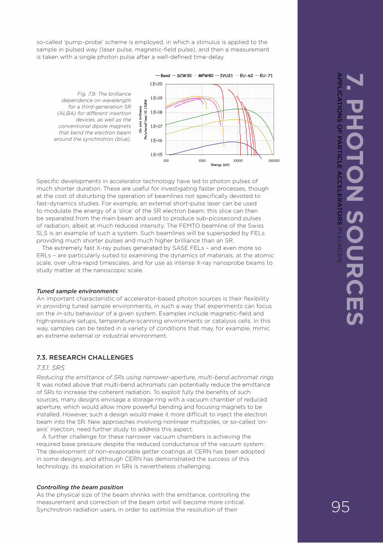
7. PH
OTO
N SO
UR
CE
Sso-called ‘pump–probe’ scheme is employed, in which a stimulus is applied to the sample in pulsed way (laser pulse, magnetic-field pulse), and then a measurement is taken with a single photon pulse after a well-defined time-delay.
Fig. 7.9: The brilliance dependence on wavelength
for a third-generation SR (ALBA) for di�erent insertion
devices, as well as the conventional dipole magnets that bend the electron beam
around the synchrotron (blue).
Specific developments in accelerator technology have led to photon pulses of much shorter duration. These are useful for investigating faster processes, though at the cost of disturbing the operation of beamlines not specifically devoted to fast-dynamics studies. For example, an external short-pulse laser can be used to modulate the energy of a ‘slice’ of the SR electron beam; this slice can then be separated from the main beam and used to produce sub-picosecond pulses of radiation, albeit at much reduced intensity. The FEMTO beamline of the Swiss SLS is an example of such a system. Such beamlines will be superseded by FELs providing much shorter pulses and much higher brilliance than an SR.
The extremely fast X-ray pulses generated by SASE FELs – and even more so ERLs – are particularly suited to examining the dynamics of materials, at the atomic scale, over ultra-rapid timescales, and for use as intense X-ray nanoprobe beams to study matter at the nanoscopic scale.
Tuned sample environments An important characteristic of accelerator-based photon sources is their flexibility in providing tuned sample environments, in such a way that experiments can focus on the in-situ behaviour of a given system. Examples include magnetic-field and high-pressure setups, temperature-scanning environments or catalysis cells. In this way, samples can be tested in a variety of conditions that may, for example, mimic an extreme external or industrial environment.
7.3. RESEARCH CHALLENGES7.3.1. SRSReducing the emittance of SRs using narrower-aperture, multi-bend achromat rings It was noted above that multi-bend achromats can potentially reduce the emittance of SRs to increase the coherent radiation. To exploit fully the benefits of such sources, many designs envisage a storage ring with a vacuum chamber of reduced aperture, which would allow more powerful bending and focusing magnets to be installed. However, such a design would make it more di§cult to inject the electron beam into the SR. New approaches involving nonlinear multipoles, or so-called ‘on-axis’ injection, need further study to address this aspect.
A further challenge for these narrower vacuum chambers is achieving the required base pressure despite the reduced conductance of the vacuum system. The development of non-evaporable getter coatings at CERN has been adopted in some designs, and although CERN has demonstrated the success of this technology, its exploitation in SRs is nevertheless challenging.
Controlling the beam positionAs the physical size of the beam shrinks with the emittance, controlling the measurement and correction of the beam orbit will become more critical. Synchrotron radiation users, in order to optimise the resolution of their 95
AP
PLIC
AT
ION
S OF
PAR
TIC
LE A
CC
ELE
RA
TOR
S IN E
UR
OP
E
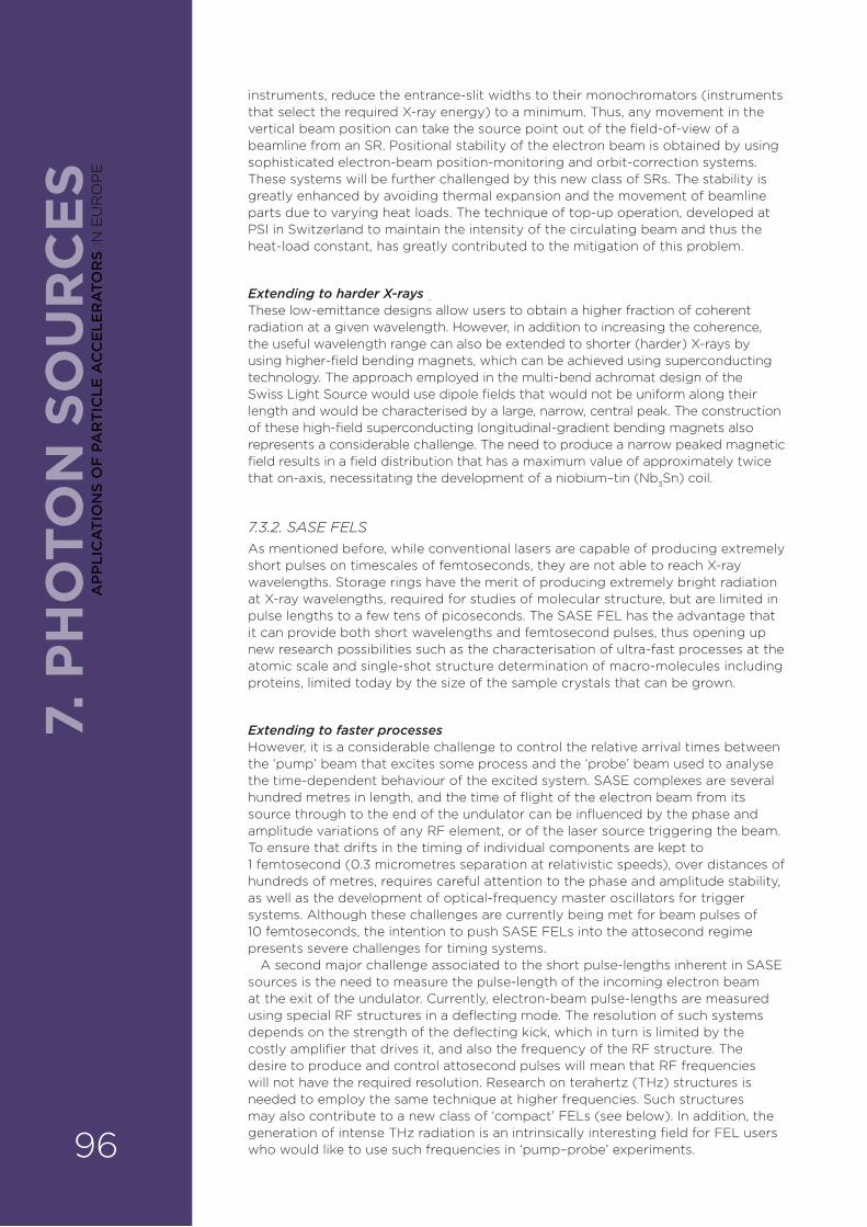
7. P
HO
TON
SO
UR
CE
Sinstruments, reduce the entrance-slit widths to their monochromators (instruments that select the required X-ray energy) to a minimum. Thus, any movement in the vertical beam position can take the source point out of the field-of-view of a beamline from an SR. Positional stability of the electron beam is obtained by using sophisticated electron-beam position-monitoring and orbit-correction systems. These systems will be further challenged by this new class of SRs. The stability is greatly enhanced by avoiding thermal expansion and the movement of beamline parts due to varying heat loads. The technique of top-up operation, developed at PSI in Switzerland to maintain the intensity of the circulating beam and thus the heat-load constant, has greatly contributed to the mitigation of this problem.
Extending to harder X-rays These low-emittance designs allow users to obtain a higher fraction of coherent radiation at a given wavelength. However, in addition to increasing the coherence, the useful wavelength range can also be extended to shorter (harder) X-rays by using higher-field bending magnets, which can be achieved using superconducting technology. The approach employed in the multi-bend achromat design of the Swiss Light Source would use dipole fields that would not be uniform along their length and would be characterised by a large, narrow, central peak. The construction of these high-field superconducting longitudinal-gradient bending magnets also represents a considerable challenge. The need to produce a narrow peaked magnetic field results in a field distribution that has a maximum value of approximately twice that on-axis, necessitating the development of a niobium–tin (Nb3Sn) coil.
7.3.2. SASE FELSAs mentioned before, while conventional lasers are capable of producing extremely short pulses on timescales of femtoseconds, they are not able to reach X-ray wavelengths. Storage rings have the merit of producing extremely bright radiation at X-ray wavelengths, required for studies of molecular structure, but are limited in pulse lengths to a few tens of picoseconds. The SASE FEL has the advantage that it can provide both short wavelengths and femtosecond pulses, thus opening up new research possibilities such as the characterisation of ultra-fast processes at the atomic scale and single-shot structure determination of macro-molecules including proteins, limited today by the size of the sample crystals that can be grown.
Extending to faster processesHowever, it is a considerable challenge to control the relative arrival times between the ‘pump’ beam that excites some process and the ‘probe’ beam used to analyse the time-dependent behaviour of the excited system. SASE complexes are several hundred metres in length, and the time of flight of the electron beam from its source through to the end of the undulator can be influenced by the phase and amplitude variations of any RF element, or of the laser source triggering the beam. To ensure that drifts in the timing of individual components are kept to 1 femtosecond (0.3 micrometres separation at relativistic speeds), over distances of hundreds of metres, requires careful attention to the phase and amplitude stability, as well as the development of optical-frequency master oscillators for trigger systems. Although these challenges are currently being met for beam pulses of 10 femtoseconds, the intention to push SASE FELs into the attosecond regime presents severe challenges for timing systems.
A second major challenge associated to the short pulse-lengths inherent in SASE sources is the need to measure the pulse-length of the incoming electron beam at the exit of the undulator. Currently, electron-beam pulse-lengths are measured using special RF structures in a deflecting mode. The resolution of such systems depends on the strength of the deflecting kick, which in turn is limited by the costly amplifier that drives it, and also the frequency of the RF structure. The desire to produce and control attosecond pulses will mean that RF frequencies will not have the required resolution. Research on terahertz (THz) structures is needed to employ the same technique at higher frequencies. Such structures may also contribute to a new class of ‘compact’ FELs (see below). In addition, the generation of intense THz radiation is an intrinsically interesting field for FEL users who would like to use such frequencies in ‘pump–probe’ experiments. 96
AP
PLI
CA
TIO
NS
OF
PA
RT
ICLE
AC
CE
LER
ATO
RS
IN E
UR
OP
E
7. PH
OTO
N SO
UR
CE
SA tunable seed sourcePerhaps the most important research topic on FELs today is ‘seeding’. SASE FELs, by their nature, exhibit wavelength and amplitude fluctuations from shot to shot. These fluctuations can be reduced substantially, and the longitudinal coherence of the FEL pulse greatly improved, if the pulse can be seeded with an external signal, such as a laser operating at the FEL resonant wavelength, rather than allowing the signal to grow from the white noise of the spontaneous emission. As the principal advantage of the FEL is its tunability, it is necessary to provide a seed source which is also tunable. Seeding by conventional laser and by high-harmonic generation has been demonstrated at VUV wavelengths, but much work is still needed to operate seeding routinely at shorter wavelengths.
7.3.3. ERLS There are a number of problems being treated at the ERL prototypes that are currently being developed; some are indicated below.
› Much of the R&D on ERLs is concerned with the problems of generating and conserving low-emittance beams.
› Improved photocathode materials for electron-beam generation would be highly beneficial.
› Advances in RF technology, in particular, power couplers for superconducting cavities, are needed for high-power beam generation.
› Handling the problem of excitation of resonant modes in the RF cavities by the electron beam is needed to prevent these modes subsequently limiting the electron-beam current.
7.4. OTHER CHALLENGESAdequate capacity for researchStorage rings are normally operated within large national laboratories, whereas the users who exploit them come from academic institutes often far and wide. The allocation of beam-time on a given beamline is based on the scientific excellence of the experiment proposed by the users, which is evaluated by committees of experts. Despite the large number of existing sources in Europe, North America, Asia and elsewhere, it is generally recognised that the demand for beam-time on such machines exceeds the available supply by a factor of close to three. Thus, the competition for access is extremely strong. Providing su§cient ‘capacity’ therefore represents a significant challenge for the scientific community.
Improving reliabilityAs users are given a limited allocation of time on a beamline, it is extremely important to them that the machine performs reliably during the period allocated. Thus, reliability represents a serious technical challenge for the engineers and technicians who maintain and operate an SR. Such machines operate for typically about 200 days per year in blocks of several weeks, 24 hours a day. Machine failures lasting one or two days, or even a few hours, can have severe consequences on the success of a given experiment – and a loss of credibility, particularly where ‘commercial’ users, who pay for beam-time, are concerned. The reliability of modern SRs is typically 98 to 99 per cent (defined as the ratio of operating time to scheduled time). To maintain these high values requires many technical systems, which in turn must also be highly reliable – not operating too close to their technical limits (that is, with su§cient redundancy). In the case when a failure does occur, it is important to be able to react swiftly to reduce the ‘down-time’ of the beam, necessitating on-call service personnel and a su§cient availability of spare parts. In today’s third-generation sources, with literally hundreds of technical subsystems, the mean time between failures can exceed 150 hours.
97
AP
PLIC
AT
ION
S OF
PAR
TIC
LE A
CC
ELE
RA
TOR
S IN E
UR
OP
E
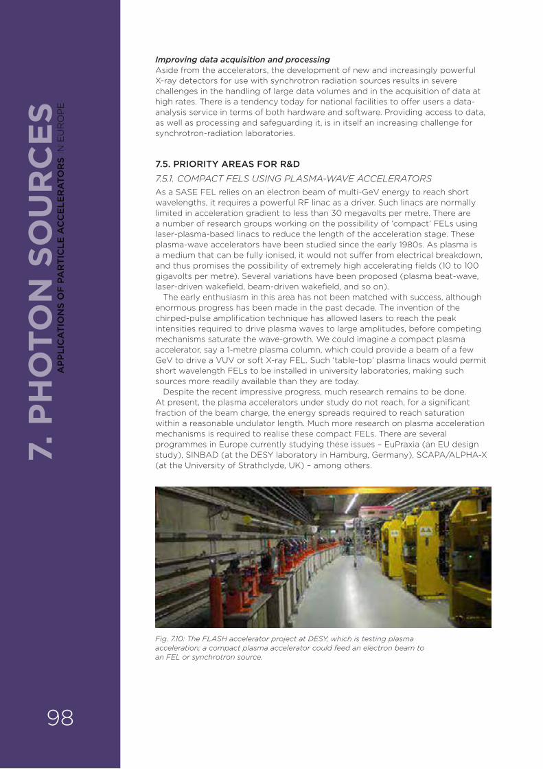
7. P
HO
TON
SO
UR
CE
SImproving data acquisition and processingAside from the accelerators, the development of new and increasingly powerful X-ray detectors for use with synchrotron radiation sources results in severe challenges in the handling of large data volumes and in the acquisition of data at high rates. There is a tendency today for national facilities to o¥er users a data-analysis service in terms of both hardware and software. Providing access to data, as well as processing and safeguarding it, is in itself an increasing challenge for synchrotron-radiation laboratories.
7.5. PRIORITY AREAS FOR R&D7.5.1. COMPACT FELS USING PLASMA-WAVE ACCELERATORSAs a SASE FEL relies on an electron beam of multi-GeV energy to reach short wavelengths, it requires a powerful RF linac as a driver. Such linacs are normally limited in acceleration gradient to less than 30 megavolts per metre. There are a number of research groups working on the possibility of ‘compact’ FELs using laser-plasma-based linacs to reduce the length of the acceleration stage. These plasma-wave accelerators have been studied since the early 1980s. As plasma is a medium that can be fully ionised, it would not su¥er from electrical breakdown, and thus promises the possibility of extremely high accelerating fields (10 to 100 gigavolts per metre). Several variations have been proposed (plasma beat-wave, laser-driven wakefield, beam-driven wakefield, and so on).
The early enthusiasm in this area has not been matched with success, although enormous progress has been made in the past decade. The invention of the chirped-pulse amplification technique has allowed lasers to reach the peak intensities required to drive plasma waves to large amplitudes, before competing mechanisms saturate the wave-growth. We could imagine a compact plasma accelerator, say a 1-metre plasma column, which could provide a beam of a few GeV to drive a VUV or soft X-ray FEL. Such ‘table-top’ plasma linacs would permit short wavelength FELs to be installed in university laboratories, making such sources more readily available than they are today.
Despite the recent impressive progress, much research remains to be done. At present, the plasma accelerators under study do not reach, for a significant fraction of the beam charge, the energy spreads required to reach saturation within a reasonable undulator length. Much more research on plasma acceleration mechanisms is required to realise these compact FELs. There are several programmes in Europe currently studying these issues – EuPraxia (an EU design study), SINBAD (at the DESY laboratory in Hamburg, Germany), SCAPA/ALPHA-X (at the University of Strathclyde, UK) – among others.
Fig. 7.10: The FLASH accelerator project at DESY, which is testing plasma acceleration; a compact plasma accelerator could feed an electron beam to an FEL or synchrotron source.
98
AP
PLI
CA
TIO
NS
OF
PA
RT
ICLE
AC
CE
LER
ATO
RS
IN E
UR
OP
E

7. PH
OTO
N SO
UR
CE
S7.5.2. ACCELERATOR ON A CHIPIt should also be noted that the use of miniature dielectric structures for acceleration is emerging as a competitor to plasma structures for laser-driven acceleration. Experiments, operating on the millimetre-to-micrometre scale, have demonstrated the very high acceleration gradients for electrons travelling down minute dielectric channels. However, much more research is needed to investigate if such structures could eventually be used for acceleration, and to determine the quality of beams that they could provide. Currently, a large international collaboration, ACHIP (Acceleration on a CHIP), is addressing this problem.
Fig. 7.11: Nano-fabricated silica chips can be used to accelerate electrons at 10 times the rate of a conventional accelerator (credit: SLAC).
7.6. IMPACT ON INDUSTRY AND EDUCATION7.6.1. INDUSTRYR&D collaboration with industry The construction and operation of high-brightness light sources have a significant impact on industry. It is evident, of course, that SRs and their injection complexes require sophisticated engineering and technical systems in the areas of power supply, magnets, vacuum systems, RF systems, control systems, instrumentation, cryogenics, superconducting materials, optical components and lasers, to name but a few. Many of the required products are not readily commercially available, because light sources often need custom-built components specified by the SR designers. Thus, strong collaboration with industry is required in the development and production of these components.
Industry’s interest in particle accelerators is evident from its strong presence at conferences on accelerators. While some industries collaborate with accelerator laboratories because the products they produce for other communities (medical, communication, and so on) provide them with the required competence, there are other companies whose principal activity is centred on the direct needs of the accelerator community. Indeed, the development of linac-based, 4th-generation light sources has required some industries – in collaboration with research laboratories – to commit to developing and producing superconducting accelerating structures, previously unavailable. Other examples include the development of new high-e§ciency, high-power vacuum electronic RF amplifiers (klystrons), of interest uniquely to the accelerator community. Of course, there is a strong incentive for laboratories hosting SRs to comply with industry standards in order to reduce costs and ensure the long-term availability of spare parts.
Commercial developmentLaboratories that operate SRs have in recent years become increasingly aware of the concepts of technology-transfer and knowledge-exchange, and so often seek industrial partners to commercialise their ideas and enable new products to appear on the market. A notable success in the past decade is the pioneering work done by the RF research group at the SOLEIL light source (France) on the development of solid-state RF power amplifiers, which can now be purchased commercially. Recent years have also seen the emergence of companies providing turn-key systems for light sources. Examples include Research Instruments in Bergisch Gladbach, Germany (injector linacs), Libera in Solkan, Slovenia (beam-position monitors), Dectris in Baden-Dättwil, Switzerland (photon detectors), and Cosylab in Ljubljana, Slovenia (accelerator control systems).
99
AP
PLIC
AT
ION
S OF
PAR
TIC
LE A
CC
ELE
RA
TOR
S IN E
UR
OP
E
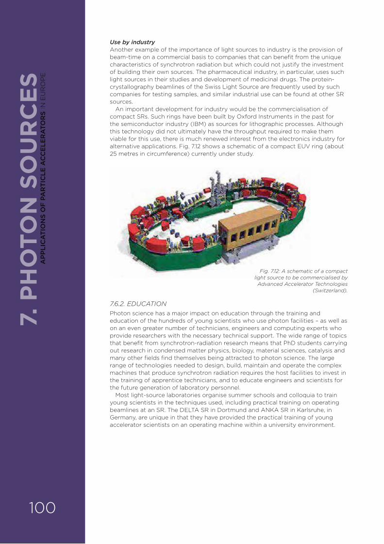
7. P
HO
TON
SO
UR
CE
SUse by industryAnother example of the importance of light sources to industry is the provision of beam-time on a commercial basis to companies that can benefit from the unique characteristics of synchrotron radiation but which could not justify the investment of building their own sources. The pharmaceutical industry, in particular, uses such light sources in their studies and development of medicinal drugs. The protein-crystallography beamlines of the Swiss Light Source are frequently used by such companies for testing samples, and similar industrial use can be found at other SR sources.
An important development for industry would be the commercialisation of compact SRs. Such rings have been built by Oxford Instruments in the past for the semiconductor industry (IBM) as sources for lithographic processes. Although this technology did not ultimately have the throughput required to make them viable for this use, there is much renewed interest from the electronics industry for alternative applications. Fig. 7.12 shows a schematic of a compact EUV ring (about 25 metres in circumference) currently under study.
7.6.2. EDUCATIONPhoton science has a major impact on education through the training and education of the hundreds of young scientists who use photon facilities – as well as on an even greater number of technicians, engineers and computing experts who provide researchers with the necessary technical support. The wide range of topics that benefit from synchrotron-radiation research means that PhD students carrying out research in condensed matter physics, biology, material sciences, catalysis and many other fields find themselves being attracted to photon science. The large range of technologies needed to design, build, maintain and operate the complex machines that produce synchrotron radiation requires the host facilities to invest in the training of apprentice technicians, and to educate engineers and scientists for the future generation of laboratory personnel.
Most light-source laboratories organise summer schools and colloquia to train young scientists in the techniques used, including practical training on operating beamlines at an SR. The DELTA SR in Dortmund and ANKA SR in Karlsruhe, in Germany, are unique in that they have provided the practical training of young accelerator scientists on an operating machine within a university environment.
Fig. 7.12: A schematic of a compact light source to be commercialised by Advanced Accelerator Technologies
(Switzerland).
100
AP
PLI
CA
TIO
NS
OF
PA
RT
ICLE
AC
CE
LER
ATO
RS
IN E
UR
OP
E
7. PH
OTO
N SO
UR
CE
S7.7. KEY RECOMMENDATIONS FOR APPLICATIONS OF PARTICLE ACCELERATORS TO PHOTON SOURCES
Accelerator-based photon sources have developed enormously over the past 50 years. If this pace of development is to continue, then it will be important to continue R&D in many of the disciplines of accelerator physics. Quite apart from the R&D required in more exotic areas such as laser-plasma acceleration, many of the more ‘traditional’ technologies would benefit from further development. These include the following:
› High-brightness electron guns with a high repetition rate are needed (for longer duty-cycle FELs).
› The development of superconducting cavities with strong higher-order-mode damping will be needed for ERLs to operate at high current without su©ering from instabilities.
› Improved modelling and simulation of low-emittance electron-beam transport from the source through to the undulator are needed to enable the design of linac-based sources to be improved.
› improvements of undulators operating in-vacuum, and of superconducting undulators with shorter period lengths than those available today, would be highly beneficial for both circular and linear machines.
› The development of new RF power sources will be needed as electronic vacuum tubes disappear from the market.
If such developments are to be possible, it will be necessary for laboratories operating synchrotron-radiation sources to continue to invest in healthy accelerator physics R&D programmes. Cooperation between these laboratories is also important. The European SR community already meets annually to share operational experience of its facilities and to discuss new developments in the field. Many laboratories already collaborate through programmes funded by the EU. Stronger collaboration is recommended, as this can only be beneficial for all concerned. At the time of writing, the synchrotron radiation community has formed the LEAPS collaboration to seek further support from the EU.
101
AP
PLIC
AT
ION
S OF
PAR
TIC
LE A
CC
ELE
RA
TOR
S IN E
UR
OP
E
NEUTRON BEAMS ARE A KEY TOOL IN BOTH BASIC AND INDUSTRIAL SCIENTIFIC RESEARCH. THERE IS AN IMPENDING DEFICIT IN THE AVAILABILITY OF SUITABLE NEUTRON SOURCES IN EUROPE, TOGETHER WITH AN INCREASED DEMAND FOR MORE INTENSE BEAMS. A RANGE OF NEUTRON SOURCES BASED ON ADVANCED ACCELERATOR SYSTEMS NEEDS TO BE DEVELOPED URGENTLY TO MEET THESE NEEDS.
Mats Lindroos, Pierfrancesco Mastinu, Mike Seidel, Eugene Tanke and John Thomason
8.1. INTRODUCTIONNeutrons, the electrically neutral constituents of the atomic nucleus, can be generated in nuclear reactions using accelerators. As has already been explained in previous chapters, such neutron sources are used in cancer therapy (Chapter 3), and are a significant component of future schemes to provide safer nuclear energy through accelerator-driven transmutation and power generation (Chapter 5). They are also an important tool in gathering measurement data needed for studies in fundamental and nuclear physics.
However, neutron sources have another essential role, without which research in many scientific disciplines would not have progressed. Like X-rays, neutrons can be used to probe the structure and properties of matter at the atomic and molecular scale. When a beam of neutrons passes through a material, they are reflected by the nuclei of the constituent atoms. Because they behave as waves as well as particles, they produce a characteristic scattering pattern resulting from the di¥raction of the reflected neutron waves. This pattern uncovers the location and behaviour of the atoms, so that a picture can be built up of the material’s internal microscopic structure. Furthermore, since neutrons have a magnetic moment, they can reveal the magnetic properties as well – an application relevant to the electronics industry. Not only can neutrons image the static structure, but – by measuring energy changes in the neutron beams before and after scattering – they can probe electronic excitations, and atomic and molecular motions, which thus give a precise picture of a material’s dynamic behaviour and properties.
Neutron scattering is often used alongside X-ray studies in a complementary way. Neutrons are more penetrating than X-rays, and they also more easily ‘see’ the positions of lighter atoms like hydrogen (a particularly significant advantage in molecular biology studies). However, they do not provide as much atomic detail, since current neutron beams are not as intense as the X-ray beams available today. Nevertheless, neutron scattering is extremely versatile and finds application in virtually all scientific research areas (see opposite). It is expected to play an ever-increasing role in biomedical, advanced materials and electronics research. However, this will require parallel progress in developing state-of-the-art accelerator technology.
8. N
EU
TRO
N S
OU
RC
ES
Mats Lindroos, ESS, Lund, Sweden.
Pierfrancesco Mastinu, LNL-INFN, Legnaro,
Italy.
Mike Seidel, PSI, Villigen, Switzerland.
Eugene Tanke, ESS, Lund, Sweden.
John Thomason, ISIS, Harwell, UK.
8. ACCELERATORS AND NEUTRON SOURCES
102
AP
PLI
CA
TIO
NS
OF
PA
RT
ICLE
AC
CE
LER
ATO
RS
IN E
UR
OP
E

8.1.2. APPLICATIONS OF NEUTRON SCATTERING
› Engineering: neutrons are used to image deep into solid objects to investigate their structure and strength, and to look at stresses that may impact the lifetimes of engineering components; examples include pipelines, turbine blades, train wheels and welds.
› Chemistry: neutrons are used to study chemical reactions of importance for the pharmaceutical, food and medical industries.
› IT and computing: neutrons are being used for materials studies to improve data storage and transmission.
› Magnetism: neutrons can probe complex magnetic structures and superconducting materials of significance to the electronics industry.
› Materials science: neutrons are used to determine the molecular structure of both crystals and dis-ordered materials, including liquids and gases, for many applications, particularly in industry.
› Polymers and soft matter: neutrons have been used to study the structure of polymers for many years and are now providing detailed dynamic studies of polymer films, and complex fluids such as cleaning materials, foods and personal-care products.
8. NE
UTR
ON
SOU
RC
ES
Fig. 8.1: Neutron inelastic scattering measurements can be used to investigate the exotic magnetic structures of metal compounds – here, the spinel, iron scandium sulfide (FeSc2S4) – that throw light on physics that could lead to novel electronic devices (credit: PSI/A. Bi�en et al., Phys.Rev.Lett., 2017, 118, 067205).
Fig. 8.2: The Ines di�ractometer at the ISIS spallation neutron source (UK) was able to reveal the microscopic internal structure of prostate stones found within a 12,000-year-old skeleton at an ancient burial site in the Sudan (credit: D. Usai et al.).
› Molecular biology and medical science: neutrons can uncover study the arrangement of water molecules in biological systems, the structure of proteins and other large molecules relevant to disease, and even the behaviour of large biomolecular assemblies such as cell membranes, which may be significant in understanding the uptake of drugs by the body.
› The environment: neutrons are employed in a wide variety of studies concerning pollution, climate change, agriculture and green energy.
› Cultural heritage: the non-destructive nature of neutron techniques (scattering and transmission) means they can be used to determine the composition and internal structure of antiquities and art objects.
103
AP
PLIC
AT
ION
S OF
PAR
TIC
LE A
CC
ELE
RA
TOR
S IN E
UR
OP
E
8.2. STATE OF THE ARTThere are two main sources of neutrons for scattering measurements:
› research reactors;
› particle accelerators.
8.2.1. NEUTRONS FROM RESEARCH REACTORSIn a research reactor, typically two to three neutrons are produced by the fission of one uranium atom and they have traditionally been the major source of neutrons for research. However, they require the handling of fissile material, which is potentially a major constraint for both licensing and disposal.
8.2.2. NEUTRONS FROM PARTICLE ACCELERATORSParticle accelerators are used to produce neutrons via spallation (Fig. 8.3). This is a nuclear process in which neutrons at di¥erent energies are emitted in several stages following the bombardment of heavy nuclei in a target with highly energetic particles, generally protons. The energy of the neutrons is reduced to useful ranges using moderators, and they are delivered to the measuring instruments via neutron guides. Typically, more than 30 neutrons can be produced in the spallation of a heavy element such as tungsten by an energetic proton. Noteworthy here is that the heat produced in spallation is about one-tenth of that produced in a reactor.
The spallation process is the most practical and feasible way of producing neutrons for a reasonable amount of e¥ort (or simply cost) of the neutron-source cooling system. It is generally agreed that a proton energy between 0.5 and 3 GeV is optimal for this. The sources come in three basic types: short-pulse sources (with pulses lasting a few microseconds), long-pulse sources (pulses lasting a few milliseconds) and continuous sources. In general, synchrotrons or accumulator (compressor) rings are used to drive short neutron pulses, while linear accelerators are used to drive long neutron pulses, and cyclotrons are used to drive continuous beams of neutrons. Fig. 8.4 shows the instantaneous neutron flux at most of the world facilities, both for pulsed and for continuous beam (steady-state) sources, as a function of the year of their completion.
8.3. CURRENT USAGE OF NEUTRON SOURCESBetween 5000 to 6000 researchers, across Europe, currently use neutrons as their primary tool for research. Many of these users work at neutron facilities that depend on research reactors. However, a majority of these reactors will be phased out over the next decade. The remaining neutron sources, which should support this community, will be the two spallation sources – ISIS in Harwell Oxford, UK and SINQ at the Paul Scherrer Institute (PSI) in Villigen, Switzerland – together with the research reactors at the Institut Laue–Langevin (ILL) in Grenoble, France and FRM-II in Munich, Germany.
A new, much more powerful spallation source, the European Spallation Source (ESS) is under construction in Lund, Sweden, and will come into full user operation in 2023. The ESS will accelerate a high current (62.5 mA) beam of protons up to 2 GeV in a sequence of normal-conducting and superconducting accelerating structures in the ESS linac. Both the normal-conducting structures (RF-quadrupole and drift-tube linac) and the superconducting structures operate in a pulsed mode. The proton beam, which will have a beam power of 5 MW, is then transported to a target, where a high flux of pulsed spallation neutrons will be produced.
Even taking the ESS into account, there will be a large shortfall of neutrons to serve the European research community, so plans need to be made for additional sources, for example, upgrades or replacements for existing facilities, and new cheaper, compact sources.
8. N
EU
TRO
N S
OU
RC
ES
104
AP
PLI
CA
TIO
NS
OF
PA
RT
ICLE
AC
CE
LER
ATO
RS
IN E
UR
OP
E
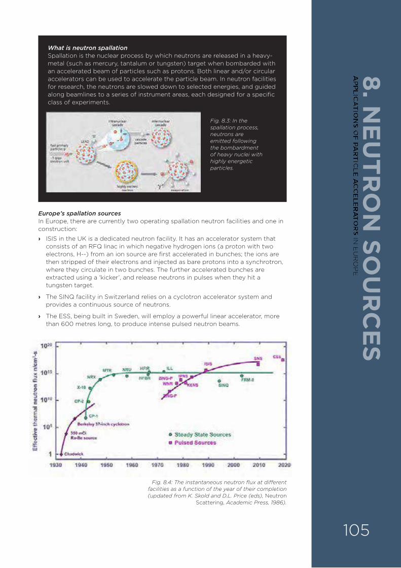
8. NE
UTR
ON
SOU
RC
ES
Europe’s spallation sourcesIn Europe, there are currently two operating spallation neutron facilities and one in construction:
› ISIS in the UK is a dedicated neutron facility. It has an accelerator system that consists of an RFQ linac in which negative hydrogen ions (a proton with two electrons, H--) from an ion source are first accelerated in bunches; the ions are then stripped of their electrons and injected as bare protons into a synchrotron, where they circulate in two bunches. The further accelerated bunches are extracted using a ‘kicker’, and release neutrons in pulses when they hit a tungsten target.
› The SINQ facility in Switzerland relies on a cyclotron accelerator system and provides a continuous source of neutrons.
› The ESS, being built in Sweden, will employ a powerful linear accelerator, more than 600 metres long, to produce intense pulsed neutron beams.
What is neutron spallationSpallation is the nuclear process by which neutrons are released in a heavy-metal (such as mercury, tantalum or tungsten) target when bombarded with an accelerated beam of particles such as protons. Both linear and/or circular accelerators can be used to accelerate the particle beam. In neutron facilities for research, the neutrons are slowed down to selected energies, and guided along beamlines to a series of instrument areas, each designed for a specific class of experiments.
Fig. 8.3: In the spallation process, neutrons are emitted following the bombardment of heavy nuclei with highly energetic particles.
Fig. 8.4: The instantaneous neutron flux at di�erent facilities as a function of the year of their completion (updated from K. Skold and D.L. Price (eds), Neutron
Scattering, Academic Press, 1986).
105
AP
PLIC
AT
ION
S OF
PAR
TIC
LE A
CC
ELE
RA
TOR
S IN E
UR
OP
E
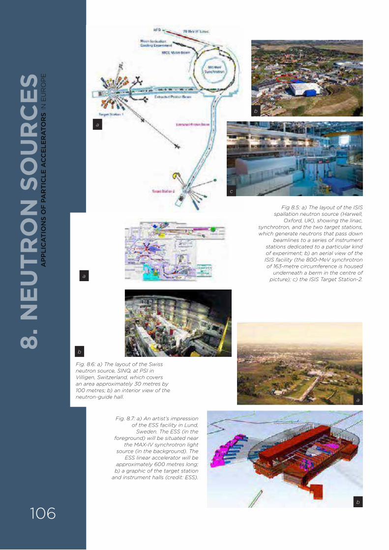
Fig 8.5: a) The layout of the ISIS spallation neutron source (Harwell,
Oxford, UK), showing the linac, synchrotron, and the two target stations, which generate neutrons that pass down
beamlines to a series of instrument stations dedicated to a particular kind of experiment; b) an aerial view of the ISIS facility (the 800-MeV synchrotron of 163-metre circumference is housed
underneath a berm in the centre of picture); c) the ISIS Target Station-2.
Fig. 8.6: a) The layout of the Swiss neutron source, SINQ, at PSI in Villigen, Switzerland, which covers an area approximately 30 metres by 100 metres; b) an interior view of the neutron-guide hall.
Fig. 8.7: a) An artist’s impression of the ESS facility in Lund,
Sweden. The ESS (in the foreground) will be situated near
the MAX-IV synchrotron light source (in the background). The
ESS linear accelerator will be approximately 600 metres long; b) a graphic of the target station
and instrument halls (credit: ESS).
8. N
EU
TRO
N S
OU
RC
ES
a
b
c
a
a
b
b
106
AP
PLI
CA
TIO
NS
OF
PA
RT
ICLE
AC
CE
LER
ATO
RS
IN E
UR
OP
E
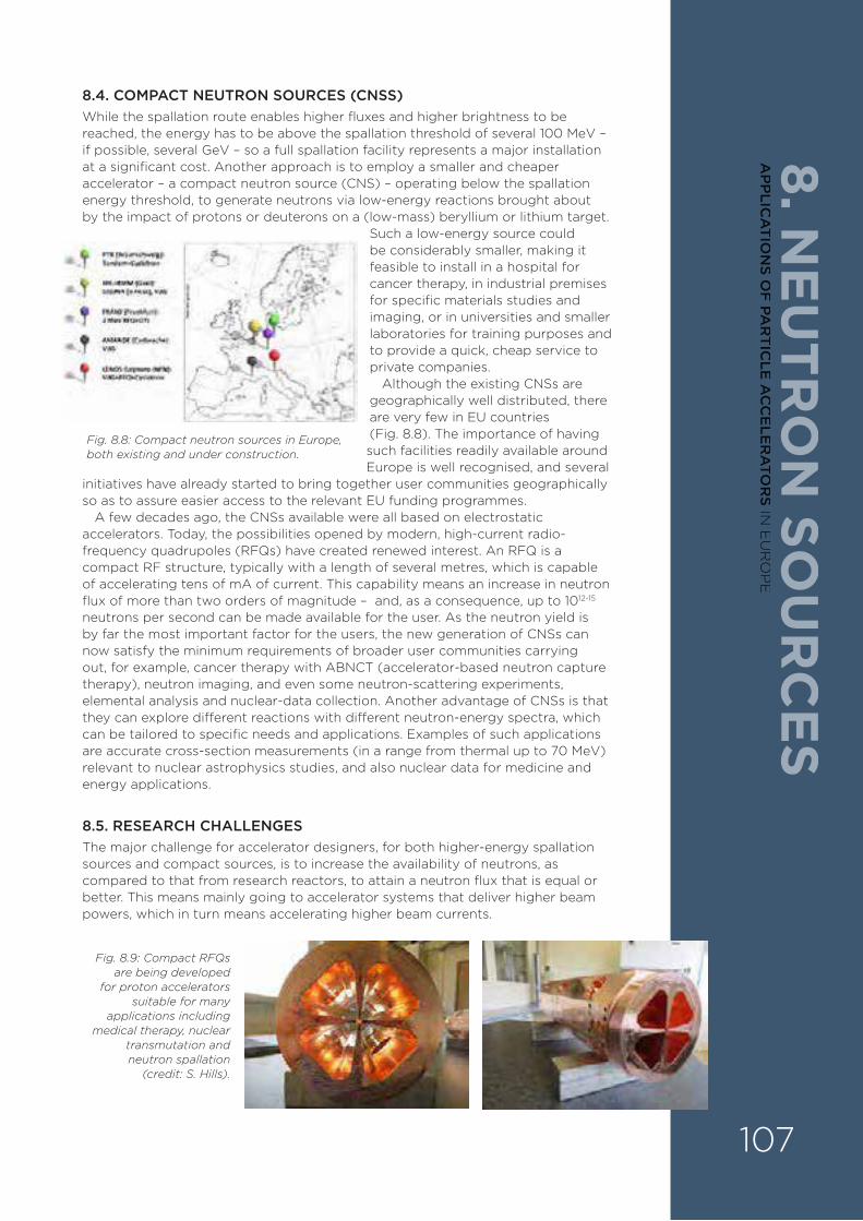
8. NE
UTR
ON
SOU
RC
ES
8.4. COMPACT NEUTRON SOURCES (CNSS)While the spallation route enables higher fluxes and higher brightness to be reached, the energy has to be above the spallation threshold of several 100 MeV – if possible, several GeV – so a full spallation facility represents a major installation at a significant cost. Another approach is to employ a smaller and cheaper accelerator – a compact neutron source (CNS) – operating below the spallation energy threshold, to generate neutrons via low-energy reactions brought about by the impact of protons or deuterons on a (low-mass) beryllium or lithium target.
Such a low-energy source could be considerably smaller, making it feasible to install in a hospital for cancer therapy, in industrial premises for specific materials studies and imaging, or in universities and smaller laboratories for training purposes and to provide a quick, cheap service to private companies.
Although the existing CNSs are geographically well distributed, there are very few in EU countries (Fig. 8.8). The importance of having such facilities readily available around Europe is well recognised, and several
initiatives have already started to bring together user communities geographically so as to assure easier access to the relevant EU funding programmes.
A few decades ago, the CNSs available were all based on electrostatic accelerators. Today, the possibilities opened by modern, high-current radio-frequency quadrupoles (RFQs) have created renewed interest. An RFQ is a compact RF structure, typically with a length of several metres, which is capable of accelerating tens of mA of current. This capability means an increase in neutron flux of more than two orders of magnitude – and, as a consequence, up to 1012-15 neutrons per second can be made available for the user. As the neutron yield is by far the most important factor for the users, the new generation of CNSs can now satisfy the minimum requirements of broader user communities carrying out, for example, cancer therapy with ABNCT (accelerator-based neutron capture therapy), neutron imaging, and even some neutron-scattering experiments, elemental analysis and nuclear-data collection. Another advantage of CNSs is that they can explore di¥erent reactions with di¥erent neutron-energy spectra, which can be tailored to specific needs and applications. Examples of such applications are accurate cross-section measurements (in a range from thermal up to 70 MeV) relevant to nuclear astrophysics studies, and also nuclear data for medicine and energy applications.
8.5. RESEARCH CHALLENGESThe major challenge for accelerator designers, for both higher-energy spallation sources and compact sources, is to increase the availability of neutrons, as compared to that from research reactors, to attain a neutron flux that is equal or better. This means mainly going to accelerator systems that deliver higher beam powers, which in turn means accelerating higher beam currents.
Fig. 8.8: Compact neutron sources in Europe, both existing and under construction.
Fig. 8.9: Compact RFQs are being developed
for proton accelerators suitable for many
applications including medical therapy, nuclear
transmutation and neutron spallation
(credit: S. Hills).
107
AP
PLIC
AT
ION
S OF
PAR
TIC
LE A
CC
ELE
RA
TOR
S IN E
UR
OP
E
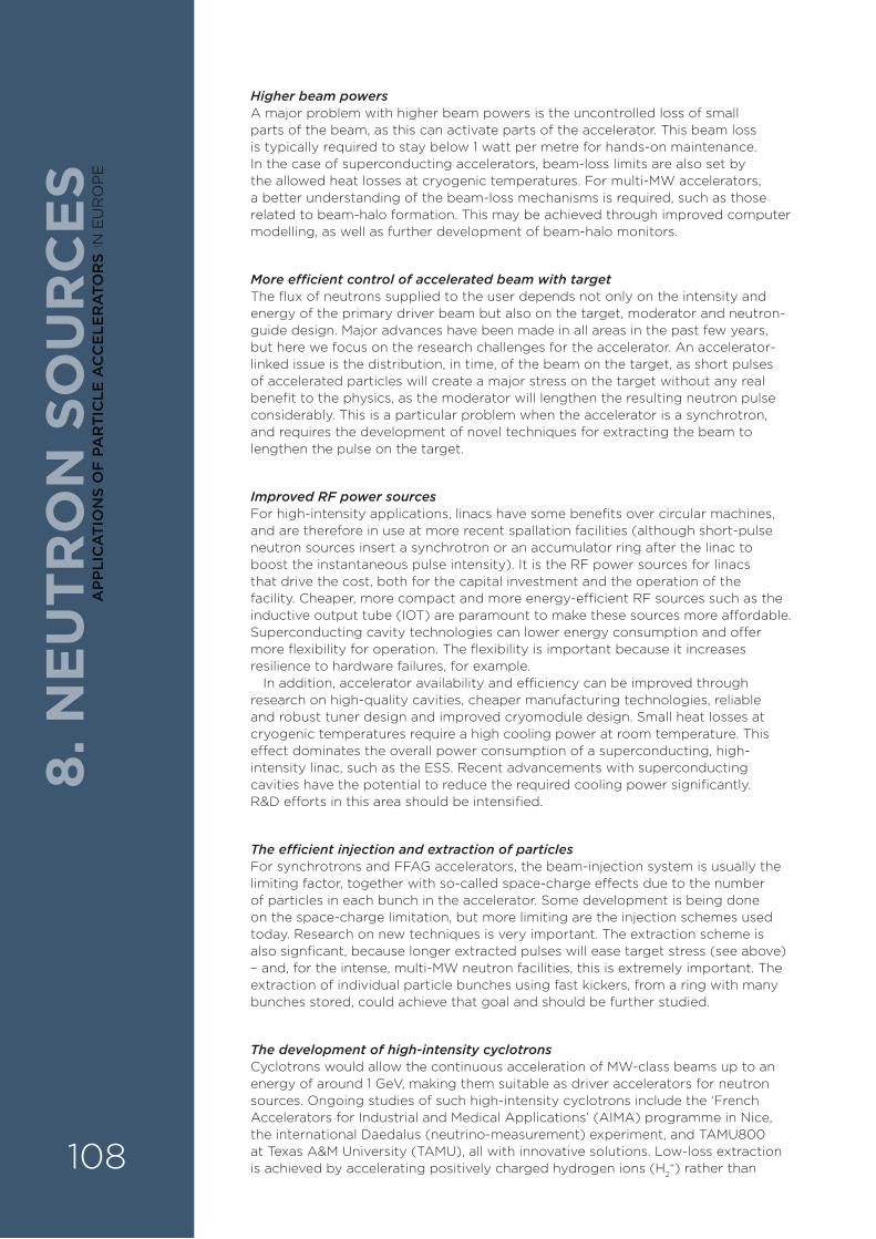
Higher beam powersA major problem with higher beam powers is the uncontrolled loss of small parts of the beam, as this can activate parts of the accelerator. This beam loss is typically required to stay below 1 watt per metre for hands-on maintenance. In the case of superconducting accelerators, beam-loss limits are also set by the allowed heat losses at cryogenic temperatures. For multi-MW accelerators, a better understanding of the beam-loss mechanisms is required, such as those related to beam-halo formation. This may be achieved through improved computer modelling, as well as further development of beam-halo monitors.
More e�cient control of accelerated beam with targetThe flux of neutrons supplied to the user depends not only on the intensity and energy of the primary driver beam but also on the target, moderator and neutron-guide design. Major advances have been made in all areas in the past few years, but here we focus on the research challenges for the accelerator. An accelerator-linked issue is the distribution, in time, of the beam on the target, as short pulses of accelerated particles will create a major stress on the target without any real benefit to the physics, as the moderator will lengthen the resulting neutron pulse considerably. This is a particular problem when the accelerator is a synchrotron, and requires the development of novel techniques for extracting the beam to lengthen the pulse on the target.
Improved RF power sourcesFor high-intensity applications, linacs have some benefits over circular machines, and are therefore in use at more recent spallation facilities (although short-pulse neutron sources insert a synchrotron or an accumulator ring after the linac to boost the instantaneous pulse intensity). It is the RF power sources for linacs that drive the cost, both for the capital investment and the operation of the facility. Cheaper, more compact and more energy-e§cient RF sources such as the inductive output tube (IOT) are paramount to make these sources more a¥ordable. Superconducting cavity technologies can lower energy consumption and o¥er more flexibility for operation. The flexibility is important because it increases resilience to hardware failures, for example.
In addition, accelerator availability and e§ciency can be improved through research on high-quality cavities, cheaper manufacturing technologies, reliable and robust tuner design and improved cryomodule design. Small heat losses at cryogenic temperatures require a high cooling power at room temperature. This e¥ect dominates the overall power consumption of a superconducting, high-intensity linac, such as the ESS. Recent advancements with superconducting cavities have the potential to reduce the required cooling power significantly. R&D e¥orts in this area should be intensified.
The e�cient injection and extraction of particlesFor synchrotrons and FFAG accelerators, the beam-injection system is usually the limiting factor, together with so-called space-charge e¥ects due to the number of particles in each bunch in the accelerator. Some development is being done on the space-charge limitation, but more limiting are the injection schemes used today. Research on new techniques is very important. The extraction scheme is also signficant, because longer extracted pulses will ease target stress (see above) – and, for the intense, multi-MW neutron facilities, this is extremely important. The extraction of individual particle bunches using fast kickers, from a ring with many bunches stored, could achieve that goal and should be further studied.
The development of high-intensity cyclotronsCyclotrons would allow the continuous acceleration of MW-class beams up to an energy of around 1 GeV, making them suitable as driver accelerators for neutron sources. Ongoing studies of such high-intensity cyclotrons include the ‘French Accelerators for Industrial and Medical Applications’ (AIMA) programme in Nice, the international Daedalus (neutrino-measurement) experiment, and TAMU800 at Texas A&M University (TAMU), all with innovative solutions. Low-loss extraction is achieved by accelerating positively charged hydrogen ions (H2
+) rather than
8. N
EU
TRO
N S
OU
RC
ES
108
AP
PLI
CA
TIO
NS
OF
PA
RT
ICLE
AC
CE
LER
ATO
RS
IN E
UR
OP
E

8. NE
UTR
ON
SOU
RC
ES
protons, and using the change in charge – resulting from stripping the remaining electron from the ion – for extraction (as is used in the Daedalus proposal, www.aima-developpement.fr/-highenergy; www2.lns.mit.edu/~conrad/daedalus.html).
Higher-energy CNSsFor higher-energy CNSs, a new generation of accelerating systems is needed. In addition, CNSs need to be inexpensive to manufacture, install and run (with low-energy consumption), and easy to operate. The major issues for beam physics arise at the early stage of acceleration where spatial charge confinement is challenging, and R&D is needed to understand this phenomenon better. To be able to address the needs of a wide user community, the accelerators should have a variable energy, so a combination of an RFQ with a small linear accelerator is recommended.
8.6. OTHER CHALLENGES Further technical challengesThere are also challenges for accelerator-driven neutron sources linked to the target, moderator, chopper, neutron guides, sample environment and detectors, and particularly the integration of all these aspects into facilities optimised for scientific impact. With the trend towards smaller samples , the brightness of the neutron flux becomes increasingly important. Neutron guides with focusing properties and low losses can contribute e¥ectively to the optimisation of the neutron flux at the site of the sample. Furthermore, the new generation of high-current accelerators for CNSs also require a new generation of much more e§cient target cooling systems, as the nuclear reactions used for CNSs are more than an order of magnitude less e§cient than in spallation sources, and thus a large amount of heat must be dissipated.
More investment in accelerator R&DTraditionally, accelerator R&D has been done mainly at nuclear and particle-physics laboratories. In the future, the neutron facilities must take on a much larger share of this and invest significantly in accelerator R&D.
Urgency in retaining skillsThe rapid closure of research reactors is quickly reducing research opportunities, which also reduces the number of active researchers. It is very important that new, small and large, accelerator-based neutron facilities come on-line as quickly as possible to stop this decay. The challenge for neutron sources here is to deliver on availability. Delivering on intensity is an additional challenge.
Impact on environmentThe energy e§ciency of the RF sources and cryogenics has already been discussed. It is worth adding that the overall energy use and environmental impact of the facility is also of very high importance. The requirements for facilities to reach a high degree of sustainability for all environmental impact issues are likely to be strengthened.
Organisation and financeFinally, the organisational and financial aspects of existing and future European facilities is a major challenge, and needs all possible support from relevant European political bodies. The in-kind model for the financing of new projects and possible upgrades is still under development. The present in-kind models are largely based on particle-physics experiments, where the link between users and builders is much stronger than for neutron sources. Issues that need to be addressed continuously in future projects are the transfer of risk, contingency management and the need for common cash funds for larger procurements, which are of little interest for in-kind partners.
109
AP
PLIC
AT
ION
S OF
PAR
TIC
LE A
CC
ELE
RA
TOR
S IN E
UR
OP
E
8.7. PRIORITY AREAS FOR R&DIn terms of the R&D mentioned above, priority should be given to topics that will improve the availability and energy e§ciency of existing and future facilities.
› More e°cient RF sources Specifically, the continued advance of more e§cient RF sources, and the development of superconducting-RF accelerator technologies for greater e§ciency and better reliability, is important.
› Injection and extraction schemes The injection and extraction schemes for circular accelerators should be given high priority.
› Alternative accelerator types The investigation of alternative accelerator types, such as FFAGs, which may present some advantages in e§ciency and availability if they can be demonstrated to work at high intensity.
› Compact CNSs with compact RFQs Since the future of the CNSs could be with small, compact RFQs, the priorities are the same as discussed above for this device. The existing RFQs are not yet competitive regarding investment and operation costs for commercial proton accelerators that work at low currents and low energies. There is a need to improve both the performance of electrostatic accelerators, and reduce the costs and power consumption of RFQs. Even though in Europe, CNSs based on high-power RFQs are quite close to becoming operational, none of them is there yet, and thus it is of high priority to get them operational very soon .
8.8. IMPACT ON INDUSTRY AND EDUCATIONNeutron research has many industrial applications, as mentioned earlier, for example, stress and fatigue studies, quality studies for manufacturing processes, and structural and dynamical studies of pharmaceutical products. CNSs are easy to operate, versatile and are relatively inexpensive to build and operate. This could make them available at many locations in Europe, which would greatly benefit industrial users, and help maintain a European industrial neutron-user community. Furthermore, simple and easy access to CNSs is important for R&D on the larger, high-flux neutron facilities, and for the training of students and new neutron users.
The high-flux neutron sources such as ISIS, the ILL and SINQ all have industrial users, both those who buy time at the facilities for studies where the result is proprietorial, and users who sponsor open research of general interest to industry .
8. N
EU
TRO
N S
OU
RC
ES
110
AP
PLI
CA
TIO
NS
OF
PA
RT
ICLE
AC
CE
LER
ATO
RS
IN E
UR
OP
E

8. NE
UTR
ON
SOU
RC
ES
8.9. KEY RECOMMENDATIONS FOR APPLICATIONS OF PARTICLE ACCELERATORS TO NEUTRON SOURCES
Political processes:A European roadmap is needed for the construction of new spallation sources and compact neutron sources, as well as the upgrade or replacement of existing sources. Furthermore, the neutron facilities must in the future invest in accelerator R&D and cannot depend on particle and nuclear physics to carry most of that cost.
High priority technical R&D is needed on:
› energy-eªcient RF sources;
› high-power RFQs;
› new low-loss injection schemes and ‘longer-pulse’ extraction schemes for synchrotrons;
› high-quality superconducting RF cavities;
› cheaper, more eªcient and more reliable superconducting and normal-conducting accelerating structures and accelerator systems.
111
AP
PLIC
AT
ION
S OF
PAR
TIC
LE A
CC
ELE
RA
TOR
S IN E
UR
OP
E
ADVANCES IN THE DEVELOPMENT AND APPLICATIONS OF PARTICLE ACCELERATORS HAVE INVOLVED A SIGNIFICANT R&D EFFORT OVER THE PAST 50 YEARS, AND HAVE HUGELY BENEFITED SOCIETY. IN ORDER TO CONTINUE THE PROGRESS MADE, IT IS ESSENTIAL TO ENCOURAGE R&D ACROSS THE WIDE RANGE OF DISCIPLINES THAT ARE ASSOCIATED WITH ACCELERATOR PHYSICS. MORE SPECIFICALLY, THE FOLLOWING RECOMMENDATIONS ARE MADE.
› COMPACT ACCELERATORS More-compact accelerator technology is a key factor in all applications. In this sense, the development, in the medium term, of superconducting components is crucial. In the longer term, laser and terahertz acceleration techniques could potentially o�er a dramatic reduction in size, although significant development is still needed to establish if this reduction can be achieved in a suitable environment.
› IMPROVED DESIGNS AND COST-EFFECTIVENESS Simpler and lower-cost designs and concepts, with higher e�ciency, reliability, robustness, and reduced costs of operation are needed in many accelerator applications, more specifically in health, industry and security; even the ready mobility of accelerator equipment is a growing need for some applications.
› IMPROVED ACADEMIA–INDUSTRY INTERACTIONS The development of accelerators for ‘big science’ drives the majority of advances in accelerator R&D worldwide. Manufacturers of accelerators for industrial and other uses are often not well connected to these e�orts. Programmes are required to better connect commercial accelerator groups, research facilities, universities and health centres.
9. S
UM
MA
RY
9. A SUMMARY OF KEY RECOMMENDATIONS FOR APPLICATIONS OF PARTICLE ACCELERATORS
112
AP
PLI
CA
TIO
NS
OF
PA
RT
ICLE
AC
CE
LER
ATO
RS
IN E
UR
OP
E

› IMPROVED STUDENT TRAINING AND KNOWLEDGE-TRANSFER The basic education and training of students in relevant fields are essential to increase the flow of a suitably trained workforce into industries manufacturing and applying accelerator technology; good knowledge-transfer into industry is also essential.
› IMPROVED PUBLIC UNDERSTANDING OF ACCELERATORS AND THEIR SCIENCEInvestment in the better public understanding of the science and applications of accelerators is needed, as well as better-informed perceptions of any risks.
› IMPROVED R&D COLLABORATION WITHIN THE EU A stronger coordination of R&D e�orts and collaborations at the EU level would be highly beneficial.
› FURTHER DEVELOPMENT OF COMBINED IRRADIATION AND IMAGING The merging of irradiation techniques and online-imaging is a major step, especially in the health and security sectors, where rapid and accurate detection (and treatment in the case of health) are desirable.
9. SUM
MA
RY
113
AP
PLIC
AT
ION
S OF
PAR
TIC
LE A
CC
ELE
RA
TOR
S IN E
UR
OP
E

NO
TES
114
AP
PLI
CA
TIO
NS
OF
PA
RT
ICLE
AC
CE
LER
ATO
RS
IN E
UR
OP
E

NO
TES
115
AP
PLIC
AT
ION
S OF
PAR
TIC
LE A
CC
ELE
RA
TOR
S IN E
UR
OP
E

CONTACTMaurizio Vretenar
email: [email protected]
MANAGING EDITORS Angeles Faus-Golfe
(IFIC Valencia – LAL Orsay), APAE coordinator
Rob Edgecock (U. Huddersfield – STFC)
June 2017
EuCARD-2 is co-funded by the partners and the
European Commission under Capacities 7 Framework
Programme, Grant Agreement 312453
EDITOR: Nina Hall
DESIGN: h2o-creative.com